EP2485832B1 - Process for producing a chlorinated and/or fluorinated propene in an isothermal multitube reactors and - Google Patents
Process for producing a chlorinated and/or fluorinated propene in an isothermal multitube reactors and Download PDFInfo
- Publication number
- EP2485832B1 EP2485832B1 EP10765730.6A EP10765730A EP2485832B1 EP 2485832 B1 EP2485832 B1 EP 2485832B1 EP 10765730 A EP10765730 A EP 10765730A EP 2485832 B1 EP2485832 B1 EP 2485832B1
- Authority
- EP
- European Patent Office
- Prior art keywords
- reactor
- reaction
- temperature
- chlorinated
- fluorinated
- Prior art date
- Legal status (The legal status is an assumption and is not a legal conclusion. Google has not performed a legal analysis and makes no representation as to the accuracy of the status listed.)
- Not-in-force
Links
- 238000000034 method Methods 0.000 title claims description 60
- 230000008569 process Effects 0.000 title claims description 52
- QQONPFPTGQHPMA-UHFFFAOYSA-N Propene Chemical class CC=C QQONPFPTGQHPMA-UHFFFAOYSA-N 0.000 title claims description 29
- 238000006243 chemical reaction Methods 0.000 claims description 163
- 239000006227 byproduct Substances 0.000 claims description 45
- 238000013461 design Methods 0.000 claims description 33
- NEHMKBQYUWJMIP-UHFFFAOYSA-N chloromethane Chemical class ClC NEHMKBQYUWJMIP-UHFFFAOYSA-N 0.000 claims description 30
- 238000004519 manufacturing process Methods 0.000 claims description 24
- 239000000047 product Substances 0.000 claims description 24
- 230000015572 biosynthetic process Effects 0.000 claims description 21
- UMGQVBVEWTXECF-UHFFFAOYSA-N 1,1,2,3-tetrachloroprop-1-ene Chemical compound ClCC(Cl)=C(Cl)Cl UMGQVBVEWTXECF-UHFFFAOYSA-N 0.000 claims description 18
- CYTYCFOTNPOANT-UHFFFAOYSA-N Perchloroethylene Chemical group ClC(Cl)=C(Cl)Cl CYTYCFOTNPOANT-UHFFFAOYSA-N 0.000 claims description 17
- 229940050176 methyl chloride Drugs 0.000 claims description 17
- 150000001336 alkenes Chemical class 0.000 claims description 15
- 238000012546 transfer Methods 0.000 claims description 15
- FXRLMCRCYDHQFW-UHFFFAOYSA-N 2,3,3,3-tetrafluoropropene Chemical compound FC(=C)C(F)(F)F FXRLMCRCYDHQFW-UHFFFAOYSA-N 0.000 claims description 13
- 238000010791 quenching Methods 0.000 claims description 13
- 239000000376 reactant Substances 0.000 claims description 13
- 239000012035 limiting reagent Substances 0.000 claims description 12
- CDOOAUSHHFGWSA-OWOJBTEDSA-N (e)-1,3,3,3-tetrafluoroprop-1-ene Chemical compound F\C=C\C(F)(F)F CDOOAUSHHFGWSA-OWOJBTEDSA-N 0.000 claims description 10
- 150000003254 radicals Chemical class 0.000 claims description 10
- 239000003054 catalyst Substances 0.000 claims description 9
- 238000002156 mixing Methods 0.000 claims description 9
- 239000007788 liquid Substances 0.000 claims description 7
- 150000001335 aliphatic alkanes Chemical class 0.000 claims description 6
- NBVXSUQYWXRMNV-UHFFFAOYSA-N fluoromethane Chemical class FC NBVXSUQYWXRMNV-UHFFFAOYSA-N 0.000 claims description 6
- 230000009467 reduction Effects 0.000 claims description 6
- 239000011248 coating agent Substances 0.000 claims description 5
- 238000000576 coating method Methods 0.000 claims description 5
- 239000000126 substance Substances 0.000 claims description 5
- ZRNSSRODJSSVEJ-UHFFFAOYSA-N 2-methylpentacosane Chemical compound CCCCCCCCCCCCCCCCCCCCCCCC(C)C ZRNSSRODJSSVEJ-UHFFFAOYSA-N 0.000 claims description 4
- 230000007246 mechanism Effects 0.000 claims description 4
- 238000002203 pretreatment Methods 0.000 claims description 4
- 230000000171 quenching effect Effects 0.000 claims description 4
- PGJHURKAWUJHLJ-UHFFFAOYSA-N 1,1,2,3-tetrafluoroprop-1-ene Chemical compound FCC(F)=C(F)F PGJHURKAWUJHLJ-UHFFFAOYSA-N 0.000 claims description 2
- ZYVSNYBYAYMMQV-UHFFFAOYSA-N 2-chloro-3-fluoroprop-1-ene Chemical compound FCC(Cl)=C ZYVSNYBYAYMMQV-UHFFFAOYSA-N 0.000 claims description 2
- XWCDCDSDNJVCLO-UHFFFAOYSA-N Chlorofluoromethane Chemical class FCCl XWCDCDSDNJVCLO-UHFFFAOYSA-N 0.000 claims description 2
- VNWKTOKETHGBQD-UHFFFAOYSA-N methane Chemical class C VNWKTOKETHGBQD-UHFFFAOYSA-N 0.000 claims description 2
- 239000000460 chlorine Substances 0.000 description 39
- 239000013529 heat transfer fluid Substances 0.000 description 30
- 239000012530 fluid Substances 0.000 description 17
- 239000012071 phase Substances 0.000 description 9
- 150000003839 salts Chemical class 0.000 description 8
- OKTJSMMVPCPJKN-UHFFFAOYSA-N Carbon Chemical compound [C] OKTJSMMVPCPJKN-UHFFFAOYSA-N 0.000 description 7
- 239000007789 gas Substances 0.000 description 7
- 239000000463 material Substances 0.000 description 6
- 230000008901 benefit Effects 0.000 description 5
- 238000000354 decomposition reaction Methods 0.000 description 5
- 238000010574 gas phase reaction Methods 0.000 description 5
- XLYOFNOQVPJJNP-UHFFFAOYSA-N water Substances O XLYOFNOQVPJJNP-UHFFFAOYSA-N 0.000 description 5
- MHCVCKDNQYMGEX-UHFFFAOYSA-N 1,1'-biphenyl;phenoxybenzene Chemical compound C1=CC=CC=C1C1=CC=CC=C1.C=1C=CC=CC=1OC1=CC=CC=C1 MHCVCKDNQYMGEX-UHFFFAOYSA-N 0.000 description 4
- 230000008859 change Effects 0.000 description 4
- 230000000052 comparative effect Effects 0.000 description 4
- 229910002804 graphite Inorganic materials 0.000 description 4
- 239000010439 graphite Substances 0.000 description 4
- PDEDQSAFHNADLV-UHFFFAOYSA-M potassium;disodium;dinitrate;nitrite Chemical compound [Na+].[Na+].[K+].[O-]N=O.[O-][N+]([O-])=O.[O-][N+]([O-])=O PDEDQSAFHNADLV-UHFFFAOYSA-M 0.000 description 4
- 239000011541 reaction mixture Substances 0.000 description 4
- VWDWKYIASSYTQR-UHFFFAOYSA-N sodium nitrate Chemical compound [Na+].[O-][N+]([O-])=O VWDWKYIASSYTQR-UHFFFAOYSA-N 0.000 description 4
- 229910052799 carbon Inorganic materials 0.000 description 3
- 229910052801 chlorine Inorganic materials 0.000 description 3
- 150000001875 compounds Chemical class 0.000 description 3
- -1 salt carbonates Chemical class 0.000 description 3
- 239000007921 spray Substances 0.000 description 3
- 230000003746 surface roughness Effects 0.000 description 3
- ZAMOUSCENKQFHK-UHFFFAOYSA-N Chlorine atom Chemical compound [Cl] ZAMOUSCENKQFHK-UHFFFAOYSA-N 0.000 description 2
- KRHYYFGTRYWZRS-UHFFFAOYSA-N Fluorane Chemical compound F KRHYYFGTRYWZRS-UHFFFAOYSA-N 0.000 description 2
- GRYLNZFGIOXLOG-UHFFFAOYSA-N Nitric acid Chemical compound O[N+]([O-])=O GRYLNZFGIOXLOG-UHFFFAOYSA-N 0.000 description 2
- VYPSYNLAJGMNEJ-UHFFFAOYSA-N Silicium dioxide Chemical compound O=[Si]=O VYPSYNLAJGMNEJ-UHFFFAOYSA-N 0.000 description 2
- ZCCIPPOKBCJFDN-UHFFFAOYSA-N calcium nitrate Chemical compound [Ca+2].[O-][N+]([O-])=O.[O-][N+]([O-])=O ZCCIPPOKBCJFDN-UHFFFAOYSA-N 0.000 description 2
- 238000003889 chemical engineering Methods 0.000 description 2
- 239000007795 chemical reaction product Substances 0.000 description 2
- 238000004939 coking Methods 0.000 description 2
- 238000004891 communication Methods 0.000 description 2
- 238000010924 continuous production Methods 0.000 description 2
- 238000001816 cooling Methods 0.000 description 2
- 235000012489 doughnuts Nutrition 0.000 description 2
- 238000011143 downstream manufacturing Methods 0.000 description 2
- 238000005658 halogenation reaction Methods 0.000 description 2
- 238000010438 heat treatment Methods 0.000 description 2
- 239000003999 initiator Substances 0.000 description 2
- 239000007791 liquid phase Substances 0.000 description 2
- 230000004048 modification Effects 0.000 description 2
- 238000012986 modification Methods 0.000 description 2
- FGIUAXJPYTZDNR-UHFFFAOYSA-N potassium nitrate Chemical compound [K+].[O-][N+]([O-])=O FGIUAXJPYTZDNR-UHFFFAOYSA-N 0.000 description 2
- 125000004805 propylene group Chemical group [H]C([H])([H])C([H])([*:1])C([H])([H])[*:2] 0.000 description 2
- 238000007348 radical reaction Methods 0.000 description 2
- LPXPTNMVRIOKMN-UHFFFAOYSA-M sodium nitrite Chemical compound [Na+].[O-]N=O LPXPTNMVRIOKMN-UHFFFAOYSA-M 0.000 description 2
- VZGDMQKNWNREIO-UHFFFAOYSA-N tetrachloromethane Chemical compound ClC(Cl)(Cl)Cl VZGDMQKNWNREIO-UHFFFAOYSA-N 0.000 description 2
- ZDCWZRQSHBQRGN-UHFFFAOYSA-N 1,1,1,2,3-pentafluoropropane Chemical compound FCC(F)C(F)(F)F ZDCWZRQSHBQRGN-UHFFFAOYSA-N 0.000 description 1
- FBSPLEKACMFIFU-UHFFFAOYSA-N 1,1,2,3-tetrachlorobut-1-ene Chemical class CC(Cl)C(Cl)=C(Cl)Cl FBSPLEKACMFIFU-UHFFFAOYSA-N 0.000 description 1
- USGZHDAFCVBESP-UHFFFAOYSA-N 1,1,2-trichloro-3-fluoroprop-1-ene Chemical group FCC(Cl)=C(Cl)Cl USGZHDAFCVBESP-UHFFFAOYSA-N 0.000 description 1
- XPIGFCKQOOBTLK-UHFFFAOYSA-N 1,1,3,3-tetrachloroprop-1-ene Chemical compound ClC(Cl)C=C(Cl)Cl XPIGFCKQOOBTLK-UHFFFAOYSA-N 0.000 description 1
- FPBWSPZHCJXUBL-UHFFFAOYSA-N 1-chloro-1-fluoroethene Chemical class FC(Cl)=C FPBWSPZHCJXUBL-UHFFFAOYSA-N 0.000 description 1
- SMCNZLDHTZESTK-UHFFFAOYSA-N 2-chloro-1,1,1,2-tetrafluoropropane Chemical compound CC(F)(Cl)C(F)(F)F SMCNZLDHTZESTK-UHFFFAOYSA-N 0.000 description 1
- OQISUJXQFPPARX-UHFFFAOYSA-N 2-chloro-3,3,3-trifluoroprop-1-ene Chemical compound FC(F)(F)C(Cl)=C OQISUJXQFPPARX-UHFFFAOYSA-N 0.000 description 1
- PXRKCOCTEMYUEG-UHFFFAOYSA-N 5-aminoisoindole-1,3-dione Chemical compound NC1=CC=C2C(=O)NC(=O)C2=C1 PXRKCOCTEMYUEG-UHFFFAOYSA-N 0.000 description 1
- VYZAMTAEIAYCRO-UHFFFAOYSA-N Chromium Chemical compound [Cr] VYZAMTAEIAYCRO-UHFFFAOYSA-N 0.000 description 1
- DGAQECJNVWCQMB-PUAWFVPOSA-M Ilexoside XXIX Chemical compound C[C@@H]1CC[C@@]2(CC[C@@]3(C(=CC[C@H]4[C@]3(CC[C@@H]5[C@@]4(CC[C@@H](C5(C)C)OS(=O)(=O)[O-])C)C)[C@@H]2[C@]1(C)O)C)C(=O)O[C@H]6[C@@H]([C@H]([C@@H]([C@H](O6)CO)O)O)O.[Na+] DGAQECJNVWCQMB-PUAWFVPOSA-M 0.000 description 1
- 229910002651 NO3 Inorganic materials 0.000 description 1
- NHNBFGGVMKEFGY-UHFFFAOYSA-N Nitrate Chemical compound [O-][N+]([O-])=O NHNBFGGVMKEFGY-UHFFFAOYSA-N 0.000 description 1
- IOVCWXUNBOPUCH-UHFFFAOYSA-M Nitrite anion Chemical compound [O-]N=O IOVCWXUNBOPUCH-UHFFFAOYSA-M 0.000 description 1
- 101100409194 Rattus norvegicus Ppargc1b gene Proteins 0.000 description 1
- 239000002253 acid Substances 0.000 description 1
- 238000013459 approach Methods 0.000 description 1
- 238000005422 blasting Methods 0.000 description 1
- 230000015556 catabolic process Effects 0.000 description 1
- 230000003197 catalytic effect Effects 0.000 description 1
- 238000006555 catalytic reaction Methods 0.000 description 1
- 239000000919 ceramic Substances 0.000 description 1
- 229910052804 chromium Inorganic materials 0.000 description 1
- 239000011651 chromium Substances 0.000 description 1
- 238000004140 cleaning Methods 0.000 description 1
- GSOLWAFGMNOBSY-UHFFFAOYSA-N cobalt Chemical compound [Co][Co][Co][Co][Co][Co][Co][Co] GSOLWAFGMNOBSY-UHFFFAOYSA-N 0.000 description 1
- 229910017052 cobalt Inorganic materials 0.000 description 1
- 239000010941 cobalt Substances 0.000 description 1
- 239000000356 contaminant Substances 0.000 description 1
- 239000002826 coolant Substances 0.000 description 1
- 238000005260 corrosion Methods 0.000 description 1
- 230000007797 corrosion Effects 0.000 description 1
- 238000006731 degradation reaction Methods 0.000 description 1
- 230000001627 detrimental effect Effects 0.000 description 1
- 239000003085 diluting agent Substances 0.000 description 1
- 238000004090 dissolution Methods 0.000 description 1
- 238000009826 distribution Methods 0.000 description 1
- 230000000694 effects Effects 0.000 description 1
- 238000001914 filtration Methods 0.000 description 1
- 238000003682 fluorination reaction Methods 0.000 description 1
- 238000000227 grinding Methods 0.000 description 1
- 230000026030 halogenation Effects 0.000 description 1
- 229910000856 hastalloy Inorganic materials 0.000 description 1
- 239000012535 impurity Substances 0.000 description 1
- 229910001055 inconels 600 Inorganic materials 0.000 description 1
- 238000012423 maintenance Methods 0.000 description 1
- 238000005259 measurement Methods 0.000 description 1
- 238000009996 mechanical pre-treatment Methods 0.000 description 1
- 239000000203 mixture Substances 0.000 description 1
- 239000003607 modifier Substances 0.000 description 1
- 239000002103 nanocoating Substances 0.000 description 1
- 239000002086 nanomaterial Substances 0.000 description 1
- 229910017604 nitric acid Inorganic materials 0.000 description 1
- 231100000252 nontoxic Toxicity 0.000 description 1
- 230000003000 nontoxic effect Effects 0.000 description 1
- 239000003921 oil Substances 0.000 description 1
- 238000005457 optimization Methods 0.000 description 1
- 238000002161 passivation Methods 0.000 description 1
- 238000005554 pickling Methods 0.000 description 1
- 238000012545 processing Methods 0.000 description 1
- 230000001737 promoting effect Effects 0.000 description 1
- 230000009257 reactivity Effects 0.000 description 1
- 238000000926 separation method Methods 0.000 description 1
- 238000007086 side reaction Methods 0.000 description 1
- 239000000377 silicon dioxide Substances 0.000 description 1
- 239000011734 sodium Substances 0.000 description 1
- 229910052708 sodium Inorganic materials 0.000 description 1
- 238000006467 substitution reaction Methods 0.000 description 1
- 238000005979 thermal decomposition reaction Methods 0.000 description 1
- 230000008542 thermal sensitivity Effects 0.000 description 1
- 238000011282 treatment Methods 0.000 description 1
Images
Classifications
-
- B—PERFORMING OPERATIONS; TRANSPORTING
- B01—PHYSICAL OR CHEMICAL PROCESSES OR APPARATUS IN GENERAL
- B01J—CHEMICAL OR PHYSICAL PROCESSES, e.g. CATALYSIS OR COLLOID CHEMISTRY; THEIR RELEVANT APPARATUS
- B01J19/00—Chemical, physical or physico-chemical processes in general; Their relevant apparatus
- B01J19/24—Stationary reactors without moving elements inside
- B01J19/2415—Tubular reactors
- B01J19/2425—Tubular reactors in parallel
-
- B—PERFORMING OPERATIONS; TRANSPORTING
- B01—PHYSICAL OR CHEMICAL PROCESSES OR APPARATUS IN GENERAL
- B01J—CHEMICAL OR PHYSICAL PROCESSES, e.g. CATALYSIS OR COLLOID CHEMISTRY; THEIR RELEVANT APPARATUS
- B01J19/00—Chemical, physical or physico-chemical processes in general; Their relevant apparatus
-
- B—PERFORMING OPERATIONS; TRANSPORTING
- B01—PHYSICAL OR CHEMICAL PROCESSES OR APPARATUS IN GENERAL
- B01J—CHEMICAL OR PHYSICAL PROCESSES, e.g. CATALYSIS OR COLLOID CHEMISTRY; THEIR RELEVANT APPARATUS
- B01J19/00—Chemical, physical or physico-chemical processes in general; Their relevant apparatus
- B01J19/0006—Controlling or regulating processes
- B01J19/002—Avoiding undesirable reactions or side-effects, e.g. avoiding explosions, or improving the yield by suppressing side-reactions
- B01J19/0026—Avoiding carbon deposits
-
- B—PERFORMING OPERATIONS; TRANSPORTING
- B01—PHYSICAL OR CHEMICAL PROCESSES OR APPARATUS IN GENERAL
- B01J—CHEMICAL OR PHYSICAL PROCESSES, e.g. CATALYSIS OR COLLOID CHEMISTRY; THEIR RELEVANT APPARATUS
- B01J19/00—Chemical, physical or physico-chemical processes in general; Their relevant apparatus
- B01J19/0053—Details of the reactor
- B01J19/006—Baffles
-
- B—PERFORMING OPERATIONS; TRANSPORTING
- B01—PHYSICAL OR CHEMICAL PROCESSES OR APPARATUS IN GENERAL
- B01J—CHEMICAL OR PHYSICAL PROCESSES, e.g. CATALYSIS OR COLLOID CHEMISTRY; THEIR RELEVANT APPARATUS
- B01J19/00—Chemical, physical or physico-chemical processes in general; Their relevant apparatus
- B01J19/24—Stationary reactors without moving elements inside
-
- B—PERFORMING OPERATIONS; TRANSPORTING
- B01—PHYSICAL OR CHEMICAL PROCESSES OR APPARATUS IN GENERAL
- B01J—CHEMICAL OR PHYSICAL PROCESSES, e.g. CATALYSIS OR COLLOID CHEMISTRY; THEIR RELEVANT APPARATUS
- B01J19/00—Chemical, physical or physico-chemical processes in general; Their relevant apparatus
- B01J19/24—Stationary reactors without moving elements inside
- B01J19/2405—Stationary reactors without moving elements inside provoking a turbulent flow of the reactants, such as in cyclones, or having a high Reynolds-number
-
- C—CHEMISTRY; METALLURGY
- C07—ORGANIC CHEMISTRY
- C07C—ACYCLIC OR CARBOCYCLIC COMPOUNDS
- C07C17/00—Preparation of halogenated hydrocarbons
- C07C17/093—Preparation of halogenated hydrocarbons by replacement by halogens
- C07C17/20—Preparation of halogenated hydrocarbons by replacement by halogens of halogen atoms by other halogen atoms
- C07C17/202—Preparation of halogenated hydrocarbons by replacement by halogens of halogen atoms by other halogen atoms two or more compounds being involved in the reaction
- C07C17/206—Preparation of halogenated hydrocarbons by replacement by halogens of halogen atoms by other halogen atoms two or more compounds being involved in the reaction the other compound being HX
-
- C—CHEMISTRY; METALLURGY
- C07—ORGANIC CHEMISTRY
- C07C—ACYCLIC OR CARBOCYCLIC COMPOUNDS
- C07C17/00—Preparation of halogenated hydrocarbons
- C07C17/26—Preparation of halogenated hydrocarbons by reactions involving an increase in the number of carbon atoms in the skeleton
- C07C17/263—Preparation of halogenated hydrocarbons by reactions involving an increase in the number of carbon atoms in the skeleton by condensation reactions
- C07C17/269—Preparation of halogenated hydrocarbons by reactions involving an increase in the number of carbon atoms in the skeleton by condensation reactions of only halogenated hydrocarbons
-
- C—CHEMISTRY; METALLURGY
- C07—ORGANIC CHEMISTRY
- C07C—ACYCLIC OR CARBOCYCLIC COMPOUNDS
- C07C21/00—Acyclic unsaturated compounds containing halogen atoms
- C07C21/02—Acyclic unsaturated compounds containing halogen atoms containing carbon-to-carbon double bonds
- C07C21/17—Acyclic unsaturated compounds containing halogen atoms containing carbon-to-carbon double bonds containing iodine
-
- C—CHEMISTRY; METALLURGY
- C07—ORGANIC CHEMISTRY
- C07C—ACYCLIC OR CARBOCYCLIC COMPOUNDS
- C07C21/00—Acyclic unsaturated compounds containing halogen atoms
- C07C21/02—Acyclic unsaturated compounds containing halogen atoms containing carbon-to-carbon double bonds
- C07C21/18—Acyclic unsaturated compounds containing halogen atoms containing carbon-to-carbon double bonds containing fluorine
-
- B—PERFORMING OPERATIONS; TRANSPORTING
- B01—PHYSICAL OR CHEMICAL PROCESSES OR APPARATUS IN GENERAL
- B01J—CHEMICAL OR PHYSICAL PROCESSES, e.g. CATALYSIS OR COLLOID CHEMISTRY; THEIR RELEVANT APPARATUS
- B01J2219/00—Chemical, physical or physico-chemical processes in general; Their relevant apparatus
- B01J2219/00049—Controlling or regulating processes
- B01J2219/00051—Controlling the temperature
- B01J2219/00054—Controlling or regulating the heat exchange system
- B01J2219/00056—Controlling or regulating the heat exchange system involving measured parameters
- B01J2219/00058—Temperature measurement
- B01J2219/00063—Temperature measurement of the reactants
-
- B—PERFORMING OPERATIONS; TRANSPORTING
- B01—PHYSICAL OR CHEMICAL PROCESSES OR APPARATUS IN GENERAL
- B01J—CHEMICAL OR PHYSICAL PROCESSES, e.g. CATALYSIS OR COLLOID CHEMISTRY; THEIR RELEVANT APPARATUS
- B01J2219/00—Chemical, physical or physico-chemical processes in general; Their relevant apparatus
- B01J2219/00049—Controlling or regulating processes
- B01J2219/00051—Controlling the temperature
- B01J2219/00074—Controlling the temperature by indirect heating or cooling employing heat exchange fluids
- B01J2219/00076—Controlling the temperature by indirect heating or cooling employing heat exchange fluids with heat exchange elements inside the reactor
- B01J2219/00081—Tubes
-
- B—PERFORMING OPERATIONS; TRANSPORTING
- B01—PHYSICAL OR CHEMICAL PROCESSES OR APPARATUS IN GENERAL
- B01J—CHEMICAL OR PHYSICAL PROCESSES, e.g. CATALYSIS OR COLLOID CHEMISTRY; THEIR RELEVANT APPARATUS
- B01J2219/00—Chemical, physical or physico-chemical processes in general; Their relevant apparatus
- B01J2219/00049—Controlling or regulating processes
- B01J2219/00051—Controlling the temperature
- B01J2219/00159—Controlling the temperature controlling multiple zones along the direction of flow, e.g. pre-heating and after-cooling
-
- B—PERFORMING OPERATIONS; TRANSPORTING
- B01—PHYSICAL OR CHEMICAL PROCESSES OR APPARATUS IN GENERAL
- B01J—CHEMICAL OR PHYSICAL PROCESSES, e.g. CATALYSIS OR COLLOID CHEMISTRY; THEIR RELEVANT APPARATUS
- B01J2219/00—Chemical, physical or physico-chemical processes in general; Their relevant apparatus
- B01J2219/00049—Controlling or regulating processes
- B01J2219/00162—Controlling or regulating processes controlling the pressure
-
- B—PERFORMING OPERATIONS; TRANSPORTING
- B01—PHYSICAL OR CHEMICAL PROCESSES OR APPARATUS IN GENERAL
- B01J—CHEMICAL OR PHYSICAL PROCESSES, e.g. CATALYSIS OR COLLOID CHEMISTRY; THEIR RELEVANT APPARATUS
- B01J2219/00—Chemical, physical or physico-chemical processes in general; Their relevant apparatus
- B01J2219/00049—Controlling or regulating processes
- B01J2219/00164—Controlling or regulating processes controlling the flow
- B01J2219/00166—Controlling or regulating processes controlling the flow controlling the residence time inside the reactor vessel
-
- B—PERFORMING OPERATIONS; TRANSPORTING
- B01—PHYSICAL OR CHEMICAL PROCESSES OR APPARATUS IN GENERAL
- B01J—CHEMICAL OR PHYSICAL PROCESSES, e.g. CATALYSIS OR COLLOID CHEMISTRY; THEIR RELEVANT APPARATUS
- B01J2219/00—Chemical, physical or physico-chemical processes in general; Their relevant apparatus
- B01J2219/00049—Controlling or regulating processes
- B01J2219/00245—Avoiding undesirable reactions or side-effects
- B01J2219/00247—Fouling of the reactor or the process equipment
-
- B—PERFORMING OPERATIONS; TRANSPORTING
- B01—PHYSICAL OR CHEMICAL PROCESSES OR APPARATUS IN GENERAL
- B01J—CHEMICAL OR PHYSICAL PROCESSES, e.g. CATALYSIS OR COLLOID CHEMISTRY; THEIR RELEVANT APPARATUS
- B01J2219/00—Chemical, physical or physico-chemical processes in general; Their relevant apparatus
- B01J2219/02—Apparatus characterised by their chemically-resistant properties
- B01J2219/0204—Apparatus characterised by their chemically-resistant properties comprising coatings on the surfaces in direct contact with the reactive components
- B01J2219/0227—Apparatus characterised by their chemically-resistant properties comprising coatings on the surfaces in direct contact with the reactive components of graphite
Definitions
- the present invention relates to a process for producing chlorinated and/or fluorinated propene by the reaction of chlorinated and/or fluorinated alkanes and chlorinated and/or fluorinated alkenes in a continuous, gas phase, free radical process using an isothermal multitube reactor.
- US 568902 , WO 2008/030441 A1 , US 6111150 and US4513154 disclose processes for producing chlorinated and/or fluorinated alkanes or alkenes.
- Multitube reactors are ubiquitous in the manufacture of commodity chemicals. These reactors, which may comprise a normally substantially vertical vessel further comprising a plurality of open ended reactor tubes, are typically used for catalyzed gas-phase reactions.
- the shell of a multitube reactor for such processes may typically have a diameter of several meters and include from as few as about 5000 up to as many as about 50000 reaction tubes. Each reactor tube may be as long as 5, 10 or even 15 meters.
- the upper ends of the reactor tubes may generally be affixed to an upper tube sheet and be in fluid communication with a fluid inlet head above the upper tube sheet.
- the lower ends of the reactor tubes may generally be affixed to a lower tube sheet and in fluid communication with an effluent collecting head below the lower tube sheet.
- the desired reactant gases are supplied to the fluid inlet chamber at the upper ends of the reactor tubes and passed therethrough. Effluents leaving the lower ends of the reactor tubes are collected in the effluent collecting head.
- the heat of reaction is removed by a heat transfer fluid which is passed across the outer surfaces of the reactor tubes.
- temperature control in multitube reactors can be challenging, Yet, precise temperature control may often be desirable, or even required, within many manufacturing processes.
- accurate temperature control can be critical in maintaining the desired reaction rate.
- Process inhomogeneities e.g., hot spots, if allowed to occur, can result in increased reaction rate and conversion, which for many reactions; can result in an undesirable decrease in selectivity.
- undesirable temperature fluctuations can detrimentally impact any thermally sensitive components or inputs utilized in the reaction.
- undesirably fluctuating temperatures can lead to reduced catalyst life, and degradation of thermally sensitive components, which, in turn, can result in fouling of the reactor tubes.
- the residence time of reaction components within the process must also be considered. That is, the detrimental impact of ineffective temperature control may be exacerbated if reaction components have a residence time at the suboptimal temperature that allows for an increase in conversion and/or reaction or decomposition of thermally sensitive components.
- Such a process for producing chlorinated and/or fluorinated propene by the reaction of chlorinated and/or fluorinated alkanes and chlorinated and/or fluorinated alkenes in a continuous, gas phase, free radical process using an isothermal multitube reactor is provided in claim 1. More specifically, the reactor described herein can provide not only more accurate temperature control via more effective heat transfer into and/or out of the reactor, but also, can provide appropriate residence times of reaction components so that desired conversions and/or selectivities can be seen.
- the reactor is thus particularly well suited for reactions comprising thermally sensitive components such as catalysts that may otherwise exhibit reduced lifetimes, or reaction components that undesirably react or decompose at temperatures within the processing specifications of the process desirably carried out within the reactor.
- a process for producing chlorinated and/or fluorinated propene in an isothermal multitube reactor comprising a plurality of reactor tubes situated within a shell.
- the process is a continuous, gas-phase, free radical process for the production of chlorinated and/or fluorinated propene and higher alkenes and utilizes a feed mixture temperature at least 20°C lower than the desired reaction temperature.
- the reactor may further comprise a design that minimizes the production of by-products at a desired conversion.
- a design that facilitates heat transfer to and/or from the reactor including i) a design that facilitates heat transfer to and/or from the reactor; ii) a design that facilitates reduced backmixing or recirculation upon exit from, the reactor, and/or reduced formation of by-products during any backmixing that may occur; iii) a design that optimizes the flow of the reaction components at the boundary between the reaction components and at least a portion of at least one reactor tube wall; and/or iv) a design that facilitates a reduction of the temperature of a reactor effluent to a temperature below which substantial formation of by-products does not occur. Combinations of one or more of these may be utilized, in which case the benefits provided by one may be further leveraged, perhaps even synergistically, by addition of the other(s).
- the present reactors are expected to provide time and cost savings to the continuous processes in which they are utilized, not only are processes utilizing the reactors provided, but the products produced thereby may be used to carry these advantages forward, i.e., to downstream processes, or to end-uses.
- processes for the use of a chlorinated and/or fluorinated propene and higher alkene which in some embodiments may be a chlorinated propene, produced in the present reactors to prepare a downstream product, which in some embodiments, may be 2,3,3,3-tetrafluoroprop-1-ene (HFO-1234yf) or 1,3,3,3-tetrafluoroprop-1-ene (HFO-1234ze).
- first”, “second”, and the like, as used herein do not denote any order, quantity, or importance, but rather are used to distinguish one element from another. Also, the terms “a” and “an” do not denote a limitation of quantity, but rather denote the presence of at least one of the referenced item, and the terms “front”, “back”, “bottom”, and/or “top”, unless otherwise noted, are merely used for convenience of description, and are not intended to limit the part being described limited to any one position or spatial orientation.
- ranges are inclusive and independently combinable (e.g., ranges of "up to about 25 wt.%, or, more specifically, about 5 wt.% to about 20 wt.%,” is inclusive of the endpoints and all intermediate values of the ranges of "about 5 wt.% to about 25 wt.%,” etc.).
- the modifier "about” used in connection with a quantity is inclusive of the stated value and has the meaning dictated by the context (e.g., includes the degree of error associated with measurement of the particular quantity).
- percent (%) conversion is meant to indicate change in molar or mass flow of reactant in a reactor in ratio to the incoming flow
- percent (%) selectivity means the change in molar flow rate of product in a reactor in ratio to the change of molar flow rate of a reactant
- the present invention provides a process using an isothermal multitube reactor in a continuous, gas-phase, free radical process for the production of chlorinated and/or fluorinated propene and higher alkenes.
- reaction spaces provided within the reactor can be of any geometry, as can the shell surrounding them. That is, the reaction spaces can be defined by plates, so that they are generally in the form of slits, or, the reaction spaces may be defined by square, triangular, or oval tubes.
- the reactor comprises a design that minimizes the production of by-products, including decomposition products of reaction components that may foul the reactor.
- the percent conversion of the reaction carried out within the reactor may be kept within a desired range, e.g., the percent conversion of the reaction desirably increases by less than about 5%, or less than about 2%, or preferably, increases by less than about 1%, so that a high percent selectivity, e.g., 70% or greater, may be seen.
- selectivity to the desired product can be as high as about 70%, or about 75%, or about 80%, or even about 85% or greater.
- the present reactor is particularly well suited for conducting reactions for which an increase in percent conversion may typically indicate increased production of reaction by-products, and thus, reduced percent selectivity.
- the reactors described herein may be utilized in any continuous gas-phase, free radical process, and in particular, are well suited for such reactions that are also homogeneous and exothermic.
- the reactors described herein are also particularly appropriately employed for reactions involving at least one limiting reactant having a desired conversion far from exhaustion of the same, e.g., mass or molar conversions of less than 80%, or less than 40%, or even less than 20% of the limiting reactant.
- the present reactors are also particularly well suited for such reactions particularly susceptible to the formation of by-products, and the effects thereof on reaction selectivity, or comprising thermally sensitive components, e.g., that may react, or degrade, to form undesirable by-products.
- Thermally sensitive components may include, for example, reactants, products, catalysts, and even by-products which may further react or thermally degrade to form other by-products. Reactions comprising combinations of thermally sensitive components may also find benefit from being carried out in the present reactors. Even at such low conversions of limiting reagent, and when used to conduct reactions susceptible to the formation of by-products, the present reactors can provide selectivity to the desired product of at least about 70%, or about 75%, or about 80%, or even about 85% or greater.
- the process according to the present invention is limited to reactions that produce chlorinated and/or fluorinated propene.
- Particular exemplary reactions include the reaction of methyl chloride with perchloroethylene to provide 1,1,2,3-tetrachloropropene, the reaction of methyl fluoride with perchloroethylene to provide 1,1,2-chloro-3-fluoro-propene and the reaction of methyl fluoride with triflurochloroethylene to provide 1,1,2,3-tetrafluoropropene.
- these references are intended only to be exemplary and are not to be construed as limiting to the reactors and concepts described herein.
- processes for the production of chlorinated or fluorinated propenes may typically result in the formation of larger quantities of reaction by-products than conventional halogenation processes. That is, In conventional free radical halogenation reactions, reactor promoted backmixing or recirculation such as that provided by jet stirred reactors, is typically considered to increase productivity of the reactor with little impact on byproduct formation [ Liu et al, Chemical Engineering Science 59 (2004) 5167-5176 ]. In addition, jet stirred reactors are typically operated at adiabatic conditions, where heat transfer to the surroundings is minimized.
- isothermal multitube reactors can be used in a process according to claim 1 if the inlet temperature is caused to be lower than the desired reaction temperature, or the temperature at which substantial amounts of by-products will form, by at least about 20°C, or by about 50°C, or by about 100°C.
- the temperature at the inlet/mixer of the reactor is not conducive to the formation of by-products, and yet, the mixing of the reactants that needs to occur in the inlet/mixer can occur so that the reaction tubes and reactor size can be of an economical size.
- an inlet temperature of less than about 370°C, or less than 325°C would be suitable to discourage or prevent formation of by-products, such as tetrachlorobutenes, graphite, and other carbonaceous deposits.
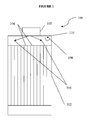
- FIG 1 a typical configuration of a multitube reactor 100 comprising inlet 102 is shown.
- the flow of the reactants may generally proceed toward the inlets of reactor tubes 104 as shown by arrows 106.
- This flow pattern may create areas of backmixing and/or recirculation indicated by arrows 108.
- the impact of any such backmixing or recirculation zone may be minimized by maintaining the temperature within region 110 at a lower temperature of 20°C, or preferably 50°C, or even more preferably 100°C than the temperature required for the reaction components present to react to form significant amounts of by-products.
- a temperature of less than about 370°C, or less than about 325°C would be sufficient for this purpose.
- the reactor may additionally comprise one or more other design features to further minimize the formation of by-products, or to reduce or eliminate the impact of any by-products that are formed.
- the reactors provided herein may comprise one or more i) a design that facilitates heat transfer to and/or from the reactor; ii) a design that facilitates reduced backmixing or recirculation upon exit from, the reactor, and/or reduced formation of by-products during any backmixing or recirculation that may occur; iii) a design that optimizes the flow of the reaction components at the boundary between the reaction components and at least a portion of at least one reactor tube wall; and/or iv) a design that facilitates a reduction of the temperature of a reactor effluent to a temperature below which substantial formation of by-products does not occur. Any number of the reactor designs described herein may be used in any combination.
- the reactor provided herein may comprise a design that facilitates heat transfer to, from and/or within the reactor so that the reactor may operate substantially isothermally within the reaction zone.
- the term "isothermally" as applied to the multitube reactors described herein means that, at steady state conditions, the temperature within the reaction zone remains substantially constant, i.e., will vary only by about 10°C, or only by about 5°C or even by only about 1°C, or even less, once the desired reaction temperature has been reached.
- Heat transfer fluids are typically used for this purpose and are introduced through an inlet in the shell into the space between the shell and the reactor tubes.
- Appropriate heat transfer fluids have high thermal capacity, low viscosity, are low-cost, non-toxic, and chemically inert, neither causing nor promoting corrosion of the cooling/heating system.
- the heat transfer fluid will assist in the isothermal operation of the reactor, and thus, the integrity of any thermally sensitive reaction component(s) therein.
- suitable heat transfer fluids include, but are not limited to, molten salts such as salt carbonates, sodium (nitrite/nitrate (NaNO 2 /NaNO 3 ) or HitecXL® (a ternary salt consisting of 48% Ca(NO 3 ) 2 , 7% NaNO 3 , and 45% KNO 3 , oils such as Syltherm®, Dowtherm®, or water.
- molten salts such as salt carbonates, sodium (nitrite/nitrate (NaNO 2 /NaNO 3 ) or HitecXL® (a ternary salt consisting of 48% Ca(NO 3 ) 2 , 7% NaNO 3 , and 45% KNO 3
- oils such as Syltherm®, Dowtherm®, or water.
- the shell may be provided with one or more blind baffles, effective to thermally isolate one section of the shell/reactor tubes from another section of the shell/reactor tubes, wherein each section may be provided with the same or different heat transfer fluid.
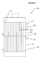
- a reactor is shown schematically in FIG 2 . More particularly, FIG. 2 shows multitube reactor 200, comprising a plurality of reactor tubes 202 within shell 204. Baffle 206 is provided that thermally isolates reactor section 208 from reactor section 210.
- Heat transfer fluid inlet 212 is provided to fluidly connected space 214 with a first heat transfer fluid source (not shown).
- Heat transfer fluid inlet 216 is also provided, and fluidly connects space 218 to a second heat transfer fluid source (not shown).
- the heat transfer fluids utilized in each section may be the same or different, although the temperatures thereof may desirably differ, e.g., to facilitate the use of different temperatures within reactor sections 208 and 210.
- Syltherm® or Hitec® molten salt may be used as a heat transfer fluid and may be provided through heat transfer fluid inlet 212 to space 214 at a temperature of from about 400°C to about 430°C, typically at a temperature of about 415°C to assist in raising the temperature within the reactor tubes to the desired reaction temperature.
- Syltherm® may also be used within space 218, and may be provided thereto through heat transfer fluid inlet 216 at a temperature of from about 370°C to about 420°C, typically at a temperature of about 395°C.
- the heat transfer fluid within space 218 will desirably remove heat generated by the exothermic reaction from the reaction zone, and assist maintaining the temperature therein. As such, enough reaction volume is provided to allow for sufficient residence time such that the desirable conversion percent can be achieved, while substantial byproduct formation is also minimized.
- the design facilitating heat transfer within the reactor may also comprise providing a co-current flow of the desired heat transfer fluid(s) within the shell and about the reactor tubes.
- the use of such a co-current flow would involve providing a heat transfer fluid having a temperature appropriate to assist in preheating the feed into the reactor and reaction zone to the desired temperature, while in the reaction zone, the heat transfer fluid would desirably have a temperature sufficient to assist in the reaction zone maintaining the desired temperature.
- the heat transfer fluid would desirable be provided at a temperature sufficient to raise the reactor tubes and the feed to the desired temperature, and, within the reaction zone, would assist in the removal of heat therefrom, i.e., the heat transfer fluid would be at a lower temperature than the reaction zone.
- the particular temperature at which the heat transfer fluid is supplied to the reactor tubes/reaction zone in this embodiment will depend upon the extent of the exothermic reaction being carried out for the production of particular chlorinated and/or fluorinated propylene or higher alkene considered here.
- the temperature of the heat transfer fluid may also depend upon the particular heat transfer fluid being utilized, and the desired temperature maintained.
- the heat transfer fluid may be caused to be at a temperature substantially equal to, or within about 50°C higher than, the desired reaction temperature upon entry into the reactor, and within about 10°C less than, the desired reaction temperature within a reaction zone of the reactor. That is, the heat transfer fluid may be at a temperature higher than the desired reaction upon entry into the reaction zone within the reactor and at a temperature lower than the desired reaction temperature at the end the reaction zone within the reactor since the reaction to be carried out is exothermic.
- a molten salt such as Dowtherm®
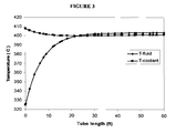
- a heat transfer fluid can be used as a heat transfer fluid, and in order to provide co-current flow, will desirably have a temperature of about 410°C upon entry in to the reactor tubes. This temperature will desirably increase at an appropriate rate, so that by the time the heat transfer fluid reaches the reaction zone, the reaction zone is at a temperature of about 390°C and the heat transfer fluid is at a temperature of about 405°C.
- FIG. 3 a graph showing the relationship between the temperature of the heat transfer fluid and temperature of the reaction components and/or reactor, versus the reactor tube length for this embodiment of the invention.
- the reactor may also be provided with one or more designs that facilitate reduced backmixing and/or recirculation and/or reduced formation of by-products during any backmixing and/or recirculation that may occur upon exit from, the reactor.
- One example of such a design involves the use of the reactor without a collector, or the redesign of any collector desirably utilized to minimize backmixing and/or recirculation zone. That is, many multitube reactors may be configured with a collector fluidly connected thereto reactor effluent is dispensed therefrom, as the case may be. Backmixing and/or recirculation may typically occur in such conventional collectors, or collectors arranged conventionally with respect to the reactor.
- the present reactors may be provided without a collector, so that the reactor effluent is passed from the reactor directly to a liquid quench zone.
- the diameter/shape of the reactor and a collector may be configured to be substantially the same, so that areas of backmixing are not created in dead space created by disparate geometries between the reactor and collector. Any such collector will also desirably be placed about the same longitudinal axis as the reactor.
- Increased residence time through conventional multitube reactors may also lead to the formation of undesirable by-products, and may generally occur due to the velocity gradient layer at the interface between an internal wall of a reactor tube and the reaction mixture flowing therethrough.
- the velocity of the reaction mixture in this layer is typically less than the velocity of the reaction mixture in the bulk velocity. Indeed, the velocity of the velocity gradient layer can approach zero at the reactor wall. Because of this lower velocity, reactants in this layer may experience longer residence time(s) during which unwanted side reactions may occur. Minimizing any such layer can assist in the optimization of the residence time of the reaction components within the reactor, and thus, reduced formation of by-products that may otherwise be formed.
- the reactor(s) may be provided with a design that optimizes the flow of the reaction components within the velocity gradient layer. This is achieved by minimizing the depth/thickness of the layer. This is achieved in the present invention by providing a turbulence flow region within at least a portion of at least one reactor tube definable by a Reynolds number (Re) of at least about 2100.
- Re the Reynolds number
- a reactor with at least about 1500 tubes, wherein a majority of the tubes have an internal diameter of at least about 1.83 inches, provided with a flow rate of about 5.2e6 1bs/day therethrough, is expected to exhibit a Reynolds number of greater than about 2100 for the exemplary reaction of methyl chloride and perchloroethylene to produce 1,1,2,3-tetrachloropropene.
- the Reynolds number can be determined dividing the hydraulic diameter D h , which, in turn, is 4 times the cross-sectional area of flow, by the wetted perimeter, w.
- the reactor design may advantageously comprise an inlet header further comprising one or more distributors that provide substantially even flow of at least one reaction component to a majority of the reactor tubes.
- a distributor can consist of a perforated plate having a perforation inner diameter approximately the same as the reactor tube inner diameter.
- Other distributor designs can include, e.g., the use of baffles, partial or full donuts, or rings arranged in the header space prior to the reactor tube inlets. If utilized, such a distributor may desirably be placed from about 2 to about 8 inches above the reactor tube inlets.
- Another embodiment of a design that optimizes the flow of the reaction components at the boundary between the reaction components and at least a portion of at least one reactor tube wall may comprise minimizing the roughness of at least one reactor tube wall with one or more mechanical, electrochemical and/or chemical pretreatments. Many such treatments are known, and any of these may be utilized.
- mechanical pretreatments expected to minimize or reduce surface roughness of at least a portion of an internal wall of a reactor tube include, but are not limited to use of high pressure water jets, shot blasting, ceramic grinding, etc.
- exemplary electrochemical pretreatments include electropolishing, e.g., HarrisonEP Electropolishing, and the like. Electropolishing involves the removal of material on an internal surface of a reactor tube by anodic dissolution.
- Chemical pretreatment methods include, for example, "pickling," i.e., the application of a strong acid, such as nitric and hydrofluoric acid, capable of dissolving scaling and/or other surface contaminants and the application of passivation solutions, such as citric or nitric acid.
- any such coating will be comprised of a substantially nonreactive material, or at least material less reactive than the reactor tube wall with the reaction components.
- materials are expected to include, for example, silica and carbon or graphite.
- an internal surface of at least a portion of one or more reactor tubes may be coated with a nanostructured coating comprising such a nonreactive material, or even a material similar in reactivity to the internal surface of the reactor tube.
- the nanostructure of the coating is expected to reduce the surface area and/or surface roughness of the internal surface of the reactor tube so that flow thereover by the reaction mixture is improved.
- by-products may be formed that can act to foul one or more reactor tube(s).
- the term 'by-products' is meant to include those produced by the reaction as well as thermal decomposition products of reaction components, including in particular, any thermally sensitive components.
- the present invention also provides embodiments in which the reactor is provided with a mechanism for applying vibration, sonic or knocking energy to the reactor, prior to, during, or after use in the process. Such mechanisms are known to those of ordinary skill in the art, as are methods for their implementation, and any of these may be used.
- a sonic cleaner is described in US Patent No.
- the temperature of the reactor effluent is desirably reduced quickly, i.e., before any substantial amount of such by-products has had the opportunity to form.
- the temperature of the reactor effluent will desirably be cooled to below 350°C or below about 325°C in less than about 5 seconds, or even less than about 1 second.
- the reactor effluent will desirably be cooled at a rate of at least about 15°C/s, 20°C/sec, or 50°C/sec, or even about 100°C/sec.
- the desired temperature change can be effected using any suitable method of doing so at the desired rate, and in some embodiments may be accomplished via liquid quenching.
- the quench function may be performed by any suitable method, such as, e.g., application of a temperature adjusting fluid via at least one nozzle, spray nozzle or weir nozzle.
- the temperature adjusting fluid utilized in the quench function can be any suitable fluid capable of providing the desired temperature within the desired amount of time.
- the temperature adjusting fluid may be a reaction component, so that further components are not added to the process, requiring later separation and thereby adding to process cost.
- a recycled reaction product may be utilized to perform the quench function, and may be purified, e.g., via filtration, prior to being so utilized, or may be utilized in unpurified form.
- One or more of the improved design concepts may advantageously be employed in a reactor for use in a continuous gas phase, free-radical process and are expected to minimize production of by-products, including decomposition products, within the reactor.
- any two of the design concepts may be employed, any three of the design concepts may be employed, or all four of the design concepts may be employed.
- the reactor comprises one, two, three, or all four of the design concepts, the percent conversion of the reaction carried out within the reactor may achieve a desired range while maintaining high selectivity to the desired product, e.g., the percent conversion may at least more than 5%, with >70% selectivity to the desired product.
- the present multitube reactors are particularly well suited for conducting reactions for which an increase in percent conversion may typically indicate increased production of reaction by-products, and thus, reduced percent selectivity.
- Such reactions may also typically include at least one limiting reactant having desired conversions that are far from exhaustion, e.g., conversions of less than 80%, or less than 40%, or even less than 20%.
- at a limiting reagent conversion of at least about 5%, or at least about 10%, or at least about 15%, or even at least about 20% selectivity to the desired product can be as high as about 70%, or about 75%, or about 80%, or even about 85% or greater.
- the reduced production of by-products can also reduce fouling of the reactor tube wall, thereby preserving reactor capacity and thus, reaction yield.
- the process according to the present invention can make use of catalysts/initiators comprising chlorine.
- catalysts and the desired product can be thermally sensitive and can degrade or otherwise undesirably react to result in reactor fouling.
- the reaction product itself is not only thermally unstable, but also, prone to react further with reactants and reaction by-products to form yet other by-products.
- 1,1,2,3-tetrachloropropene is very reactive at 370°C with methyl chloride and perchloroethylene, thermally unstable at 400°C-500°C, and especially unstable at conventional reaction conditions for its production, i.e., at temperatures of from about 500°C to about 750°C.
- the ensuing undesired reactions and/or decompositions lead to high concentrations of impurities, and ultimately thermal coking at these higher temperatures.
- coking is well known to cause further loss of reactor production capacity with time and often requires shutting down a reactor for cleaning and maintenance and thus significantly reduces productivity.
- the process according to the present invention can be provided with minimized production of by-products and/or decomposition products with at least 5% conversion of the limiting reagent or at least about 10%, or at least about 15%, or even at least about 20%, while maintaining selectivity to the desired product as high as about 70%, or about 75%, or about 80%, or even about 85% or greater.
- the limiting reagent perchloroethylene is expected to conversion to the desired product at 90% selectivity when converted at least 5%.
- the efficiencies provided by the present reactors can be further leveraged by providing the chlorinated and/or fluorinated propene and higher alkenes produced therein to further downstream processes.
- 1,1,2,3-tetrachloropropene produced using the described reactors can be processed to provide further downstream products including hydrofluoroolefins, such as, for example, 2,3,3,3-tetrafluoroprop-1-ene (HFO-1234yf) or 1,3,3,3- tetrafluoroprop-1-ene (HFO-1234ze).
- HFO-1234yf 2,3,3,3-tetrafluoroprop-1-ene
- HFO-1234ze 1,3,3,3- tetrafluoroprop-1-ene
- a more specific example might involve a multi-step process wherein a feedstock of 1,1,2,3 tetrachloropropene is fluorinated in a catalyzed, gas phase reaction to form a compound such as 2-chloro-3,3,3-tri-fluoropropene.
- the 2-chloro-2,3,3,3-tetrafluoropropane is then dehydrochlorinated to 2,3,3,3-tetrafluoropropene via a catalyzed, gas phase reaction.
- Example 1A (Comparative).
- a 1" ID Hastelloy reactor is heated to from about 450°C to about 480°C.
- Methyl chloride and perchloroethylene flow are established at from about 50ml/hr to about 150ml/hr and from about 180ml/hr to about 123ml/hr liquid flow respectively to achieve a residence time of from about 10 seconds to about 23 seconds.
- the liquid feeds are evaporated separately and preheated to achieve the same temperature as the reactor temperature in the feed line before they are mixed in 1 ⁇ 2" line before feeding into the reactor.
- the reactor pressure is set at about 14.7psia.
- the front section (conventional mixing zone) of the 1" reactor was filled with Rashig rings at a depth of 2 inches to provide at least approximated plug flow and proper mixing.
- Example IB Another run in accordance with Example 1A produced at least 8% conversion of perchloroethylene at more than 90% selectivity to 1,1,2,3-tetrachloropropylene after the mixing temperature is reduced to 325°C, the 2 inch mixing zone is removed, and the heating zone is moved down stream at least 6-inches away from the entrance of the feed line of the reactor. This run shows that 325°C is sufficiently low for the reaction kinetics to avoid the production of byproducts and carbon deposits in the zone just after the feed entrance to the reactor.
- the desired feed which will depend upon the desired chlorinated and/or fluorinated propene being prepared is provided to an isothermal multitube reactor.
- the feed is provided at a temperature that differs from the desired reaction temperature by at least about 20°C by controlling the temperature of the inlet and/or controlling the temperature of the feeds. It is expected that the selectivity will decrease as the feed temperature is raised closer to the reaction temperature of around 375°C.
- Chlorinated and/or fluorinated propenes having the formula CH 2-c-g Cl c F g CH 1-d-h Cl d F h -CH 3-e-f Cl e F f wherein c is 0-2, d is 0-1, e is 0-3, f is 0-3, and g is 0-2 while c+g ⁇ 2, d+h ⁇ 1, and e+f ⁇ 3, are prepared using a reactor utilizing an inlet temperature deviating from the desired reaction temperature by at least about 20°C as follows.
- the desired feeds which will depend upon the desired chlorinated and/or fluorinated propene being prepared, is provided to an isothermal multitube reactor.
- the feed is provided at a temperature that differs from the desired reaction temperature by at least about 20°C by controlling the temperature of the inlet and/or controlling the temperature of the feeds.
- Table 2 Example Feeds Feed Temp (°C) Inlet temp (°C) Reaction Temp (RT, °C) % Conversion % Selectivity Comparative CEL 4-a-b Cl a F b RT RT ⁇ 10% X% CH 4-a-b Cl a F b 1A CH 4-a-b Cl a F b RT - 20°C RT - 20°C RT ⁇ 15% > X% CH 4-a-b Cl a F b 1B CH 4-a-b Cl a F b RT - 50°C RT - 50°C RT ⁇ 15% > X% CH 4-a-b Cl a F b
- a heat transfer fluid is used in a first reactor zone (space 214, Fig 2 ) to maintain a first desired temperature and the same, or a different, heat transfer fluid is used in a second reactor zone to maintain a second desired temperature.
- the flow of the heat transfer fluids may be co-current (CoC), or countercurrent (CC).
- CoC co-current
- CC countercurrent
- the % conversion (% Conv) will not substantially increase.
- the reactor only comprises one zone.
- Conv means conversion
- “Sel” means selectivity.
- Table 3 Example Heat transfer fluid, first zone First Reactor zone temp (°C) Heat transfer fluid, second zone Second Reactor zone temp (°C) Flow % Conv. % Sel.
- Methyl chloride, perchloroethylene and carbon tetrachloride were fed to a 2" ID Inconel 600 reactor at the rate of 3500-4500 SCCM, 1400-17000 SCCM, and 700-980 SCCM respectively to achieve about 30-40 seconds residence time at 260 psig.
- the reactor effluent at 410-420°C is cooled down at 270-350°C at a residence time of about less than 10 seconds before condensed in a 0.5inch ID cooling coil at temperature of less than 80°C.
- the reactor is shutdown due to plugging in the outlet reactor due to severe fouling at the cool down zone and the condensing coil.
- Replacing the cool down zone and condensing coil with a liquid spray quench chamber resulted in run time of more than two weeks at twice the limiting reagent conversion. Opening the reactor shows no fouling in the spray quench chamber.
- This example thus shows that rapid quenching of greater than 15°C/s is required to minimize fouling in the product quenching zone.
- Chlorinated and/or fluorinated propenes are prepared using a reactor which has been modified to reduce any backmixing that may otherwise occur in a collector operatively disposed relative thereto, and/or to minimize the impact of any backmixing that may occur.
- the collector is modified to have the same diameter/shape as the reactor, and in some embodiments, the quench shown in Table 4 is provided.
- Modification of the feed distributor to improve mixing and distribution of the feed to all the tubes in the reactors is expected to improve selectivity at the same level of limiting reagent conversion. Similarly, better selectivity is also expected when reactor tube wall is pretreated or coated to reduce surface roughness and thus decrease the boundary layer thickness where the low velocity / laminar zone where the byproducts and fouling are expected to occur.
- Hydrofluoroolefins are prepared from the chlorinated and/or fluorinated propenes prepared according to Examples 1-4 by any of several methods known in the art. For example, the conversion of 1,1,2,3-tetrachlororopropene to HFO-1234yf using HF with Chromium/Cobalt base catalyst may be prepared in accordance with the methodology described in WO2008054781A1 .
- WO 2009003084 describes a multi-step process wherein a feedstock of 1,1,2,3 tetrachloropropene is fluorinated in a liquid phase without a catalyst followed by a catalyzed, gas phase reaction to form 2-3,3,3-tetrafluoropropene (HFO1234yf) that is also suitable.
- US20090030244A1 describes the production of HFO-1234yf using 1,1,2,3-tetrachloropropene using a catalytic process with HF with HCFC-1233xf as intermediate, and this process may also be used.
Landscapes
- Chemical & Material Sciences (AREA)
- Organic Chemistry (AREA)
- Chemical Kinetics & Catalysis (AREA)
- Organic Low-Molecular-Weight Compounds And Preparation Thereof (AREA)
- Physical Or Chemical Processes And Apparatus (AREA)
Description
- The present invention relates to a process for producing chlorinated and/or fluorinated propene by the reaction of chlorinated and/or fluorinated alkanes and chlorinated and/or fluorinated alkenes in a continuous, gas phase, free radical process using an isothermal multitube reactor.
-
US 568902 ,WO 2008/030441 A1 ,US 6111150 andUS4513154 disclose processes for producing chlorinated and/or fluorinated alkanes or alkenes. - Multitube reactors are ubiquitous in the manufacture of commodity chemicals. These reactors, which may comprise a normally substantially vertical vessel further comprising a plurality of open ended reactor tubes, are typically used for catalyzed gas-phase reactions. The shell of a multitube reactor for such processes may typically have a diameter of several meters and include from as few as about 5000 up to as many as about 50000 reaction tubes. Each reactor tube may be as long as 5, 10 or even 15 meters.
- In such reactors, the upper ends of the reactor tubes may generally be affixed to an upper tube sheet and be in fluid communication with a fluid inlet head above the upper tube sheet. Similarly, the lower ends of the reactor tubes may generally be affixed to a lower tube sheet and in fluid communication with an effluent collecting head below the lower tube sheet. During normal operation, the desired reactant gases are supplied to the fluid inlet chamber at the upper ends of the reactor tubes and passed therethrough. Effluents leaving the lower ends of the reactor tubes are collected in the effluent collecting head. The heat of reaction is removed by a heat transfer fluid which is passed across the outer surfaces of the reactor tubes.
- Due at least in part to the multiplicity of reactor tubes utilized, temperature control in multitube reactors can be challenging, Yet, precise temperature control may often be desirable, or even required, within many manufacturing processes. For example, accurate temperature control can be critical in maintaining the desired reaction rate. Process inhomogeneities, e.g., hot spots, if allowed to occur, can result in increased reaction rate and conversion, which for many reactions; can result in an undesirable decrease in selectivity. And, undesirable temperature fluctuations can detrimentally impact any thermally sensitive components or inputs utilized in the reaction. For example, undesirably fluctuating temperatures can lead to reduced catalyst life, and degradation of thermally sensitive components, which, in turn, can result in fouling of the reactor tubes.
- When considering the challenge of appropriate temperature control within a multitube reactor and a process comprising the same, the residence time of reaction components within the process, and more particularly, at a particular temperature within the process, must also be considered. That is, the detrimental impact of ineffective temperature control may be exacerbated if reaction components have a residence time at the suboptimal temperature that allows for an increase in conversion and/or reaction or decomposition of thermally sensitive components.
- It would thus be desirable to provide an improved process for producing chlorinated and/ or fluorinated propene by the reaction of chlorinated and/or fluorinated alkanes and chlorinated and/or fluorinated alkenes in a continuous, gas phase, free radical process using an isothermal multitube reactor, wherein such considerations have been taken into account, and the aforementioned challenges have been substantially overcome.
- Such a process for producing chlorinated and/or fluorinated propene by the reaction of chlorinated and/or fluorinated alkanes and chlorinated and/or fluorinated alkenes in a continuous, gas phase, free radical process using an isothermal multitube reactor is provided in claim 1. More specifically, the reactor described herein can provide not only more accurate temperature control via more effective heat transfer into and/or out of the reactor, but also, can provide appropriate residence times of reaction components so that desired conversions and/or selectivities can be seen. The reactor is thus particularly well suited for reactions comprising thermally sensitive components such as catalysts that may otherwise exhibit reduced lifetimes, or reaction components that undesirably react or decompose at temperatures within the processing specifications of the process desirably carried out within the reactor.
- In one aspect of the present invention, a process for producing chlorinated and/or fluorinated propene in an isothermal multitube reactor is provided comprising a plurality of reactor tubes situated within a shell. The process is a continuous, gas-phase, free radical process for the production of chlorinated and/or fluorinated propene and higher alkenes and utilizes a feed mixture temperature at least 20°C lower than the desired reaction temperature. In some embodiments, the reactor may further comprise a design that minimizes the production of by-products at a desired conversion.
- Several such designs are provided, including i) a design that facilitates heat transfer to and/or from the reactor; ii) a design that facilitates reduced backmixing or recirculation upon exit from, the reactor, and/or reduced formation of by-products during any backmixing that may occur; iii) a design that optimizes the flow of the reaction components at the boundary between the reaction components and at least a portion of at least one reactor tube wall; and/or iv) a design that facilitates a reduction of the temperature of a reactor effluent to a temperature below which substantial formation of by-products does not occur. Combinations of one or more of these may be utilized, in which case the benefits provided by one may be further leveraged, perhaps even synergistically, by addition of the other(s).
- Since the present reactors are expected to provide time and cost savings to the continuous processes in which they are utilized, not only are processes utilizing the reactors provided, but the products produced thereby may be used to carry these advantages forward, i.e., to downstream processes, or to end-uses. And so, also provided herein are processes for the use of a chlorinated and/or fluorinated propene and higher alkene, which in some embodiments may be a chlorinated propene, produced in the present reactors to prepare a downstream product, which in some embodiments, may be 2,3,3,3-tetrafluoroprop-1-ene (HFO-1234yf) or 1,3,3,3-tetrafluoroprop-1-ene (HFO-1234ze).
- These and other features, aspects, and advantages of the present invention will become better understood when the following detailed description is read with reference to the accompanying drawings, wherein:
-
FIG. 1 is a schematic representation in cross-section of a conventional configuration of a multitube reactor and inlet therefore; -
FIG. 2 is a schematic representation in cross-section of a reactor according to one embodiment of the invention; and -
FIG. 3 is a graphical depiction of the temperature vs. tube length of a heat transfer fluid (T-coolant) in the shell and one or more reactants within the reactor tube (T-fluid) according to one embodiment of the invention. - The present specification provides certain definitions and methods to better define the present invention and to guide those of ordinary skill in the art in the practice of the present invention. Provision, or lack of the provision, of a definition for a particular term or phrase is not meant to bely any particular importance, or lack thereof. Rather, and unless otherwise noted, terms are to be understood according to conventional usage by those of ordinary skill in the relevant art.
- The terms "first", "second", and the like, as used herein do not denote any order, quantity, or importance, but rather are used to distinguish one element from another. Also, the terms "a" and "an" do not denote a limitation of quantity, but rather denote the presence of at least one of the referenced item, and the terms "front", "back", "bottom", and/or "top", unless otherwise noted, are merely used for convenience of description, and are not intended to limit the part being described limited to any one position or spatial orientation.
- If ranges are disclosed, the endpoints of all ranges directed to the same component or property are inclusive and independently combinable (e.g., ranges of "up to about 25 wt.%, or, more specifically, about 5 wt.% to about 20 wt.%," is inclusive of the endpoints and all intermediate values of the ranges of "about 5 wt.% to about 25 wt.%," etc.). The modifier "about" used in connection with a quantity is inclusive of the stated value and has the meaning dictated by the context (e.g., includes the degree of error associated with measurement of the particular quantity). As used herein, percent (%) conversion is meant to indicate change in molar or mass flow of reactant in a reactor in ratio to the incoming flow, while percent (%) selectivity means the change in molar flow rate of product in a reactor in ratio to the change of molar flow rate of a reactant.
- Reference throughout the specification to "one embodiment" or "an embodiment" means that a particular feature, structure, or characteristic described in connection with an embodiment is included in at least one embodiment. Thus, the appearance of the phrases "in one embodiment" or "in an embodiment" in various places throughout the specification is not necessarily referring to the same embodiment. Further, the particular features, structures or characteristics may be combined in any suitable manner in one or more embodiments.
- The present invention provides a process using an isothermal multitube reactor in a continuous, gas-phase, free radical process for the production of chlorinated and/or fluorinated propene and higher alkenes. Although reference is made particularly to multitube reactors, it is to be understood that the reaction spaces provided within the reactor can be of any geometry, as can the shell surrounding them. That is, the reaction spaces can be defined by plates, so that they are generally in the form of slits, or, the reaction spaces may be defined by square, triangular, or oval tubes.
- Advantageously, the reactor comprises a design that minimizes the production of by-products, including decomposition products of reaction components that may foul the reactor. In so doing, the percent conversion of the reaction carried out within the reactor may be kept within a desired range, e.g., the percent conversion of the reaction desirably increases by less than about 5%, or less than about 2%, or preferably, increases by less than about 1%, so that a high percent selectivity, e.g., 70% or greater, may be seen. Stated another way, at a limiting reagent conversion of at least about 5%, or at least about 10%, or at least about 15%, or even at least about 20%, selectivity to the desired product can be as high as about 70%, or about 75%, or about 80%, or even about 85% or greater. As such, the present reactor is particularly well suited for conducting reactions for which an increase in percent conversion may typically indicate increased production of reaction by-products, and thus, reduced percent selectivity.
- The reactors described herein may be utilized in any continuous gas-phase, free radical process, and in particular, are well suited for such reactions that are also homogeneous and exothermic. The reactors described herein are also particularly appropriately employed for reactions involving at least one limiting reactant having a desired conversion far from exhaustion of the same, e.g., mass or molar conversions of less than 80%, or less than 40%, or even less than 20% of the limiting reactant. As discussed above, the present reactors are also particularly well suited for such reactions particularly susceptible to the formation of by-products, and the effects thereof on reaction selectivity, or comprising thermally sensitive components, e.g., that may react, or degrade, to form undesirable by-products. Thermally sensitive components may include, for example, reactants, products, catalysts, and even by-products which may further react or thermally degrade to form other by-products. Reactions comprising combinations of thermally sensitive components may also find benefit from being carried out in the present reactors. Even at such low conversions of limiting reagent, and when used to conduct reactions susceptible to the formation of by-products, the present reactors can provide selectivity to the desired product of at least about 70%, or about 75%, or about 80%, or even about 85% or greater.
- The process according to the present invention is limited to reactions that produce chlorinated and/or fluorinated propene. Exemplary reactions include reactions of methanes, including chloromethanes, fluoromethanes, or chlorofluoromethanes, i.e., having the formula CH4-a-bClaFb, wherein each a and b are independently 0-3 and 4-a-b is greater than 0; and chloroethlyenes or chlorofluoroethylenes to provide chlorinated and/or fluorinated propenes according to the formula CH2-c-gClcFg=CH1-d-hCldFh-CH3-e-fCleFf wherein c is 0-2, d is 0-1, e is 0-3, f is 0-3, and g is 0-2 while c+g ≤ 2, d+h ≤ 1, and e+f ≤ 3. Particular exemplary reactions include the reaction of methyl chloride with perchloroethylene to provide 1,1,2,3-tetrachloropropene, the reaction of methyl fluoride with perchloroethylene to provide 1,1,2-chloro-3-fluoro-propene and the reaction of methyl fluoride with triflurochloroethylene to provide 1,1,2,3-tetrafluoropropene. However, these references are intended only to be exemplary and are not to be construed as limiting to the reactors and concepts described herein.
- Many parameters are known in the chemical engineering art to be useful in adjusting the reaction conditions within multitube reactors, however, prior to the invention described herein, had either not been applied in a manner that resulted in a reduction in formation of by-products so that a desired conversion of the reactant to desired product can be seen, and/or to reactions particularly in need thereof. That is, it has now been discovered how to design a multitube reactor to be amenable for use in conducting continuous gas phase, free radical reactions comprising thermally sensitive reaction components, such as catalysts or initiators comprising chlorine, so that the reactions conducted therein have the desired percent conversions and product selectivity. Because of the unique chemistry involved in conducting continuous gas phase, free radical reactions comprising thermally sensitive reaction components, those of ordinary skill in the art would not necessarily consider isothermal multitube reactors as good candidates as reactors within which to conduct them.
- For example, processes for the production of chlorinated or fluorinated propenes may typically result in the formation of larger quantities of reaction by-products than conventional halogenation processes. That is, In conventional free radical halogenation reactions, reactor promoted backmixing or recirculation such as that provided by jet stirred reactors, is typically considered to increase productivity of the reactor with little impact on byproduct formation [Liu et al, Chemical Engineering Science 59 (2004) 5167-5176 ]. In addition, jet stirred reactors are typically operated at adiabatic conditions, where heat transfer to the surroundings is minimized.
- The formation of large quantities of by-products, in turn, can not only detrimentally impact process capacity and conversion, but can be problematic for other reasons as well, not the least of which being that the same can cause reactor fouling. Furthermore, the backmixing that necessarily occurs prior to entry into the reaction tubes in multitube reactors would encourage the formation of by-products in such reactions. And so, the present improved processes for the production of chlorinated and/or fluorinated propenes or higher alkenes thus allow for such backmixing to occur, while minimizing the formation of by-products. That is, a certain amount of backmixing and/or recirculation unavoidably occurs in the chamber head feed distributor prior to the entry of the feed into the reaction tubes in order for the reactions therein to occur within a commercially reasonable time and space.
- It has also now been discovered that isothermal multitube reactors can be used in a process according to claim 1 if the inlet temperature is caused to be lower than the desired reaction temperature, or the temperature at which substantial amounts of by-products will form, by at least about 20°C, or by about 50°C, or by about 100°C. As such, the temperature at the inlet/mixer of the reactor is not conducive to the formation of by-products, and yet, the mixing of the reactants that needs to occur in the inlet/mixer can occur so that the reaction tubes and reactor size can be of an economical size. In terms of the exemplary reaction of methyl chloride with perchloroethylene to form 1,1,2,3-tetrachloropropene, an inlet temperature of less than about 370°C, or less than 325°C, would be suitable to discourage or prevent formation of by-products, such as tetrachlorobutenes, graphite, and other carbonaceous deposits.
- This concept is further illustrated by
FIG 1 , wherein a typical configuration of amultitube reactor 100 comprisinginlet 102 is shown. As shown, due at least in part to the disparate geometrical configurations ofreactor 100 and inlet/mixer 102, the flow of the reactants may generally proceed toward the inlets ofreactor tubes 104 as shown byarrows 106. This flow pattern may create areas of backmixing and/or recirculation indicated byarrows 108. Without reconfiguringreactor 100 and/orinlet 102, the impact of any such backmixing or recirculation zone may be minimized by maintaining the temperature withinregion 110 at a lower temperature of 20°C, or preferably 50°C, or even more preferably 100°C than the temperature required for the reaction components present to react to form significant amounts of by-products. As mentioned above, for the exemplary case of the reaction of methyl chloride and perchloroethylene to produce 1,1,2,3 perchloroethylene, a temperature of less than about 370°C, or less than about 325°C, would be sufficient for this purpose. - In some embodiments, the reactor may additionally comprise one or more other design features to further minimize the formation of by-products, or to reduce or eliminate the impact of any by-products that are formed. More particularly, the reactors provided herein may comprise one or more i) a design that facilitates heat transfer to and/or from the reactor; ii) a design that facilitates reduced backmixing or recirculation upon exit from, the reactor, and/or reduced formation of by-products during any backmixing or recirculation that may occur; iii) a design that optimizes the flow of the reaction components at the boundary between the reaction components and at least a portion of at least one reactor tube wall; and/or iv) a design that facilitates a reduction of the temperature of a reactor effluent to a temperature below which substantial formation of by-products does not occur. Any number of the reactor designs described herein may be used in any combination.
- In some embodiments, the reactor provided herein may comprise a design that facilitates heat transfer to, from and/or within the reactor so that the reactor may operate substantially isothermally within the reaction zone. The term "isothermally" as applied to the multitube reactors described herein means that, at steady state conditions, the temperature within the reaction zone remains substantially constant, i.e., will vary only by about 10°C, or only by about 5°C or even by only about 1°C, or even less, once the desired reaction temperature has been reached.
- Various methodologies can be utilized to facilitate the heat transfer to and/or from the reactor, typically between the reactor tubes and the shell. Heat transfer fluids are typically used for this purpose and are introduced through an inlet in the shell into the space between the shell and the reactor tubes. Appropriate heat transfer fluids have high thermal capacity, low viscosity, are low-cost, non-toxic, and chemically inert, neither causing nor promoting corrosion of the cooling/heating system. Desirably, the heat transfer fluid will assist in the isothermal operation of the reactor, and thus, the integrity of any thermally sensitive reaction component(s) therein. Examples of suitable heat transfer fluids include, but are not limited to, molten salts such as salt carbonates, sodium (nitrite/nitrate (NaNO2/NaNO3) or HitecXL® (a ternary salt consisting of 48% Ca(NO3)2, 7% NaNO3, and 45% KNO3, oils such as Syltherm®, Dowtherm®, or water.
- Combinations of heat transfer fluids may be utilized. For example, in some embodiments of the present invention, the shell may be provided with one or more blind baffles, effective to thermally isolate one section of the shell/reactor tubes from another section of the shell/reactor tubes, wherein each section may be provided with the same or different heat transfer fluid. Such a reactor is shown schematically in
FIG 2 . More particularly,FIG. 2 shows multitubereactor 200, comprising a plurality ofreactor tubes 202 withinshell 204.Baffle 206 is provided that thermally isolatesreactor section 208 fromreactor section 210. Heattransfer fluid inlet 212 is provided to fluidly connectedspace 214 with a first heat transfer fluid source (not shown). Heattransfer fluid inlet 216 is also provided, and fluidly connectsspace 218 to a second heat transfer fluid source (not shown). - In such embodiments, the heat transfer fluids utilized in each section may be the same or different, although the temperatures thereof may desirably differ, e.g., to facilitate the use of different temperatures within
reactor sections transfer fluid inlet 212 tospace 214 at a temperature of from about 400°C to about 430°C, typically at a temperature of about 415°C to assist in raising the temperature within the reactor tubes to the desired reaction temperature. Syltherm® may also be used withinspace 218, and may be provided thereto through heattransfer fluid inlet 216 at a temperature of from about 370°C to about 420°C, typically at a temperature of about 395°C. The heat transfer fluid withinspace 218 will desirably remove heat generated by the exothermic reaction from the reaction zone, and assist maintaining the temperature therein. As such, enough reaction volume is provided to allow for sufficient residence time such that the desirable conversion percent can be achieved, while substantial byproduct formation is also minimized. - The design facilitating heat transfer within the reactor may also comprise providing a co-current flow of the desired heat transfer fluid(s) within the shell and about the reactor tubes. The use of such a co-current flow would involve providing a heat transfer fluid having a temperature appropriate to assist in preheating the feed into the reactor and reaction zone to the desired temperature, while in the reaction zone, the heat transfer fluid would desirably have a temperature sufficient to assist in the reaction zone maintaining the desired temperature. For example, for exothermic reactions as the case of the production of chlorinated and/or fluorinated propylene or higher alkene considered here, the heat transfer fluid would desirable be provided at a temperature sufficient to raise the reactor tubes and the feed to the desired temperature, and, within the reaction zone, would assist in the removal of heat therefrom, i.e., the heat transfer fluid would be at a lower temperature than the reaction zone.
- Of course, the particular temperature at which the heat transfer fluid is supplied to the reactor tubes/reaction zone in this embodiment will depend upon the extent of the exothermic reaction being carried out for the production of particular chlorinated and/or fluorinated propylene or higher alkene considered here. The temperature of the heat transfer fluid may also depend upon the particular heat transfer fluid being utilized, and the desired temperature maintained. Generally speaking then, the heat transfer fluid may be caused to be at a temperature substantially equal to, or within about 50°C higher than, the desired reaction temperature upon entry into the reactor, and within about 10°C less than, the desired reaction temperature within a reaction zone of the reactor. That is, the heat transfer fluid may be at a temperature higher than the desired reaction upon entry into the reaction zone within the reactor and at a temperature lower than the desired reaction temperature at the end the reaction zone within the reactor since the reaction to be carried out is exothermic.
- For the exemplary exothermic reaction of methyl chloride and perchloroethylene to produce e.g., 1,1,2,3-tetrachloropropene, a molten salt, such as Dowtherm®, can be used as a heat transfer fluid, and in order to provide co-current flow, will desirably have a temperature of about 410°C upon entry in to the reactor tubes. This temperature will desirably increase at an appropriate rate, so that by the time the heat transfer fluid reaches the reaction zone, the reaction zone is at a temperature of about 390°C and the heat transfer fluid is at a temperature of about 405°C. This relationship is further illustrated by
FIG. 3 , a graph showing the relationship between the temperature of the heat transfer fluid and temperature of the reaction components and/or reactor, versus the reactor tube length for this embodiment of the invention. - In addition to the design(s) that optimize(s) heat transfer to and/or from the reactor, the reactor may also be provided with one or more designs that facilitate reduced backmixing and/or recirculation and/or reduced formation of by-products during any backmixing and/or recirculation that may occur upon exit from, the reactor.
- One example of such a design involves the use of the reactor without a collector, or the redesign of any collector desirably utilized to minimize backmixing and/or recirculation zone. That is, many multitube reactors may be configured with a collector fluidly connected thereto reactor effluent is dispensed therefrom, as the case may be. Backmixing and/or recirculation may typically occur in such conventional collectors, or collectors arranged conventionally with respect to the reactor.
- In order to reduce or eliminate any such backmixing and/or recirculation, the present reactors may be provided without a collector, so that the reactor effluent is passed from the reactor directly to a liquid quench zone. Or, the diameter/shape of the reactor and a collector may be configured to be substantially the same, so that areas of backmixing are not created in dead space created by disparate geometries between the reactor and collector. Any such collector will also desirably be placed about the same longitudinal axis as the reactor.
- Increased residence time through conventional multitube reactors may also lead to the formation of undesirable by-products, and may generally occur due to the velocity gradient layer at the interface between an internal wall of a reactor tube and the reaction mixture flowing therethrough. The velocity of the reaction mixture in this layer is typically less than the velocity of the reaction mixture in the bulk velocity. Indeed, the velocity of the velocity gradient layer can approach zero at the reactor wall. Because of this lower velocity, reactants in this layer may experience longer residence time(s) during which unwanted side reactions may occur. Minimizing any such layer can assist in the optimization of the residence time of the reaction components within the reactor, and thus, reduced formation of by-products that may otherwise be formed.
- And so, in certain embodiments of the reactors provided herein, the reactor(s) may be provided with a design that optimizes the flow of the reaction components within the velocity gradient layer. This is achieved by minimizing the depth/thickness of the layer. This is achieved in the present invention by providing a turbulence flow region within at least a portion of at least one reactor tube definable by a Reynolds number (Re) of at least about 2100. For generally circular configurations, the Reynolds number can be determined by the equation

- For embodiments of the present reactors wherein the reactor tubes are not generally circular, the Reynolds number can be determined dividing the hydraulic diameter Dh, which, in turn, is 4 times the cross-sectional area of flow, by the wetted perimeter, w. In such embodiments, the equation used to determine the Reynolds number would be


- When such a Reynolds number is provided, the reactor design may advantageously comprise an inlet header further comprising one or more distributors that provide substantially even flow of at least one reaction component to a majority of the reactor tubes. For example, such a distributor can consist of a perforated plate having a perforation inner diameter approximately the same as the reactor tube inner diameter. Other distributor designs can include, e.g., the use of baffles, partial or full donuts, or rings arranged in the header space prior to the reactor tube inlets. If utilized, such a distributor may desirably be placed from about 2 to about 8 inches above the reactor tube inlets.
- Another embodiment of a design that optimizes the flow of the reaction components at the boundary between the reaction components and at least a portion of at least one reactor tube wall may comprise minimizing the roughness of at least one reactor tube wall with one or more mechanical, electrochemical and/or chemical pretreatments. Many such treatments are known, and any of these may be utilized.
- For example, mechanical pretreatments expected to minimize or reduce surface roughness of at least a portion of an internal wall of a reactor tube include, but are not limited to use of high pressure water jets, shot blasting, ceramic grinding, etc. Exemplary electrochemical pretreatments include electropolishing, e.g., HarrisonEP Electropolishing, and the like. Electropolishing involves the removal of material on an internal surface of a reactor tube by anodic dissolution. Chemical pretreatment methods include, for example, "pickling," i.e., the application of a strong acid, such as nitric and hydrofluoric acid, capable of dissolving scaling and/or other surface contaminants and the application of passivation solutions, such as citric or nitric acid.
- Providing a non-reactive coating on at least a portion of an internal surface of one or more reactor tubes may also assist in a reduction in any fluid drag that may otherwise occur at the velocity gradient layer. Desirably, any such coating will be comprised of a substantially nonreactive material, or at least material less reactive than the reactor tube wall with the reaction components. Such materials are expected to include, for example, silica and carbon or graphite.
- Or, an internal surface of at least a portion of one or more reactor tubes may be coated with a nanostructured coating comprising such a nonreactive material, or even a material similar in reactivity to the internal surface of the reactor tube. In this case, the nanostructure of the coating is expected to reduce the surface area and/or surface roughness of the internal surface of the reactor tube so that flow thereover by the reaction mixture is improved.
- In the absence of such design provisions, or in some cases, in spite of them, by-products may be formed that can act to foul one or more reactor tube(s). As used herein, the term 'by-products' is meant to include those produced by the reaction as well as thermal decomposition products of reaction components, including in particular, any thermally sensitive components. As such, the present invention also provides embodiments in which the reactor is provided with a mechanism for applying vibration, sonic or knocking energy to the reactor, prior to, during, or after use in the process. Such mechanisms are known to those of ordinary skill in the art, as are methods for their implementation, and any of these may be used. One example of these, a sonic cleaner, is described in
US Patent No. 5,912,309 , hereby incorporated by reference herein for any and all purposes to the extent that it does not contradict any of the teachings herein. Desirably, whatever the mechanism employed, it will be capable of removing at least a portion of any fouling from at least a portion of at least one reactor tube wall. - The temperature of the reactor effluent is desirably reduced quickly, i.e., before any substantial amount of such by-products has had the opportunity to form. Generally speaking, and in the case of the exemplary reaction to produce 1,1,2,3-tetrachloropropene, the temperature of the reactor effluent will desirably be cooled to below 350°C or below about 325°C in less than about 5 seconds, or even less than about 1 second. Stated another way, the reactor effluent will desirably be cooled at a rate of at least about 15°C/s, 20°C/sec, or 50°C/sec, or even about 100°C/sec.
- The desired temperature change can be effected using any suitable method of doing so at the desired rate, and in some embodiments may be accomplished via liquid quenching. In such embodiments, the quench function may be performed by any suitable method, such as, e.g., application of a temperature adjusting fluid via at least one nozzle, spray nozzle or weir nozzle.
- The temperature adjusting fluid utilized in the quench function can be any suitable fluid capable of providing the desired temperature within the desired amount of time. Advantageously, the temperature adjusting fluid may be a reaction component, so that further components are not added to the process, requiring later separation and thereby adding to process cost. In some embodiments, a recycled reaction product may be utilized to perform the quench function, and may be purified, e.g., via filtration, prior to being so utilized, or may be utilized in unpurified form.
- One or more of the improved design concepts may advantageously be employed in a reactor for use in a continuous gas phase, free-radical process and are expected to minimize production of by-products, including decomposition products, within the reactor. For example, any two of the design concepts may be employed, any three of the design concepts may be employed, or all four of the design concepts may be employed. Whether the reactor comprises one, two, three, or all four of the design concepts, the percent conversion of the reaction carried out within the reactor may achieve a desired range while maintaining high selectivity to the desired product, e.g., the percent conversion may at least more than 5%, with >70% selectivity to the desired product.
- And so, the present multitube reactors are particularly well suited for conducting reactions for which an increase in percent conversion may typically indicate increased production of reaction by-products, and thus, reduced percent selectivity. Such reactions may also typically include at least one limiting reactant having desired conversions that are far from exhaustion, e.g., conversions of less than 80%, or less than 40%, or even less than 20%. Stated another way, at a limiting reagent conversion of at least about 5%, or at least about 10%, or at least about 15%, or even at least about 20%, selectivity to the desired product can be as high as about 70%, or about 75%, or about 80%, or even about 85% or greater. Advantageously, the reduced production of by-products can also reduce fouling of the reactor tube wall, thereby preserving reactor capacity and thus, reaction yield.
- The process according to the present invention can make use of catalysts/initiators comprising chlorine. Such catalysts and the desired product can be thermally sensitive and can degrade or otherwise undesirably react to result in reactor fouling. Further, in the exemplary reaction of methyl chloride and perchloroethylene to produce 1,1,2,3-tetrachloropropene, the reaction product itself is not only thermally unstable, but also, prone to react further with reactants and reaction by-products to form yet other by-products.
- More particularly, 1,1,2,3-tetrachloropropene is very reactive at 370°C with methyl chloride and perchloroethylene, thermally unstable at 400°C-500°C, and especially unstable at conventional reaction conditions for its production, i.e., at temperatures of from about 500°C to about 750°C. The ensuing undesired reactions and/or decompositions lead to high concentrations of impurities, and ultimately thermal coking at these higher temperatures. For continuously fed, industrial reactors, coking is well known to cause further loss of reactor production capacity with time and often requires shutting down a reactor for cleaning and maintenance and thus significantly reduces productivity. Although the present invention is not so limited, reactions to produce 1,1,2,3-tetrachloropropene, as well as other similar reactions comprising reactants, products, diluents or byproducts with similar thermal sensitivity, are examples of those that can find particular benefit from application of the principles disclosed herein.
- The process according to the present invention can be provided with minimized production of by-products and/or decomposition products with at least 5% conversion of the limiting reagent or at least about 10%, or at least about 15%, or even at least about 20%, while maintaining selectivity to the desired product as high as about 70%, or about 75%, or about 80%, or even about 85% or greater. For example in the case of the production of 1,1,2,3-tetrachloropropene from methyl chloride and perchloroethylene, the limiting reagent perchloroethylene is expected to conversion to the desired product at 90% selectivity when converted at least 5%. And so, use of the present reactors in continuous processes for the production of chlorinated and/or fluorinated propene and higher alkenes such as 1,1,3,3-tetrachloropropene and 1,1,2-trichloro,3-fluoropropylene can provide significant time and cost savings.
- The efficiencies provided by the present reactors can be further leveraged by providing the chlorinated and/or fluorinated propene and higher alkenes produced therein to further downstream processes. For example, 1,1,2,3-tetrachloropropene produced using the described reactors can be processed to provide further downstream products including hydrofluoroolefins, such as, for example, 2,3,3,3-tetrafluoroprop-1-ene (HFO-1234yf) or 1,3,3,3- tetrafluoroprop-1-ene (HFO-1234ze). Improved methods for the production of hydrofluoroolefins, 2,3,3,3-tetrafluoroprop-1-ene (HFO-1234yf) or 1,3,3,3- tetrafluoroprop-1-ene (HFO-1234ze), are thus also provided herein.
- The conversion of chlorinated and/or fluorinated propene and higher alkenes to provide hydrofluoroolefins may broadly comprise a single reaction or two or more reactions involving fluorination of a compound of the formula C(X)mCCl(Y)n(C)(X)m to at least one compound of the formula CF3CF=CHZ, where each X, Y and Z is independently H, F, Cl, I or Br, and each m is independently 1, 2 or 3 and n is 0 or 1. A more specific example might involve a multi-step process wherein a feedstock of 1,1,2,3 tetrachloropropene is fluorinated in a catalyzed, gas phase reaction to form a compound such as 2-chloro-3,3,3-tri-fluoropropene. The 2-chloro-2,3,3,3-tetrafluoropropane is then dehydrochlorinated to 2,3,3,3-tetrafluoropropene via a catalyzed, gas phase reaction.
- The following examples are set forth for the purpose of illustrating the invention; but these examples are not intended to limit the invention in any manner. One skilled in the art will recognize a variety of substitutions and modifications of the examples that will fall within the scope of the invention.
- Example 1A (Comparative). A 1" ID Hastelloy reactor is heated to from about 450°C to about 480°C. Methyl chloride and perchloroethylene flow are established at from about 50ml/hr to about 150ml/hr and from about 180ml/hr to about 123ml/hr liquid flow respectively to achieve a residence time of from about 10 seconds to about 23 seconds.
- The liquid feeds are evaporated separately and preheated to achieve the same temperature as the reactor temperature in the feed line before they are mixed in ½" line before feeding into the reactor. The reactor pressure is set at about 14.7psia. After 1/2" feed line, the front section (conventional mixing zone) of the 1" reactor was filled with Rashig rings at a depth of 2 inches to provide at least approximated plug flow and proper mixing.
- Within about three hours, a hot spot of about 600°C was measured and graphite was formed in the mixing zone, plugging the reactor. It appears that the temperature and the backmixing and/or recirculation flow profile created in the conventional mixing area (where the ½" mixer goes into the 1" flow straightener zone filled with Rashig rings) induced unwanted reactions to produce the by-products that were deposited this zone.
- This example thus shows that the existence of backmixing and/or recirculation in the reactor at the intended reaction temperature results in low selectivity to desired product and close to zero reactor productivity that renders the process uneconomical.
- Example IB. Another run in accordance with Example 1A produced at least 8% conversion of perchloroethylene at more than 90% selectivity to 1,1,2,3-tetrachloropropylene after the mixing temperature is reduced to 325°C, the 2 inch mixing zone is removed, and the heating zone is moved down stream at least 6-inches away from the entrance of the feed line of the reactor. This run shows that 325°C is sufficiently low for the reaction kinetics to avoid the production of byproducts and carbon deposits in the zone just after the feed entrance to the reactor.
- Chlorinated and/or fluorinated propenes having the formula CH2-c-gClcFg=CH1-d-hCldFh-CH3-e-fCleFf wherein c is 0-2, d is 0-1, e is 0-3, f is 0-3, and g is 0-2 while c+g ≤ 2, d+h ≤ 1, and e+f ≤ 3 are prepared using a reactor utilizing an inlet temperature deviating from the desired reaction temperature by at least about 20°C as follows. About 3000
schedule 40 1.5" ID tubings at 60ft long are used in this example. The desired feed, which will depend upon the desired chlorinated and/or fluorinated propene being prepared is provided to an isothermal multitube reactor. The feed is provided at a temperature that differs from the desired reaction temperature by at least about 20°C by controlling the temperature of the inlet and/or controlling the temperature of the feeds. It is expected that the selectivity will decrease as the feed temperature is raised closer to the reaction temperature of around 375°C.Table 1 Example Feeds Feed Temp (°C) Hx Inlet temp (°C) Hx fluid type Selectivity Productivity (kTA) Comparative Methyl chloride perchloroethylene 325 410 Dow therm 89.2% 43.7 1A Methyl chloride perchloroethylene 350 400 Dowtherm 89.4% 42.7 1B Methyl chloride perchloroethylene 275 430 Hitec MS 89.7% 41.6 - Chlorinated and/or fluorinated propenes having the formula CH2-c-gClcFg=CH1-d-hCldFh-CH3-e-fCleFf wherein c is 0-2, d is 0-1, e is 0-3, f is 0-3, and g is 0-2 while c+g ≤ 2, d+h ≤ 1, and e+f ≤ 3, are prepared using a reactor utilizing an inlet temperature deviating from the desired reaction temperature by at least about 20°C as follows. The desired feeds, which will depend upon the desired chlorinated and/or fluorinated propene being prepared, is provided to an isothermal multitube reactor. The feed is provided at a temperature that differs from the desired reaction temperature by at least about 20°C by controlling the temperature of the inlet and/or controlling the temperature of the feeds.
Table 2 Example Feeds Feed Temp (°C) Inlet temp (°C) Reaction Temp (RT, °C) % Conversion % Selectivity Comparative CEL4-a-bClaFb RT RT RT ≤ 10% X% CH4-a-bClaFb 1A CH4-a-bClaFb RT - 20°C RT - 20°C RT ≤ 15% > X% CH4-a-bClaFb 1B CH4-a-bClaFb RT - 50°C RT - 50°C RT ≤ 15% > X% CH4-a-bClaFb - The chlorinated and/or fluorinated propenes shown in Table 3, below, are prepared using a reactor as shown in
Figure 2 . More particularly, chlorinated and/or fluorinated propenes having the formula CH2-c-9ClcFg=CH1-d-hCldFh-CH3-e-fCleFf wherein c is 0-2, d is 0-1, e is 0-3, f is 0-3, and g is 0-2 while c+g ≤ 2, d+h ≤ 1, and e+f ≤ 3, are prepared by providing feeds having the formula CH4-a-bClaFb to an isothermal multitube reactor. A heat transfer fluid is used in a first reactor zone (space 214,Fig 2 ) to maintain a first desired temperature and the same, or a different, heat transfer fluid is used in a second reactor zone to maintain a second desired temperature. The flow of the heat transfer fluids may be co-current (CoC), or countercurrent (CC). As shown, the % conversion (% Conv) will not substantially increase. For the comparative example, the reactor only comprises one zone. In Table 3, and the remaining tables, "Conv" means conversion and "Sel" means selectivity.Table 3 Example Heat transfer fluid, first zone First Reactor zone temp (°C) Heat transfer fluid, second zone Second Reactor zone temp (°C) Flow % Conv. % Sel. Comp Molten salt 410 NA NA NA 10.7 X% 2A Molten salt 400°C - 430°C Molten salt 370°C - 400°C CoC ≤ 15% > X % 2B Water 400°C - 430° C Water 370°C - 400°C CC ≤ 15% > X% 2C Molten salt 400°C - 430° C Water 370°C - 400°C CoC ≤ 15% > X% 2D Syltherm ® 415°C Hitec® 395°C CC ≤ 15% > X% 2E Syltherm ® 415°C Syltherm® 395°C CoC ≤ 15% > X% 2F Hitec® 415°C Syltherm® 395°C CC ≤ 15% > X% - Methyl chloride, perchloroethylene and carbon tetrachloride were fed to a 2" ID Inconel 600 reactor at the rate of 3500-4500 SCCM, 1400-17000 SCCM, and 700-980 SCCM respectively to achieve about 30-40 seconds residence time at 260 psig. The reactor effluent at 410-420°C is cooled down at 270-350°C at a residence time of about less than 10 seconds before condensed in a 0.5inch ID cooling coil at temperature of less than 80°C. After a week of run time at low Perc conversion of 3.8-5.0%, the reactor is shutdown due to plugging in the outlet reactor due to severe fouling at the cool down zone and the condensing coil. Replacing the cool down zone and condensing coil with a liquid spray quench chamber resulted in run time of more than two weeks at twice the limiting reagent conversion. Opening the reactor shows no fouling in the spray quench chamber.
- This example thus shows that rapid quenching of greater than 15°C/s is required to minimize fouling in the product quenching zone.
- Chlorinated and/or fluorinated propenes are prepared using a reactor which has been modified to reduce any backmixing that may otherwise occur in a collector operatively disposed relative thereto, and/or to minimize the impact of any backmixing that may occur. More particularly, chlorinated and/or fluorinated propenes having the formula CH2-c-gClcFg=CH1-d-hCldFh-CH3-e-fCleFf wherein c is 0-2, d is 0-1, e is 0-3, f is 0-3, and g is 0-2 while c+g ≤ 2, d+h ≤ 1, and e+f ≤ 3, are prepared by providing feeds having the formula CH4-a-bClaFb to an isothermal multitube reactor. The collector is modified to have the same diameter/shape as the reactor, and in some embodiments, the quench shown in Table 4 is provided.
Table 4 Example Feeds Collector Quench % Conversion % Selectivity Comp CH4-a-bClaFb Conventional No X% X% CH4-a-bClaFb 3A CH4-a-bClaFb Modified No X% + <5% > X% CH4-a-bClaFb 3B CH4-a-bClaFb None Yes, Weir X% + <5% > X% CH4-a-bClaFb 3C CH4-a-bClaFb Modified Yes X% + <5% > X% CH4-a-bClaFb 3D Methyl chloride Perchloroethylene Modified No X% + <5% > X% 3E Methyl chloride Perchloroethylene None Yes, Weir X% + <5% > X% 3F Methyl chloride Perchloroethylene Modified Yes X% + ≤5% > X% - Chlorinated and/or fluorinated propenes are prepared using a reactor which has been modified to optimize the flow of the reaction components within the velocity gradient layer, as shown in Table 5. More particularly, chlorinated and/or fluorinated propenes having the formula CH2-c-gClcFg=CH1-d-hCldFh-CH3-e-fCleFf wherein c is 0-2, d is 0-1, e is 0-3, f is 0-3, and g is 0-2 while c+g ≤ 2, d+h ≤ 1, and e+f ≤ 3, are prepared by providing feeds having the formula CH4-a-bClaFb to an isothermal multitube reactor. Modification of the feed distributor to improve mixing and distribution of the feed to all the tubes in the reactors is expected to improve selectivity at the same level of limiting reagent conversion. Similarly, better selectivity is also expected when reactor tube wall is pretreated or coated to reduce surface roughness and thus decrease the boundary layer thickness where the low velocity / laminar zone where the byproducts and fouling are expected to occur.
Table 5 Example Feed Distributor Pretreatment Coating Selectivity Comp No No No 89.7% 4A Yes, perforated plate No No >89% 4B Yes, baffles No No >89% 4C Yes, donuts No No >89% 4D No Yes, mechanical No >89% 4E No Yes, electrochemical No >89% 4F No Yes, chemical No >89% 4G No No Yes, carbon >89% 4H No No Yes, graphite >89% 41 No No Yes, nanostructured >89% 4J Yes Yes No >89% 4K No Yes Yes >89% 4L Yes No Yes >89% 4M Yes Yes Yes >89% - Hydrofluoroolefins are prepared from the chlorinated and/or fluorinated propenes prepared according to Examples 1-4 by any of several methods known in the art. For example, the conversion of 1,1,2,3-tetrachlororopropene to HFO-1234yf using HF with Chromium/Cobalt base catalyst may be prepared in accordance with the methodology described in
WO2008054781A1 .WO 2009003084 describes a multi-step process wherein a feedstock of 1,1,2,3 tetrachloropropene is fluorinated in a liquid phase without a catalyst followed by a catalyzed, gas phase reaction to form 2-3,3,3-tetrafluoropropene (HFO1234yf) that is also suitable.US20090030244A1 describes the production of HFO-1234yf using 1,1,2,3-tetrachloropropene using a catalytic process with HF with HCFC-1233xf as intermediate, and this process may also be used. Finally,US20090099396A1 describes a suitable a liquid phase catalytic reaction followed by gas-phase reaction of 1,1,2,3-tetrachloropropene with HV with HFC-245eb as an intermediate. Each of these patent documents is hereby incorporated by reference herein in its entirety for any and all purposes.
Claims (9)
- A process for producing a chlorinated and/or fluorinated propene, having the formula CH2-c-gClcFg=CH1-d-hCldFh-CH3-e-fCleFf wherein c is 0-2, d is 0-1, e is 0-3, f is 0-3, and g is 0-2 while c+g < 2, d+h < 1, and e+f < 3, by the reaction of chlorinated and/or fluorinated alkanes and chlorinated and/or fluorinated alkenes in a continuous, gas phase, free radical process using an isothermal multitube reactor comprising a plurality of reactor tubes situated within a shell, wherein the mixing of the reactants occurs in an inlet/mixer and the temperature at the inlet/mixer of the reactor is at least 20°C lower than a desired reaction temperature, and wherein at least a portion of at least one reactor tube is definable by a Reynolds number of at least 2100.
- The process of claim 1, wherein the chlorinated and/or fluorinated alkanes and chlorinated and/or fluorinated alkenes comprise methanes, chloromethanes, fluoromethanes, or chlorofluoromethanes, having the formula CH4-a-bClaFb , wherein each a and b are independently 0-3 and 4-a-b is greater than 0.
- The process of claim 1, wherein the reaction carried out is the reaction of methyl chloride with perchloroethylene to provide 1,1,2,3-tetrachloropropene, the reaction of methyl fluoride with perchloroethylene to provide 1,1,2-chloro-3-fluoro-propene or the reaction of methyl fluoride with triflurochloroethylene to provide 1,1,2,3-tetrafluoropropene.
- The process of claim 1, which includes at least one limiting reactant having a desired conversion that is of less than 80% of exhaustion.
- The process of claim 4, which includes at least one limiting reactant having a desired conversion that is less than 40% of exhaustion.
- The process of claim 1, comprising at least one reactant, product, catalyst, or byproduct which may further react or thermally degrade to form other by-products.
- The process of claim 1, wherein the process is carried out in a reactor comprising one or more of:i) a design that facilitates heat transfer to and/or from the reactor, comprising the shell being partitioned into at least two sections, so that different temperatures can be maintained within each section;ii) a design that facilitates reduced backmixing upon exit from the reactor, and/or reduced formation of by-products during any backmixing that may occur, by(a) providing the reactor without a collector and passing the reactor effluent directly to a liquid quench zone, or(b) configuring the diameter/shape of the reactor and collector to be substantially the same;iii) a design that optimizes the flow of the reaction components at a boundary between the reaction components and at least a portion of at least one reactor tube wall comprising(a) minimizing the roughness of at least one reactor tube wall with one or more mechanical, electrochemical and/or chemical pretreatments; or(b) a non-reactive coating on at least a portion of an internal surface of one or more reactor tubes; or(c) a mechanism capable of removing at least a portion of any fouling from at least a portion of at least one reactor tube wall;iv) a design that facilitates a reduction of the temperature of a reactor effluent to a temperature below which substantial formation of by-products does not occur wherein reduction of the temperature of reactor effluent is accomplished via liquid quenching.
- A process for preparing a downstream product, which process utilizes a chlorinated and/or fluorinated propene prepared using the process of claim 1.
- The process of claim 8, which is a process for preparing 2,3,3,3-tetrafluoroprop-1-ene (HFO-1234yf) or 1,3,3,3-tetrafluoroprop-1-ene (HFO-1234ze), comprising converting 1,1,2,3-tetrachloropropene prepared by the process of claim 1 into 2,3,3,3-tetrafluoroprop-1-ene (HFO-1234yf) or 1,3,3,3-tetrafluoroprop-1-ene (HFO-1234ze).
Applications Claiming Priority (2)
| Application Number | Priority Date | Filing Date | Title |
|---|---|---|---|
| US25003009P | 2009-10-09 | 2009-10-09 | |
| PCT/US2010/052073 WO2011044514A2 (en) | 2009-10-09 | 2010-10-08 | Isothermal multitube reactors and processes incorporating the same |
Publications (2)
| Publication Number | Publication Date |
|---|---|
| EP2485832A2 EP2485832A2 (en) | 2012-08-15 |
| EP2485832B1 true EP2485832B1 (en) | 2016-11-23 |
Family
ID=43663735
Family Applications (1)
| Application Number | Title | Priority Date | Filing Date |
|---|---|---|---|
| EP10765730.6A Not-in-force EP2485832B1 (en) | 2009-10-09 | 2010-10-08 | Process for producing a chlorinated and/or fluorinated propene in an isothermal multitube reactors and |
Country Status (7)
| Country | Link |
|---|---|
| US (2) | US8558041B2 (en) |
| EP (1) | EP2485832B1 (en) |
| JP (1) | JP5782038B2 (en) |
| KR (1) | KR20120091192A (en) |
| CN (1) | CN102596387B (en) |
| BR (1) | BR112012007914A2 (en) |
| WO (1) | WO2011044514A2 (en) |
Families Citing this family (24)
| Publication number | Priority date | Publication date | Assignee | Title |
|---|---|---|---|---|
| CN105664811B (en) * | 2009-10-09 | 2018-10-09 | 蓝立方知识产权公司 | Produce the adiabatic plug flow reactor and method of chlorination and/or fluorinated acrylamide and higher alkene |
| CN103717557A (en) | 2011-08-07 | 2014-04-09 | 陶氏环球技术有限责任公司 | Process for producing chlorinated propylene |
| CN103717559A (en) | 2011-08-07 | 2014-04-09 | 陶氏环球技术有限责任公司 | Process for producing chlorinated propylene |
| WO2013049743A1 (en) | 2011-09-30 | 2013-04-04 | Honeywell International Inc. | Process for producing 2,3,3,3-tetrafluoropropene |
| PL2766331T3 (en) | 2011-10-14 | 2021-09-20 | Honeywell International, Inc. | Process for producing 2,3,3,3-tetrafluoropropene |
| JP6059246B2 (en) | 2011-12-02 | 2017-01-11 | ブルー キューブ アイピー エルエルシー | Method for producing chlorinated alkane |
| EP2785671B1 (en) | 2011-12-02 | 2017-03-01 | Blue Cube IP LLC | Process for the production of chlorinated propanes |
| DE102011121930A1 (en) * | 2011-12-22 | 2013-06-27 | Solarfuel Gmbh | methanation |
| US9512049B2 (en) | 2011-12-23 | 2016-12-06 | Dow Global Technologies Llc | Process for the production of alkenes and/or aromatic compounds |
| WO2014046970A1 (en) | 2012-09-20 | 2014-03-27 | Dow Global Technologies, Llc | Process for the production of chlorinated propenes |
| US9598334B2 (en) | 2012-09-20 | 2017-03-21 | Blue Cube Ip Llc | Process for the production of chlorinated propenes |
| WO2014052945A2 (en) | 2012-09-30 | 2014-04-03 | Dow Global Technologies, Llc | Weir quench and processes incorporating the same |
| WO2014066083A1 (en) | 2012-10-26 | 2014-05-01 | Dow Global Technologies, Llc | Mixer and reactor and process incorporating the same |
| CN104870411B (en) | 2012-12-18 | 2018-10-02 | 蓝立方知识产权有限责任公司 | Method for producing propylene dichloride |
| CA2894168C (en) | 2012-12-19 | 2018-04-24 | Dow Global Technologies Llc | Process for the production of chlorinated propenes |
| US8889930B2 (en) | 2013-01-22 | 2014-11-18 | Axiall Ohio, Inc. | Process for producing chlorinated hydrocarbons |
| US9289758B2 (en) | 2013-01-22 | 2016-03-22 | Axiall Ohio, Inc. | Processes for producing chlorinated hydrocarbons and methods for recovering polyvalent antimony catalysts therefrom |
| CA2901450A1 (en) | 2013-02-27 | 2014-09-04 | Blue Cube Ip Llc | Process for the production of chlorinated propenes |
| WO2014164368A1 (en) | 2013-03-09 | 2014-10-09 | Dow Global Technologies Llc | Process for the production of chlorinated alkanes |
| US9353029B2 (en) | 2013-03-14 | 2016-05-31 | Honeywell International, Inc. | Fluorination process and reactor |
| US9139497B2 (en) | 2013-10-23 | 2015-09-22 | Axiall Ohio, Inc. | Process for producing chlorinated hydrocarbons in the presence of a polyvalent bismuth compound |
| JP2017512133A (en) * | 2014-02-10 | 2017-05-18 | ハネウェル・インターナショナル・インコーポレーテッド | Reactor design for liquid phase fluorination |
| JP2019522000A (en) * | 2016-06-23 | 2019-08-08 | ブルー キューブ アイピー エルエルシー | Process for dehydrochlorination of chloroalkanes |
| CN115635609A (en) * | 2022-10-25 | 2023-01-24 | 上海瑞宝造粒机有限公司 | An overflow weir device for flowable substances |
Citations (1)
| Publication number | Priority date | Publication date | Assignee | Title |
|---|---|---|---|---|
| US5689020A (en) * | 1996-03-11 | 1997-11-18 | Laroche Industries Inc. | High temperature chlorination process for the preparation of polychloroolefins |
Family Cites Families (190)
| Publication number | Priority date | Publication date | Assignee | Title |
|---|---|---|---|---|
| US2630461A (en) * | 1953-03-03 | Production of acetylene by incom | ||
| US2119484A (en) * | 1935-05-06 | 1938-05-31 | Du Pont | Chlorination of propylene dichloride |
| GB471186A (en) | 1936-02-28 | 1937-08-30 | Du Pont | Improvements in or relating to the manufacture of chlorine derivatives of unsaturated hydrocarbons |
| GB471188A (en) | 1936-02-28 | 1937-08-30 | Du Pont | Improvements in or relating to the manufacture of chlorinated hydrocarbons |
| GB471187A (en) | 1936-02-28 | 1937-08-30 | Du Pont | Improvements in or relating to the manufacture of chlorinated hydrocarbons |
| US2179378A (en) * | 1936-07-18 | 1939-11-07 | Air Reduction | Production of acetylene |
| US2207193A (en) | 1937-09-14 | 1940-07-09 | Shell Dev | Production of allyl type halides |
| US2299441A (en) * | 1939-09-02 | 1942-10-20 | Shell Dev | Catalytic halo-substitution of saturated organic compounds |
| US2302228A (en) * | 1940-04-02 | 1942-11-17 | Du Pont | Method of chlorination with sulphuryl chloride and production of monochloro-trimethyl acetic acid |
| US2370342A (en) * | 1940-04-30 | 1945-02-27 | Tide Water Associated Oil Comp | Halogenation |
| US2378859A (en) | 1941-08-08 | 1945-06-19 | Distillers Co Yeast Ltd | Splitting-off of hydrogen halide from halogenated hydrocarbons |
| US2449286A (en) * | 1945-07-16 | 1948-09-14 | Shell Dev | Production of 1, 3-dihalopropylenes |
| US2435983A (en) * | 1945-12-01 | 1948-02-17 | Universal Oil Prod Co | Production of liquid hydrocarbons |
| US2588867A (en) | 1948-10-25 | 1952-03-11 | Dow Chemical Co | Pyrolytic production of chlorohydrocarbons |
| US2688592A (en) * | 1950-10-21 | 1954-09-07 | Diamond Alkali Co | Photochemical process for preparing carbon tetrachloride |
| DE857955C (en) | 1951-03-23 | 1952-12-04 | Basf Ag | Process for the production of tetrachlorethylene in addition to carbon tetrachloride |
| US2762611A (en) * | 1952-02-28 | 1956-09-11 | Pfaudler Co Inc | Tubular heat exchangers |
| US2765359A (en) * | 1953-02-10 | 1956-10-02 | Hydrocarbon Research Inc | Production of acetylene |
| GB857086A (en) | 1956-08-30 | 1960-12-29 | Hoechst Ag | Process for the manufacture of carbon tetrachloride |
| US3000980A (en) * | 1958-04-07 | 1961-09-19 | Dow Chemical Co | Preparation of alkyl bromides |
| US2973393A (en) * | 1958-10-02 | 1961-02-28 | Dow Chemical Co | Chlorination of acetylenes |
| US2964579A (en) * | 1958-10-09 | 1960-12-13 | Houdry Process Corp | Selective hydrogenation of diolefins with copper chromite catalyst |
| US3094567A (en) * | 1960-02-25 | 1963-06-18 | Monsanto Chemicals | Chlorination of propynes |
| US3112988A (en) | 1960-02-26 | 1963-12-03 | Sheil Oil Company | Mixing gases at supersonic velocity |
| US3819731A (en) * | 1960-03-23 | 1974-06-25 | Stauffer Chemical Co | Production of chlorinated unsaturated hydrocarbons |
| BE622938A (en) * | 1961-09-28 | |||
| US3446859A (en) * | 1962-06-11 | 1969-05-27 | Hooker Chemical Corp | Vapor phase condensation process |
| US3502734A (en) * | 1966-05-11 | 1970-03-24 | Du Pont | Process for partially chlorinating methyl chloride and/or methylene chloride |
| CH473072A (en) | 1966-06-07 | 1969-05-31 | El Paso Products Co | Process for the preparation of diolefins |
| DE1568921A1 (en) | 1966-07-22 | 1970-03-26 | Knapsack Ag | Process for the joint production of 2,2,3- and 1,2,3-trichlorobutane |
| US3444263A (en) * | 1966-11-09 | 1969-05-13 | Gulf Research Development Co | Method for converting ethylene to alpha olefins in the presence of an organic sulfide |
| CH526333A (en) | 1967-05-19 | 1972-08-15 | Bayer Ag | Method and device for carrying out reactions between gases |
| FR1546709A (en) | 1967-10-10 | 1968-11-22 | Mini Ind Chimice | Method and apparatus for the continuous system manufacture of hydrocarbon nitroso-derivatives |
| DE1904426C3 (en) * | 1969-01-30 | 1974-02-28 | Farbwerke Hoechst Ag, Vormals Meister Lucius & Bruening, 6000 Frankfurt | Process for the production of carbon tetrachloride from benzene and chlorine |
| US3558438A (en) * | 1968-10-30 | 1971-01-26 | Du Pont | Distillation process and apparatus |
| US3551512A (en) * | 1968-11-01 | 1970-12-29 | Diamond Shamrock Corp | Pressure process for preparing acetylene |
| US4513154A (en) * | 1971-07-30 | 1985-04-23 | Allied Corporation | Process for consecutive competitive gas phase reaction |
| NL160542C (en) | 1971-12-17 | 1979-11-15 | Monsanto Co | PROCESS FOR PREPARING 1, 1, 2, 3, TETRACHLOR PROPENE. |
| US3823195A (en) * | 1971-12-27 | 1974-07-09 | Monsanto Co | Preparation of 1,1,2,3-tetrachloropropene from 1,2,3-trichloropropane |
| US3926758A (en) * | 1971-12-27 | 1975-12-16 | Monsanto Co | Preparation of 1,1,2,3-tetrachloropropene from 2,3-trichloropropane |
| DE2257005A1 (en) * | 1972-11-21 | 1974-05-22 | Merck Patent Gmbh | SOLVENTS FOR NUCLEAR RESONANCE SPECTROSCOPY |
| CH609022A5 (en) | 1973-06-12 | 1979-02-15 | Monsanto Co | Process for the preparation of 1,2,3-trichloropropene from 1,2,3-trichloropropane |
| NL7313098A (en) * | 1973-09-22 | 1974-03-25 | ||
| US3872664A (en) * | 1973-10-15 | 1975-03-25 | United Aircraft Corp | Swirl combustor with vortex burning and mixing |
| US3914167A (en) * | 1974-08-26 | 1975-10-21 | Dow Chemical Co | Process for making cis-1,3-dichloropropene |
| US4051182A (en) * | 1976-04-12 | 1977-09-27 | Stauffer Chemical Company | Process for the manufacture of α-chloropropionyl chloride |
| US4038372A (en) | 1976-05-05 | 1977-07-26 | The United States Of America As Represented By The Secretary Of The Navy | Process for manufacturing chloramine |
| US4319062A (en) | 1976-08-02 | 1982-03-09 | The Dow Chemical Company | Allyl chloride process |
| JPS5479207U (en) | 1977-11-14 | 1979-06-05 | ||
| JPS5720859Y2 (en) | 1978-03-14 | 1982-05-06 | ||
| SU899523A1 (en) | 1979-07-03 | 1982-01-23 | Уфимский Нефтяной Институт | Process for producing 1,1,2,3-tetrachloropropene |
| AU563307B2 (en) | 1981-09-01 | 1987-07-02 | G.A. Olah | Methyl halides and methyl alcohol from methane |
| US4650914A (en) * | 1983-07-06 | 1987-03-17 | Monsanto Company | Process for producing 1,1,2,3-tetrachloropropene |
| US4535194A (en) | 1983-07-06 | 1985-08-13 | Monsanto Co. | Process for producing 1,1,2,3-tetrachloropropene |
| DE3415337A1 (en) * | 1983-08-25 | 1985-03-14 | Chemische Werke Hüls AG, 4370 Marl | METHOD FOR PRODUCING 3,3-DICHLOR-2-METHYL PROPEN |
| DE3415334A1 (en) * | 1983-08-25 | 1985-03-14 | Chemische Werke Hüls AG, 4370 Marl | METHOD FOR PRODUCING 1,1,2-TRICHLOR-2-METHYL PROPANE |
| DE3415336A1 (en) * | 1984-04-25 | 1985-10-31 | Chemische Werke Hüls AG, 4370 Marl | METHOD FOR PRODUCING 1,2,3-TRICHLOR-2-METHYL PROPANE |
| FR2569182B1 (en) * | 1984-08-20 | 1986-12-05 | Solvay | PROCESS FOR PERFORMING REACTIONS OF SUBSTITUTIVE CHLORINATION OF ORGANIC COMPOUNDS BY MEANS OF MOLECULAR CHLORINE IN THE PRESENCE OF A CHLORINE PRODUCT AS RADICAL INITIATOR AND RADICAL INITIATORS USED IN SUCH A PROCESS |
| DE3432720A1 (en) * | 1984-09-06 | 1986-03-06 | Hüls AG, 4370 Marl | METHOD FOR PRODUCING 1,2,3-TRICHLOROPROPANE |
| US4614572A (en) * | 1985-07-08 | 1986-09-30 | The Dow Chemical Company | Liquid phase chlorination of chlorinated methanes |
| DE3681768D1 (en) * | 1985-07-30 | 1991-11-07 | Hartmut Wolf | SPRAYING DEVICE. |
| US4644907A (en) * | 1985-11-29 | 1987-02-24 | Hunter Edward H | Boiler tubes of enhanced efficiency and method of producing same |
| US4727181A (en) * | 1986-04-21 | 1988-02-23 | The Dow Chemical Company | Process for the preparation of α-halocinnamate esters |
| GB8708618D0 (en) | 1987-04-10 | 1987-05-13 | Ici Plc | Production process |
| GB8721964D0 (en) * | 1987-09-18 | 1987-10-28 | Shell Int Research | Multitube reactor |
| JPH01290639A (en) * | 1988-05-17 | 1989-11-22 | Daikin Ind Ltd | Production of 1,1,1-trifluoro-2,2-dichloroethane |
| US5171899A (en) * | 1988-05-17 | 1992-12-15 | Daikin Industries Ltd. | Process for production of 1,1,1-trifluoro-2,2-dichloroethane |
| US4999102A (en) * | 1988-12-16 | 1991-03-12 | The Amalgamated Sugar Company | Liquid transfer manifold system for maintaining plug flow |
| US5254771A (en) * | 1989-07-14 | 1993-10-19 | Hoechst Aktiengesellschaft | Process for the preparation of 1,1,1-trifluoro-2-2-dichloroethane under elevated pressure |
| US5057634A (en) * | 1989-12-19 | 1991-10-15 | E. I. Du Pont De Nemours And Company | Multistep synthesis of hexafluoropropylene |
| US5178844A (en) | 1990-04-03 | 1993-01-12 | Phillips Petroleum Company | Method and apparatus for producing nitride products |
| DE4012007A1 (en) | 1990-04-13 | 1991-10-17 | Erdoelchemie Gmbh | Reductive de-hydrohalogenation of hydrocarbon(s) or ether(s) |
| GB9105167D0 (en) * | 1991-03-12 | 1991-04-24 | Ici Plc | Chemical process |
| US5254788A (en) * | 1991-09-10 | 1993-10-19 | Stone And Webster Engineering Corporation | Process for the production of olefins from light paraffins |
| US5262575A (en) | 1992-08-04 | 1993-11-16 | The Dow Chemical Company | Production of allylic chlorides |
| GB9315450D0 (en) * | 1993-07-26 | 1993-09-08 | Zeneca Ltd | Chlorination process |
| US5414166A (en) * | 1993-11-29 | 1995-05-09 | Korea Institute Of Science And Technology | Process for the preparation of 1,1,1-trifluoro-2,2-dichloroethane |
| US5504266A (en) | 1995-05-24 | 1996-04-02 | The Dow Chemical Company | Process to make allyl chloride and reactor useful in that process |
| US5616819A (en) * | 1995-08-28 | 1997-04-01 | Laroche Industries Inc. | Process for preparing fluorinated aliphatic compounds |
| US6111150A (en) * | 1996-06-20 | 2000-08-29 | Central Glass Company, Limited | Method for producing 1,1,1,3,3,-pentafluoropropane |
| US6538167B1 (en) * | 1996-10-02 | 2003-03-25 | Exxonmobil Chemical Patents Inc. | Process for producing light olefins |
| US5986151A (en) * | 1997-02-05 | 1999-11-16 | Alliedsignal Inc. | Fluorinated propenes from pentafluoropropane |
| US5811605A (en) * | 1997-02-19 | 1998-09-22 | Ppg Industries, Inc. | Preparation of 1,2,3,3-tetrachloropropene |
| US5912309A (en) | 1997-07-16 | 1999-06-15 | Union Carbide Chemicals & Plastics Technology Corporation | Gas phase fluidized bed polymerization process using sonic cleaner with optimum design and operation |
| US5895825A (en) * | 1997-12-01 | 1999-04-20 | Elf Atochem North America, Inc. | Preparation of 1,1,1,3,3-pentafluoropropane |
| WO1999031034A1 (en) * | 1997-12-18 | 1999-06-24 | The Dow Chemical Company | A method for making glycol in an adiabatic reactor system |
| JP3518321B2 (en) * | 1998-03-23 | 2004-04-12 | ダイキン工業株式会社 | Method for producing 1,1,1,3,3-pentafluoropropane |
| US6187976B1 (en) * | 1998-04-09 | 2001-02-13 | Alliedsignal Inc. | Process for the preparation of fluorine containing hydrohalocarbons |
| DE69902137T2 (en) * | 1998-11-04 | 2003-01-30 | Rohm And Haas Co., Philadelphia | Process for producing with high yield of methyl methacrylate or methacrylic acid |
| US6273180B1 (en) * | 1998-12-23 | 2001-08-14 | L'air Liquide, Societe Anonyme Pour L'etude Et L'eploitation Des Procedes Georges Claude | Heat exchanger for preheating an oxidizing gas |
| TW527218B (en) * | 1999-03-16 | 2003-04-11 | Basf Ag | Multitube reactor, especially for catalytic gas-phase reactions |
| EP1060788A1 (en) * | 1999-06-15 | 2000-12-20 | Methanol Casale S.A. | Isothermal catalytic reactor for exothermic or endothermic heterogeneous reactions |
| ES2251386T3 (en) * | 1999-06-16 | 2006-05-01 | Solvay Fluor Gmbh | UV ACTIVATED CHLORATION. |
| DE19952754A1 (en) | 1999-11-02 | 2001-05-10 | Krc Umwelttechnik Gmbh | Method and device for cooling and cleaning gasification gases |
| JP3869170B2 (en) | 1999-11-22 | 2007-01-17 | セントラル硝子株式会社 | Process for producing 1,1,1,3,3-pentachloropropane |
| KR100780562B1 (en) | 1999-11-22 | 2007-11-29 | 다우 글로벌 테크놀로지스 인크. | Processes for converting ethylene to vinyl chloride and catalysts useful for use in the process |
| CN1297999A (en) | 1999-11-24 | 2001-06-06 | 上海博容基因开发有限公司 | Human glutaminyl s-RNA synthatase 58 as one new kind of polypeptide and polynucleotides encoding this polypeptide |
| US6118018A (en) * | 1999-12-06 | 2000-09-12 | Occidental Chemical Corporation | Chlorination and bromination of aromatic compounds at atmospheric pressure |
| JP2001213820A (en) | 2000-01-31 | 2001-08-07 | Central Glass Co Ltd | Method of producing 1,1,1,3,3-pentachloro-propane |
| US6613127B1 (en) | 2000-05-05 | 2003-09-02 | Dow Global Technologies Inc. | Quench apparatus and method for the reformation of organic materials |
| DE10054840A1 (en) * | 2000-11-04 | 2002-08-08 | Xcellsis Gmbh | Method and device for starting a reactor in a gas generation system |
| US6551469B1 (en) * | 2001-11-27 | 2003-04-22 | Honeywell International | Photochlorination of 1,1,1,3,3-pentafluoropropane |
| EP2361899B1 (en) * | 2002-01-11 | 2015-07-22 | Mitsubishi Chemical Corporation | Vapor phase catalytic oxidation method using a multitube reactor of the heat-exchange type |
| US7117934B2 (en) * | 2002-03-15 | 2006-10-10 | H2Gen Innovations, Inc. | Method and apparatus for minimizing adverse effects of thermal expansion in a heat exchange reactor |
| US6924403B2 (en) * | 2002-06-26 | 2005-08-02 | E. I. Du Pont De Nemours And Company | Synthesis of hexafluoropropylene |
| US6683216B1 (en) * | 2002-11-06 | 2004-01-27 | Eastman Chemical Company | Continuous process for the preparation of amines |
| GB0301660D0 (en) * | 2003-01-24 | 2003-02-26 | Redding John | Dredging scouring & excavation |
| AU2003205722A1 (en) * | 2003-01-31 | 2004-08-23 | Man Dwe Gmbh | Tubular reactor for carrying out catalytic gas-phase reactions and method for operating said reactor |
| BRPI0408669A (en) * | 2003-03-07 | 2006-03-28 | Dow Global Technologies Inc | continuous process and system for producing polyether polyols |
| KR100708509B1 (en) * | 2003-07-14 | 2007-04-16 | 미츠비시 레이온 가부시키가이샤 | Fixed-bed multitubular reactor |
| US7880040B2 (en) | 2004-04-29 | 2011-02-01 | Honeywell International Inc. | Method for producing fluorinated organic compounds |
| US20060292046A1 (en) * | 2003-07-31 | 2006-12-28 | Dow Global Technologies Inc. | Oxidation process and reactor with modified feed system |
| EP1660225A1 (en) * | 2003-07-31 | 2006-05-31 | Dow Global Technologies Inc. | Oxidation process and reactor with modified feed system |
| US6825383B1 (en) * | 2003-09-22 | 2004-11-30 | Council Of Scientific And Industrial Research | Catalytic process for regiospecific chlorination of alkanes, alkenes and arenes |
| US7659434B2 (en) * | 2004-04-29 | 2010-02-09 | Honeywell International Inc. | Method for producing fluorinated organic compounds |
| WO2005108334A1 (en) * | 2004-04-29 | 2005-11-17 | Honeywell International, Inc. | Processes for synthesis of 1,3,3,3-tetrafluoropropene and 2,3,3,3-tetrafluoropropene |
| US8084653B2 (en) * | 2004-04-29 | 2011-12-27 | Honeywell International, Inc. | Method for producing fluorinated organic compounds |
| US9102579B2 (en) * | 2004-04-29 | 2015-08-11 | Honeywell International Inc. | Method for producing fluorinated organic compounds |
| CA2564897C (en) * | 2004-04-29 | 2012-11-27 | Honeywell International Inc. | Processes for synthesis of 1,3,3,3-tetrafluoropropene |
| US7951982B2 (en) | 2004-04-29 | 2011-05-31 | Honeywell International Inc. | Method for producing fluorinated organic compounds |
| US7674939B2 (en) * | 2004-04-29 | 2010-03-09 | Honeywell International Inc. | Method for producing fluorinated organic compounds |
| US8383867B2 (en) * | 2004-04-29 | 2013-02-26 | Honeywell International Inc. | Method for producing fluorinated organic compounds |
| WO2005108332A1 (en) * | 2004-04-29 | 2005-11-17 | Honeywell International, Inc. | Processes for synthesis of 1,3,3,3-tetrafluoropropene |
| US8058486B2 (en) | 2004-04-29 | 2011-11-15 | Honeywell International Inc. | Integrated process to produce 2,3,3,3-tetrafluoropropene |
| US20080021229A1 (en) * | 2004-05-21 | 2008-01-24 | Maughon Bob R | Process for Preparing Epichlorhydrin from Ethane |
| MY142153A (en) * | 2004-12-10 | 2010-09-30 | Shell Int Research | Reactor tube apparatus |
| EP1855795A1 (en) * | 2004-12-22 | 2007-11-21 | E.I.Du pont de nemours and company | Functionalized copolymers of terminally functionalized perfluoro (alkyl vinyl ether) reactor wall for photochemical reactions, process for increasing fluorine content in hydrocarbons and halohydrocarbons and olefin production |
| JP4501158B2 (en) | 2005-03-30 | 2010-07-14 | 富士フイルム株式会社 | Operation method of micro chemical equipment |
| US7396965B2 (en) * | 2005-05-12 | 2008-07-08 | Honeywell International Inc. | Method for producing fluorinated organic compounds |
| US7511101B2 (en) * | 2005-05-13 | 2009-03-31 | Fina Technology, Inc. | Plug flow reactor and polymers prepared therewith |
| JP2007021396A (en) | 2005-07-19 | 2007-02-01 | Japan Science & Technology Agency | How to remove heavy metals |
| WO2007018298A1 (en) | 2005-08-09 | 2007-02-15 | Canon Kabushiki Kaisha | Fluid-processing device and fluid-processing method |
| DE102005044501A1 (en) | 2005-09-16 | 2007-03-22 | Roquette, Eberhard, Dipl.-Ing. | Preparation of ester containing alcohol and fatty acid by nozzle system (venturi principle) comprising nozzle fitter or holder, mixing tube, diffuser and two chamber mixing system |
| US8071825B2 (en) * | 2006-01-03 | 2011-12-06 | Honeywell International Inc. | Method for producing fluorinated organic compounds |
| PL3336074T3 (en) | 2006-01-03 | 2025-10-20 | Honeywell International Inc. | Method for producing fluorinated organic compounds |
| WO2007079435A2 (en) | 2006-01-03 | 2007-07-12 | Honeywell International Inc. | Method for producing fluorinated organic compounds |
| WO2007083927A1 (en) * | 2006-01-18 | 2007-07-26 | Lg Chem, Ltd. | Reactor with improved heat transfer performance |
| DE102007008876A1 (en) | 2006-02-21 | 2007-12-27 | Sachtleben Chemie Gmbh | Method for carrying out chemical and physical processes and reaction cell |
| ES2392591T3 (en) * | 2006-03-31 | 2012-12-12 | E.I. Du Pont De Nemours And Company | Co-production of hydrofluoroolefins |
| US7836941B2 (en) * | 2006-05-19 | 2010-11-23 | Exxonmobil Research And Engineering Company | Mitigation of in-tube fouling in heat exchangers using controlled mechanical vibration |
| US20080073063A1 (en) * | 2006-06-23 | 2008-03-27 | Exxonmobil Research And Engineering Company | Reduction of fouling in heat exchangers |
| FR2902785B1 (en) * | 2006-06-26 | 2008-08-08 | Solvay | PROCESS FOR PRODUCING 1,2-DICHLOROETHANE |
| JP2008063314A (en) | 2006-09-04 | 2008-03-21 | Tokyo Kasei Kogyo Kk | Environment-conscious hypervalent iodine reagent |
| US8232435B2 (en) * | 2006-09-05 | 2012-07-31 | E I Du Pont De Nemours And Company | 1,2,3,3,3-pentafluoropropene production processes |
| CN103483141B (en) | 2006-10-31 | 2015-09-16 | 纳幕尔杜邦公司 | The preparation method of chloro-3,3, the 3-tri-fluoro-1-propylene of fluoro-propane, propylene halide and 2-and the Azeotrope compositions of HF and the Azeotrope compositions of 1,1,1,2,2-pentafluoropropane and HF |
| US20080207962A1 (en) * | 2007-02-23 | 2008-08-28 | Velliyur Nott Mallikarjuna Rao | Compositions containing chromium, oxygen, and at least two modifier metals selected the group consisting of gold, silver, and palladium, their preparation, and their use as catalysts and catalyst precursors |
| EP2135888A4 (en) | 2007-04-10 | 2014-10-01 | Asahi Glass Co Ltd | ORGANIC LIGAND COMPOSITE METAL CYANIDE COMPLEX CATALYST AND PROCESS FOR PRODUCING THE SAME, AND PROCESS FOR PRODUCING POLYETHER POLYOL |
| JP2009000592A (en) | 2007-06-19 | 2009-01-08 | Hitachi Ltd | Reactor and reaction system |
| PL2170785T3 (en) | 2007-06-27 | 2018-12-31 | Arkema Inc. | Process for the manufacture of hydrofluoroolefins |
| US20100185029A1 (en) | 2007-06-27 | 2010-07-22 | Arkema Inc. | Two step process for the manufacture of hydrofluoroolefins |
| US20090018377A1 (en) * | 2007-07-09 | 2009-01-15 | Boyce C Bradford | Catalytic process for the preparation of fluorinated halocarbons |
| JP5339229B2 (en) | 2007-07-24 | 2013-11-13 | ナガセケムテックス株式会社 | Process for producing polymers of aromatic compounds and heteroaromatic compounds using hypervalent iodine reactants |
| US8258355B2 (en) * | 2007-07-25 | 2012-09-04 | Honeywell International Inc. | Processes for preparing 1,1,2,3-tetrachloropropene |
| US7795480B2 (en) | 2007-07-25 | 2010-09-14 | Honeywell International Inc. | Method for producing 2-chloro-3,3,3,-trifluoropropene (HCFC-1233xf) |
| US9035111B2 (en) * | 2007-08-22 | 2015-05-19 | Honeywell International Inc. | Method for producing fluorinated organic compounds |
| RU2495912C2 (en) | 2007-09-18 | 2013-10-20 | Уде Гмбх | Gasification reactor and method of gasification in flow |
| EP2197837B1 (en) | 2007-10-04 | 2014-03-26 | Urea Casale S.A. | Process and plant for urea production |
| US9079818B2 (en) | 2007-10-15 | 2015-07-14 | Honeywell International Inc. | Process for synthesis of fluorinated olefins |
| WO2009061954A1 (en) * | 2007-11-06 | 2009-05-14 | Quantumsphere, Inc. | System and method for ammonia synthesis |
| RU2010125261A (en) | 2007-11-20 | 2011-12-27 | Е.И. Дюпон Де Немур Энд Компани (Us) | SYNTHESIS OF HYDROFLUOROLCANOLES AND HYDROFLUOROALKENES |
| DK2231565T3 (en) | 2007-12-19 | 2014-05-26 | Occidental Chem Co | PROCEDURES FOR THE PREPARATION OF CHLORED CARBON HYDRODES |
| GB0800470D0 (en) | 2008-01-11 | 2008-02-20 | Redding John | Improvements in or relating to jet nozzles |
| US8071826B2 (en) * | 2008-04-04 | 2011-12-06 | Honeywell International Inc. | Process for the preparation of 2,3,3,3-tetrafluoropropene (HFO-1234yf) |
| WO2010015667A1 (en) | 2008-08-07 | 2010-02-11 | Basf Se | Method for producing aromatic isocyanates |
| EP2341040B1 (en) | 2008-09-25 | 2017-09-06 | Central Glass Company, Limited | Process for producing 1,3,3,3-tetrafluoropropene |
| WO2010045104A2 (en) | 2008-10-13 | 2010-04-22 | Dow Global Technologies, Inc. | Process for the production of chlorinated and/or fluorinated propenes |
| ES2464874T3 (en) | 2008-11-19 | 2014-06-04 | Arkema Inc. | Process for the manufacture of hydrofluoroolefins |
| CN102264675A (en) * | 2008-12-25 | 2011-11-30 | 旭硝子株式会社 | Production method of 1,1-dichloro-2,3,3,3-tetrafluoropropene and 2,3,3,3-tetrafluoropropene |
| CN101492341B (en) | 2009-03-05 | 2012-03-28 | 杨海珍 | Process for producing saturated polychloralkane |
| CN102405203B (en) | 2009-04-23 | 2015-04-08 | 大金工业株式会社 | Process for preparation of 2,3,3,3-tetrafluoropropene |
| CN101544535B (en) | 2009-05-01 | 2012-07-18 | 浙江三美化工股份有限公司 | Method for preparing synthetic 1,1,1,3,3-pentachloro propane |
| JP5459320B2 (en) | 2009-05-13 | 2014-04-02 | ダイキン工業株式会社 | Method for producing chlorine-containing fluorocarbon compound |
| CN102686544B (en) | 2009-10-09 | 2017-02-15 | 蓝立方知识产权公司 | Process for the production of chlorinated and/or fluorinated propenes and higher olefins |
| KR20120093857A (en) | 2009-10-09 | 2012-08-23 | 다우 글로벌 테크놀로지스 엘엘씨 | Process for the production of chlorinated and/or fluorinated propenes |
| CN102639475A (en) | 2009-11-16 | 2012-08-15 | 阿科玛股份有限公司 | Method to purify and stabilize chloroolefins |
| US8791311B2 (en) | 2009-11-27 | 2014-07-29 | Daikin Industries, Ltd. | Process for preparing 1,1,2,3-tetrachloropropene |
| WO2011077191A1 (en) | 2009-12-23 | 2011-06-30 | Arkema France | Catalytic gas phase fluorination of 1230xa to 1234yf |
| JP2011144148A (en) | 2010-01-18 | 2011-07-28 | Nippon Zeon Co Ltd | Hydrogen-containing halogenated cyclopentane, and method for producing heptafluorocyclopentene |
| CN101955414A (en) | 2010-04-20 | 2011-01-26 | 南通泰禾化工有限公司 | Technology for preparing 1, 1, 2, 3-tetrachloropropene |
| DE102010022414A1 (en) | 2010-06-01 | 2011-12-01 | Günther Kramb jun. | Emulsifying device for emulsifying two or multiple substances used in beverage industry, chemical industry, pharmaceutical industry and medicines, has housing which encloses reaction chamber that has inlets for both mediums |
| LT2596859T (en) | 2010-07-21 | 2020-01-27 | Otkrytoe Aktsionernoe Obschestvo Research & Design Institute Of Urea And Organic Synthesis Products (Oao Niik) | Gas-liquid reactors with vortex mixing chamber |
| CN101913979A (en) | 2010-09-07 | 2010-12-15 | 西安近代化学研究所 | Production method of 1,1,1,3,3-pentachlorobutane |
| CN101913980A (en) | 2010-09-07 | 2010-12-15 | 西安近代化学研究所 | Production method of 1,1,1,3,3-pentachloropropane |
| CN101982227B (en) | 2010-09-15 | 2013-03-20 | 山东东岳高分子材料有限公司 | Rapid gas hybrid reactor for high temperature cracking and application thereof |
| CN102001911B (en) | 2010-09-20 | 2013-09-25 | 西安近代化学研究所 | Method for preparing 2,3,3,3-tetrafluoropropene |
| KR101756752B1 (en) | 2010-12-16 | 2017-07-12 | 가부시끼가이샤 도꾸야마 | Method for producing c3 chlorinated hydrocarbon |
| CN102249846B (en) | 2011-05-31 | 2013-05-08 | 浙江师范大学 | Co-production preparation method of 2-chloro-3,3,3-trifluoropropene and 2,3-dichloro-1,1-difluoro propylene |
| JP5918358B2 (en) | 2011-05-31 | 2016-05-18 | ブルー キューブ アイピー エルエルシー | Method for producing chlorinated propene |
| JP6212035B2 (en) | 2011-05-31 | 2017-10-11 | ブルー キューブ アイピー エルエルシー | Method for producing chlorinated propene |
| CN102351637B (en) | 2011-08-31 | 2013-10-23 | 浙江师范大学 | A kind of preparation method of 2,3,3,3-tetrafluoropropene |
-
2010
- 2010-10-08 KR KR1020127011877A patent/KR20120091192A/en not_active Withdrawn
- 2010-10-08 US US12/901,305 patent/US8558041B2/en not_active Expired - Fee Related
- 2010-10-08 EP EP10765730.6A patent/EP2485832B1/en not_active Not-in-force
- 2010-10-08 WO PCT/US2010/052073 patent/WO2011044514A2/en not_active Ceased
- 2010-10-08 CN CN201080045374.5A patent/CN102596387B/en not_active Expired - Fee Related
- 2010-10-08 JP JP2012533363A patent/JP5782038B2/en not_active Expired - Fee Related
- 2010-10-08 BR BR112012007914A patent/BR112012007914A2/en not_active IP Right Cessation
-
2013
- 2013-09-11 US US14/024,023 patent/US8926918B2/en not_active Expired - Fee Related
Patent Citations (1)
| Publication number | Priority date | Publication date | Assignee | Title |
|---|---|---|---|---|
| US5689020A (en) * | 1996-03-11 | 1997-11-18 | Laroche Industries Inc. | High temperature chlorination process for the preparation of polychloroolefins |
Also Published As
| Publication number | Publication date |
|---|---|
| WO2011044514A3 (en) | 2011-08-04 |
| EP2485832A2 (en) | 2012-08-15 |
| WO2011044514A2 (en) | 2011-04-14 |
| JP2013507393A (en) | 2013-03-04 |
| US20110087054A1 (en) | 2011-04-14 |
| CN102596387B (en) | 2015-11-25 |
| CN102596387A (en) | 2012-07-18 |
| US20140010741A1 (en) | 2014-01-09 |
| US8926918B2 (en) | 2015-01-06 |
| KR20120091192A (en) | 2012-08-17 |
| US8558041B2 (en) | 2013-10-15 |
| BR112012007914A2 (en) | 2019-09-24 |
| JP5782038B2 (en) | 2015-09-24 |
Similar Documents
| Publication | Publication Date | Title |
|---|---|---|
| US8926918B2 (en) | Isothermal multitube reactors | |
| US10189756B2 (en) | Adiabatic plug flow reactors and processes incorporating the same | |
| EP2504299B1 (en) | Process for preparing 1,1,2,3-tetrachloropropene | |
| JP6272878B2 (en) | Cough quench and method incorporating it | |
| JP5612582B2 (en) | Fluoride production method | |
| JP2013507393A5 (en) | ||
| CN102686544A (en) | Process for the production of chlorinated and/or fluorinated propenes and higher olefins | |
| JP2013507241A5 (en) | ||
| CN104011000A (en) | Method for producing tetrachloromethane | |
| KR101613808B1 (en) | Process for Preparing 2-Chloro-3,3,3-Trifluoropropene | |
| JP7534042B2 (en) | New process for producing 1,1,1-trifluoro-2-chloroethane (HCFC-133a) and/or trifluoroethylamine (TFEA) | |
| CN112778079A (en) | Process for producing 2-chloro-1, 1, 1, 2-tetrafluoropropane and 2, 3, 3, 3-tetrafluoropropene |
Legal Events
| Date | Code | Title | Description |
|---|---|---|---|
| PUAI | Public reference made under article 153(3) epc to a published international application that has entered the european phase |
Free format text: ORIGINAL CODE: 0009012 |
|
| 17P | Request for examination filed |
Effective date: 20120509 |
|
| AK | Designated contracting states |
Kind code of ref document: A2 Designated state(s): AL AT BE BG CH CY CZ DE DK EE ES FI FR GB GR HR HU IE IS IT LI LT LU LV MC MK MT NL NO PL PT RO RS SE SI SK SM TR |
|
| RIN1 | Information on inventor provided before grant (corrected) |
Inventor name: PATEL, AVANI, MAULIK Inventor name: EIFFLER, JUERGEN Inventor name: TIRTOWIDJOJO, MAX, MARKUS Inventor name: HIRSEKORN, KURT, FREDERICK Inventor name: BAI, HUA Inventor name: GROENEWALD, HEINZ Inventor name: SEXTON, SHIRLEY, SHAW Inventor name: CHAKRABORTY, DEBASHIS Inventor name: KOKOTT, MANFRED Inventor name: WOBSER, MARCUS Inventor name: KRUPER, WILLIAM J. Inventor name: LUEBBE, THOMAS, ULRICH Inventor name: WENZEL, PETER |
|
| DAX | Request for extension of the european patent (deleted) | ||
| RIN1 | Information on inventor provided before grant (corrected) |
Inventor name: TIRTOWIDJOJO, MAX, MARKUS Inventor name: KOKOTT, MANFRED Inventor name: LUEBBE, THOMAS, ULRICH Inventor name: EIFFLER, JUERGEN Inventor name: BAI, HUA Inventor name: WOBSER, MARCUS Inventor name: CHAKRABORTY, DEBASHIS Inventor name: KRUPER, WILLIAM J., JR. Inventor name: GROENEWALD, HEINZ Inventor name: HIRSEKORN, KURT, FREDERICK Inventor name: PATEL, AVANI, MAULIK Inventor name: WENZEL, PETER Inventor name: SEXTON, SHIRLEY, SHAW |
|
| 17Q | First examination report despatched |
Effective date: 20141028 |
|
| RAP1 | Party data changed (applicant data changed or rights of an application transferred) |
Owner name: BLUE CUBE IP LLC |
|
| GRAP | Despatch of communication of intention to grant a patent |
Free format text: ORIGINAL CODE: EPIDOSNIGR1 |
|
| INTG | Intention to grant announced |
Effective date: 20160609 |
|
| RIC1 | Information provided on ipc code assigned before grant |
Ipc: B01J 19/00 20060101AFI20160531BHEP Ipc: C07C 17/20 20060101ALI20160531BHEP Ipc: B01J 19/24 20060101ALI20160531BHEP Ipc: C07C 17/269 20060101ALI20160531BHEP Ipc: C07C 21/18 20060101ALI20160531BHEP Ipc: C07C 21/04 20060101ALI20160531BHEP |
|
| GRAS | Grant fee paid |
Free format text: ORIGINAL CODE: EPIDOSNIGR3 |
|
| GRAA | (expected) grant |
Free format text: ORIGINAL CODE: 0009210 |
|
| AK | Designated contracting states |
Kind code of ref document: B1 Designated state(s): AL AT BE BG CH CY CZ DE DK EE ES FI FR GB GR HR HU IE IS IT LI LT LU LV MC MK MT NL NO PL PT RO RS SE SI SK SM TR |
|
| REG | Reference to a national code |
Ref country code: GB Ref legal event code: FG4D |
|
| REG | Reference to a national code |
Ref country code: CH Ref legal event code: EP |
|
| REG | Reference to a national code |
Ref country code: IE Ref legal event code: FG4D |
|
| REG | Reference to a national code |
Ref country code: AT Ref legal event code: REF Ref document number: 847361 Country of ref document: AT Kind code of ref document: T Effective date: 20161215 |
|
| REG | Reference to a national code |
Ref country code: DE Ref legal event code: R096 Ref document number: 602010038267 Country of ref document: DE |
|
| PG25 | Lapsed in a contracting state [announced via postgrant information from national office to epo] |
Ref country code: LV Free format text: LAPSE BECAUSE OF FAILURE TO SUBMIT A TRANSLATION OF THE DESCRIPTION OR TO PAY THE FEE WITHIN THE PRESCRIBED TIME-LIMIT Effective date: 20161123 |
|
| REG | Reference to a national code |
Ref country code: LT Ref legal event code: MG4D |
|
| REG | Reference to a national code |
Ref country code: NL Ref legal event code: MP Effective date: 20161123 |
|
| REG | Reference to a national code |
Ref country code: AT Ref legal event code: MK05 Ref document number: 847361 Country of ref document: AT Kind code of ref document: T Effective date: 20161123 |
|
| PG25 | Lapsed in a contracting state [announced via postgrant information from national office to epo] |
Ref country code: NL Free format text: LAPSE BECAUSE OF FAILURE TO SUBMIT A TRANSLATION OF THE DESCRIPTION OR TO PAY THE FEE WITHIN THE PRESCRIBED TIME-LIMIT Effective date: 20161123 Ref country code: SE Free format text: LAPSE BECAUSE OF FAILURE TO SUBMIT A TRANSLATION OF THE DESCRIPTION OR TO PAY THE FEE WITHIN THE PRESCRIBED TIME-LIMIT Effective date: 20161123 Ref country code: GR Free format text: LAPSE BECAUSE OF FAILURE TO SUBMIT A TRANSLATION OF THE DESCRIPTION OR TO PAY THE FEE WITHIN THE PRESCRIBED TIME-LIMIT Effective date: 20170224 Ref country code: LT Free format text: LAPSE BECAUSE OF FAILURE TO SUBMIT A TRANSLATION OF THE DESCRIPTION OR TO PAY THE FEE WITHIN THE PRESCRIBED TIME-LIMIT Effective date: 20161123 Ref country code: NO Free format text: LAPSE BECAUSE OF FAILURE TO SUBMIT A TRANSLATION OF THE DESCRIPTION OR TO PAY THE FEE WITHIN THE PRESCRIBED TIME-LIMIT Effective date: 20170223 |
|
| PG25 | Lapsed in a contracting state [announced via postgrant information from national office to epo] |
Ref country code: PL Free format text: LAPSE BECAUSE OF FAILURE TO SUBMIT A TRANSLATION OF THE DESCRIPTION OR TO PAY THE FEE WITHIN THE PRESCRIBED TIME-LIMIT Effective date: 20161123 Ref country code: HR Free format text: LAPSE BECAUSE OF FAILURE TO SUBMIT A TRANSLATION OF THE DESCRIPTION OR TO PAY THE FEE WITHIN THE PRESCRIBED TIME-LIMIT Effective date: 20161123 Ref country code: FI Free format text: LAPSE BECAUSE OF FAILURE TO SUBMIT A TRANSLATION OF THE DESCRIPTION OR TO PAY THE FEE WITHIN THE PRESCRIBED TIME-LIMIT Effective date: 20161123 Ref country code: RS Free format text: LAPSE BECAUSE OF FAILURE TO SUBMIT A TRANSLATION OF THE DESCRIPTION OR TO PAY THE FEE WITHIN THE PRESCRIBED TIME-LIMIT Effective date: 20161123 Ref country code: AT Free format text: LAPSE BECAUSE OF FAILURE TO SUBMIT A TRANSLATION OF THE DESCRIPTION OR TO PAY THE FEE WITHIN THE PRESCRIBED TIME-LIMIT Effective date: 20161123 Ref country code: ES Free format text: LAPSE BECAUSE OF FAILURE TO SUBMIT A TRANSLATION OF THE DESCRIPTION OR TO PAY THE FEE WITHIN THE PRESCRIBED TIME-LIMIT Effective date: 20161123 Ref country code: PT Free format text: LAPSE BECAUSE OF FAILURE TO SUBMIT A TRANSLATION OF THE DESCRIPTION OR TO PAY THE FEE WITHIN THE PRESCRIBED TIME-LIMIT Effective date: 20170323 |
|
| PG25 | Lapsed in a contracting state [announced via postgrant information from national office to epo] |
Ref country code: SK Free format text: LAPSE BECAUSE OF FAILURE TO SUBMIT A TRANSLATION OF THE DESCRIPTION OR TO PAY THE FEE WITHIN THE PRESCRIBED TIME-LIMIT Effective date: 20161123 Ref country code: RO Free format text: LAPSE BECAUSE OF FAILURE TO SUBMIT A TRANSLATION OF THE DESCRIPTION OR TO PAY THE FEE WITHIN THE PRESCRIBED TIME-LIMIT Effective date: 20161123 Ref country code: EE Free format text: LAPSE BECAUSE OF FAILURE TO SUBMIT A TRANSLATION OF THE DESCRIPTION OR TO PAY THE FEE WITHIN THE PRESCRIBED TIME-LIMIT Effective date: 20161123 Ref country code: DK Free format text: LAPSE BECAUSE OF FAILURE TO SUBMIT A TRANSLATION OF THE DESCRIPTION OR TO PAY THE FEE WITHIN THE PRESCRIBED TIME-LIMIT Effective date: 20161123 |
|
| REG | Reference to a national code |
Ref country code: DE Ref legal event code: R097 Ref document number: 602010038267 Country of ref document: DE |
|
| PG25 | Lapsed in a contracting state [announced via postgrant information from national office to epo] |
Ref country code: IT Free format text: LAPSE BECAUSE OF FAILURE TO SUBMIT A TRANSLATION OF THE DESCRIPTION OR TO PAY THE FEE WITHIN THE PRESCRIBED TIME-LIMIT Effective date: 20161123 Ref country code: BG Free format text: LAPSE BECAUSE OF FAILURE TO SUBMIT A TRANSLATION OF THE DESCRIPTION OR TO PAY THE FEE WITHIN THE PRESCRIBED TIME-LIMIT Effective date: 20170223 Ref country code: BE Free format text: LAPSE BECAUSE OF FAILURE TO SUBMIT A TRANSLATION OF THE DESCRIPTION OR TO PAY THE FEE WITHIN THE PRESCRIBED TIME-LIMIT Effective date: 20161123 Ref country code: SM Free format text: LAPSE BECAUSE OF FAILURE TO SUBMIT A TRANSLATION OF THE DESCRIPTION OR TO PAY THE FEE WITHIN THE PRESCRIBED TIME-LIMIT Effective date: 20161123 |
|
| PLBE | No opposition filed within time limit |
Free format text: ORIGINAL CODE: 0009261 |
|
| STAA | Information on the status of an ep patent application or granted ep patent |
Free format text: STATUS: NO OPPOSITION FILED WITHIN TIME LIMIT |
|
| REG | Reference to a national code |
Ref country code: FR Ref legal event code: PLFP Year of fee payment: 8 |
|
| 26N | No opposition filed |
Effective date: 20170824 |
|
| PG25 | Lapsed in a contracting state [announced via postgrant information from national office to epo] |
Ref country code: SI Free format text: LAPSE BECAUSE OF FAILURE TO SUBMIT A TRANSLATION OF THE DESCRIPTION OR TO PAY THE FEE WITHIN THE PRESCRIBED TIME-LIMIT Effective date: 20161123 |
|
| PG25 | Lapsed in a contracting state [announced via postgrant information from national office to epo] |
Ref country code: MC Free format text: LAPSE BECAUSE OF FAILURE TO SUBMIT A TRANSLATION OF THE DESCRIPTION OR TO PAY THE FEE WITHIN THE PRESCRIBED TIME-LIMIT Effective date: 20161123 |
|
| REG | Reference to a national code |
Ref country code: CH Ref legal event code: PL |
|
| REG | Reference to a national code |
Ref country code: IE Ref legal event code: MM4A |
|
| PG25 | Lapsed in a contracting state [announced via postgrant information from national office to epo] |
Ref country code: LU Free format text: LAPSE BECAUSE OF NON-PAYMENT OF DUE FEES Effective date: 20171008 Ref country code: CH Free format text: LAPSE BECAUSE OF NON-PAYMENT OF DUE FEES Effective date: 20171031 Ref country code: LI Free format text: LAPSE BECAUSE OF NON-PAYMENT OF DUE FEES Effective date: 20171031 |
|
| PG25 | Lapsed in a contracting state [announced via postgrant information from national office to epo] |
Ref country code: MT Free format text: LAPSE BECAUSE OF NON-PAYMENT OF DUE FEES Effective date: 20171008 |
|
| REG | Reference to a national code |
Ref country code: FR Ref legal event code: PLFP Year of fee payment: 9 |
|
| PG25 | Lapsed in a contracting state [announced via postgrant information from national office to epo] |
Ref country code: IE Free format text: LAPSE BECAUSE OF NON-PAYMENT OF DUE FEES Effective date: 20171008 |
|
| PGFP | Annual fee paid to national office [announced via postgrant information from national office to epo] |
Ref country code: FR Payment date: 20180928 Year of fee payment: 9 |
|
| PGFP | Annual fee paid to national office [announced via postgrant information from national office to epo] |
Ref country code: DE Payment date: 20180925 Year of fee payment: 9 Ref country code: CZ Payment date: 20180927 Year of fee payment: 9 |
|
| PGFP | Annual fee paid to national office [announced via postgrant information from national office to epo] |
Ref country code: GB Payment date: 20181003 Year of fee payment: 9 |
|
| PG25 | Lapsed in a contracting state [announced via postgrant information from national office to epo] |
Ref country code: HU Free format text: LAPSE BECAUSE OF FAILURE TO SUBMIT A TRANSLATION OF THE DESCRIPTION OR TO PAY THE FEE WITHIN THE PRESCRIBED TIME-LIMIT; INVALID AB INITIO Effective date: 20101008 |
|
| PG25 | Lapsed in a contracting state [announced via postgrant information from national office to epo] |
Ref country code: CY Free format text: LAPSE BECAUSE OF NON-PAYMENT OF DUE FEES Effective date: 20161123 |
|
| PG25 | Lapsed in a contracting state [announced via postgrant information from national office to epo] |
Ref country code: MK Free format text: LAPSE BECAUSE OF FAILURE TO SUBMIT A TRANSLATION OF THE DESCRIPTION OR TO PAY THE FEE WITHIN THE PRESCRIBED TIME-LIMIT Effective date: 20161123 |
|
| PG25 | Lapsed in a contracting state [announced via postgrant information from national office to epo] |
Ref country code: TR Free format text: LAPSE BECAUSE OF FAILURE TO SUBMIT A TRANSLATION OF THE DESCRIPTION OR TO PAY THE FEE WITHIN THE PRESCRIBED TIME-LIMIT Effective date: 20161123 |
|
| REG | Reference to a national code |
Ref country code: DE Ref legal event code: R119 Ref document number: 602010038267 Country of ref document: DE |
|
| PG25 | Lapsed in a contracting state [announced via postgrant information from national office to epo] |
Ref country code: DE Free format text: LAPSE BECAUSE OF NON-PAYMENT OF DUE FEES Effective date: 20200501 Ref country code: CZ Free format text: LAPSE BECAUSE OF NON-PAYMENT OF DUE FEES Effective date: 20191008 Ref country code: AL Free format text: LAPSE BECAUSE OF FAILURE TO SUBMIT A TRANSLATION OF THE DESCRIPTION OR TO PAY THE FEE WITHIN THE PRESCRIBED TIME-LIMIT Effective date: 20161123 Ref country code: IS Free format text: LAPSE BECAUSE OF FAILURE TO SUBMIT A TRANSLATION OF THE DESCRIPTION OR TO PAY THE FEE WITHIN THE PRESCRIBED TIME-LIMIT Effective date: 20170323 |
|
| GBPC | Gb: european patent ceased through non-payment of renewal fee |
Effective date: 20191008 |
|
| PG25 | Lapsed in a contracting state [announced via postgrant information from national office to epo] |
Ref country code: GB Free format text: LAPSE BECAUSE OF NON-PAYMENT OF DUE FEES Effective date: 20191008 Ref country code: FR Free format text: LAPSE BECAUSE OF NON-PAYMENT OF DUE FEES Effective date: 20191031 |