EP2485518A2 - Verfahren und vorrichtung zur anzeige der aktivierung einer endgeräteträgeraggregation in einem drahtlosen zellkommunikationssystem - Google Patents
Verfahren und vorrichtung zur anzeige der aktivierung einer endgeräteträgeraggregation in einem drahtlosen zellkommunikationssystem Download PDFInfo
- Publication number
- EP2485518A2 EP2485518A2 EP10820850A EP10820850A EP2485518A2 EP 2485518 A2 EP2485518 A2 EP 2485518A2 EP 10820850 A EP10820850 A EP 10820850A EP 10820850 A EP10820850 A EP 10820850A EP 2485518 A2 EP2485518 A2 EP 2485518A2
- Authority
- EP
- European Patent Office
- Prior art keywords
- carrier
- user equipment
- mode
- carrier mode
- data
- Prior art date
- Legal status (The legal status is an assumption and is not a legal conclusion. Google has not performed a legal analysis and makes no representation as to the accuracy of the status listed.)
- Withdrawn
Links
Images


Classifications
-
- H—ELECTRICITY
- H04—ELECTRIC COMMUNICATION TECHNIQUE
- H04L—TRANSMISSION OF DIGITAL INFORMATION, e.g. TELEGRAPHIC COMMUNICATION
- H04L5/00—Arrangements affording multiple use of the transmission path
- H04L5/0091—Signalling for the administration of the divided path, e.g. signalling of configuration information
- H04L5/0096—Indication of changes in allocation
-
- H—ELECTRICITY
- H04—ELECTRIC COMMUNICATION TECHNIQUE
- H04L—TRANSMISSION OF DIGITAL INFORMATION, e.g. TELEGRAPHIC COMMUNICATION
- H04L1/00—Arrangements for detecting or preventing errors in the information received
- H04L1/08—Arrangements for detecting or preventing errors in the information received by repeating transmission, e.g. Verdan system
-
- H—ELECTRICITY
- H04—ELECTRIC COMMUNICATION TECHNIQUE
- H04L—TRANSMISSION OF DIGITAL INFORMATION, e.g. TELEGRAPHIC COMMUNICATION
- H04L5/00—Arrangements affording multiple use of the transmission path
- H04L5/0001—Arrangements for dividing the transmission path
- H04L5/0003—Two-dimensional division
- H04L5/0005—Time-frequency
- H04L5/0007—Time-frequency the frequencies being orthogonal, e.g. OFDM(A) or DMT
- H04L5/001—Time-frequency the frequencies being orthogonal, e.g. OFDM(A) or DMT the frequencies being arranged in component carriers
-
- H—ELECTRICITY
- H04—ELECTRIC COMMUNICATION TECHNIQUE
- H04L—TRANSMISSION OF DIGITAL INFORMATION, e.g. TELEGRAPHIC COMMUNICATION
- H04L5/00—Arrangements affording multiple use of the transmission path
- H04L5/003—Arrangements for allocating sub-channels of the transmission path
- H04L5/0053—Allocation of signalling, i.e. of overhead other than pilot signals
-
- H—ELECTRICITY
- H04—ELECTRIC COMMUNICATION TECHNIQUE
- H04L—TRANSMISSION OF DIGITAL INFORMATION, e.g. TELEGRAPHIC COMMUNICATION
- H04L5/00—Arrangements affording multiple use of the transmission path
- H04L5/0091—Signalling for the administration of the divided path, e.g. signalling of configuration information
- H04L5/0096—Indication of changes in allocation
- H04L5/0098—Signalling of the activation or deactivation of component carriers, subcarriers or frequency bands
-
- H—ELECTRICITY
- H04—ELECTRIC COMMUNICATION TECHNIQUE
- H04W—WIRELESS COMMUNICATION NETWORKS
- H04W72/00—Local resource management
- H04W72/04—Wireless resource allocation
- H04W72/044—Wireless resource allocation based on the type of the allocated resource
- H04W72/0457—Variable allocation of band or rate
-
- H—ELECTRICITY
- H04—ELECTRIC COMMUNICATION TECHNIQUE
- H04W—WIRELESS COMMUNICATION NETWORKS
- H04W72/00—Local resource management
- H04W72/20—Control channels or signalling for resource management
- H04W72/23—Control channels or signalling for resource management in the downlink direction of a wireless link, i.e. towards a terminal
- H04W72/232—Control channels or signalling for resource management in the downlink direction of a wireless link, i.e. towards a terminal the control data signalling from the physical layer, e.g. DCI signalling
-
- Y—GENERAL TAGGING OF NEW TECHNOLOGICAL DEVELOPMENTS; GENERAL TAGGING OF CROSS-SECTIONAL TECHNOLOGIES SPANNING OVER SEVERAL SECTIONS OF THE IPC; TECHNICAL SUBJECTS COVERED BY FORMER USPC CROSS-REFERENCE ART COLLECTIONS [XRACs] AND DIGESTS
- Y02—TECHNOLOGIES OR APPLICATIONS FOR MITIGATION OR ADAPTATION AGAINST CLIMATE CHANGE
- Y02D—CLIMATE CHANGE MITIGATION TECHNOLOGIES IN INFORMATION AND COMMUNICATION TECHNOLOGIES [ICT], I.E. INFORMATION AND COMMUNICATION TECHNOLOGIES AIMING AT THE REDUCTION OF THEIR OWN ENERGY USE
- Y02D30/00—Reducing energy consumption in communication networks
- Y02D30/70—Reducing energy consumption in communication networks in wireless communication networks
Definitions
- This invention relates to cellular wireless communication systems, and more particularly, to a device and method for indicating whether user equipment carrier aggregation has been activated in a system for supporting carrier aggregation.
- OFDMA Orthogonal Frequency Division Multiple Access
- SC-FDMA Single Carrier Frequency Division Multiple Access
- LTE Long Term Evolution
- Service providers can select corresponding bandwidths to provide their services.
- LTE-Advanced (LTE-A) systems intending to accommodate a service level of IMT-Advanced requirements, can provide a wide range of bandwidth, up to 100 MHz, via LTE carrier aggregation.
- LTE-A systems require a wider range of bandwidth than LTE systems.
- LTE-A systems may also allow for the access of LTE user equipment and the usage of services.
- High rate data transmission can be achieved in LTE-A systems in such a way that: the entire system bandwidth is divided into component carriers (CC) or sub-bands of a bandwidth through which LTE user equipment can transmit or receive data; the component carriers are aggregated; data is created and transmitted, with respect to the respective component carriers; and transmission-reception processes of LTE systems are used with respect to the respective component carriers.
- CC component carriers
- sub-bands of a bandwidth through which LTE user equipment can transmit or receive data the component carriers are aggregated
- data is created and transmitted, with respect to the respective component carriers
- transmission-reception processes of LTE systems are used with respect to the respective component carriers.
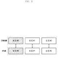
- FIG. 1 illustrates an example of a configuration of an LTE-A system where the uplink and downlink each has three component carriers.
- a reference of the aggregated component carriers is called an anchor carrier or anchor component carrier, and the others are called a non-anchor carrier or non-anchor component carrier.
- An eNode B or base station (BS) notifies user equipment (UE) of which one of the component carriers is set and managed as an anchor carrier, by performing an upper layer signaling operation.
- UE user equipment
- UE user equipment
- UE user equipment
- a component carrier set as an anchor carrier may be a reference component carrier that transmits the initial system information, performs an upper layer signaling operation, and controls user equipment mobility.
- a component carrier, performing a random access operation after user equipment first accesses a system may be an uplink anchor carrier.
- downlink and uplink are each operated via three aggregated component carriers, where a downlink component carrier, Downlink CC (DL CC) #0, and an uplink component carrier, Uplink CC (UL CC) #0, are set as anchor carriers of uplink and downlink, respectively.
- FIG. 1 shows an example of symmetrical carrier aggregation where the number of uplink component carriers is the same as the downlink component carriers; however, they can also be achieved with asymmetrical carrier aggregation where their numbers differ from each other.
- DCI Downlink Control Information
- MIMO Multiple Input Multiple Output
- the DCI is processed through channel coding and modulation, and then transmitted via Physical Downlink Control Channel (PDCCH) as a downlink physical control channel.
- PDCCH Physical Downlink Control Channel
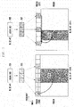
- FIG. 2 illustrates an example where a base station schedules downlink data to user equipment in an LTE-A system where two carriers, DL CC #1 and DL CC #2, are aggregated.
- DCI 201 is transmitted via downlink component carrier #1 (DL CC #1) 209.
- DCI 201 is formatted, complying with the definition of LTE, channel-coded, and interleaved, thereby forming PDCCH 203.
- PDCCH 203 informs user equipment of scheduling information regarding Physical Downlink Shared Channel (PDSCH) 213 as a data channel allocated to user equipment, via DL CC#1 (209).
- DCI 205 is transmitted via downlink component carrier #2 (DL CC #2) 211.
- PDSCH Physical Downlink Shared Channel
- DCI 205 is formatted, complying with the definition of LTE, channel-coded, and interleaved, thereby forming PDCCH 207.
- PDCCH 207 informs user equipment of scheduling information regarding PDSCH 215 as a data channel allocated to user equipment, via DL CC#2 (211).
- user equipment When user equipment is activated by the aggregation of N component carriers in LET-A system described above, if it does not receive the notification although real data is scheduled regarding only one component carrier, it must receive control channels with respect to respective component carriers in order to determine whether the N-1 component carriers are scheduled. This causes user equipment to consume electric power.
- the invention has been made in view of the above problems, and provides a system and method that can allow user equipment to deactivate the carrier aggregation in a wireless communication system that supports a wide range of bandwidth via carrier aggregation.
- the invention provides a transmission method of a base station in a mobile communication system supporting carrier aggregation, including: activating multi-carriers where a number of component carriers forming a first set are aggregated, when operating in amulti-carrier mode, and transmitting a control signal and data via the multi-carriers; activating, when the multi-carrier mode is switched to a single carrier mode, one of a number of component carriers forming a second set, deactivating the remaining component carriers in the second set, and transmitting data and a control signal with a preset carrier indicator via the single carrier; and notifying, when the single carrier mode is switched to the multi-carrier mode, user equipment of the multi-carrier mode.
- the invention provides a reception method of user equipment in a mobile communication system supporting carrier aggregation, including: receiving, when operating in a multi-carrier mode, data and a control signal related to multi-carriers where a number of component carriers forming a first set are aggregated, via the multi-carriers; and switching, when a control signal with a preset carrier indicator is received via one of a number of other component carriers forming a second set during the multi-carrier mode, the multi-carrier mode to a single carrier mode and receiving data via the single carrier.
- the invention provides a transmission device of a base station in a mobile communication system supporting carrier aggregation, the device including: a controller and a scheduler.
- the controller activates multi-carriers where a number of component carriers forming a first set are aggregated, when operating inamulti-carrier mode.
- the controller activates, when the multi-carrier mode is switched to a single carrier mode, one of a number of component carriers forming a second set.
- the controller deactivates the remaining component carriers in the second set.
- the scheduler transmits data and a control signal via the multi-carrier, during the multi-carrier mode, and data and a control signal with a preset carrier indicator via the single carrier, during the single carrier mode.
- the scheduler notifies, when the single carriermode is switched to the multi-carrier mode, user equipment of the multi-carrier mode.
- the invention provides a reception device of user equipment in a mobile communication system supporting carrier aggregation, the device including a receiver and a carrier aggregation controller.
- the receiver receives data and a control signal related to multi-carriers where a number of component carriers forming a first set are aggregated, via the multi-carriers, when operating in a multi-carrier mode, and data and a control signal via one of a number of component carriers forming a second set, when operating in a single carrier mode.
- the carrier aggregation controller switches, when a control signal with a preset carrier indicator is received via the single carrier during the multi-carrier mode, the multi-carrier mode to a single carrier mode.
- the carrier aggregation controller executes, when receiving a notification of the mode switching operation, the multi-carrier mode.
- the invention provides a system and method that rapidly enables user equipment to perform a transmission/reception operation regarding one single preset carrier, which is hereinafter called 'single component carrier fallback,' where the user equipment has been activated by setting the multi-carriers, in a wireless communication system that supports a wide range of bandwidth via carrier aggregation.
- the system and method according to the invention can perform the single component carrier fallback with a high level of reliability and without additional uplink feedback overhead, thereby minimizing electric power consumption in the user equipment.
- Multiple carriers each include a number of component carriers that are aggregated.
- one of the preset component carriers is called an anchor carrier or anchor component carrier.
- An anchor carrier is processed according to a predefined protocol between a base station and user equipment.
- the other component carriers are called non-anchor carriers or non-anchor component carriers.
- Single component carrier fallback refers to an operation where transmission/reception is performed via the anchor carrier and is stopped via non-anchor carriers.
- data transmission and DCI transmission for supporting data transmission is performed according to corresponding component carriers, as shown in FIG. 2 .
- DCI may be transmitted via component carriers for transmitting data and the other component carriers. This is described referring to FIG. 3 .
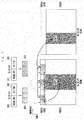
- FIG. 3 shows an example where a scheduling operation is performed in LTE-A user equipment that aggregates downlink component carrier #1 (DL CC #1) 309 and downlink component carrier #2 (DL CC #2) 319. Since downlink interference occurs in DL CC #2 (319) more often than in DL CC #1 (309), if DCI for data transmission is transmitted via DL CC #2 (319), it is difficult to achieve a certain level of DCI reception performance. In that case, the base station can transmit DCI via DL CC #1 (309). Since data errors can be corrected via HARQ re-transmission, data can be transmitted via DL CC #2 (319).
- the base station adds a carrier indicator (CI), indicating that DCI represents scheduling information regarding a component carrier, to DCI that represents the resource allocation information regarding scheduled data, the transmission format, etc.
- CI carrier indicator
- DCI 301 representing the resource allocation information regarding scheduled data 307 to DL CC #1 (309), and the transmission format, is coupled with a carrier indicator 302, thereby creating extended DCI.
- the DCI is channel-coded (303).
- the channel coded DCI 303 is processed to form PDCCH by a modulation process and an interleaving process. After that, it is mapped to the PDCCH area 305 of DL CC #1 (309) and then transmitted.
- the DCI is channel-coded (313).
- the channel coded DCI 313 is processed to form PDCCH by a modulation process and an interleaving process. After that, it is mapped to the PDCCH area 305 of DL CC #1 (309) and then transmitted.
- a specific codeword of the carrier indicator is defined to report the 'single component carrier fallback.
- the control information to report a 'single component carrier fallback' may be defined separately from the carrier indicator. This is described referring to FIG. 4 .
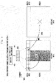
- FIG. 4 shows an example where user equipment, where DL CC #1 (411) and DL CC #2 (413) are activated, performs a 'single component carrier fallback' via a carrier indicator and DCI of the DL CC #1 (411).
- the base station instructs the single component carrier fallback in various states according to the determination of the scheduler. Examples of the states are a case where the base station does not have sufficient data to be transmitted to user equipment or available system resources.
- base station maps the PDCCH to the PDCCH area 405 of the DL CC #1 (411) and transmits it.
- DCI 400 indicates scheduling information regarding data 407 of DL CC #1.
- a multi-carrier mode refers to a transmission/reception operation via multi-carriers where a number of component carriers are aggregated.
- a single carrier mode refers to a transmission/reception operation via one of the components, i.e., an anchor carrier.
- Each component carrier includes a control channel and a data channel.
- the reception operation includes a control reception operation for the control channel and a data reception operation for the data channel.
- user equipment where multi-carriers are activated performs the deactivation via a 'single component carrier fallback' command and performs a single carrier mode, in an LTE-A system supporting carrier aggregation.
- User equipment performs downlink control information via extended DCI that always includes CI, regardless of whether user equipment performs a multi-carrier mode or a single carrier mode.
- Embodiment 1 has a feature that does not require, from the user equipment, a feedback indicating whether the user equipment has successfully received a 'single component carrier fallback.'
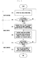
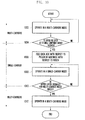
- FIG. 5 illustrates a first embodiment of a procedure where a base station allows user equipment to switch the mode from the current multi-carrier mode to a single carrier mode and then to the multi-carrier mode, via the 'single component carrier fallback.
- the base station activates multi-carriers with respect to user equipment to be scheduled.
- the base station determines whether it can support carrier aggregation of the user equipment, and notifies the user equipment of the number of component carriers to be aggregated and the activation state of multi-carriers including the type of component carrier to be aggregated and the determination as to whether a multi-carrier mode is performed.
- the base station determines whether to allow the user equipment to maintain the activation state of multi-carriers or to deactivate the activation and to switch the current mode to a single carrier mode to receive data via only a preset anchor carrier. For example, when the base station does not have sufficient data to be transmitted to the user equipment or the available system resources, it instructs the user equipment to perform a single carrier mode. When the base station allows the user equipment to maintain the activation state of multi-carriers at step 504, it returns to and proceeds with step 502.
- the base station when the base station allows the user equipment to operate in a single carrier mode at step 504, it sets the carrier indicator for the user equipment as a value preset as a 'single component carrier fallback,' and creates extended DCI by adding DCI for scheduling data transmitted via an anchor carrier, at step 506.
- the extended DCI is channel-decoded, modulated and interleaved, thereby creating PDCCH.
- the PDCCH is transmitted to the user equipment via the anchor carrier.
- the base station when the base station intends to schedule data additionally transmitted via an anchor carrier, with respect to the user equipment, it creates extended DCI by aggregating a carrier indicator, set to instruct a 'single component carrier fallback,' with DCI for scheduling data transmitted via an anchor carrier.
- the extended DCI is channel-decoded, modulated and interleaved, thereby creating PDCCH.
- the PDCCH is transmitted to the user equipment via the anchor carrier.
- the user equipment does not receive PDCCH and thus immediately detects the 'single component carrier fallback' at step 506, it has an additional opportunity to successfully acquire the 'single component carrier fallback' at step 508.
- the base station does not request the feedback from the user equipment if it has received the 'single component carrier fallback,' thereby minimizing the additional signal overhead.
- the base station determines whether to allow the user equipment to maintain the single carrier mode or to reactivate the multi-carrier mode. If the base station has sufficient data to be transmitted to the user equipment or a sufficient amount of available system resources, it instructs the user equipment to reactivate multi-carriers. When the base station allows the user equipment to maintain the single carrier mode at step 510, it returns to and proceeds with step 508. On the contrary, when the base station allows the user equipment to reactivate the multi-carrier mode at step 510, it notifies the user equipment of the specific activation state for the multi-carrier mode by an upper layer signaling operation at step 512. The notification procedure will be described, in detail, later, referring to FIG. 7 .
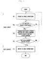
- FIG. 6 illustrates a first embodiment of a procedure where user equipment switches the current multi-carrier mode to a single carrier mode and then to the multi-carrier mode, according to instructions from a base station.
- the user equipment activates the multi-carriers according to the command from the base station at step 602.
- the user equipment receives PDCCH from the base station and determines whether the carrier indicator is set to a 'single component carrier fallback.' When the user equipment ascertains that the carrier indicator is not set to a 'single component carrier fallback' at step 604, it returns to and proceeds with step 602.
- the user equipment when the user equipment ascertains that the carrier indicator is set to a 'single component carrier fallback' at step 604, it stops receiving data via the remaining component carriers other than the anchor carrier and operates in a single carrier mode at step 606. In that case, the user equipment does not transmit, to the base station, a feedback whether it has successfully received the ⁇ single component carrier fallback' command; however, it transmits, to the base station, an ACK/NACK feedback indicating whether there is error in data received via PDSCH.
- the user equipment determines whether to reactivate multi-carrier mode via an upper layer signaling operation from the base station at step 608.
- the user equipment determines whether to reactivate multi-carrier mode via an upper layer signaling operation from the base station at step 608.
- the user equipment when the user equipment ascertains that a multi-carrier mode is reactivated at step 608, it operates in a multi-carrier mode according to the command from the base station at step 610.
- the user equipment According to the commands for activating a multi-carrier mode from the base station, the user equipment operates in the mode, which will be described, in detail, referring to FIG. 8 .
- the base station In order to allow user equipment to switch the operation mode from the single carrier mode to a multi-carrier mode according to a 'single component carrier fallback,' the base station, described referring to FIGS. 5 and 6 , reactivates the multi-carrier mode by an upper layer signaling operation.
- the operation can also be achieved by the following methods.
- Method 1 When a base station reactivates a multi-carrier mode of user equipment, it configures extended DCI, via DCI serving as scheduling information regarding data transmitted via an anchor carrier, and a carrier indicator indicating component carriers to be activated.
- the base station creates PDCCH based on the extended DCI, and transmits it to the user equipment, via the anchor carrier and a PHSCH serving as a dedicated channel for scheduled data transmission.
- the user equipment feed basks the base station an ACK/NACK signal indicating whether to successfully receive the PDSCH, and then operates in a multi-carrier mode. After successfully receiving the PDSCH, the user equipment can decode it.
- the base station receives a feedback of ACK/NACK regarding the PDSCH from the user equipment, it can detect that the user equipment has successfully received the PDCCH and thus operates in a multi-carrier mode.
- Method 2 When the base station reactivates a multi-carrier mode of user equipment, it configures extended DCI by coupling a carrier indicator, indicating a component carrier to be activated, with a preset pattern.
- the preset pattern is used as virtual cyclic redundancy check (CRC) and reinforces an error detection ability regarding the extended DCI. That is, the pattern can be used to minimize the possibility that user equipment detects the extended DCI in error and activates multi-carriers, although the base station didn't instruct the user equipment to activate multi-carriers.
- the extended DCI doesn't include resource allocation information regarding data that the base station will transmit, scheduling information, transmission format, etc.
- the user equipment When the user equipment has successfully received the extended DCI via the PDCCH, it transmits ACK to the base station and operates in a multi-carrier mode. On the contrary, when the user equipment fails to receive the extended DCI via the PDCCH, it doesn't feed back and maintains operating in a single carrier mode. Only if the base station receives ACK for the PDCCH from the user equipment, it detects that the user equipment switches the mode to a multi-carrier mode.
- Method 3 The base station defines a specific codeword of a carrier indicator, included in extended DCI, as a 'multi-carrier re-activation' command.
- user equipment When user equipment receives a 'multi-carrier re-activation' command, it switches the mode to a multi-carrier setting state immediately before being switched to a single carrier mode.
- a multi-carrier mode including DL CC #1, DL CC #2, DL CC #3, and DL CC #4, immediately before being switched to a single carrier mode, it can re-operate the multi-carrier mode including DL CC #1, DL CC #2, DL CC #3, and DL CC #4, according to the 'multi-carrier re-activation' command.
- the base station When the base station creates extended DCI, via DCI regarding data scheduled via an anchor carrier, and transmits the extended DCI and the 'multi-carrier re-activation' command to user equipment via PDCCH, the user equipment feeds back the base station anACK/NCK regarding PDSCH, accompanied by the PDCCH, thereby informing the base station of the successful reception of the 'multi-carrier re-activation' command.
- the base station creates extended DCI by coupling the 'multi-carrier re-activation' command with a preset pattern, and transmits it via PDCCH.
- the extended DCI doesn't include resource allocation information regarding data that the base station will transmit, scheduling information, transmission format, etc. In that case, only if the base station receives ACK for the PDCCH from the user equipment, it detects that the user equipment switches the mode to a multi-carrier mode.
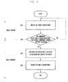
- FIG. 7 illustrates a first embodiment of a procedure of Methods 1, 2, and 3, described above, where the base station enables the user equipment to switch the current single carrier mode to a multi-carrier mode, according to a 'single component carrier fallback' command.
- the current base station allows user equipment to be scheduled to operate in a single carrier mode.
- the base station determines whether to allow the user equipment to maintain the single carrier mode or to reactivate a multi-carrier mode. For example, if the base station has sufficient data to be transmitted to the user equipment or a sufficient amount of available system resources, it instructs the user equipment to reactivate a multi-carrier mode. When the base station allows the user equipment to maintain the single carrier mode at step 704, it returns to and proceeds with step 702.
- the base station when the base station allows the user equipment to reactivate a multi-carrier mode at step 704, it configures extended DCI, via a 'multi-carrier reactivation' command or a carrier indicator that indicates component carriers to be activated, instead of a 'single component carrier fallback' command, and transmits it via PDCCH, at step 706.
- the extendedDCI includes scheduling information regarding data scheduled via an anchor carrier
- the base station additionally transmits the scheduled data via PDSCH.
- the base station determines whether the user equipment has successfully received the extended DCI. If the base station has transmitted PDSCH and received ACK/NACK regarding the PDSCH from the user equipment at step 706, it detects whether the user equipment has successfully received the extended DCI according to the ACK/NACK. If the base station has not scheduled PDSCH at step 706 but receives ACK regarding PDCCH, through which the extended DCI is transmitted, from the user equipment, it detects that the user equipment has successfully received the extended DCI. When the base station ascertains that the user equipment fails to receive the extended DCI at step 708, it returns to and proceeds with step 704. On the contrary, when the base station ascertains that the user equipment has successfully received the extended DCI at step 708, it executes a multi-carrier mode with respect to the user equipment at step 710.
- FIG. 8 illustrates a first embodiment of a procedure of Methods 1, 2, and 3, described above, where the user equipment switches the mode from a single carrier mode to a multi-carrier mode, according to a 'single component carrier fallback' command.
- the user equipment stops receiving data via the remaining component carriers other than the anchor carrier and operates in a single carrier mode.
- the user equipment determines whether to receive a carrier indicator that indicates a specific component carrier or a 'multi-carrier reactivation' command, instead of a 'single component carrier fallback' command, from the base station, via PDCCH.
- a carrier indicator that indicates a specific component carrier or a 'multi-carrier reactivation' command
- the user equipment has received a 'single component carrier fallback' command or fails to receive data via PDCCH at step 804, it returns to and proceeds with step 802.
- the user equipment when the user equipment has received a carrier indicator or a 'multi-carrier reactivation' command at step 804, it identifies whether the received PDCCH data includes scheduling information regarding data at step 806.
- the user equipment when the user equipment ascertains that the received PDCCH data includes scheduling information, it feeds back the base station an ACK or NACK signal indicating whether the data has been successfully received via PDSCH or not.
- the user equipment when the user equipment ascertains that the received PDCCH data doesn't include scheduling information, it feeds back the base station an ACK.
- step 808 when the user equipment activates a component carrier, indicated by a carrier indicator received via the PDCCH, or a 'multi-carrier reactivation' command via the PDCCH, it switches the mode to a multi-carrier state immediately before executing a 'single component carrier fallback.
- user equipment where multi-carriers are activated performs the deactivation and performs a single carrier mode, in an LTE-A system supporting carrier aggregation.
- User equipment transmits downlink control information: via extended DCI including carrier indicators (CIs), in a multi-carrier mode; and via usual DCI that does not include CIs, in a single carrier mode.
- embodiment 2 has a feature that requires, the user equipment, a feedback indicating whether the user equipment has successfully received a 'single component carrier fallback.'
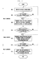
- FIG. 9 illustrates a second embodiment of a procedure where a base station allows user equipment to switch the mode from the current multi-carrier mode to a single carrier mode and then to the multi-carrier mode, via the 'single component carrier fallback.
- the base station activates multi-carriers with respect to user equipment to be scheduled.
- the base station determines whether it can support carrier aggregation of the user equipment, and notifies the user equipment of the number of component carriers to be aggregated and the activation state of multi-carriers including the type of component carrier to be aggregated and the determination as to whether a multi-carrier mode is performed.
- the base station determines whether to allow the user equipment to maintain the activation state of multi-carriers or to deactivate the activation and to switch the current mode to a single carrier mode to receive data via only a preset anchor carrier. For example, when the base station does not have sufficient data to be transmitted to the user equipment or the available system resources, it instructs the user equipment to perform a single carrier mode. When the base station allows the user equipment to maintain the activation state of multi-carriers at step 904, it returns to and proceeds with step 902.
- the base station when the base station allows the user equipment to operate in a single carrier mode at step 904, it sets the carrier indicator for the user equipment as a value preset as a 'single component carrier fallback,' and creates extended DCI at step 906.
- the extended DCI is channel-decoded, modulated and interleaved, thereby creating PDCCH.
- the PDCCH is transmitted to the user equipment via the anchor carrier.
- the extended DCI includes DCI, serving as scheduling information regarding data scheduled via an anchor carrier, or a preset pattern instead of scheduling information regarding data.
- the base station If the extended DCI includes DCI serving as scheduling information regarding data scheduled via an anchor carrier, the base station additionally transmits the scheduled data via PDSCH.
- the preset pattern is used as virtual cyclic redundancy check (CRC) and reinforces an error detection ability regarding the extended DCI. That is, the pattern can be used to minimize the possibility that user equipment detects the extended DCI in error and operates in a single carrier mode, although the base station didn't instruct the user equipment to execute a 'single component carrier fallback' command.
- CRC virtual cyclic redundancy check
- the base station determines whether the user equipment has successfully received extended DCI including the 'single component carrier fallback' command. If the base station has transmitted PDSCH and received ACK/NACK regarding the PDSCH from the user equipment at step 906, it detects whether the user equipment has successfully received the extended DCI according to the ACK/NACK. If the base station has not scheduled PDSCH at step 906 but receives ACK regarding PDCCH, through which the extended DCI is transmitted, from the user equipment, it detects that the user equipment has successfully received the extended DCI. When the base station ascertains that the user equipment fails to receive the extended DCI at step 908, it returns to and proceeds with step 906. On the contrary, when the base station ascertains that the user equipment has successfully received the extended DCI at step 908, it executes a single carrier mode with respect to the user equipment at step 910.
- the base station when the base station intends to schedule data additionally transmitted via an anchor carrier, with respect to the user equipment, it creates downlink control information by only DCI for scheduling data transmitted via the anchor carrier without a carrier indicator.
- the created downlink control information is channel-coded, modulated, and interleaved, thereby creating PDCCH.
- the PDCCH is transmitted to the user equipment via the anchor carrier.
- the base station determines whether to allow the user equipment to maintain the single carrier mode or to reactivate the multi-carrier mode. If the base station has sufficient data to be transmitted to the user equipment or a sufficient amount of available system resources, it instructs the user equipment to reactivate multi-carriers. When the base station allows the user equipment to maintain the single carrier mode at step 912, it returns to and proceeds with step 910.
- the base station when the base station allows the user equipment to reactivate the multi-carrier mode at step 912, it notifies the user equipment of the specific activation state for the multi-carrier mode by an upper layer signaling operation at step 914.
- the notification procedure will be described, in detail, later, referring to FIG. 11 .
- FIG. 10 illustrates a second embodiment of a procedure where user equipment switches the current multi-carrier mode to a single carrier mode and then to the multi-carrier mode, according to instructions from a base station.
- the user equipment activates the multi-carriers according to the command from the base station at step 1002.
- the user equipment receives PDCCH from the base station and determines whether the carrier indicator is set to a 'single component carrier fallback.' When the user equipment ascertains that the carrier indicator is not set to a 'single component carrier fallback' at step 1004, it returns to and proceeds with step 1002.
- the user equipment when the user equipment ascertains that the carrier indicator is set to a 'single component carrier fallback' at step 1004, it identifies whether the received PDCCH data includes scheduling information regarding data at step 1006.
- the user equipment when the user equipment ascertains that the received PDCCH data includes scheduling information, it feeds back the base station an ACK or NACK signal indicating whether the data has been successfully received via PDSCH or not.
- the user equipment when the user equipment ascertains that the received PDCCH data doesn' t include scheduling information, it feeds back the base station an ACK.
- the user equipment stops receiving data via the remaining component carriers other than the anchor carrier and operates in a single carrier mode.
- the user equipment determines whether to reactivate multi-carrier mode via an upper layer signaling operation from the base station at step 1010.
- the user equipment determines whether to reactivate multi-carrier mode via an upper layer signaling operation from the base station at step 1010.
- the user equipment when the user equipment ascertains that a multi-carrier mode is reactivated at step 1010, it operates in a multi-carrier mode according to the command from the base station at step 1012. According to the commands for activating a multi-carrier mode from the base station, the user equipment operates in the mode, which will be described, in detail, referring to FIG. 12 .
- the base station In order to allow user equipment to switch the operation mode from the single carrier mode to a multi-carrier mode according to a 'single component carrier fallback,' the base station, described referring to FIGS. 9 and 10 , reactivates the multi-carrier mode by an upper layer signaling operation. In addition, the operations can also be achieved by the following embodiments described in FIGS. 11 and 12 .
- FIG. 11 illustrates a second embodiment of a procedure where the base station enables the user equipment to switch the current single carrier mode to a multi-carrier mode, according to a 'single component carrier fallback' command.
- the current base station allows user equipment to be scheduled to operate in a single carrier mode.
- the base station determines whether to allow the user equipment to maintain the single carrier mode or to reactivate a multi-carrier mode. For example, if the base station has sufficient data to be transmitted to the user equipment or a sufficient amount of available system resources, it instructs the user equipment to reactivate a multi-carrier mode. When the base station allows the user equipment to maintain the single carrier mode at step 1104, it returns to and proceeds with step 1102.
- the base station when the base station allows the user equipment to reactivate a multi-carrier mode at step 1104, it must use usual DCI without a carrier indicator, as downlink control information, during the single carrier mode at 1106. In that case, the base station instructs the user equipment to return to the multi-carrier mode, by fixing part of the DCI to a preset pattern or all of the DCI to a preset pattern to reinforce the error detection. If part of the DCI is fixed to a preset pattern, the base station informs the user equipment of scheduling information regarding data scheduled via an anchor carrier, via the remaining DCI areas, and then transmits the scheduled data via PDSCH. If all of the DCI is fixed to a preset pattern, the base station doesn't schedule data.
- the base station determines whether the user equipment has successfully received the DCI. If the base station has transmitted PDSCH and received ACK/NACK regarding the PDSCH from the user equipment at step 1106, it detects whether the user equipment has successfully received the DCI according to the ACK/NACK. If the base station has not scheduled PDSCH at step 1106 but receives ACK regarding PDCCH, through which the DCI is transmitted, from the user equipment, it detects that the user equipment has successfully received the DCI. When the base station ascertains that the user equipment fails to receive the DCI at step 1108, it returns to and proceeds with step 1106.
- the base station executes a multi-carrier mode with respect to the user equipment at step 1110.
- the user equipment switches the mode to a multi-carrier setting state immediately before being switched to a single carrier mode.
- the user equipment when the user equipment has been operated a multi-carrier mode including DL CC #1, DL CC #2, DL CC #3, and DL CC #4, immediately before being switched to a single carrier mode, it can re-operate the multi-carrier mode including DL CC #1, DL CC #2, DL CC #3, and DL CC #4, at step 1110.
- FIG. 12 illustrates a second embodiment of a procedure where the user equipment switches the mode from a single carrier mode to a multi-carrier mode, according to a 'single component carrier fallback' command.
- the user equipment stops receiving data via the remaining component carriers other than the anchor carrier and operates in a single carrier mode.
- the user equipment detects DCI from PDCCH transmitted from the base station. If the user equipment ascertains that the DCI is not set to a preset pattern to notify the base station of the switching operation to a multi-carrier mode, it returns to and proceeds with step 1202.
- the user equipment if the user equipment ascertains that par or all of the DCI is set to a preset pattern to notify the base station of the switching instruction to a multi-carrier mode, it detects that it must return to a multi-carrier mode at step 1206. That is, the user equipment identifies whether the received PDCCH data includes scheduling information regarding data at step 1206. When the user equipment ascertains that the received PDCCH data includes scheduling information, it feeds back the base station an ACK or NACK signal indicating whether the data has been successfully received via PDSCH or not. On the contrary, when the user equipment ascertains that the received PDCCH data doesn' t include scheduling information, it feeds back the base station an ACK.
- step 1208 the user equipment witches the mode to a multi-carrier state immediately before executing a 'single component carrier fallback.
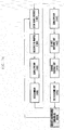
- FIG. 13 illustrates a configuration of a base station according to the invention.
- the base station includes a carrier aggregation controller 1302, a scheduler 1304, a number of DCI processors 1312 and 1314, a multiplexer 1316, a scrambler 1318, a modulator 1320, a resource mapper 1322, and an OFDM signal creator 1324.
- a DCI processor 1312 one of a number of DCI processors 1312 and 1314, is related to user equipment, UE #1, and includes a DCI creating unit 1306, a channel coding unit 1308, and a rate matching unit 1310.
- the other DCI processors 1314, related to UE #2 to UE #N, have the same components as DCI processor 1312 for UE #1.
- the carrier aggregation controller 1302 determines the carrier aggregation with respect to user equipment to be scheduled, referring to amount of data to be transmitted to user equipment and the amount of available system resources, and informs the scheduler 1304 of the determination. If the carrier aggregation controller 1302 intends to notify UE #1 operating in a multi-carrier mode of the determination of a 'single component carrier fallback,' the scheduler 1304 controls the DCI creating unit 1306 to configure extended DCI by setting a carrier indicator to a preset codeword for a 'single component carrier fallback.' The extended DCI is equipped with an error correction ability by the channel coding unit 1308, rate-matched by the rate matching unit 1310 with the amount of mapped resources to be mapped, and multiplexed with DCI of the other user equipment by the multiplexer 1316.
- the multiplexed signal is processed via the scrambler 1318 and the modulator 1320 and mapped to time-frequency resources to be transmitted by the resource mapper 1322.
- the OFDM signal creator 1324 creates an OFDM signal from the mapped signal and transmits it to the user equipment.
- FIG. 14 illustrates a configuration of user equipment according to the invention.
- the user equipment includes an OFDM signal receiver 1402, a resource re-mapper 1404, a demultiplexer 1406, a descrambler 1408, a demultiplexer 1410, a de-rate matching unit 1412, a channel decoding unit 1414, a DCI acquiring unit 1416, and a carrier aggregation controller 1418.
- the OFDM signal receiver 1402 receives signal from the base station.
- the resource re-mapper 1404 extracts PDCCH from the signals received by the OFDM signal receiver 1402.
- the demultiplexer 1406 and the descrambler 1408 process the PDCCH.
- the demultiplexer 1410 extracts corresponding allocated PDCCH from the processed PDCCH from the descrambler 1408.
- the de-rate-matching unit 1412 re-rate-matches the PDCCH extracted by the user equipment.
- the channel decoding unit 1414 decodes the re-rate-matched PDCCH.
- the DCI acquiring unit 1416 extracts DCI from the decoded result.
- the DCI is output to the carrier aggregation controller 1418 and used to control the carrier aggregation state of the user equipment. If the DCI indicates a 'single component carrier fallback,' the carrier aggregation controller 1418 controls the OFDM signal receiver 1402 to receive data via only an anchor carrier, thereby reducing
- the embodiment where the base station instructs user equipment to operate according to the 'single component carrier fallback' may be modified in such a way that the base station can define part or all of the extended DCI to be transmitted to a preset pattern and deactivates a specific component carrier indicated by a carrier indicator.
- the system and method according to the invention can allow user equipment to rapidly deactivate the carrier aggregation in a wireless communication system that supports a wide range of bandwidth via carrier aggregation, thereby reducing electric power consumption in the user equipment.
Landscapes
- Engineering & Computer Science (AREA)
- Signal Processing (AREA)
- Computer Networks & Wireless Communication (AREA)
- Mobile Radio Communication Systems (AREA)
- Transceivers (AREA)
Applications Claiming Priority (2)
| Application Number | Priority Date | Filing Date | Title |
|---|---|---|---|
| KR1020090093978A KR101699860B1 (ko) | 2009-10-01 | 2009-10-01 | 셀룰러 무선 통신시스템에서 단말의 반송파 결합 활성화 여부를 지시하는 방법 및 장치 |
| PCT/KR2010/006687 WO2011040777A2 (ko) | 2009-10-01 | 2010-09-30 | 셀룰러 무선 통신시스템에서 단말의 반송파 결합 활성화 여부를 지시하는 방법 및 장치 |
Publications (2)
| Publication Number | Publication Date |
|---|---|
| EP2485518A2 true EP2485518A2 (de) | 2012-08-08 |
| EP2485518A4 EP2485518A4 (de) | 2017-05-17 |
Family
ID=43826801
Family Applications (1)
| Application Number | Title | Priority Date | Filing Date |
|---|---|---|---|
| EP10820850.5A Withdrawn EP2485518A4 (de) | 2009-10-01 | 2010-09-30 | Verfahren und vorrichtung zur anzeige der aktivierung einer endgeräteträgeraggregation in einem drahtlosen zellkommunikationssystem |
Country Status (4)
| Country | Link |
|---|---|
| US (1) | US9036549B2 (de) |
| EP (1) | EP2485518A4 (de) |
| KR (1) | KR101699860B1 (de) |
| WO (1) | WO2011040777A2 (de) |
Cited By (1)
| Publication number | Priority date | Publication date | Assignee | Title |
|---|---|---|---|---|
| CN109728890A (zh) * | 2013-06-27 | 2019-05-07 | 华为技术有限公司 | 载波切换方法、基站和用户设备 |
Families Citing this family (14)
| Publication number | Priority date | Publication date | Assignee | Title |
|---|---|---|---|---|
| KR20110090521A (ko) * | 2010-02-04 | 2011-08-10 | 주식회사 팬택 | 무선통신 시스템에서 데이터 및 제어정보의 전송 방법 및 그 송신장치, 그 수신장치 |
| US9319177B2 (en) * | 2011-05-11 | 2016-04-19 | Intel Deutschland Gmbh | Radio communication devices and methods for controlling a radio communication device |
| DE102013108279B4 (de) * | 2012-08-02 | 2019-03-21 | Intel Deutschland Gmbh | Funkkommunikationseinrichtungen und Verfahren zum Steuern einer Funkkommunikationseinrichtung |
| KR20150012705A (ko) * | 2013-07-26 | 2015-02-04 | 주식회사 팬택 | 단말에서 전류 소모 감소를 위한 방법 및 장치 |
| US9585153B2 (en) * | 2014-12-18 | 2017-02-28 | Alcatel-Lucent Usa Inc. | Method and apparatus for improved carrier aggregation access control |
| CN107710655B (zh) * | 2015-08-07 | 2019-06-28 | 三菱电机株式会社 | 发送装置、接收装置、发送方法以及接收方法 |
| KR102138111B1 (ko) * | 2015-11-30 | 2020-07-27 | 후아웨이 테크놀러지 컴퍼니 리미티드 | 스케줄링 장치, 피스케줄링 장치, 및 자원 스케줄링 방법과 장치 |
| US20170238284A1 (en) * | 2016-02-05 | 2017-08-17 | Mediatek Inc. | Multi-Carrier Operation for Narrowband Internet of Things |
| US10644827B2 (en) * | 2017-04-06 | 2020-05-05 | Qualcomm Incorporated | Systems and methods for dynamic switching between waveforms on downlink |
| US10841808B2 (en) * | 2017-10-16 | 2020-11-17 | Apple Inc. | Apparatus and medium for enabling multi-carrier operation |
| CN110719635B (zh) * | 2018-07-13 | 2021-09-17 | 维沃移动通信有限公司 | 一种信道检测指示方法、终端及网络设备 |
| KR102710392B1 (ko) * | 2019-07-26 | 2024-09-26 | 삼성전자주식회사 | 다중 연결 환경에서 안테나 최적화 방법 및 이를 이용하는 전자 장치 |
| US11877290B2 (en) | 2020-04-06 | 2024-01-16 | Qualcomm Incorporated | Parallel uplink control channels in uplink carrier aggregation |
| US11368944B2 (en) * | 2020-04-06 | 2022-06-21 | Qualcomm Incorporated | Parallel duplicated uplink control channels in uplink carrier aggregation |
Family Cites Families (7)
| Publication number | Priority date | Publication date | Assignee | Title |
|---|---|---|---|---|
| US6535739B1 (en) * | 2000-04-07 | 2003-03-18 | Qualcomm Incorporated | Method of handoff within a telecommunications system containing digital base stations with different spectral capabilities |
| US20020127982A1 (en) * | 2001-03-07 | 2002-09-12 | Nokia Mobile Phones Ltd | Mobile station receiver operable for both single and multi-carrier reception |
| JP4527067B2 (ja) * | 2005-03-31 | 2010-08-18 | 株式会社エヌ・ティ・ティ・ドコモ | 移動局、送信方法及び移動通信システム |
| US7957351B2 (en) * | 2005-04-04 | 2011-06-07 | Qualcomm Incorporated | Method and apparatus for management of multi-carrier communications in a wireless communication system |
| KR101537607B1 (ko) * | 2008-02-05 | 2015-07-29 | 엘지전자 주식회사 | 조정필드를 이용한 효율적인 무선채널 전송방법 |
| KR101276848B1 (ko) * | 2008-07-17 | 2013-06-18 | 엘지전자 주식회사 | 멀티 캐리어를 이용하는 통신시스템에서 전력절감을 위한 데이터 송수신 방법 및 장치 |
| WO2010146673A1 (ja) * | 2009-06-17 | 2010-12-23 | 富士通株式会社 | 通信装置、通信システムおよび通信方法 |
-
2009
- 2009-10-01 KR KR1020090093978A patent/KR101699860B1/ko not_active Expired - Fee Related
-
2010
- 2010-09-30 EP EP10820850.5A patent/EP2485518A4/de not_active Withdrawn
- 2010-09-30 US US13/499,897 patent/US9036549B2/en active Active
- 2010-09-30 WO PCT/KR2010/006687 patent/WO2011040777A2/ko not_active Ceased
Non-Patent Citations (1)
| Title |
|---|
| See references of WO2011040777A2 * |
Cited By (2)
| Publication number | Priority date | Publication date | Assignee | Title |
|---|---|---|---|---|
| CN109728890A (zh) * | 2013-06-27 | 2019-05-07 | 华为技术有限公司 | 载波切换方法、基站和用户设备 |
| US11229026B2 (en) | 2013-06-27 | 2022-01-18 | Huawei Technologies Co., Ltd. | Carrier switching method, base station, and user equipment |
Also Published As
| Publication number | Publication date |
|---|---|
| WO2011040777A3 (ko) | 2011-08-18 |
| EP2485518A4 (de) | 2017-05-17 |
| US9036549B2 (en) | 2015-05-19 |
| WO2011040777A2 (ko) | 2011-04-07 |
| KR20110036786A (ko) | 2011-04-11 |
| KR101699860B1 (ko) | 2017-01-25 |
| US20120250625A1 (en) | 2012-10-04 |
Similar Documents
| Publication | Publication Date | Title |
|---|---|---|
| US9036549B2 (en) | Method and device for indicating whether terminal carrier aggregation has been activated in a cellular wireless communication system | |
| US12199763B2 (en) | Transport block mapping across slots | |
| KR102898989B1 (ko) | 무선 통신 시스템에서 우선 순위 기반 제어 및 데이터 정보 전송 방법 및 장치 | |
| US12010665B2 (en) | Method and apparatus for transmitting and receiving information for providing plurality of communication services | |
| US12501410B2 (en) | Transport block mapping across slots | |
| KR102366007B1 (ko) | 무선 통신 시스템에서 하향링크 제어 채널 수신 시간 설정 방법 및 장치 | |
| EP3278604B1 (de) | Überwachung eines schmalbandigen steuerkanals für ein breitbandsystem zur reduzierung des stromverbrauchs | |
| CN108111275B (zh) | 参考信号信息的配置方法及装置 | |
| JP4863027B2 (ja) | 通信システム | |
| KR101962245B1 (ko) | 광대역 단말과 협대역 단말을 함께 운용하는 무선통신시스템에서 협대역 단말의 시스템 접속 방법 및 장치 | |
| CN102907160B (zh) | 移动通信系统、基站装置、移动站装置以及通信方法 | |
| KR20210134430A (ko) | 준지속적 스케줄링을 위한 장치 및 방법 | |
| KR102339902B1 (ko) | 무선 셀룰라 통신 시스템에서 제어 정보 전송 방법 및 장치 | |
| JP6338527B2 (ja) | フィードバック情報の転送方法、システム及び設備 | |
| JP2015181267A (ja) | 通信方法、通信装置および集積回路 | |
| KR20140032476A (ko) | 무선 통신의 제어 채널 | |
| KR102878236B1 (ko) | 사용자 장비들, 기지국들 및 방법들 | |
| US11457463B2 (en) | Resource scheduling using puncturing techniques for data transmission | |
| EP4120598A2 (de) | Transportblockabbildung über schlitze | |
| WO2022208472A1 (en) | Dynamic pucch repetition via periodic csi |
Legal Events
| Date | Code | Title | Description |
|---|---|---|---|
| PUAI | Public reference made under article 153(3) epc to a published international application that has entered the european phase |
Free format text: ORIGINAL CODE: 0009012 |
|
| 17P | Request for examination filed |
Effective date: 20120330 |
|
| AK | Designated contracting states |
Kind code of ref document: A2 Designated state(s): AL AT BE BG CH CY CZ DE DK EE ES FI FR GB GR HR HU IE IS IT LI LT LU LV MC MK MT NL NO PL PT RO SE SI SK SM TR |
|
| RAP1 | Party data changed (applicant data changed or rights of an application transferred) |
Owner name: SAMSUNG ELECTRONICS CO., LTD. |
|
| DAX | Request for extension of the european patent (deleted) | ||
| A4 | Supplementary search report drawn up and despatched |
Effective date: 20170418 |
|
| RIC1 | Information provided on ipc code assigned before grant |
Ipc: H04L 5/00 20060101AFI20170410BHEP |
|
| STAA | Information on the status of an ep patent application or granted ep patent |
Free format text: STATUS: EXAMINATION IS IN PROGRESS |
|
| 17Q | First examination report despatched |
Effective date: 20180305 |
|
| RIN1 | Information on inventor provided before grant (corrected) |
Inventor name: KIM, YOUNG-BUM Inventor name: CHO, JOON-YOUNG Inventor name: KIM, YOUN-SUN Inventor name: HAN, JIN-KYU Inventor name: CHOI, SEUNG-HOON |
|
| GRAP | Despatch of communication of intention to grant a patent |
Free format text: ORIGINAL CODE: EPIDOSNIGR1 |
|
| STAA | Information on the status of an ep patent application or granted ep patent |
Free format text: STATUS: GRANT OF PATENT IS INTENDED |
|
| INTG | Intention to grant announced |
Effective date: 20210723 |
|
| STAA | Information on the status of an ep patent application or granted ep patent |
Free format text: STATUS: THE APPLICATION IS DEEMED TO BE WITHDRAWN |
|
| 18D | Application deemed to be withdrawn |
Effective date: 20211203 |