EP2485409B1 - Sélection d'antenne et apprentissage utilisant une matrice d'étalement spatial destinée à être utilisé dans un système de communication sans fil à entrées et sorties multiples - Google Patents
Sélection d'antenne et apprentissage utilisant une matrice d'étalement spatial destinée à être utilisé dans un système de communication sans fil à entrées et sorties multiples Download PDFInfo
- Publication number
- EP2485409B1 EP2485409B1 EP12003035.8A EP12003035A EP2485409B1 EP 2485409 B1 EP2485409 B1 EP 2485409B1 EP 12003035 A EP12003035 A EP 12003035A EP 2485409 B1 EP2485409 B1 EP 2485409B1
- Authority
- EP
- European Patent Office
- Prior art keywords
- matrix
- channel
- chains
- full
- data streams
- Prior art date
- Legal status (The legal status is an assumption and is not a legal conclusion. Google has not performed a legal analysis and makes no representation as to the accuracy of the status listed.)
- Active
Links
Images


Classifications
-
- H—ELECTRICITY
- H04—ELECTRIC COMMUNICATION TECHNIQUE
- H04B—TRANSMISSION
- H04B7/00—Radio transmission systems, i.e. using radiation field
- H04B7/02—Diversity systems; Multi-antenna system, i.e. transmission or reception using multiple antennas
- H04B7/04—Diversity systems; Multi-antenna system, i.e. transmission or reception using multiple antennas using two or more spaced independent antennas
- H04B7/0413—MIMO systems
- H04B7/0417—Feedback systems
-
- H—ELECTRICITY
- H04—ELECTRIC COMMUNICATION TECHNIQUE
- H04B—TRANSMISSION
- H04B7/00—Radio transmission systems, i.e. using radiation field
- H04B7/02—Diversity systems; Multi-antenna system, i.e. transmission or reception using multiple antennas
- H04B7/04—Diversity systems; Multi-antenna system, i.e. transmission or reception using multiple antennas using two or more spaced independent antennas
- H04B7/06—Diversity systems; Multi-antenna system, i.e. transmission or reception using multiple antennas using two or more spaced independent antennas at the transmitting station
- H04B7/0613—Diversity systems; Multi-antenna system, i.e. transmission or reception using multiple antennas using two or more spaced independent antennas at the transmitting station using simultaneous transmission
- H04B7/0615—Diversity systems; Multi-antenna system, i.e. transmission or reception using multiple antennas using two or more spaced independent antennas at the transmitting station using simultaneous transmission of weighted versions of same signal
- H04B7/0619—Diversity systems; Multi-antenna system, i.e. transmission or reception using multiple antennas using two or more spaced independent antennas at the transmitting station using simultaneous transmission of weighted versions of same signal using feedback from receiving side
- H04B7/0621—Feedback content
- H04B7/0626—Channel coefficients, e.g. channel state information [CSI]
-
- H—ELECTRICITY
- H04—ELECTRIC COMMUNICATION TECHNIQUE
- H04B—TRANSMISSION
- H04B7/00—Radio transmission systems, i.e. using radiation field
- H04B7/02—Diversity systems; Multi-antenna system, i.e. transmission or reception using multiple antennas
- H04B7/04—Diversity systems; Multi-antenna system, i.e. transmission or reception using multiple antennas using two or more spaced independent antennas
- H04B7/06—Diversity systems; Multi-antenna system, i.e. transmission or reception using multiple antennas using two or more spaced independent antennas at the transmitting station
- H04B7/0613—Diversity systems; Multi-antenna system, i.e. transmission or reception using multiple antennas using two or more spaced independent antennas at the transmitting station using simultaneous transmission
- H04B7/0615—Diversity systems; Multi-antenna system, i.e. transmission or reception using multiple antennas using two or more spaced independent antennas at the transmitting station using simultaneous transmission of weighted versions of same signal
- H04B7/0619—Diversity systems; Multi-antenna system, i.e. transmission or reception using multiple antennas using two or more spaced independent antennas at the transmitting station using simultaneous transmission of weighted versions of same signal using feedback from receiving side
- H04B7/0636—Feedback format
- H04B7/0639—Using selective indices, e.g. of a codebook, e.g. pre-distortion matrix index [PMI] or for beam selection
-
- H—ELECTRICITY
- H04—ELECTRIC COMMUNICATION TECHNIQUE
- H04B—TRANSMISSION
- H04B7/00—Radio transmission systems, i.e. using radiation field
- H04B7/02—Diversity systems; Multi-antenna system, i.e. transmission or reception using multiple antennas
- H04B7/04—Diversity systems; Multi-antenna system, i.e. transmission or reception using multiple antennas using two or more spaced independent antennas
- H04B7/06—Diversity systems; Multi-antenna system, i.e. transmission or reception using multiple antennas using two or more spaced independent antennas at the transmitting station
- H04B7/0686—Hybrid systems, i.e. switching and simultaneous transmission
- H04B7/0691—Hybrid systems, i.e. switching and simultaneous transmission using subgroups of transmit antennas
-
- H—ELECTRICITY
- H04—ELECTRIC COMMUNICATION TECHNIQUE
- H04B—TRANSMISSION
- H04B7/00—Radio transmission systems, i.e. using radiation field
- H04B7/02—Diversity systems; Multi-antenna system, i.e. transmission or reception using multiple antennas
- H04B7/04—Diversity systems; Multi-antenna system, i.e. transmission or reception using multiple antennas using two or more spaced independent antennas
- H04B7/08—Diversity systems; Multi-antenna system, i.e. transmission or reception using multiple antennas using two or more spaced independent antennas at the receiving station
- H04B7/0868—Hybrid systems, i.e. switching and combining
- H04B7/0874—Hybrid systems, i.e. switching and combining using subgroups of receive antennas
-
- H—ELECTRICITY
- H04—ELECTRIC COMMUNICATION TECHNIQUE
- H04L—TRANSMISSION OF DIGITAL INFORMATION, e.g. TELEGRAPHIC COMMUNICATION
- H04L1/00—Arrangements for detecting or preventing errors in the information received
- H04L1/02—Arrangements for detecting or preventing errors in the information received by diversity reception
- H04L1/06—Arrangements for detecting or preventing errors in the information received by diversity reception using space diversity
-
- H—ELECTRICITY
- H04—ELECTRIC COMMUNICATION TECHNIQUE
- H04L—TRANSMISSION OF DIGITAL INFORMATION, e.g. TELEGRAPHIC COMMUNICATION
- H04L1/00—Arrangements for detecting or preventing errors in the information received
- H04L1/004—Arrangements for detecting or preventing errors in the information received by using forward error control
- H04L1/0045—Arrangements at the receiver end
- H04L1/0054—Maximum-likelihood or sequential decoding, e.g. Viterbi, Fano, ZJ algorithms
-
- H—ELECTRICITY
- H04—ELECTRIC COMMUNICATION TECHNIQUE
- H04L—TRANSMISSION OF DIGITAL INFORMATION, e.g. TELEGRAPHIC COMMUNICATION
- H04L1/00—Arrangements for detecting or preventing errors in the information received
- H04L1/004—Arrangements for detecting or preventing errors in the information received by using forward error control
- H04L1/0056—Systems characterized by the type of code used
- H04L1/0071—Use of interleaving
Definitions
- the disclosure relates generally to wireless communication systems and, more particularly, to a system and method for the simultaneous transmission of multiple streams of information or data in a multiple-input, multiple-output wireless communication system.
- OFDM Orthogonal Frequency Division Modulation
- QAM quadrature amplitude modulation
- Transmitters used in the wireless communication systems that are compliant with the aforementioned 802.11a/802.11g/802.11n standards as well as other standards such as the 802.16a IEEE Standard, typically perform multi-carrier OFDM symbol encoding (which may include error correction encoding and interleaving), convert the encoded symbols into the time domain using Inverse Fast Fourier Transform (IFFT) techniques, and perform digital to analog conversion and conventional radio frequency (RF) upconversion on the signals. These transmitters then transmit the modulated and upconverted signals after appropriate power amplification to one or more receivers, resulting in a relatively high-speed time, domain signal with a large peak-to-average ratio (PAR).
- IFFT Inverse Fast Fourier Transform
- RF radio frequency
- the receivers used in the wireless communication systems that are compliant with the aforementioned 802.11a/802.11g/802.11n and 802.16a IEEE standards typically include an RF receiving unit that performs RF downconversion and filtering of the received signals (which may be performed in one or more stages), and a baseband processor unit that processes the OFDM encoded symbols bearing the data of interest.
- the digital form of each OFDM symbol presented in the frequency domain is recovered after baseband downconverting, conventional analog to digital conversion and Fast Fourier Transformation of the received time domain signal. Thereafter, the baseband processor performs demodulation and frequency domain equalization (FEQ) to recover the transmitted symbols, and these symbols are then processed with an appropriate FEC decoder, e.g.
- FEQ demodulation and frequency domain equalization
- a Viterbi decoder to estimate or determine the most likely identity of the transmitted symbol.
- the recovered and recognized stream of symbols is then decoded, which may include deinterleaving and error correction using any of a number of known error correction techniques, to produce a set of recovered signals corresponding to the original signals transmitted by the transmitter.
- the RF modulated signals generated by the transmitter may reach a particular receiver via a number of different propagation paths, the characteristics of which typically change over time due to the phenomena of multi-path and fading. Moreover, the characteristics of a propagation channel differ or vary based on the frequency of propagation.
- each receiver of the wireless communication system may periodically develop or collect channel state information (CSI) for each of the frequency channels, such as the channels associated with each of the OFDM sub-bands discussed above.
- CSI is information describing one or more characteristics of each of the OFDM channels (for example, the gain, the phase and the SNR of each channel).
- the receiver may send this CSI back to the transmitter, which may use the CSI for each channel to precondition the signals transmitted using that channel so as to compensate for the varying propagation effects of each of the channels.
- MIMO multiple-input, multiple-output
- a MIMO channel formed by the various transmission and receive antennas between a particular transmitter and a particular receiver includes a number of independent spatial channels.
- a wireless MIMO communication system can provide improved performance (e.g., increased transmission capacity) by utilizing the additional dimensionalities created by these spatial channels for the transmission of additional data.
- the spatial channels of a wideband MIMO system may experience different channel conditions (e.g., different fading and multi-path effects) across the overall system bandwidth and may therefore achieve different SNRs at different frequencies (i.e., at the different OFDM frequency sub-bands) of the overall system bandwidth. Consequently, the number of information bits per modulation symbol (i.e., the data rate) that may be transmitted using the different frequency sub-bands of each spatial channel for a particular level of performance may differ from frequency sub-band to frequency sub-band.
- data is transmitted along one or more receive chains at the receiver and one or more transmitting chains at the transmitter.
- the data streams in the chain-to-chain transmission are transmitted via a channel matrix, which is described as the full MIMO channel between the transmission and receiving antennas.
- the actual channel matrix used for transmitting the data streams is a sub-matrix of the full-dimensional channel matrix. Because the channel coefficients corresponding to the different antennas are different, it is important to select the appropriate antennas to transmit and/or receive the transmission. There are many known techniques for antenna selection and training, which are typically conducted based on an estimation of the channel sub-matrix.
- a full-dimensional channel spatial spreading matrix is applied, and antenna selection is based on the full-dimensional channel spatial spreading matrix.
- the value for the full-dimensional channel spatial spreading matrix is typically standardized or otherwise known to both the transmitter and receiver.
- the actual data transmission of encoded spatial data streams includes a number of spatial data streams that is less than the number of transmit chains.
- the spatial mapping of the spatial data streams to the transmit chains is performed by applying a spatial spreading matrix before transmitting the data and after antenna selection, rather than applying the full-dimensional spatial spreading matrix. That is, the spatial spreading matrix that maps the spatial data streams to the transmit chains is different from, and generally smaller than, the full-dimensional spatial spreading matrix.
- antenna selection during training is based on the full-dimensional spatial spreading matrix
- the actual operation of transmitting the spatial data streams is based on the spatial spreading matrix.
- the spatial spreading matrix is known only to the transmitter, and not to the receiver which bases its antenna selection on the full-dimensional spatial spreading matrix. Neither the transmitter nor the receiver account for the spatial spreading matrix when the encoded spatial data streams includes a number of spatial data streams that is less than the number of transmit chains. As a result, without accounting for the spatial spreading matrix at the transmitter, antenna selection computation is not accurate. It is therefore desirable to account for the spatial spreading matrix when selecting antennas for transmitting and/or receiving the data transmissions.
- WO 2005/034387 A relates to antenna selection in a multi-antenna element communication system.
- the system comprises M receive antennas and N transmit antennas.
- the system may comprise more than N transmit antennas, but only N RF chains.
- An input stream is divided into N independent substreams. Each substream is separately applied to the N transmit antennas and propagated over an intervening multipath communication channel to a receiver.
- the composite multipath signals are then received by a receive array of N receive antennas.
- the transmitter and receiver include a set of T transmit RF chains and a set of R receive RF chains. Within the system it may be assumed that either T is greater than N and R is equal to N; T is equal to N and R is greater than N; or both T and R are greater than N.
- High throughput access points and stations employ multiple antennas and spatial processing. Spatial spreading is used when the transmitter has partial characterization of the channel.
- the vector of modulation symbols to be transmitted is transformed by a matrix whose columns are orthonormal.
- a channel estimate can be calculated by correlating a received sequence with an orthogonal sequence and a cyclic delay matrix.
- a method of antenna selection within a communication system having a first transceiver device having transmission antennas and a second transceiver device having receiving antennas includes encoding transmission data to produce one or more encoded spatial data streams for transmission via a number of transmitting chains.
- the number of encoded spatial data streams is different than the number of transmitting chains to be used to transmit the encoded spatial data streams and the number of transmitting chains is less than the number of transmission antennas.
- the method further includes using a spatial spreading matrix to distribute the one or more encoded spatial data streams to the number of transmission chains.
- the spatial spreading matrix has components associated with a row dimension having a number of rows equal to the number of transmission chains to be used to transmit the encoded spatial data streams and a column dimension having a number of columns equal to the number of encoded spatial data streams to be transmitted.
- the method also includes selecting one or more of the transmission antennas to be used to transmit data to the receiving antennas via a channel estimation matrix between the first transceiver device and the second transceiver device.
- the channel estimation matrix has components associated with a row dimension having a number of rows equal to a number of receiving chains and a column dimension having a number of columns equal to the number of encoded spatial data streams to be transmitted. Selecting the transmission antennas includes accounting for the spatial spreading matrix in the channel estimation matrix.
- a method of antenna selection within a communication system having a first transceiver device having transmission antennas and a second transceiver device having receiving antennas includes defining a spatial spreading matrix used to distribute a number of encoded spatial data streams to a number of transmission chains for transmitting the encoded spatial data streams as a first set of columns in a full-dimensional channel spatial spreading matrix.
- the full-dimensional channel spatial spreading matrix has components associated with a row dimension having a number of rows equal to the number of transmission chains and a column dimension having a number of columns equal to the number of transmission chains, wherein the number of columns in the first set of column in the full-dimensional channel spatial spreading matrix equals the number encoded spatial data streams to be transmitted.
- the method further includes selecting receiving antennas to be used to receive encoded spatial data streams transmitted through a channel estimation matrix between the first transceiver device and the second transceiver device and to be received via a number of receiving chains.
- the number of encoded spatial data streams is different than the number of transmitting chains used to transmit the encoded spatial data streams, the number of receiving chains is less than the number of receiving antennas, and selecting receiving antennas includes accounting for the defined spatial spreading matrix.
- a method of antenna selection training for a transceiver device having a plurality of antennas is disclosed.
- the antennas are selected for a data transmission of encoded spatial data streams via a channel estimation matrix having a number of transmitting and receiving chains between transmission antennas and receiving antennas.
- the method includes searching potential channel sub-matrices within a full-dimensional channel matrix corresponding to a full-dimensional description of the channel between transmission antennas and receiving antennas.
- the full-dimensional channel matrix has components associated with a row dimension having a number of rows equal to the number of receiving antennas and a column dimension having a number of columns equal to the number of transmission antennas.
- Each channel sub-matrix has components associated with a row dimension having a number of rows equal to the number of receiving chains to be used to receive the data and a column dimension having a number of columns equal to the number of transmitting chains to be used to transmit the data.
- the number of encoded spatial data streams is less than the minimum of the number of transmission chains and the number of receiving chains, and the number of receiving chains is less than the number of receiving antennas and/or the number of transmitting chains is less than the number of transmission antennas.
- the method further includes right-multiplying each potential channel sub-matrix with a spatial spreading matrix to form a corresponding channel sub-matrix having components associated with a row dimension having a number of rows equal to a number of receiving chains and a column dimension having a number of columns equal to the number of encoded spatial data streams to be transmitted.
- the spatial spreading matrix has components associated with a row dimension having a number of rows equal to the number of transmission chains to be used to transmit the encoded spatial data streams and a column dimension having a number of columns equal to the number of encoded spatial data streams to be transmitted.
- the method also includes selecting one of the channel sub-matrices based on an optimality criterion, where a channel estimation matrix used to transmit the data from the transmission antennas to the receiving antennas includes the selected channel sub-matrix, and selecting the antennas corresponding to the selected channel sub-matrix.
- an apparatus within a transmission system having two or more antennas includes a spatial spreading calculation unit to produce a spatial spreading matrix to distribute one or more encoded spatial data streams among a number of chains within a chain-to-chain transmission through a channel matrix and a controller coupled to the spatial spreading calculation unit to control the selection of the two or more antennas used in the chain-to-chain transmission using the spatial spreading matrix.
- the number of encoded spatial data streams is less than the minimum of the number of transmission chains and the number of receiving chains.
- the channel estimation matrix has components associated with a row dimension having a number of rows equal to a number of receiving chains and a column dimension having a number of columns equal to the number of encoded spatial data streams.
- the number of transmission chains and/or the number of receiving chains is less than the number of antennas.
- the spatial spreading matrix has components associated with a row dimension having a number of rows equal to the number of transmission chains used the transmission of the encoded spatial data streams and a column dimension having a number of columns equal to the number of encoded spatial data streams.
- transmission techniques described herein for processing and effecting a wireless data transmission are described as being used in communication systems that use one of the IEEE Standard 802.11(x) communication standards, these techniques may be used in various other types of wireless communication systems and are not limited to those conforming to one or more of the IEEE Standard 802.11(x) standards.
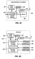
- a MIMO communication system 10 is illustrated in block diagram form as generally including a single transmitter 12 having multiple transmission antennas (or antenna elements) 14A-14N and a single receiver 16 having multiple receiver antennas (or antenna elements) 18A-18M.
- the number of transmission antennas 14A-14N can be the same as, more than, or less than the number of receiver antennas 18A-18M.
- the transmitter 12 may include a controller 20 coupled to a memory 21, to a symbol encoder and modulator unit 22 and to a spatial spreading block 24.
- the transmitter 12 may also include a matrix equalizer 25 and a symbol demodulator and decoder unit 26 to perform demodulation and decoding of signals received via the antennas 14A-14N in a receive mode. Additionally, in some instances, the transmitter 12 may include a spreading matrix calculation unit 28.
- the controller 12 may be any desired type of controller and the controller 12 and the spreading matrix calculation unit 28 may be implemented as one or more standard multi-purpose, programmable processors, such as micro-processors, as application specific integrated circuits (ASICs), etc., or may be implemented using any other desired types of hardware, software and/or firmware.
- the spatial spreading block 24, and the matrix equalizer 25 may be implemented using known or standard hardware and/or software elements. If desired, various of the transmitter components, such as the controller 20, the modulator unit 22, the demodulator unit 26, the spreading matrix calculation unit 28, the spatial spreading block 24 and the matrix equalizer 25 may be implemented in the same or in different hardware devices, such as in the same or different processors.
- each of these components of the transmitter 12 may be disposed in a housing 31 (shown in dotted relief in Fig. 1 ) and the routines or instructions for implementing the functionality of any of these components may be stored in the memory 21 or within other memory devices associated with the individual hardware used to implement these components.
- one or more pre-calculated or predetermined spatial spreading matrices may be stored in the memory 21 and used in the spatial spreading matrix block 24 at various times or under various different conditions.
- a different pre-calculated or predetermined spatial spreading matrix may be stored for each of a number of possible combinations of encoded spatial streams of data to be transmitted and transmission antennas 14 to be used to simultaneously transmit these encoded spatial streams of data.
- a different spatial spreading matrix may be calculated and stored for two spatial streams of data being sent via three of the transmission antennas 14, for two spatial streams of data being sent via four of the transmission antennas 14, for three spatial streams of data being sent via five transmission antennas 14, etc.
- the communication system 10 may optimally send different numbers of spatial streams of data at different times, depending on the load of the system. Moreover, the communication system 10 may also use these various different pre-stored or pre-calculated spatial spreading matrices to account for or to adapt to the loss of one or more of the transmission antennas 14 to be used in sending data within the communication system 10.
- information signals T x1 - T xn which are to be transmitted from the transmitter 12 to the receiver 16 are provided to the symbol encoder and modulator unit 22 for encoding and modulation.
- any desired number of signals T x1 - T xn may be provided to the modulator unit 22, with this number generally being limited by the modulation scheme used by and the bandwidth associated with the MIMO communication system 10.
- the signals T x1 - T xn may be any type of signals, including analog or digital signals, and may represent any desired type of data or information.
- a known test or control signal C x1 (which may be stored in the memory 21) may be provided to the symbol encoder and modulator unit 22 for use in determining CSI related information describing the characteristics of the channel(s) between the transmitter 12 and the receiver 16. If desired, the same control signal or a different control signal may be used to determine the CSI for each frequency and/or spatial channel used in the MIMO, communication system 10.
- the symbol encoder and modulator unit 22 may interleave digital representations of the various signals T x1 - T xn and C x1 and may perform any other known type(s) of error-correction encoding on the signals T x1 - T xn and C x1 to produce one or more encoded streams of symbols SS 1 , SS 2 , ... SS p , to be modulated and sent from the transmitter 12 to the receiver 16. While the symbol streams SS 1 - SS p may be modulated using any desired or suitable QAM technique, such as using 64 QAM, these symbols may be modulated in any other known or desired manner including, for example, using any other desired phase and/or frequency modulation techniques.
- the modulated encoded symbol streams SS 1 - SS p are provided by the symbol encoder and modulator unit 22 to the spatial spreading block 24 for processing before being transmitted via the antennas 14A-14N. While not specifically shown in Fig. 1 , the modulated symbol streams SS 1 - SS p may be processed by the spatial spreading block 24 that implements a spatial spreading matrix in accordance with a transmission technique more specifically described below, before being up-converted to the RF carrier frequencies associated with an OFDM technique (in one or more stages).
- the spatial spreading block 24 Upon receiving the modulated signals, the spatial spreading block 24 processes the modulated signals by injecting delays and/or gains into the modulated signals based on a spatial spreading matrix which may be calculated by the spreading matrix calculation unit 28, and provided by, for example, the controller 12, to thereby perform mixing and transmission of the spatial streams of data across the transmission antennas 14A-14N and across the transmission chains.
- a spatial spreading matrix which may be calculated by the spreading matrix calculation unit 28, and provided by, for example, the controller 12, to thereby perform mixing and transmission of the spatial streams of data across the transmission antennas 14A-14N and across the transmission chains.
- the signals transmitted by the transmitter 12 are received by the receiver antennas 18A-18M and may be processed by a matrix equalizer 35 within the receiver 16 to enhance the reception capabilities of the antennas 18A-18M.
- the processing applied at the receiver 16 may be based on, for example, the CSI developed by the receiver 16 in response to the transmission of the test or control signal C x1 .
- a controller 40 or other unit within the receiver 16 such as a channel determination unit 39, may process the received control signal C x1 and develop therefrom a measured description of the forward channel between the transmitter 12 and the receiver 16 by determining or characterizing the propagation effects of the forward channel on the signal C x1 as it traveled through the forward channel.
- a symbol demodulator and decoder unit 36 under control of the controller 40, may decode and demodulate the received symbol strings SS 1 - SS p as recovered by the matrix equalizer 35. In this process, these signals may be downconverted to baseband.
- the demodulator and decoder unit 36 may operate to remove effects of the forward channel based on the CSI as well as to perform demodulation on the received symbols in each symbol stream SS 1 - SS p to produce a digital bit stream for each stream.
- the symbol demodulator and decoder unit 36 may perform error correction decoding and deinterleaving on the bit stream to produce the received signals R x1 -R xn corresponding to the originally transmitted signals T x1 -T xn .
- the receiver 16 may also include a memory 41 and a symbol encoder and modulator unit 46 which may receive one or more signals T R1 -T Rm encoded and modulated using any desired encoding and modulation techniques.
- the receiver 16 may also provide one or more known test or control signals C R1 to the symbol encoder/modulator unit 46 to be sent to the transmitter 12 to enable the transmitter 12 to determine a measured description of the reverse channel between the receiver 16 and the transmitter 12.
- the encoded and modulated symbol stream may then be upconverted and processed by a spatial spreading block 34 which may use a spatial spreading matrix developed according to the principles described herein based on the number of symbol streams to be sent simultaneously, the number of receiver and/or transmitter chains to be used, and the number of transmission antennas 18 to be used.
- the output of the spatial spreading block 34 is then transmitted via the receiver antennas 18A-18N to, for example, the transmitter 12, thereby implementing the reverse link.
- the receiver 16 is able to compute not only receiving antenna selection (Rx ASEL), but also transmission antenna selection (Tx ASEL) or joint transmission/receiving antenna selection (TX/Rx ASEL).
- the receiver 16 may either feed back the channel state information or compute antenna selection and feed back the selected antenna information in a subsequent transmit opportunity.
- each of the receiver components may be disposed in a housing 51.
- the matrix equalizer 25 and the demodulator/decoder unit 26 within the transmitter 12 operate similarly to the matrix equalizer 35 and the demodulator/decoder unit 36 of the receiver 16 to demodulate and decode the symbol streams transmitted by the receiver 16 to produce the recovered signals R R1 -R Rm .
- the matrix equalizer 25 may process the received signals in any known manner to enhance the separation and therefore the reception of the various symbol streams transmitted by the antennas 18A-18M.
- the CSI or other measured description of the forward channel for the various OFDM channel(s) may be used to process or decode the received signals.
- the spatial spreading matrix when selecting antennas for transmitting and/or receiving the data transmissions.
- the data is transmitted along one or more receive chains at the receiver, N R , and one or more transmitting chains at the transmitter, N T .
- this could be a channel on one subcarrier of the system.
- the data streams in the chain-to-chain transmission go through a channel matrix, H.
- the channel matrix, H is defined as the full MIMO channel between the transmission antennas 14A-14N and the receiving channels 18A-18M (i.e., a full-dimensional channel matrix) which describes the full-dimensions of the channel between the stations 12, 16.
- the channel matrix, H has a row dimension corresponding to the number of receiving antennas, M R , and a column dimension corresponding to the number of transmission antennas, M T , thereby creating an M R x M T matrix.
- the channel matrix, H it should be understood that the transmitter 12 and receiver 16 may actually use an estimate of the channel matrix, H, based on, for example, sounding information and/or the CSI. Accordingly, as used herein, it should be understood that the channel matrix, H, as used by the transmitter 12 and receiver 16 may be an estimate of the channel matrix, H, as sometimes referred to herein.
- the actual matrix channel is a sub-matrix, H s , of the full-dimensional channel matrix, H. Because the channel coefficients corresponding to the different antennas are different, it is important to select the appropriate antennas to transmit and/or receive the transmission. As indicated above, when the number of antennas are larger than the number of chains, the antenna selection is artificial when appropriate antenna selection is not used. Selection of appropriate or most optimal antenna subsets of the available antennas allows for the selection of a subset of available antennas matched to the number of chains, thereby achieving high channel gain.
- Antenna selection is conducted based on an estimation of the sub-matrix H s .
- the transmitter 12 (Station A) determines an estimation of H S based on an estimate of the channel from the receiver 16 (Station B) to Station A, or vice versa.
- transmission antenna selection (TX ASEL) is conducted if the number of transmission antennas, M T , is.greater than the number of transmit chains, N T , and the number of receiving antennas, M R , is equal to the number of receiving chains, N R .
- receiving antenna selection is conducted if the number of receiving antennas, M R , is greater than the number of receiving chains, N R , and the number of transmission antennas, M T , is equal to the number of transmit chains, N T .
- TX ASEL transmitting and receiving antenna selection
- the antenna selection computation may be directly conducted at the transmitter 12 or the receiver 16
- RX ASEL the antenna selection computation is conducted at the receiver 16.
- the antenna selection may be conducted as the receiver 16.
- antenna selection may be conducted by selecting the optimal columns and rows from the full-dimensional channel matrix, H. As is known, this may be done based on certain optical criterion, such as channel capacity, substream signal-to-noise ratio, etc.
- the optimal columns and rows may be selected by conducting antenna selection training, where channel sounding information is send over different antenna subsets using antenna switching.
- channel sounding information is sent over different subsets of the transmission antennas 14A-14N, where the switch (not shown) switches between the subsets of transmission antennas 14A-14N.
- the sounding information is received over different subsets of the receiving antennas 18A-18M, where the switch (not shown) switches between the subsets of the receiving antennas 18A-18M.
- the full-dimensional channel matrix, H is equal to the set [H1 H2], where H1 and H2 are the sub-channels with a number of transmission antennas equal to the number of transmit chains, N T (e.g., H1 is the channel from the first N T transmission antennas, and H2 is the channel from the second N T transmission antennas).
- N T e.g., H1 is the channel from the first N T transmission antennas, and H2 is the channel from the second N T transmission antennas.
- a spatial spreading (or mapping) matrix, Q is applied.
- the spatial spreading matrix, Q is the full-dimensional channel spatial spreading matrix having a row component equal to the number of transmit chains, N T , and a column component also equal to the number of transmit chains, N T , thereby forming an N T x N T matrix.
- An example of the full-dimensional spatial spreading matrix, Q is defined in the IEEE 802.11n standard.
- Station B removes Q and is able to derive H.
- the full-dimensional channel spatial spreading matrix Q is an orthogonal matrix
- the full-dimensional spatial spreading matrix, Q is known by the transmitter 12 (Station A) when conducting antenna selection, because the transmitter applies the full-dimensional spatial spreading matrix, Q, to the transmission in order to map the encoded spatial data streams to the transmit chains.
- Q also needs to be known by the receiver 16 (Station B) in order to estimate the sub-matrix channel, H s , Q is predefined, so that the receiver 16 may remove the full-dimensional spatial spreading matrix, Q, and derive an estimate of the full-dimensional channel matrix, H, and, in turn, derive the sub-matrix channel, H s , based on previous antenna selection training. That is, Station B is able to determine an estimation of H S based on an estimate of the full-dimensional channel matrix, H, from Station A to Station B.
- the number of spatial data streams, N ss may be less than the number of transmit chains, N T , because it is desirable to transmit all signals from all available transmit chains in order to maximize the channel gain.
- the spatial mapping of the spatial data streams to the transmit chains is performed by applying a spatial spreading matrix, Q d , before transmitting the data and after antenna selection, rather than applying the full-dimensional spatial spreading matrix, Q.
- the spatial spreading matrix, Q d has a row dimension corresponding to the number of transmit chains, N T , and a column dimension corresponding to the number of spatial data streams, N ss , thereby creating an N T x N SS matrix.
- antenna selection during training is based on the full-dimensional spatial spreading matrix, Q
- the actual operation of transmitting the spatial data streams is based on the spatial spreading matrix, Q d .
- Q d may be any arbitrary matrix designed by, and therefore known to, the transmitter 12, Q d is unknown to the receiver 16, which bases its antenna selection on the full-dimensional spatial spreading matrix, Q.
- the previously performed antenna selection computation is not accurate.
- Q d is not an identity matrix, because in the above case some of the N T - N ss transmit chains will be switched off and the transmission power level will be reduced. That is, the N T transmit chains are connected by the previously selected transmission antennas. If Q d is an identify matrix, then Q d does not need to be known and is essentially equal to nothing. Further, Q d is applicable when the number of spatial data streams, N ss is less than the minimum of the transmit chains, N T , and the receiving chains, N R (i.e., N SS ⁇ min(N T , N R )).
- the spatial mapping matrix, Q d used to map the spatial data streams to the transmit chains is used for antenna selection training at the transmitter 12 and/or receiver 16. That is, antenna selection computation accounts for Q d .
- Q d is predefined and known by the receiver 16. In one example described further below, Q d may be predefined as part of the wireless protocol utilized by the transmitter 12 and receiver 16, such as the 802.11n standard or subsequent 802.11(x) standards.
- the station (Station A or B) conducting the antenna selection computation knows that Q d will be applied at the transmitter 12, in which case the station also knows the number of spatial data streams, N ss .
- N T the minimum of the transmit chains
- N R the receiving chains
- antenna selection may be conducted using conventional techniques.
- the antenna selection example described below is based on the situation where the number of spatial data streams is less than the minimum of the transmit chains, N T , and the receiving chains, N R , in which case the antenna selection accounts for the spatial spreading matrix, Q d .
- the station conducting the antenna selection searches over all different combinations of sub-matrices, H s , of size N R x N T within the full-dimensional channel matrix, H.
- H s Each different combination of H S is denoted as H1, H2, ..., Hk, where k is the number of all possible sub-matrices of size N R x N T within the full-dimensional channel matrix, H.
- each of the sub-matrices may be right-multiplied by the spatial spreading matrix, Q d , to form channel estimation sub-matrices corresponding to each of the sub-matrices H1-Hk.
- the spatial spreading matrix, Q d is the first set of columns in the full-dimensional spatial spreading matrix, Q, corresponding to the number of spatial data streams, N SS , (i.e., the first N SS columns of Q)
- right-multiplying with Q d is not needed in order to determine the full-dimensional channel matrix, H, and antenna selection computation may be conducted directly.
- a set of optimality criterion e.g., channel capacity, substream signal-to-noise ratio, etc.
- selecting one of the channel estimation sub-matrices, H1'-Hk' may include developing a steering matrix for each channel estimation sub-matrix and applying each steering matrix to the corresponding channel estimation sub-matrix. Once the steering matrix has been applied, the spatial spreading matrix, Q d , is applied to each channel estimation sub-matrix.
- the transmitter should apply advanced schemes, such as beamforming and steering matrix application, before applying the spatial spreading matrix, Q d , to each channel estimation sub-matrix. This is because the nature of such schemes tend to change the spatial mapping, and when the transmitter changes the spatial mapping (i.e., changes Qd), antenna selection performance gain may suffer due to the previous antenna selection results no longer being accurate or applicable to the new Q d .
- the test signals are transmitted from Station A to Station B using the test steering matrices and the spatial spreading matrix. From these transmissions, a quality factor may be determined for each of the test signals and returned back from the receiver 16 to the transmitter 12. Using the quality factors, the optimal channel estimation sub-matrix may be selected, and the antennas corresponding to the selected channel estimation sub-matrix may be selected.
- the above antenna selection computation As a result of the above antenna selection computation, all possible sub-matrices within the full-dimensional channel matrix, H, are trained. This means that all possible combinations of antennas are trained using the spatial spreading matrix, Q d . As will be understood, there may be different ways to account for Q d during antenna selection computation, of which the above is only an example. As will also be understood, the above antenna selection computation may be applied to transmission antenna selection at the transmitter 12, transmission antenna selection at the receiver 16, receiver antenna selection as the receiver 16 and joint transmission/receiving antenna selection at either the transmitter 12 or receiver 16.
- antenna selection computation may always be conducted at the transmitter 12 with the spatial spreading matrix, Q d , known, given that the transmitter 12 applies the spatial spreading matrix to map the spatial data streams to the transmit chains.
- the spatial spreading matrix, Q d along with the full-dimensional spatial spreading matrix, Q, should be pre-defined, preferably in the communication standard being used between the transmitter 12 and receiver 16 (e.g., IEEE 802.1 In). If the spatial spreading matrix, Q d , is predefined for the receiver 16, the receiver 16 is able to conduct antenna selection computation based on the full-dimensional channel matrix, H, and based on Q d .
- the receiver 16 should compute the antenna selection based on the assumption that the first N SS columns in the full-dimensional spatial spreading matrix, Q, will be applied at the transmitter 12 for data transmission after antenna selection switching.
- An additional factor in achieving the best performance has the transmitter 12 applying the first N ss column in the full-dimensional spatial spreading matrix, Q for spatial mapping (i.e., Q d ) for data transmission after antenna selection switching.
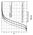
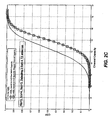
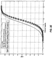
- Some example antenna selection computations and the results thereof using spatial spreading matrices derived from the above-described techniques are provided below for a 4x2 chain system used to simultaneously send one spatial stream (four receive chains and two transmit chains in a 4x4 antenna system), a 4x3 chain system used to simultaneously send two spatial streams (four receive chains and three transmit chains in a 4x4 antenna system), a 4x3 chain system used to simultaneously send three spatial streams (four receive chains and three transmit chains in a 4x4 antenna system), 2x2 chain system used to simultaneously send one spatial stream (two receive chains and two transmit chains in a 4x2 antenna system), and a 3x3 chain system used to simultaneously send two spatial streams (three receive chains and three transmit chains in a 4x3 antenna system), all with a signal-to-noise ratio of 20dB, a Rayleigh fading channel and 10000 simulated samples.
- the channel strengths or channel capacity (as indicated) of the equivalent channel estimation matrix are plotted with respect to the cumulative density function (CDF) of the post-processing channel gain at the receiver corresponding to different antenna selection strategies.
- CDF cumulative density function
- Channel capacity is plotted in some instances, because channel capacity is a better indicator of quality than channel strength.
- the CDF curves on the right of the plots shown in Figs. 2A-2E imply a higher possible realization of the random variable (i.e., higher post-processing channel gain).
- the full-dimensional spatial spreading matrix, Q is orthogonal for purposes of the examples only.
- an orthogonal matrix is easy to remove by multiplying the transpose conjugate of the matrix to obtain the identity matrix, rather than performing matrix inversion, though it should be understood that the full-dimensional spatial spreading matrix, Q, need not be orthogonal in all instances.
- no antenna selection denoted by the straight line plot
- antenna selection based on the full-dimensional spatial spreading matrix, Q, and the full-dimensional channel matrix, H denoted by the circle line plot
- the most optimal antenna selection based on the spatial spreading matrix, Q d , and the channel sub-matrix, H s denoted by the square line plot, results in the best gain.
- antenna selection based on the full-dimensional spatial spreading matrix, Q, and full-dimensional channel matrix, H has a limited gain as compared to no antenna selection, and the most optimal antenna selection based on the spatial spreading matrix, Q d , and the channel sub-matrix, H s , results in the best gain.
- antenna selection based on the full-dimensional spatial spreading matrix, Q, and full-dimensional channel matrix, H has a limited gain
- the most optimal antenna selection based on the spatial spreading matrix, Q d , and the channel sub-matrix, H s results in the best gain.
- the manner in which the spatial spreading matrix, Q d , is calculated or determined is not particularly important.
- any mathematical, heuristic, iterative, or trial and error method can be used to actually determine or compute any particular size of spatial spreading matrix, and the method used to compute a spatial spreading matrix is not determinative.
- the specific orientation or definition of the "row” and "column" dimensions of a matrix as used herein is arbitrary and is simply based on convention, and therefore may be changed.
- the row dimension can be a horizontal dimension with the column dimension being a vertical dimension (as assumed herein), or the row dimension can be a vertical dimension with the column dimension being a horizontal dimension.
- the actual spatial spreading matrix equations may be performed at any desired location within the wireless communication system 10 of Fig. 1 , including within the controller 20 or other hardware, software, or firmware of the transmitter 12, as well as within the controller 40 or other hardware, software, or firmware of the receiver 16.
- the spatial spreading matrix may be pre-computed and stored in the memory 21 (or 41) or other memory of the system 10 prior to the transmission system being used.
- the spatial spreading matrix or matrices may also be computed or determine by a different device and may be sent to the transmitter 12 or the receiver 14 of the transmission system 10 at any desired time.
- the spatial spreading matrix technique described herein is not limited to being used in a transmitter of a MIMO communication system communicating with a single receiver of the MIMO communication system, but can additionally be applied when a transmitter of a MIMO communication system is communicating with multiple receivers, each of which has one or more receiver antennas associated therewith.
- routines may alternatively or additionally be implemented in digital or analog hardware, firmware, application specific integrated circuits, etc., as desired. If implemented in software, the routines may be stored in any computer readable memory such as in RAM, ROM, flash memory, a magnetic disk, a laser disk, or other storage medium.
- this software may be delivered to a MIMO system device (such as a transmitter or a receiver) via any known or desired delivery method including, for example, over a communication channel such as a telephone line, the Internet, a wireless connection, etc., or via a transportable medium, such as a computer-readable disk, flash drive, etc.
- a communication channel such as a telephone line, the Internet, a wireless connection, etc.
- a transportable medium such as a computer-readable disk, flash drive, etc.
- the above antenna selection and training techniques may be embodied in any type of wireless communication system including, for example, ones used in wireless computer systems such as those implemented via a local area network or a wide area network, internet, cable and satellite based communication systems (such as internet, data, video and voice communication systems), wireless telephone systems (including cellular phone systems, voice over internet protocol (VoIP) systems, home-based wireless telephone systems, etc.)
- wireless computer systems such as those implemented via a local area network or a wide area network
- internet, cable and satellite based communication systems such as internet, data, video and voice communication systems
- wireless telephone systems including cellular phone systems, voice over internet protocol (VoIP) systems, home-based wireless telephone systems, etc.
- the antenna selection and training techniques may be used with a hard disk drive 400 which includes both signal processing and/or control circuits, which are generally identified in Fig. 3A at 402.
- signal processing and/or control circuit 402 and/or other circuits (not shown) in HDD 400 may process data, perform coding and/or encryption, perform calculations, and/or format data that is output to and/or received from a magnetic storage medium 406.
- HDD 400 may communicate with a host device (not shown) such as a computer, mobile computing devices such as personal digital assistants, cellular phones, media or MP3 players and the like, and/or other devices via one or more wired or wireless communication links 408 which may implement the antenna selection and training techniques described above.
- HDD 400 may be connected to memory 409, such as a random access memory (RAM), a low latency nonvolatile memory such as flash memory, read only memory (ROM) and/or other suitable electronic data storage.
- RAM random access memory
- ROM read only memory
- the antenna selection and training techniques may be embodied in or used with a digital versatile disc (DVD) drive 410 which may include either or both signal processing and/or control circuits, which are generally identified in Fig. 3B at 412, and/or mass data storage 418 of DVD drive 410.
- Signal processing and/or control circuit 412 and/or other circuits (not shown) in DVD 410 may process data, perform coding and/or encryption, perform calculations, and/or format data that is read from and/or data written to an optical storage medium 416.
- signal processing and/or control circuit 412 and/or other circuits (not shown) in DVD 410 can also perform other functions such as encoding and/or decoding and/or any other signal processing functions associated with a DVD drive.
- DVD drive 410 may communicate with an output device (not shown) such as a computer, television or other device via one or more wired or wireless communication links 417 which may be implemented using the antenna selection and training techniques described above.
- DVD 410 may communicate with mass data storage 418 that stores data in a nonvolatile manner.
- Mass data storage 418 may include a hard disk drive (HDD) such as that shown in Fig. 3A .
- the HDD may be a mini HDD that includes one or more platters having a diameter that is smaller than approximately 1.8".
- DVD 410 may be connected to memory 419, such as RAM, ROM, low latency nonvolatile memory such as flash memory, and/or other suitable electronic data storage.
- the antenna selection and training techniques may be embodied in a high definition television (HDTV) 420 which may include either or both signal processing and/or control circuits, which are generally identified in Fig. 3C at 422, a WLAN interface and/or mass data storage of the HDTV 420.
- HDTV 420 receives HDTV input signals in either a wired or wireless format and generates HDTV output signals for a display 426.
- signal processing circuit and/or control circuit 422 and/or other circuits (not shown) of HDTV 420 may process data, perform coding and/or encryption, perform calculations, format data and/or perform any other type of HDTV processing that may be required.
- HDTV 420 may communicate with mass data storage 427 that stores data in a nonvolatile manner such as optical and/or magnetic storage devices. At least one HDD may have the configuration shown in Fig. 3A and/or at least one DVD may have the configuration shown in Fig. 3B .
- the HDD may be a mini HDD that includes one or more platters having a diameter that is smaller than approximately 1.8".
- HDTV 420 may be connected to memory 428 such as RAM, ROM, low latency nonvolatile memory such as flash memory and/or other suitable electronic data storage.
- HDTV 420 also may support connections with a WLAN via a WLAN network interface 429 which may implement the beamforming techniques described above.
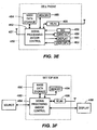
- the antenna selection and training techniques may be used in conjunction with a control system of a vehicle 430 having a WLAN interface and/or mass data storage.
- the antenna selection and training techniques may be used within a powertrain control system 432 that receives inputs from one or more sensors such as temperature sensors, pressure sensors, rotational sensors, airflow sensors and/or any other suitable sensors and/or that generates one or more output control signals such as engine operating parameters, transmission operating parameters, and/or other control signals.
- control system 440 may likewise receive signals from input sensors 442 and/or output control signals to one or more output devices 444.
- control system 440 may be part of an anti-lock braking system (ABS), a navigation system, a telematics system, a vehicle telematics system, a lane departure system, an adaptive cruise control system, a vehicle entertainment system such as a stereo, DVD, compact disc and the like. Still other implementations are contemplated.
- ABS anti-lock braking system
- Powertrain control system 432 may communicate with mass data storage 446 that stores data in a nonvolatile manner.
- Mass data storage 446 may include optical and/or magnetic storage devices for example hard disk drives HDD and/or DVDs. At least one HDD may have the configuration shown in Fig. 3A and/or at least one DVD may have the configuration shown in Fig. 3B .
- the HDD may be a mini HDD that includes one or more platters having a diameter that is smaller than approximately 1.8".
- Powertrain control system 432 may be connected to memory 447 such as RAM, ROM, low latency nonvolatile memory such as flash memory and/or other suitable electronic data storage.
- Powertrain control system 432 also may support connections with a WLAN via a WLAN network interface 448 which may implement the antenna selection and training techniques described above.
- the control system 440 may also include mass data storage, memory and/or a WLAN interface (all not shown).
- the antenna selection and training techniques may be embodied in a cellular phone 450 that may include one or more cellular antennas 451, either or both signal processing and/or control circuits, which are generally identified in Fig. 3E at 452, a WLAN interface and/or mass data storage of the cellular phone 450.
- cellular phone 450 includes a microphone 456, an audio output 458 such as a speaker and/or audio output jack, a display 460 and/or an input device 462 such as a keypad, pointing device, voice actuation and/or other input device.
- Signal processing and/or control circuits 452 and/or other circuits (not shown) in cellular phone 450 may process data, perform coding and/or encryption, perform calculations, format data and/or perform other cellular phone functions.
- Cellular phone 450 may communicate with mass data storage 464 that stores data in a nonvolatile manner such as optical and/or magnetic storage devices for example hard disk drives HDD and/or DVDs. At least one HDD may have the configuration shown in Fig. 3A and/or at least one DVD may have the configuration shown in Fig. 3B . The HDD may be a mini HDD that includes one or more platters having a diameter that is smaller than approximately 1.8".
- Cellular phone 450 may be connected to memory 466 such as RAM, ROM, low latency nonvolatile memory such as flash memory and/or other suitable electronic data storage. Cellular phone 450 also may support connections with a WLAN via a WLAN network interface 468.
- the antenna selection and training techniques may be embodied in a set top box 480 including either or both signal processing and/or control circuits, which are generally identified in Fig. 3F at 484, a WLAN interface and/or mass data storage of the set top box 480.
- Set top box 480 receives signals from a source such as a broadband source and outputs standard and/or high definition audio/video signals suitable for a display 488 such as a television and/or monitor and/or other video and/or audio output devices.
- Signal processing and/or control circuits 484 and/or other circuits (not shown) of the set top box 480 may process data, perform coding and/or encryption, perform calculations, format data and/or perform any other set top box function.
- Set top box 480 may communicate with mass data storage 490 that stores data in a nonvolatile manner.
- Mass data storage 490 may include optical and/or magnetic storage devices for example hard disk drives HDD and/or DVDs. At least one HDD may have the configuration shown in Fig. 3A and/or at least one DVD may have the configuration shown in Fig. 3B .
- the HDD may be a mini HDD that includes one or more platters having a diameter that is smaller than approximately 1.8".
- Set top box 480 may be connected to memory 494 such as RAM, ROM, low latency nonvolatile memory such as flash memory and/or other suitable electronic data storage.
- Set top box 480 also may support connections with a WLAN via a WLAN network interface 496 which may implement the antenna selection and training techniques described herein.
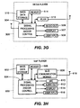
- the antenna selection and training techniques may be embodied in a media player 500.
- the antenna selection and training techniques may implement either or both signal processing and/or control circuits, which are generally identified in Fig. 3G at 504, a WLAN interface and/or mass data storage of the media player 500.
- media player 500 includes a display 507 and/or a user input 508 such as a keypad, touchpad and the like.
- media player 500 may employ a graphical user interface (GUI) that typically employs menus, drop down menus, icons and/or a point-and-click interface via display 507 and/or user input 508.
- Media player 500 further includes an audio output 509 such as a speaker and/or audio output jack.
- Signal processing and/or control circuits 504 and/or other circuits (not shown) of media player 500 may process data, perform coding and/or encryption, perform calculations, format data and/or perform any other media player function.
- Media player 500 may communicate with mass data storage 510 that stores data such as compressed audio and/or video content in a nonvolatile manner.
- the compressed audio files include files that are compliant with MP3 format or other suitable compressed audio and/or video formats.
- the mass data storage may include optical and/or magnetic storage devices for example hard disk drives HDD and/or DVDs. At least one HDD may have the configuration shown in Fig. 3A and/or at least one DVD may have the configuration shown in Fig. 3B .
- the HDD may be a mini HDD that includes one or more platters having a diameter that is smaller than approximately 1.8".
- Media player 500 may be connected to memory 514 such as RAM, ROM, low latency nonvolatile memory such as flash memory and/or other suitable electronic data storage.
- Media player 500 also may support connections with a WLAN via a WLAN network interface 516 which may implement the antenna selection and training techniques described herein. Still other implementations in addition to those described above are contemplated.
- VoIP phone 600 may include one or more antennas 618, either or both signal processing and/or control circuits, which are generally identified in Fig. 3H at 604, and a wireless interface and/or mass data storage of the VoIP phone 600.
- VoIP phone 600 includes, in part, a microphone 610, an audio output 612 such as a speaker and/or audio output jack, a display monitor 614, an input device 616 such as a keypad, pointing device, voice actuation and/or other input devices, and a Wireless Fidelity (Wi-Fi) communication module 608.
- Signal processing and/or control circuits 604 and/or other circuits (not shown) in VoIP phone 600 may process data, perform coding and/or encryption, perform calculations, format data and/or perform other VoIP phone functions.
- VoIP phone 600 may communicate with mass data storage 602 that stores data in a nonvolatile manner such as optical and/or magnetic storage devices, for example hard disk drives HDD and/or DVDs. At least one HDD may have the configuration shown in Fig. 3A and/or at least one DVD may have the configuration shown in Fig. 3B .
- the HDD may be a mini HDD that includes one or more platters having a diameter that is smaller than approximately 1.8".
- VoIP phone 600 may be connected to memory 606, which may be a RAM, ROM, low latency nonvolatile memory such as flash memory and/or other suitable electronic data storage.
- VoIP phone 600 is configured to establish communications link with a VoIP network (not shown) via Wi-Fi communication module 608 which may implement the antenna selection and training techniques described herein.
Landscapes
- Engineering & Computer Science (AREA)
- Computer Networks & Wireless Communication (AREA)
- Signal Processing (AREA)
- Physics & Mathematics (AREA)
- Mathematical Physics (AREA)
- Radio Transmission System (AREA)
- Mobile Radio Communication Systems (AREA)
Claims (15)
- Procédé de sélection d'antenne dans un système de communication comportant un premier dispositif émetteur-récepteur ayant une pluralité d'antennes d'émission (14A à 14N) et un second dispositif émetteur-récepteur ayant une pluralité d'antennes de réception (18A à 18M), le procédé comprenant :le codage de données de transmission pour produire un ou plusieurs trains de données spatiales codés pour transmission par l'intermédiaire d'un certain nombre de chaînes de transmission, dans lequel le nombre de trains de données spatiales codés est différent du nombre de chaînes de transmission à utiliser pour transmettre les trains de données spatiales codés et dans lequel le nombre de chaînes de transmission est inférieur au nombre d'antennes d'émission (14A à 14N) ;l'utilisation d'une matrice d'étalement spatial pour distribuer les trains de données spatiales codées au nombre de chaînes de transmission, dans lequel la matrice d'étalement spatial possède des composants associés avec la dimension de rangée ayant un nombre de rangées égal au nombre de chaînes de transmission à utiliser pour transmettre les trains de données spatiales codés et une dimension de colonne ayant un nombre de colonnes égal au nombre de trains de données spatiales codés à transmettre ; etla sélection d'une ou plusieurs antennes de la pluralité d'antennes d'émission (14A à 14N) à utiliser pour transmettre des données à une ou plusieurs de la pluralité d'antennes de réception (18A à 18M) en se basant sur une matrice d'estimation de canal qui estime un canal à entrées multiples, sorties multiples, MIMO, entre le premier dispositif émetteur-récepteur et le second dispositif émetteur-récepteur, dans lequel la matrice d'estimation de canal possède des composants associés avec une dimension de rangée ayant un nombre de rangées égal au nombre de chaînes de réception et une dimension de colonne ayant un nombre de colonnes égal au nombre de trains de données spatiales codés à transmettre, etdans lequel la sélection de la ou des antennes de la pluralité d'antennes d'émission (14A à 14N) comprend la prise en compte de la matrice d'étalement spatial.
- Procédé selon la revendication 1, dans lequel
la sélection de la ou des antennes de la pluralité d'antennes d'émission (14A à 14N) comprend la suppression d'une matrice d'étalement spatial Q de la matrice d'estimation de canal pour déterminer une matrice d'estimation de canal chaîne à chaîne, et
la sélection de la ou les antennes de la pluralité d'antennes d'émission (14A à 14N) est fondée sur la matrice de canal chaîne à chaîne et prend en compte une matrice d'étalement spatial Qd. - Procédé selon la revendication 1, dans lequel la sélection de la ou des antennes de la pluralité d'antennes d'émission (14A à 14N) à utiliser pour transmettre des données à une ou plusieurs antennes de la pluralité d'antennes de réception par l'intermédiaire d'une matrice de canal entre le premier dispositif émetteur-récepteur et le second dispositif émetteur-récepteur comprend :la recherche de sous-matrices de canal potentielles dans une matrice de canal pleine dimension correspondant à une description pleine dimension du canal entre la pluralité d'antennes d'émission et la pluralité d'antennes de réception, dans lequel la matrice de canal pleine dimension possède des composants associés avec une dimension de rangée ayant un nombre de rangées égal au nombre d'antennes de réception et une dimension de colonne ayant un nombre de colonnes égal au nombre d'antennes d'émission, et dans lequel chaque sous-matrice de canal possède des composants associés avec une dimension de rangée ayant un nombre de rangées égal au nombre de chaînes de réception et une dimension de colonne ayant un nombre de colonnes égal au nombre de chaînes de transmission ;la sélection d'une des sous-matrices de canal en se fondant sur un critère d'optimalité, dans lequel la matrice d'estimation de canal utilisée pour transmettre les données à une ou plusieurs antennes de la pluralité d'antennes de réception comprend la sous-matrice de canal sélectionnée ; etla sélection d'un sous-ensemble de la pluralité d'antennes d'émission correspondant à la matrice de canal sélectionnée.
- Procédé selon la revendication 3, comprenant en outre la multiplication droite de chaque sous-matrice de canal potentielle avec la matrice d'étalement spatial pour former une sous-matrice d'estimation de canal correspondante ayant des composants associés avec une dimension de rangée ayant un nombre de rangées égal au nombre de chaînes de réception et une dimension de colonne ayant un nombre de colonnes égal au nombre de trains de données spatiales codés à transmettre.
- Procédé selon la revendication 3, dans lequel la recherche des sous-matrices de canal potentielles dans une matrice de canal pleine dimension comprend la recherche de toutes les sous-matrices de canal potentielles dans la matrice de canal pleine dimension et dans lequel la matrice d'étalement spatial comprend un certain nombre de premières colonnes dans une matrice d'étalement spatial de canal pleine dimension, dans lequel la matrice d'étalement spatial de canal pleine dimension possède des composants associés avec une dimension de rangée ayant un nombre de rangées égal au nombre de chaînes de transmission à utiliser pour transmettre les trains de données spatiales codés et une dimension de colonne ayant un nombre de colonnes égal au nombre de chaînes de transmission à utiliser pour transmettre les trains de données spatiales codés, dans lequel le nombre de premières colonnes dans la matrice d'étalement spatial de canal pleine dimension est égal au nombre de trains de données spatiales codés à transmettre.
- Procédé selon la revendication 1, dans lequel le nombre de trains de données spatiales codés est inférieur au minimum du nombre de chaînes de transmission et du nombre de chaînes de réception.
- Procédé selon la revendication 1, dans lequel la matrice d'étalement spatial comprend un certain nombre de premières colonnes dans une matrice d'étalement spatial de canal pleine dimension, dans lequel la matrice d'étalement spatial de canal pleine dimension possède des composants associés avec une dimension de rangée ayant un nombre de rangées égal au nombre de chaînes de transmission à utiliser pour transmettre les trains de données spatiales codés et une dimension de colonne ayant un nombre de colonnes égal au nombre de chaînes de transmission à utiliser pour transmettre les trains de données spatiales codés, dans lequel le nombre de premières colonnes dans la matrice d'étalement spatial de canal pleine dimension est égal au nombre de trains de données spatiales codés à transmettre.
- Procédé selon la revendication 7, dans lequel la matrice d'étalement spatial de canal pleine dimension est orthogonale.
- Procédé de sélection d'antenne dans un système de communication comportant un premier dispositif émetteur-récepteur ayant une pluralité d'antennes d'émission (14A à 14N) et un second dispositif émetteur-récepteur ayant une pluralité d'antennes de réception (18A à 18M), le procédé comprenant :la définition d'une matrice d'étalement spatial utilisée pour distribuer un certain nombre de trains de données spatiales codés à un certain nombre de chaînes de transmission pour transmettre les trains de données spatiales codés en tant que premier ensemble de colonnes dans une matrice d'étalement spatial de canal pleine dimension, dans lequel la matrice d'étalement spatial de canal pleine dimension possède des composants associés avec une dimension de rangée ayant un nombre de rangées égal au nombre de chaînes de transmission et une dimension de colonne ayant un nombre de colonnes égal au nombre de chaînes de transmission, dans lequel le nombre de colonnes dans le premier ensemble de colonnes dans la matrice d'étalement spatial de canal pleine dimension est égal au nombre de trains de données spatiales codés à transmettre ; etla sélection d'une ou plusieurs antennes de la pluralité d'antennes de réception (18A à 18M) à utiliser pour recevoir un ou plusieurs trains de données spatiales codés transmis par l'intermédiaire d'un canal à entrées multiples, sorties multiples, MIMO, entre le premier dispositif émetteur-récepteur et le second dispositif émetteur-récepteur, et à recevoir par l'intermédiaire d'un certain nombre de chaînes de réception, dans lequel le nombre de trains de données spatiales codés est différent du nombre de chaînes de transmission utilisées pour transmettre les trains de données spatiales codés et dans lequel le nombre de chaînes de réception est inférieur au nombre d'antennes de réception (18A à 18M),dans lequel la sélection de la ou des antennes de la pluralité d'antennes de réception (18A à 18M) comprend la prise en compte de la matrice d'étalement spatial définie.
- Procédé selon la revendication 9, dans lequel la sélection de la ou des antennes de la pluralité d'antennes de réception (178 à 18M) comprend la suppression d'une matrice d'étalement spatial Q de la matrice d'estimation de canal pour déterminer une matrice d'estimation de canal chaîne à chaîne, et
la sélection de la ou les antennes de la pluralité d'antennes de réception est fondée sur la matrice de canal chaîne à chaîne et prend en compte une matrice d'étalement spatial Qd. - Procédé selon la revendication 9, dans lequel
la sélection de la ou des antennes de la pluralité d'antennes de réception (18A à 18M) à utiliser pour recevoir un ou plusieurs trains de données spatiales codés comprend :la recherche de sous-matrices de canal potentielles dans une matrice de canal pleine dimension correspondant à une description pleine dimension du canal MIMO entre la pluralité d'antennes d'émission et la pluralité d'antennes de réception (18A à 18M), dans lequel la matrice de canal pleine dimension possède des composants associés avec une dimension de rangée ayant un nombre de rangées égal au nombre d'antennes de réception et une dimension de colonne ayant un nombre de colonnes égal au nombre d'antennes d'émission, et dans lequel chaque sous-matrice de canal possède des composants associés avec une dimension de rangée ayant un nombre de rangées égal au nombre de chaînes de réception et une dimension de colonne ayant un nombre de colonnes égal au nombre de chaînes de transmission ;la sélection d'une des sous-matrices de canal en se fondant sur un critère d'optimalité, dans lequel la matrice d'estimation de canal utilisée pour transmettre les données à une ou plusieurs antennes de la pluralité d'antennes de réception comprend la sous-matrice de canal sélectionnée ; etla sélection des antennes de réception correspondant à la sous-matrice de canal sélectionnée. - Procédé selon la revendication 11, comprenant en outre la multiplication droite de chaque sous-matrice de canal potentielle avec la matrice d'étalement spatial pour former une sous-matrice d'estimation de canal correspondante ayant des composants associés avec une dimension de rangée ayant un nombre de rangées égal au nombre de chaînes de réception et une dimension de colonne ayant un nombre de colonnes égal au nombre de trains de données spatiales codés à transmettre.
- Procédé selon la revendication 11, dans lequel la recherche des sous-matrices de canal potentielles dans une matrice de canal pleine dimension comprend la recherche de toutes les sous-matrices de canal potentielles dans la matrice de canal pleine dimension.
- Procédé selon la revendication 9, dans lequel le nombre de trains de données spatiales codés est inférieur au minimum du nombre de chaînes de transmission et du nombre de chaînes de réception.
- Procédé selon la revendication 9, dans lequel la matrice d'étalement spatial de canal pleine dimension est orthogonale.
Applications Claiming Priority (3)
| Application Number | Priority Date | Filing Date | Title |
|---|---|---|---|
| US91307007P | 2007-04-20 | 2007-04-20 | |
| US12/105,750 US7978784B2 (en) | 2007-04-20 | 2008-04-18 | Antenna selection and training using a spatial spreading matrix for use in a wireless MIMO communication system |
| EP08826199.5A EP2140574B1 (fr) | 2007-04-20 | 2008-04-18 | Sélection d'antenne et apprentissage utilisant un système d'étalement spatial destiné à être utilisé dans un système de communication sans fil à entrées et sorties multiples |
Related Parent Applications (3)
| Application Number | Title | Priority Date | Filing Date |
|---|---|---|---|
| EP08826199.5A Division EP2140574B1 (fr) | 2007-04-20 | 2008-04-18 | Sélection d'antenne et apprentissage utilisant un système d'étalement spatial destiné à être utilisé dans un système de communication sans fil à entrées et sorties multiples |
| EP08826199.5A Division-Into EP2140574B1 (fr) | 2007-04-20 | 2008-04-18 | Sélection d'antenne et apprentissage utilisant un système d'étalement spatial destiné à être utilisé dans un système de communication sans fil à entrées et sorties multiples |
| EP08826199.5 Division | 2008-04-18 |
Publications (3)
| Publication Number | Publication Date |
|---|---|
| EP2485409A2 EP2485409A2 (fr) | 2012-08-08 |
| EP2485409A3 EP2485409A3 (fr) | 2013-05-22 |
| EP2485409B1 true EP2485409B1 (fr) | 2016-08-03 |
Family
ID=39872145
Family Applications (2)
| Application Number | Title | Priority Date | Filing Date |
|---|---|---|---|
| EP08826199.5A Active EP2140574B1 (fr) | 2007-04-20 | 2008-04-18 | Sélection d'antenne et apprentissage utilisant un système d'étalement spatial destiné à être utilisé dans un système de communication sans fil à entrées et sorties multiples |
| EP12003035.8A Active EP2485409B1 (fr) | 2007-04-20 | 2008-04-18 | Sélection d'antenne et apprentissage utilisant une matrice d'étalement spatial destinée à être utilisé dans un système de communication sans fil à entrées et sorties multiples |
Family Applications Before (1)
| Application Number | Title | Priority Date | Filing Date |
|---|---|---|---|
| EP08826199.5A Active EP2140574B1 (fr) | 2007-04-20 | 2008-04-18 | Sélection d'antenne et apprentissage utilisant un système d'étalement spatial destiné à être utilisé dans un système de communication sans fil à entrées et sorties multiples |
Country Status (6)
| Country | Link |
|---|---|
| US (3) | US7978784B2 (fr) |
| EP (2) | EP2140574B1 (fr) |
| JP (2) | JP5345130B2 (fr) |
| CN (1) | CN101663838B (fr) |
| TW (1) | TWI474649B (fr) |
| WO (1) | WO2009009199A2 (fr) |
Families Citing this family (46)
| Publication number | Priority date | Publication date | Assignee | Title |
|---|---|---|---|---|
| US6994686B2 (en) | 1998-08-26 | 2006-02-07 | Neomend, Inc. | Systems for applying cross-linked mechanical barriers |
| KR100679860B1 (ko) * | 2005-08-19 | 2007-02-07 | 한국전자통신연구원 | Mimo 시스템을 위한 낮은 복잡도의 송/수신 안테나선택 방법 |
| US7751495B1 (en) | 2006-09-06 | 2010-07-06 | Marvell International Ltd. | Equal power output spatial spreading matrix for use in a wireless MIMO communication system |
| KR20080090918A (ko) * | 2007-04-06 | 2008-10-09 | 삼성전자주식회사 | 직교 주파수 분할 다중 접속 방식의 분산 안테나시스템에서 부반송파 할당을 위한 서브 셀 선택 장치 및방법 |
| US7978784B2 (en) * | 2007-04-20 | 2011-07-12 | Marvell International Ltd. | Antenna selection and training using a spatial spreading matrix for use in a wireless MIMO communication system |
| US8290037B2 (en) * | 2007-06-28 | 2012-10-16 | Polytechnic Institute Of New York University | Feedback assisted transmission of multiple description, forward error correction coded, streams in a peer-to-peer video system |
| US8908667B1 (en) | 2007-09-07 | 2014-12-09 | Marvell International Ltd. | Method and apparatus for antenna path selection for multiple wireless communication components |
| KR101428139B1 (ko) * | 2008-02-01 | 2014-08-07 | 애플 인크. | 공간 다중화 기반의 다중 안테나 브로드캐스트/멀티캐스트 전송을 위한 시스템 및 방법 |
| US8428168B1 (en) * | 2008-02-25 | 2013-04-23 | Marvell International Ltd. | Implicit MIMO antenna selection |
| US8654705B2 (en) * | 2008-10-24 | 2014-02-18 | Qualcomm Incorporated | System and method for supporting multiple reverse link data streams |
| US8654715B2 (en) * | 2008-10-24 | 2014-02-18 | Qualcomm Incorporated | Systems and methods providing mobile transmit diversity |
| US8903019B2 (en) * | 2008-10-29 | 2014-12-02 | Cisco Technology, Inc. | Multidimensional channel estimation without sounding signals |
| CN103973353B (zh) * | 2009-03-31 | 2017-09-29 | 马维尔国际贸易有限公司 | 用于无线通信的探测和引导协议 |
| US8559887B2 (en) * | 2009-07-09 | 2013-10-15 | Cisco Technology, Inc. | Coherence time estimation and mobility detection for wireless channel |
| US8295384B2 (en) * | 2009-07-22 | 2012-10-23 | Cisco Technology, Inc. | Estimating spatial expansion matrix in a MIMO wireless communication system |
| CN102025457B (zh) * | 2009-09-09 | 2013-04-17 | 华为技术有限公司 | 协作通信的方法及基站 |
| GB2478735B (en) * | 2010-03-15 | 2012-05-09 | Toshiba Res Europ Ltd | Channel estimation in support of antenna switching |
| KR101710210B1 (ko) * | 2010-03-26 | 2017-03-09 | 엘지전자 주식회사 | 분산 안테나 시스템에서 단말의 신호 전송 방법 및 이러한 방법을 이용하는 단말 |
| US8594215B2 (en) * | 2010-06-11 | 2013-11-26 | Alcatel Lucent | MIMO system having a plurality of service antennas for data transmission thereof |
| US20120009961A1 (en) * | 2010-07-08 | 2012-01-12 | Ralink Technology (Singapore) Corporation Pte. Ltd. | Method and apparatus for beamforming in a wireless communication system |
| US9320048B2 (en) | 2010-08-04 | 2016-04-19 | Marvell World Trade Ltd. | Wireless communications with primary and secondary access categories |
| WO2012089241A1 (fr) * | 2010-12-28 | 2012-07-05 | Telefonaktiebolaget L M Ericsson (Publ) | Système de communication sans fil amélioré |
| US8761291B2 (en) | 2011-06-24 | 2014-06-24 | Cisco Technology, Inc. | Implicit spatial matrix expansion determination for MIMO wireless communication systems |
| US8879999B2 (en) * | 2011-09-14 | 2014-11-04 | Marvell World Trade Ltd. | Using frequency bands characterized by type of unwanted interference for coexistence among multiple wireless communication technologies |
| US9185684B2 (en) | 2011-09-14 | 2015-11-10 | Marvell World Trade Ltd | Using non-uniform frequency bands for coexistence among multiple wireless communication technologies |
| US9154969B1 (en) | 2011-09-29 | 2015-10-06 | Marvell International Ltd. | Wireless device calibration for implicit transmit |
| JP6169581B2 (ja) | 2011-10-19 | 2017-07-26 | マーベル ワールド トレード リミテッド | 2つまたは2つを超えるアンテナを有する装置で受信した信号における干渉を抑制するシステムおよび方法 |
| WO2013059566A1 (fr) | 2011-10-20 | 2013-04-25 | Marvell World Trade Ltd. | Systèmes et procédés de suppression d'interférences dans système de communication sans fil |
| US9059750B2 (en) | 2011-11-17 | 2015-06-16 | Cisco Technology, Inc. | Full spatial dimension extraction for implicit beamforming |
| JP5873735B2 (ja) | 2012-02-28 | 2016-03-01 | 富士通株式会社 | 無線通信装置、無線通信システム、および無線通信方法 |
| US20140112267A1 (en) * | 2012-10-19 | 2014-04-24 | Qualcomm Incorporated | Receive diversity control in td-scdma |
| US9094064B2 (en) * | 2013-04-15 | 2015-07-28 | Broadcom Corporation | Systems and methods for beamforming in a massive MIMO system |
| US9071474B1 (en) | 2013-07-25 | 2015-06-30 | Marvell International Ltd. | Systems and methods for suppressing interference in a wireless communication system |
| US9306645B2 (en) | 2013-07-26 | 2016-04-05 | Marvell World Trade Ltd. | Interference avoidance for beamforming transmissions in wireless communication devices and systems |
| WO2015029354A1 (fr) * | 2013-08-27 | 2015-03-05 | 保土谷化学工業株式会社 | Composé à structure cyclique triphénylène et élément électroluminescent organique |
| US9680753B2 (en) * | 2014-01-07 | 2017-06-13 | Qualcomm Incorporated | Systems and methods for wireless communication with asymmetric numbers of transmit and receive chains |
| CN105515732B (zh) * | 2014-09-24 | 2018-01-09 | 上海朗帛通信技术有限公司 | 一种ue、基站中的用于多天线通信的方法和设备 |
| WO2016092429A1 (fr) * | 2014-12-09 | 2016-06-16 | Celeno Communications (Israel) Ltd. | Su-mimo et mu-mimo et opérations de formation de faisceaux utilisant des dispositifs wlan synchronisés |
| US10359962B1 (en) * | 2015-09-21 | 2019-07-23 | Yellowbrick Data, Inc. | System and method for storing a database on flash memory or other degradable storage |
| US9979449B2 (en) | 2015-10-21 | 2018-05-22 | Marvell World Trade Ltd. | Systems and methods for detecting data in a received multiple-input-multiple-output (MIMO) signal |
| JP7168446B2 (ja) | 2015-10-30 | 2022-11-09 | クアルコム,インコーポレイテッド | スケーラブルな無線周波数フロントエンドのためのビームフォーミングアーキテクチャ |
| US20170293024A1 (en) * | 2016-04-07 | 2017-10-12 | GM Global Technology Operations LLC | Cognitive transmission switching |
| WO2017205723A1 (fr) * | 2016-05-26 | 2017-11-30 | Safe-Com Wireless | Système de capteurs distribué |
| CN112055942B (zh) * | 2018-04-16 | 2022-11-18 | 索尼集团公司 | 对多输入多输出无线传输进行配置的方法和装置 |
| US11770172B2 (en) * | 2018-05-10 | 2023-09-26 | Qualcomm Incorporated | Dynamic antenna selection in millimeter wave systems |
| JP7059126B2 (ja) * | 2018-06-26 | 2022-04-25 | Dynabook株式会社 | アンテナ装置、電子機器及び無線通信方法 |
Family Cites Families (15)
| Publication number | Priority date | Publication date | Assignee | Title |
|---|---|---|---|---|
| US6917820B2 (en) * | 2001-01-26 | 2005-07-12 | Stanford University | Method and apparatus for selection and use of optimal antennas in wireless systems |
| GB0125178D0 (en) * | 2001-10-19 | 2001-12-12 | Koninkl Philips Electronics Nv | Method of operating a wireless communication system |
| CN1860701B (zh) * | 2003-10-01 | 2011-08-03 | 美国博通公司 | 选择天线的方法和系统 |
| US7120395B2 (en) * | 2003-10-20 | 2006-10-10 | Nortel Networks Limited | MIMO communications |
| JP2005151369A (ja) * | 2003-11-19 | 2005-06-09 | Nec Corp | アンテナ選択システム及びその方法並びにそれを用いた無線通信装置 |
| US7978778B2 (en) * | 2004-09-03 | 2011-07-12 | Qualcomm, Incorporated | Receiver structures for spatial spreading with space-time or space-frequency transmit diversity |
| JP2009510898A (ja) * | 2005-09-30 | 2009-03-12 | ミツビシ・エレクトリック・リサーチ・ラボラトリーズ・インコーポレイテッド | Mimoワイヤレスlanにおけるアンテナ及びビームを選択するためのトレーニング信号 |
| US7657244B2 (en) * | 2005-10-27 | 2010-02-02 | Samsung Electronics Co., Ltd. | Methods of antenna selection for downlink MIMO-OFDM transmission over spatial correlated channels |
| US8036257B2 (en) * | 2006-05-05 | 2011-10-11 | Alcatel Lucent | Method of determining at least one transmit mode parameter for a multiple-input multiple-output system |
| KR100961887B1 (ko) * | 2006-06-05 | 2010-06-09 | 삼성전자주식회사 | 무선 통신 시스템에서 단말의 채널 사운딩 장치 및 방법 |
| KR101049616B1 (ko) * | 2006-10-31 | 2011-07-14 | 콸콤 인코포레이티드 | 역방향 링크 전송들을 위한 동적 simo, su-simo 및 mu-mimo 동작에 대한 통합 설계 및 중앙집중형 스케줄링 |
| US20080139153A1 (en) * | 2006-12-12 | 2008-06-12 | Hong Kong Applied Science And Technology Research Institute Co., Ltd. | Antenna configuration selection using outdated channel state information |
| GB2459058B (en) * | 2007-02-02 | 2011-10-26 | Lg Electronics Inc | Antenna switching method and method for transmitting and receiving signals for the same |
| US7978784B2 (en) * | 2007-04-20 | 2011-07-12 | Marvell International Ltd. | Antenna selection and training using a spatial spreading matrix for use in a wireless MIMO communication system |
| US8463191B2 (en) * | 2009-04-02 | 2013-06-11 | Qualcomm Incorporated | Beamforming options with partial channel knowledge |
-
2008
- 2008-04-18 US US12/105,750 patent/US7978784B2/en active Active
- 2008-04-18 EP EP08826199.5A patent/EP2140574B1/fr active Active
- 2008-04-18 CN CN200880012771.5A patent/CN101663838B/zh active Active
- 2008-04-18 EP EP12003035.8A patent/EP2485409B1/fr active Active
- 2008-04-18 JP JP2010504294A patent/JP5345130B2/ja active Active
- 2008-04-18 WO PCT/US2008/060903 patent/WO2009009199A2/fr active Application Filing
- 2008-04-21 TW TW97114542A patent/TWI474649B/zh active
-
2011
- 2011-07-07 US US13/178,312 patent/US8213539B2/en active Active
-
2012
- 2012-07-02 US US13/540,257 patent/US8625701B2/en active Active
-
2013
- 2013-06-19 JP JP2013128850A patent/JP2013229909A/ja not_active Withdrawn
Also Published As
| Publication number | Publication date |
|---|---|
| EP2485409A3 (fr) | 2013-05-22 |
| CN101663838B (zh) | 2014-03-05 |
| US20080260002A1 (en) | 2008-10-23 |
| CN101663838A (zh) | 2010-03-03 |
| TWI474649B (zh) | 2015-02-21 |
| US7978784B2 (en) | 2011-07-12 |
| JP2013229909A (ja) | 2013-11-07 |
| WO2009009199A3 (fr) | 2009-09-11 |
| TW200913535A (en) | 2009-03-16 |
| EP2140574B1 (fr) | 2015-09-30 |
| WO2009009199A2 (fr) | 2009-01-15 |
| US20110261860A1 (en) | 2011-10-27 |
| EP2140574A2 (fr) | 2010-01-06 |
| JP5345130B2 (ja) | 2013-11-20 |
| US8625701B2 (en) | 2014-01-07 |
| JP2010525683A (ja) | 2010-07-22 |
| US20120269231A1 (en) | 2012-10-25 |
| EP2485409A2 (fr) | 2012-08-08 |
| US8213539B2 (en) | 2012-07-03 |
Similar Documents
| Publication | Publication Date | Title |
|---|---|---|
| EP2485409B1 (fr) | Sélection d'antenne et apprentissage utilisant une matrice d'étalement spatial destinée à être utilisé dans un système de communication sans fil à entrées et sorties multiples | |
| US9509382B1 (en) | Beamforming to a subset of receive antennas in a wireless MIMO communication system | |
| US9391679B2 (en) | Variable size codebook for MIMO system | |
| US9002305B1 (en) | Increasing the robustness of channel estimates derived through sounding for WLAN | |
| EP2064818B1 (fr) | Correction d'étalonnage pour mise en forme implicite de faisceaux dans un système de communication mimo sans fil | |
| US8213870B2 (en) | Beamforming using predefined spatial mapping matrices | |
| US8175181B1 (en) | Method and apparatus for selecting a modulation coding scheme | |
| US8340597B1 (en) | Calibration correction for implicit beamforming in a wireless MIMO communication system | |
| US9215121B1 (en) | Method and apparatus for implementing transmit diversity in OFDM systems | |
| US8379745B1 (en) | Forward channel variation detection in a wireless communication system |
Legal Events
| Date | Code | Title | Description |
|---|---|---|---|
| PUAI | Public reference made under article 153(3) epc to a published international application that has entered the european phase |
Free format text: ORIGINAL CODE: 0009012 |
|
| 17P | Request for examination filed |
Effective date: 20120430 |
|
| AC | Divisional application: reference to earlier application |
Ref document number: 2140574 Country of ref document: EP Kind code of ref document: P |
|
| AK | Designated contracting states |
Kind code of ref document: A2 Designated state(s): AT BE BG CH CY CZ DE DK EE ES FI FR GB GR HR HU IE IS IT LI LT LU LV MC MT NL NO PL PT RO SE SI SK TR |
|
| PUAL | Search report despatched |
Free format text: ORIGINAL CODE: 0009013 |
|
| AK | Designated contracting states |
Kind code of ref document: A3 Designated state(s): AT BE BG CH CY CZ DE DK EE ES FI FR GB GR HR HU IE IS IT LI LT LU LV MC MT NL NO PL PT RO SE SI SK TR |
|
| RIC1 | Information provided on ipc code assigned before grant |
Ipc: H04B 7/08 20060101ALI20130412BHEP Ipc: H04L 1/00 20060101ALN20130412BHEP Ipc: H04L 1/06 20060101ALI20130412BHEP Ipc: H04B 7/06 20060101AFI20130412BHEP Ipc: H04B 7/04 20060101ALI20130412BHEP |
|
| GRAP | Despatch of communication of intention to grant a patent |
Free format text: ORIGINAL CODE: EPIDOSNIGR1 |
|
| RIC1 | Information provided on ipc code assigned before grant |
Ipc: H04B 7/08 20060101ALI20160202BHEP Ipc: H04L 1/06 20060101ALI20160202BHEP Ipc: H04B 7/06 20060101AFI20160202BHEP Ipc: H04B 7/04 20060101ALI20160202BHEP Ipc: H04L 1/00 20060101ALN20160202BHEP |
|
| INTG | Intention to grant announced |
Effective date: 20160225 |
|
| GRAS | Grant fee paid |
Free format text: ORIGINAL CODE: EPIDOSNIGR3 |
|
| GRAA | (expected) grant |
Free format text: ORIGINAL CODE: 0009210 |
|
| AC | Divisional application: reference to earlier application |
Ref document number: 2140574 Country of ref document: EP Kind code of ref document: P |
|
| AK | Designated contracting states |
Kind code of ref document: B1 Designated state(s): AT BE BG CH CY CZ DE DK EE ES FI FR GB GR HR HU IE IS IT LI LT LU LV MC MT NL NO PL PT RO SE SI SK TR |
|
| REG | Reference to a national code |
Ref country code: GB Ref legal event code: FG4D |
|
| REG | Reference to a national code |
Ref country code: CH Ref legal event code: EP Ref country code: AT Ref legal event code: REF Ref document number: 817924 Country of ref document: AT Kind code of ref document: T Effective date: 20160815 |
|
| REG | Reference to a national code |
Ref country code: IE Ref legal event code: FG4D |
|
| REG | Reference to a national code |
Ref country code: DE Ref legal event code: R096 Ref document number: 602008045482 Country of ref document: DE |
|
| REG | Reference to a national code |
Ref country code: NL Ref legal event code: MP Effective date: 20160803 |
|
| REG | Reference to a national code |
Ref country code: LT Ref legal event code: MG4D |
|
| REG | Reference to a national code |
Ref country code: AT Ref legal event code: MK05 Ref document number: 817924 Country of ref document: AT Kind code of ref document: T Effective date: 20160803 |
|
| PG25 | Lapsed in a contracting state [announced via postgrant information from national office to epo] |
Ref country code: NO Free format text: LAPSE BECAUSE OF FAILURE TO SUBMIT A TRANSLATION OF THE DESCRIPTION OR TO PAY THE FEE WITHIN THE PRESCRIBED TIME-LIMIT Effective date: 20161103 Ref country code: NL Free format text: LAPSE BECAUSE OF FAILURE TO SUBMIT A TRANSLATION OF THE DESCRIPTION OR TO PAY THE FEE WITHIN THE PRESCRIBED TIME-LIMIT Effective date: 20160803 Ref country code: HR Free format text: LAPSE BECAUSE OF FAILURE TO SUBMIT A TRANSLATION OF THE DESCRIPTION OR TO PAY THE FEE WITHIN THE PRESCRIBED TIME-LIMIT Effective date: 20160803 Ref country code: IS Free format text: LAPSE BECAUSE OF FAILURE TO SUBMIT A TRANSLATION OF THE DESCRIPTION OR TO PAY THE FEE WITHIN THE PRESCRIBED TIME-LIMIT Effective date: 20161203 Ref country code: IT Free format text: LAPSE BECAUSE OF FAILURE TO SUBMIT A TRANSLATION OF THE DESCRIPTION OR TO PAY THE FEE WITHIN THE PRESCRIBED TIME-LIMIT Effective date: 20160803 Ref country code: LT Free format text: LAPSE BECAUSE OF FAILURE TO SUBMIT A TRANSLATION OF THE DESCRIPTION OR TO PAY THE FEE WITHIN THE PRESCRIBED TIME-LIMIT Effective date: 20160803 Ref country code: FI Free format text: LAPSE BECAUSE OF FAILURE TO SUBMIT A TRANSLATION OF THE DESCRIPTION OR TO PAY THE FEE WITHIN THE PRESCRIBED TIME-LIMIT Effective date: 20160803 |
|
| PG25 | Lapsed in a contracting state [announced via postgrant information from national office to epo] |
Ref country code: AT Free format text: LAPSE BECAUSE OF FAILURE TO SUBMIT A TRANSLATION OF THE DESCRIPTION OR TO PAY THE FEE WITHIN THE PRESCRIBED TIME-LIMIT Effective date: 20160803 Ref country code: SE Free format text: LAPSE BECAUSE OF FAILURE TO SUBMIT A TRANSLATION OF THE DESCRIPTION OR TO PAY THE FEE WITHIN THE PRESCRIBED TIME-LIMIT Effective date: 20160803 Ref country code: GR Free format text: LAPSE BECAUSE OF FAILURE TO SUBMIT A TRANSLATION OF THE DESCRIPTION OR TO PAY THE FEE WITHIN THE PRESCRIBED TIME-LIMIT Effective date: 20161104 Ref country code: LV Free format text: LAPSE BECAUSE OF FAILURE TO SUBMIT A TRANSLATION OF THE DESCRIPTION OR TO PAY THE FEE WITHIN THE PRESCRIBED TIME-LIMIT Effective date: 20160803 Ref country code: PL Free format text: LAPSE BECAUSE OF FAILURE TO SUBMIT A TRANSLATION OF THE DESCRIPTION OR TO PAY THE FEE WITHIN THE PRESCRIBED TIME-LIMIT Effective date: 20160803 Ref country code: ES Free format text: LAPSE BECAUSE OF FAILURE TO SUBMIT A TRANSLATION OF THE DESCRIPTION OR TO PAY THE FEE WITHIN THE PRESCRIBED TIME-LIMIT Effective date: 20160803 Ref country code: PT Free format text: LAPSE BECAUSE OF FAILURE TO SUBMIT A TRANSLATION OF THE DESCRIPTION OR TO PAY THE FEE WITHIN THE PRESCRIBED TIME-LIMIT Effective date: 20161205 |
|
| REG | Reference to a national code |
Ref country code: FR Ref legal event code: PLFP Year of fee payment: 10 |
|
| PG25 | Lapsed in a contracting state [announced via postgrant information from national office to epo] |
Ref country code: RO Free format text: LAPSE BECAUSE OF FAILURE TO SUBMIT A TRANSLATION OF THE DESCRIPTION OR TO PAY THE FEE WITHIN THE PRESCRIBED TIME-LIMIT Effective date: 20160803 Ref country code: EE Free format text: LAPSE BECAUSE OF FAILURE TO SUBMIT A TRANSLATION OF THE DESCRIPTION OR TO PAY THE FEE WITHIN THE PRESCRIBED TIME-LIMIT Effective date: 20160803 |
|
| REG | Reference to a national code |
Ref country code: DE Ref legal event code: R097 Ref document number: 602008045482 Country of ref document: DE |
|
| PG25 | Lapsed in a contracting state [announced via postgrant information from national office to epo] |
Ref country code: DK Free format text: LAPSE BECAUSE OF FAILURE TO SUBMIT A TRANSLATION OF THE DESCRIPTION OR TO PAY THE FEE WITHIN THE PRESCRIBED TIME-LIMIT Effective date: 20160803 Ref country code: SK Free format text: LAPSE BECAUSE OF FAILURE TO SUBMIT A TRANSLATION OF THE DESCRIPTION OR TO PAY THE FEE WITHIN THE PRESCRIBED TIME-LIMIT Effective date: 20160803 Ref country code: BG Free format text: LAPSE BECAUSE OF FAILURE TO SUBMIT A TRANSLATION OF THE DESCRIPTION OR TO PAY THE FEE WITHIN THE PRESCRIBED TIME-LIMIT Effective date: 20161103 Ref country code: CZ Free format text: LAPSE BECAUSE OF FAILURE TO SUBMIT A TRANSLATION OF THE DESCRIPTION OR TO PAY THE FEE WITHIN THE PRESCRIBED TIME-LIMIT Effective date: 20160803 Ref country code: BE Free format text: LAPSE BECAUSE OF FAILURE TO SUBMIT A TRANSLATION OF THE DESCRIPTION OR TO PAY THE FEE WITHIN THE PRESCRIBED TIME-LIMIT Effective date: 20160803 |
|
| PLBE | No opposition filed within time limit |
Free format text: ORIGINAL CODE: 0009261 |
|
| STAA | Information on the status of an ep patent application or granted ep patent |
Free format text: STATUS: NO OPPOSITION FILED WITHIN TIME LIMIT |
|
| 26N | No opposition filed |
Effective date: 20170504 |
|
| PG25 | Lapsed in a contracting state [announced via postgrant information from national office to epo] |
Ref country code: SI Free format text: LAPSE BECAUSE OF FAILURE TO SUBMIT A TRANSLATION OF THE DESCRIPTION OR TO PAY THE FEE WITHIN THE PRESCRIBED TIME-LIMIT Effective date: 20160803 |
|
| REG | Reference to a national code |
Ref country code: CH Ref legal event code: PL |
|
| REG | Reference to a national code |
Ref country code: IE Ref legal event code: MM4A |
|
| PG25 | Lapsed in a contracting state [announced via postgrant information from national office to epo] |
Ref country code: MC Free format text: LAPSE BECAUSE OF FAILURE TO SUBMIT A TRANSLATION OF THE DESCRIPTION OR TO PAY THE FEE WITHIN THE PRESCRIBED TIME-LIMIT Effective date: 20160803 |
|
| PG25 | Lapsed in a contracting state [announced via postgrant information from national office to epo] |
Ref country code: LU Free format text: LAPSE BECAUSE OF NON-PAYMENT OF DUE FEES Effective date: 20170418 Ref country code: LI Free format text: LAPSE BECAUSE OF NON-PAYMENT OF DUE FEES Effective date: 20170430 Ref country code: CH Free format text: LAPSE BECAUSE OF NON-PAYMENT OF DUE FEES Effective date: 20170430 |
|
| REG | Reference to a national code |
Ref country code: FR Ref legal event code: PLFP Year of fee payment: 11 |
|
| PG25 | Lapsed in a contracting state [announced via postgrant information from national office to epo] |
Ref country code: IE Free format text: LAPSE BECAUSE OF NON-PAYMENT OF DUE FEES Effective date: 20170418 |
|
| PG25 | Lapsed in a contracting state [announced via postgrant information from national office to epo] |
Ref country code: MT Free format text: LAPSE BECAUSE OF NON-PAYMENT OF DUE FEES Effective date: 20170418 |
|
| PG25 | Lapsed in a contracting state [announced via postgrant information from national office to epo] |
Ref country code: HU Free format text: LAPSE BECAUSE OF FAILURE TO SUBMIT A TRANSLATION OF THE DESCRIPTION OR TO PAY THE FEE WITHIN THE PRESCRIBED TIME-LIMIT; INVALID AB INITIO Effective date: 20080418 |
|
| PG25 | Lapsed in a contracting state [announced via postgrant information from national office to epo] |
Ref country code: CY Free format text: LAPSE BECAUSE OF NON-PAYMENT OF DUE FEES Effective date: 20160803 |
|
| PG25 | Lapsed in a contracting state [announced via postgrant information from national office to epo] |
Ref country code: TR Free format text: LAPSE BECAUSE OF FAILURE TO SUBMIT A TRANSLATION OF THE DESCRIPTION OR TO PAY THE FEE WITHIN THE PRESCRIBED TIME-LIMIT Effective date: 20160803 |
|
| REG | Reference to a national code |
Ref country code: DE Ref legal event code: R082 Ref document number: 602008045482 Country of ref document: DE Representative=s name: GRUENECKER PATENT- UND RECHTSANWAELTE PARTG MB, DE Ref country code: DE Ref legal event code: R081 Ref document number: 602008045482 Country of ref document: DE Owner name: MARVELL ASIA PTE, LTD., SG Free format text: FORMER OWNER: MARVELL WORLD TRADE LTD., ST. MICHAEL, BB |
|
| REG | Reference to a national code |
Ref country code: GB Ref legal event code: 732E Free format text: REGISTERED BETWEEN 20200709 AND 20200715 |
|
| P01 | Opt-out of the competence of the unified patent court (upc) registered |
Effective date: 20230509 |
|
| PGFP | Annual fee paid to national office [announced via postgrant information from national office to epo] |
Ref country code: FR Payment date: 20230421 Year of fee payment: 16 Ref country code: DE Payment date: 20230427 Year of fee payment: 16 |
|
| PGFP | Annual fee paid to national office [announced via postgrant information from national office to epo] |
Ref country code: GB Payment date: 20230418 Year of fee payment: 16 |