EP2485309A2 - Separator für eine brennstoffzelle, herstellungsverfahren dafür und brennstoffzellenstapel damit - Google Patents
Separator für eine brennstoffzelle, herstellungsverfahren dafür und brennstoffzellenstapel damit Download PDFInfo
- Publication number
- EP2485309A2 EP2485309A2 EP10819069A EP10819069A EP2485309A2 EP 2485309 A2 EP2485309 A2 EP 2485309A2 EP 10819069 A EP10819069 A EP 10819069A EP 10819069 A EP10819069 A EP 10819069A EP 2485309 A2 EP2485309 A2 EP 2485309A2
- Authority
- EP
- European Patent Office
- Prior art keywords
- channel
- minute
- metal layer
- separator
- fuel cell
- Prior art date
- Legal status (The legal status is an assumption and is not a legal conclusion. Google has not performed a legal analysis and makes no representation as to the accuracy of the status listed.)
- Withdrawn
Links
Images


Classifications
-
- H—ELECTRICITY
- H01—ELECTRIC ELEMENTS
- H01M—PROCESSES OR MEANS, e.g. BATTERIES, FOR THE DIRECT CONVERSION OF CHEMICAL ENERGY INTO ELECTRICAL ENERGY
- H01M8/00—Fuel cells; Manufacture thereof
- H01M8/02—Details
- H01M8/0202—Collectors; Separators, e.g. bipolar separators; Interconnectors
- H01M8/0204—Non-porous and characterised by the material
- H01M8/0206—Metals or alloys
-
- H—ELECTRICITY
- H01—ELECTRIC ELEMENTS
- H01M—PROCESSES OR MEANS, e.g. BATTERIES, FOR THE DIRECT CONVERSION OF CHEMICAL ENERGY INTO ELECTRICAL ENERGY
- H01M8/00—Fuel cells; Manufacture thereof
- H01M8/02—Details
-
- H—ELECTRICITY
- H01—ELECTRIC ELEMENTS
- H01M—PROCESSES OR MEANS, e.g. BATTERIES, FOR THE DIRECT CONVERSION OF CHEMICAL ENERGY INTO ELECTRICAL ENERGY
- H01M8/00—Fuel cells; Manufacture thereof
- H01M8/02—Details
- H01M8/0202—Collectors; Separators, e.g. bipolar separators; Interconnectors
- H01M8/0204—Non-porous and characterised by the material
- H01M8/0223—Composites
- H01M8/0228—Composites in the form of layered or coated products
-
- H—ELECTRICITY
- H01—ELECTRIC ELEMENTS
- H01M—PROCESSES OR MEANS, e.g. BATTERIES, FOR THE DIRECT CONVERSION OF CHEMICAL ENERGY INTO ELECTRICAL ENERGY
- H01M8/00—Fuel cells; Manufacture thereof
- H01M8/24—Grouping of fuel cells, e.g. stacking of fuel cells
-
- H—ELECTRICITY
- H01—ELECTRIC ELEMENTS
- H01M—PROCESSES OR MEANS, e.g. BATTERIES, FOR THE DIRECT CONVERSION OF CHEMICAL ENERGY INTO ELECTRICAL ENERGY
- H01M8/00—Fuel cells; Manufacture thereof
- H01M8/10—Fuel cells with solid electrolytes
- H01M2008/1095—Fuel cells with polymeric electrolytes
-
- H—ELECTRICITY
- H01—ELECTRIC ELEMENTS
- H01M—PROCESSES OR MEANS, e.g. BATTERIES, FOR THE DIRECT CONVERSION OF CHEMICAL ENERGY INTO ELECTRICAL ENERGY
- H01M8/00—Fuel cells; Manufacture thereof
- H01M8/04—Auxiliary arrangements, e.g. for control of pressure or for circulation of fluids
- H01M8/04082—Arrangements for control of reactant parameters, e.g. pressure or concentration
- H01M8/04089—Arrangements for control of reactant parameters, e.g. pressure or concentration of gaseous reactants
- H01M8/04119—Arrangements for control of reactant parameters, e.g. pressure or concentration of gaseous reactants with simultaneous supply or evacuation of electrolyte; Humidifying or dehumidifying
- H01M8/04156—Arrangements for control of reactant parameters, e.g. pressure or concentration of gaseous reactants with simultaneous supply or evacuation of electrolyte; Humidifying or dehumidifying with product water removal
-
- Y—GENERAL TAGGING OF NEW TECHNOLOGICAL DEVELOPMENTS; GENERAL TAGGING OF CROSS-SECTIONAL TECHNOLOGIES SPANNING OVER SEVERAL SECTIONS OF THE IPC; TECHNICAL SUBJECTS COVERED BY FORMER USPC CROSS-REFERENCE ART COLLECTIONS [XRACs] AND DIGESTS
- Y02—TECHNOLOGIES OR APPLICATIONS FOR MITIGATION OR ADAPTATION AGAINST CLIMATE CHANGE
- Y02E—REDUCTION OF GREENHOUSE GAS [GHG] EMISSIONS, RELATED TO ENERGY GENERATION, TRANSMISSION OR DISTRIBUTION
- Y02E60/00—Enabling technologies; Technologies with a potential or indirect contribution to GHG emissions mitigation
- Y02E60/30—Hydrogen technology
- Y02E60/50—Fuel cells
-
- Y—GENERAL TAGGING OF NEW TECHNOLOGICAL DEVELOPMENTS; GENERAL TAGGING OF CROSS-SECTIONAL TECHNOLOGIES SPANNING OVER SEVERAL SECTIONS OF THE IPC; TECHNICAL SUBJECTS COVERED BY FORMER USPC CROSS-REFERENCE ART COLLECTIONS [XRACs] AND DIGESTS
- Y02—TECHNOLOGIES OR APPLICATIONS FOR MITIGATION OR ADAPTATION AGAINST CLIMATE CHANGE
- Y02P—CLIMATE CHANGE MITIGATION TECHNOLOGIES IN THE PRODUCTION OR PROCESSING OF GOODS
- Y02P70/00—Climate change mitigation technologies in the production process for final industrial or consumer products
- Y02P70/50—Manufacturing or production processes characterised by the final manufactured product
Definitions
- the present invention relates to a fuel cell stack. More particularly, the present invention relates to a separator positioned closely adjacent to a membrane-electrode assembly and a manufacturing method thereof.
- a fuel cell is a device that generates electrical energy by an oxidation reaction of a fuel and a reduction reaction of oxygen that is separately supplied.
- the fuel is a liquid or a gas fuel, or may include hydrogen cracked from the liquid fuel or the gas fuel.
- a fuel cell stack is a structure in which several to several tens of electricity generation units each including a membrane-electrode assembly and a separator are stacked.
- the separator is disposed on both sides of the membrane-electrode assembly and forms a channel to supply the fuel or oxygen to one surface toward the membrane-electrode assembly.
- the separator is formed of a conductive material and couples a cathode of one membrane-electrode assembly and an anode of the neighboring membrane-electrode assembly in series.
- the present invention provides a separator for a fuel cell that improves chemical reaction efficiency of the fuel cell by directly absorbing water generated in a membrane-electrode assembly to a channel surface without accumulating, a manufacturing method thereof, and a fuel cell stack including the same.
- a separator for a fuel cell includes: a main body of a plate shape; a channel concavely formed in at least one surface of the main body and supplying a fuel or oxygen to a membrane-electrode assembly; and a metal layer provided to a surface of the channel and including an oxide layer formed by an anodic oxidation treatment and minute grooves of a nano-scale formed in the oxide layer, thereby forming the surface of the channel to be super-hydrophilic.
- the metal layer may include minute protrusions and depressions of a micro-scale, and the oxide layer and the minute grooves may be formed according to the minute protrusions and depressions.
- the minute grooves may have a diameter of 20 nm to 200 nm and an aspect ratio of 10 to 2000.
- the main body may form a fuel manifold and an oxygen manifold, and the channel is connected to one of the fuel manifold and the oxygen manifold.
- the channel may be formed at both surfaces of the main body, the channel formed at one surface of the main body may be connected to one of the fuel manifold and the oxygen manifold, and the channel formed at the other surface of the main body may be connected to the other of the fuel manifold and the oxygen manifold.
- a manufacturing method of a separator for a fuel cell includes forming a concave channel in at least one surface of a main body; forming a metal layer at the surface of the channel; and performing an anodic oxidation treatment to the metal layer to form minute grooves of a nano scale thereby forming the surface of the channel to be super-hydrophilic.
- the method may further includes forming a mask layer at the surface of the main body except for the channel before forming the metal layer, and removing the mask layer after forming the minute grooves.
- the method may further include injecting minute particles to the metal layer to form minute protrusions and depressions of a micro-scale at the surface of the metal layer after forming the metal layer.
- the minute particles may be hydrosoluble minute particles, and dry ice may also be injected when injecting the hydrosoluble minute particle to generate moisture at the surface of the metal layer.
- the minute particles may have a diameter of 10 ⁇ m to 50 ⁇ m.
- a fuel cell stack includes an electricity generation unit having a membrane-electrode assembly and a separator positioned closely adjacent to both surfaces of the membrane-electrode assembly.
- the separator includes: a main body of a plate shape; a channel concavely formed in at least one surface of the main body and supplying a fuel or oxygen to a membrane-electrode assembly; and a metal layer provided to a surface of the channel and including an oxide layer formed by an anodic oxidation treatment and minute grooves of a nano-scale formed in the oxide layer, thereby forming the surface of the channel to be super-hydrophilic.
- the separator for the fuel cell forms the channel having the super-hydrophilic surface such that water drops generated in the membrane-electrode assembly are directly absorbed, thereby efficiency transmitting the fuel and the air.
- the chemical reaction efficiency of the fuel cell stack is increased such that more electrical energy may be generated.
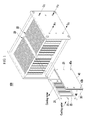
- FIG. 1 is a perspective view of a fuel cell stack according to an exemplary embodiment of the present invention.
- a fuel cell stack 100 includes a plurality of electricity generation units 20 as cell units for electrochemically reacting a fuel and oxygen to generate electrical energy. That is, a plurality of electricity generation units 20 are continuously disposed and coupled in series to each other thereby forming the fuel cell stack 100.
- the fuel may be a liquid fuel or a gas fuel including hydrogen such as methanol, ethanol, liquefied petroleum gas (LPG), liquefied natural gas (LNG), and gasoline.
- the fuel cell stack 100 is formed as a direct oxidation fuel cell type generating electrical energy by a direct reaction of the liquid fuel or the gas fuel and oxygen.
- the fuel may include hydrogen cracked from the liquid fuel or the gas fuel through a general reformer.
- the fuel cell stack 100 is formed as a polymer electrode membrane fuel cell type generating electrical energy by a reaction of hydrogen and oxygen.
- FIG. 2 is an exploded perspective view showing an electricity generation unit in the fuel cell stack shown in FIG. 1 .
- the electricity generation unit 20 includes a membrane-electrode assembly 30 and a pair of separators 40 positioned closely adjacent to both surface of the membrane-electrode assembly 30.
- FIG. 3 is a disassembled cross-sectional view of the electricity generation unit shown in FIG. 2
- FIG. 4 is an assembled cross-sectional view of the electricity generation unit shown in FIG. 2
- the membrane-electrode assembly 30 includes an electrolyte layer 31, an anode 32 positioned at one surface of the electrolyte layer 31, a cathode 33 positioned at the other surface of the electrolyte layer 31, and a gas diffusion layer 34 positioned at outer surfaces of the anode 32 and the cathode 33.
- the anode 32 divides the provided fuel into electrons and protons, and the electrolyte layer 31 moves the protons to the cathode 33.
- the cathode 33 reacts the electrons and protons transmitted from the electrolyte layer 31 and separately provided oxygen to generate moisture and heat.
- the gas diffusion layer 34 has a function of uniformly supplying the fuel to the anode 32 and the oxygen to the cathode 33.
- a gasket 35 is positioned according to an edge of the membrane-electrode assembly 30.
- the gasket 35 supports the membrane-electrode assembly 30 and maintains air-tightness between the separator 40 and the membrane-electrode assembly 30.
- the gasket 35 may be made of silicon rubber having elasticity or a polymer material such as PET.
- the separators 40 disposed at both surfaces of the membrane-electrode assembly 30 have functions of supporting and dispersing the fuel to the anode 32 and the oxygen to the cathode 33.
- the separator 40 includes a channel 41 to receive the fuel or oxygen and to uniformly supply them to the membrane-electrode assembly 30.
- the separator 40 includes a main body 42 of a plate shape, the channel 41 concavely formed at one surface of the main body 42 toward the membrane-electrode assembly 30 and providing a moving path for the fuel or oxygen, and manifolds 43a and 43b connected to the channel 41 while being positioned at the edge of the main body 42 and supplying the fuel or oxygen to the channel 41.
- the main body 42 may be made of a carbon material such as graphite, or a metal.
- the manifolds 43a and 43b include a pair of fuel manifolds 43a providing the fuel and a pair of oxygen manifolds 43b supplying oxygen.
- the channel 41 of the separator 40 facing the anode 32 is connected to a pair of fuel manifolds 43a, and the channel 41 of the separator 40 facing the cathode 33 is connected to a pair of oxygen manifolds 43b.
- the separator 40 facing the anode 32 is shown at the left side and the separator 40 facing the cathode 33 is shown at the right side.
- FIG. 2 shows an example of the separator 40 of a structure in which a plurality of ribs 44 are disposed with an interval therebetween at one surface of the main body 42 toward the membrane-electrode assembly 30 thereby forming a plurality of channels 41 between the ribs 44, and ends of the channels 41 are connected to each other.
- the shape of the channel 41 is not limited to the above-described example, and all shapes that are capable of providing the moving path of the fuel or oxygen may be applied.
- a metal layer 46 including minute grooves 45 of a nano-scale and forming the surface of the channel 41 with a super-hydrophilicity is positioned on the surface of the channel 41.
- the surface of the channel 41 means the entire surface of the channel 41 including a bottom surface 411 and a side surface 412 (shown in an enlarged circle of FIG. 3 ), and the nano-scale means a size range of more than 1 nm and less than 1000 nm.
- An oxide layer 47 is formed at the surface of the metal layer 46, and the minute grooves 45 of the nano-scale are positioned at the oxide layer 47.
- the oxide layer 47 and the minute grooves 45 are formed through an anodic oxidation process that will be described later.
- the metal layer 46 may be formed of aluminum, and the oxide layer 47 may be formed of aluminum oxide.
- a general metal is a hydrophilic material having a contact angle with a liquid of less than 90°. If the minute grooves 45 of the nano-scale are formed at the surface of the metal layer 46, the contact angle is decreased to less than 5° such that the hydrophilicity is maximized.
- the minute grooves 45 may have a diameter of 20 nm to 200 nm and an aspect ratio in a range of more than 10 to less than 2000.
- the aspect ratio is high so as to present good hydrophilicity, however if the aspect ratio is less than 10, the hydrophilicity is weak.
- the hydrophilicity causes the aspect ratio to be large, however the hydrophilicity is not largely enhanced if the aspect ratio is over 2000, , so when considering process time, it is preferable for the aspect ratio of the minute grooves 45 to be less than 2000.
- the channel 41 including the metal layer 46 has a super-hydrophilic surface because of the minute grooves 45 such that water generated in the membrane-electrode assembly 30 during fuel cell operation is deposited to the channel 41 and is directly absorbed to the surface of the channel 41 formed with the minute grooves 45.
- the separator 40 may smoothly provide the fuel and oxygen to the anode 32 and the cathode 33 while minimizing a moving disturbance of the fuel and hydrogen, and as a result, chemical reaction efficiency of the fuel cell may be increased.
- the metal layer 46 is formed on the entire surface of the channel 41 and is not provided to the surface of the rib 44 positioned close to the membrane-electrode assembly 30.
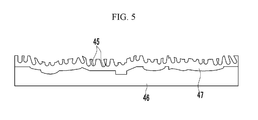
- FIG. 5 is an enlarged cross-sectional view according to another exemplary embodiment of the metal layer shown in FIG. 4 .
- the metal layer 46 forms minute protrusions and depressions of a micro-scale.
- the oxide layer 47 is formed according to the minute protrusions and depressions of the micro-scale, and thereby the minute grooves 45 of the nano-scale are formed on the surface thereof.
- the micro-scale means a size included in a range of more than 1 ⁇ m to less than 1000 ⁇ m.
- the minute protrusions and depressions of the micro-scale have a function of increasing the hydrophilicity of the surface of the channel 41.
- the minute protrusions and depressions may be formed by a method of injecting minute particles to the surface of the metal layer 46 by using compressed air pressure. That is, the surface of the metal layer 46 is changed by collision energy of the minute particles, thereby forming the minute protrusions and depressions of the micro-size.
- a cooling plate 21 providing cooling water to the electricity generation unit 20 may be provided.
- the cooling plate 21 forms a channel 22 for moving the cooling water at one surface thereof.
- a cooling water manifold 23 supplying the cooling water is formed at the edge of the cooling plate 21, the separator 40, and the gasket 35, and the channel 22 of the cooling plate 21 is connected to the cooling water manifold 23.
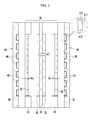
- One membrane-electrode assembly 30 and two separators 40 may form one electricity generation unit 20. Meanwhile, as shown in FIG. 6 , channels 41 are formed at both surfaces of the separator 40, thereby one separator 40 is disposed between two neighboring membrane-electrode assemblies 30. In this case, the metal layer 46 including the minute grooves of the nano-scale is formed on the surface of the channels 41 to form the surface of the channels 41 having super-hydrophilicity.
- FIG. 7 is a process flowchart of a manufacturing method of a separator for a fuel cell according to an exemplary embodiment of the present invention.
- a manufacturing method of the separator for the fuel cell includes a first step S100 of forming a concave channel in at least one surface of the main body, a second step S200 of forming a mask layer on the surface of the main body except for the channel, a third step S300 of depositing a metal on the surface of the channel to form a metal layer, a fourth step S400 of injecting minute particles to the metal layer to form minute protrusions and depressions of the micro-scale, a fifth step S500 of forming an oxide layer and minute grooves of the nano-scale through an anodic oxidation treatment of the metal layer, and a sixth step S600 of removing the mask layer. If necessary, the fourth step S400 may be omitted.
- FIG. 8 is a cross-sectional view showing the separator of the first step shown in FIG. 7 .
- a main body 42 made of a carbon material or a metal is manufactured.
- the main body 42 may be manufactured by an extrusion molding method using a mold, and a convex portion corresponding to the shape of the channel 41 is formed to simultaneously form the main body 42 and the channel 41.
- the main body 42 is processed through a stamping process to form a concave channel 41.
- FIG. 9 is a cross-sectional view showing the separator of the second step shown in FIG. 7 .
- a mask layer 50 is formed on the surface of the main body 42 except for the channel 41. That is, the mask layer 50 is formed on the entire surface of the ribs 44 facing the membrane-electrode assembly 30 such that only the channel 41 is exposed outside.
- minute protrusions and depressions and minute grooves may only be formed in the surface of the channel 41.
- FIG. 10 is a cross-sectional view showing the separator of the third step shown in FIG. 7 .
- a metal such as aluminum is deposited on the surface of the channel 41 to form a metal layer 46.
- the ribs 44 are covered by the mask layer 50 such that the metal layer 46 is not formed on the surface of the ribs 44.
- FIG. 11 A is a schematic diagram showing an injector used in the fourth step of FIG. 7
- FIG. 11 B is an enlarged cross-sectional view showing a metal layer after the fourth step.
- an injector 60 injects minute particles with a predetermined speed toward the metal layer 46 of the separator 40.
- the injector 60 may be a pneumatic injector using compressed air pressure, and may control injection speed and injection pressure of the minute particles by controlling a pressure of the air.
- the injector 60 may be connected to an compressed air supply unit 61, a pressure controller 62 controlling the pressure of the air, a storing unit 63 storing the minute particles 63, and a pump 64 supplying the minute particles to the injector 60.
- the minute particles collide with the surface of the metal layer 46 thereby causing deformation of the surface of the metal layer 46.
- minute protrusions and depressions 48 of the micro-scale are formed in the surface of the metal layer 46.
- the minute particles may be metal balls, sand particles, or sodium hydrogen carbonate particles, referred to as baking soda.
- the minute particles may have a diameter of 10 ⁇ m to 50 ⁇ m. If the size of the minute particles is less than 10 ⁇ m, it is difficult to form the minute protrusions and depressions 48 of the micro-scale, and if the size is over 50 ⁇ m, the size of the minute protrusions and depressions 48 is increased such that the hydrophilicity of the metal layer 46 is deteriorated.
- the minute particles are hydrosoluble sodium hydrogen carbonate particles
- the minute particles are injected to form the minute protrusions and depressions 48, and then the metal layer 46 is cleaned with water such that the minute particles attached to the surface of the metal layer 46 may be easily removed.
- the metal layer 46 may be cleaned at least once if necessary in the middle process of the fourth step S400. If the hydrosoluble minute particles are used, foreign materials remaining on the surface of the metal layer 46 may be effectively suppressed.
- the hydrosoluble minute particles and dry ice may be injected together using the injector 60.
- the dry ice collides with the surface of the metal layer 46 moisture is generated because of the temperature difference with the metal layer 46, and the hydrosoluble minute particles are dissolved by this moisture.
- the mixture of the water and the hydrosoluble minute particles may be easily removed from the surface of the metal layer 46 by using injection pressure of the injector 60. Accordingly, a water cleaning process for the metal layer 46 may be omitted such that the entire process may be simplified.
- the size of the minute protrusions and depressions 48 that is, a height of a protrusion portion 481, a depth of the depression portion 482, or an interval between the protrusion portions 481 may be changed according to the kind of minute particles, the diameter, the injection speed, and the injection pressure, and the shape of the minute protrusions and depressions 48 may be controlled by appropriately controlling these.
- FIG. 12 is a schematic diagram showing an anodic oxidation device used in the fifth step of FIG. 7 .
- the anodic oxidation device 70 includes a circulation bath 71 in which cooling water is circulated, and a magnetic agitator 72 agitating an electrolyte solution in the bath 71 at a predetermined speed.
- the channels of the separator 40 and a counter electrode 73 are soaked to the electrolyte solution in the bath 71, and the separator 40 and the counter electrode 73 are respectively applied with a positive voltage and a negative voltage to perform the anodic oxidation process.
- the electrolyte solution may include phosphoric acid (H 3 PO 4 ) or oxalic acid (C 2 H 2 O 4 ), and the counter electrode 73 may be platinum (Pt) or aluminum (Al).
- the minute grooves 45 may be formed through an anodic oxidation treatment for 110 minutes in the electrolyte solution under the conditions of 0.3 M of oxalic acid, a 40 V voltage, and a 15 °C temperature.
- the anodic oxidation treatment may be performed for 10 minutes in the electrolyte solution under the conditions of 0.1 M of phosphoric acid, 165 V to a 195 V voltage, and a 0.1 °C to 2 °C temperature to expand the diameter of the minute grooves 45.
- the fourth step S400 may be omitted, and the metal layer 46 may directly undergo the anodic oxidation treatment.
- the anodic oxidation treatment is performed for 24 hours in the electrolyte solution under the conditions of 0.3 M of oxalic acid, a voltage of 40V, and a temperature of 24 °C to 30 °C 24, thereby forming the oxide layer 47 and the minute grooves 45 on the metal layer 46.
- the oxide layer 47 is formed on the surface of the metal layer 46 and the minute grooves of the nano-scale are formed in the oxide layer 47.
- the oxide layer 47 and the minute grooves 45 are formed according to the minute protrusions and depressions.
- the diameter and depth of the minute grooves 45 may be controlled by controlling the concentration of the electrolyte solution, the application voltage intensity, or the etching time.
- the mask layer 50 is removed to remove the separators 40.
- FIG. 13 is a view showing an experimental result of a contact angle formed by dripping a water drop on a surface of a metal layer for a separator in which minute protrusions and depressions and minute grooves are formed in a metal layer
- FIG. 14 is a view showing an experimental result of a contact angle formed by dripping a water drop on a surface of a metal layer for a separator in which minute grooves are only formed in a metal layer.
- the left view shows a state before the water drop is dripped
- the right view shows a state after the water drop is dripped.
- the bar in the upper part of the drawing represents an apparatus used to drip the water drop.
- the separator of the present exemplary embodiment forms a channel having a super-hydrophilic surface such that the water is directly absorbed in the membrane-electrode assembly, and thereby the efficiency of transmitting the fuel and the air is improved.
- the chemical reaction efficiency of the fuel cell stack is increased such that a large amount of electrical energy may be generated.
Landscapes
- Chemical & Material Sciences (AREA)
- Life Sciences & Earth Sciences (AREA)
- Engineering & Computer Science (AREA)
- Manufacturing & Machinery (AREA)
- Sustainable Development (AREA)
- Sustainable Energy (AREA)
- Chemical Kinetics & Catalysis (AREA)
- Electrochemistry (AREA)
- General Chemical & Material Sciences (AREA)
- Composite Materials (AREA)
- Fuel Cell (AREA)
Applications Claiming Priority (2)
| Application Number | Priority Date | Filing Date | Title |
|---|---|---|---|
| KR1020090091832A KR101100858B1 (ko) | 2009-09-28 | 2009-09-28 | 연료 전지용 세퍼레이터와 이의 제조 방법 및 이를 포함하는 연료 전지 스택 |
| PCT/KR2010/006544 WO2011037428A2 (ko) | 2009-09-28 | 2010-09-27 | 연료 전지용 세퍼레이터와 이의 제조 방법 및 이를 포함하는 연료 전지 스택 |
Publications (2)
| Publication Number | Publication Date |
|---|---|
| EP2485309A2 true EP2485309A2 (de) | 2012-08-08 |
| EP2485309A4 EP2485309A4 (de) | 2014-01-15 |
Family
ID=43796402
Family Applications (1)
| Application Number | Title | Priority Date | Filing Date |
|---|---|---|---|
| EP10819069.5A Withdrawn EP2485309A4 (de) | 2009-09-28 | 2010-09-27 | Separator für eine brennstoffzelle, herstellungsverfahren dafür und brennstoffzellenstapel damit |
Country Status (5)
| Country | Link |
|---|---|
| US (1) | US9219281B2 (de) |
| EP (1) | EP2485309A4 (de) |
| KR (1) | KR101100858B1 (de) |
| CN (1) | CN102576883B (de) |
| WO (1) | WO2011037428A2 (de) |
Cited By (1)
| Publication number | Priority date | Publication date | Assignee | Title |
|---|---|---|---|---|
| WO2020212128A1 (de) * | 2019-04-17 | 2020-10-22 | Robert Bosch Gmbh | Bipolarplatte für eine brennstoffzelle, verfahren zur herstellung einer bipolarplatte und brennstoffzelle |
Families Citing this family (3)
| Publication number | Priority date | Publication date | Assignee | Title |
|---|---|---|---|---|
| KR101349076B1 (ko) * | 2011-07-20 | 2014-01-14 | 현대자동차주식회사 | 연료전지 스택용 매니폴드 블록의 산화층 형성 장치 및 방법 |
| KR101395419B1 (ko) * | 2012-06-05 | 2014-05-15 | 현대하이스코 주식회사 | 반응면에서의 습기 제거력이 우수한 연료전지용 분리판 제조 방법 |
| JP7081307B2 (ja) * | 2018-05-28 | 2022-06-07 | トヨタ紡織株式会社 | 燃料電池用セパレータ |
Family Cites Families (11)
| Publication number | Priority date | Publication date | Assignee | Title |
|---|---|---|---|---|
| CA1341327C (en) * | 1989-09-05 | 2001-12-18 | Dan Fern | Methods for depositing finish coatings on substrates of anodisable metals and the products thereof |
| KR100714385B1 (ko) | 2000-09-12 | 2007-05-04 | 닛신 세이코 가부시키가이샤 | 저온형 연료전지용 세퍼레이터 및 그 제조 방법 |
| JP3857873B2 (ja) * | 2000-11-09 | 2006-12-13 | 三洋電機株式会社 | 燃料電池用セパレータとその製造方法、および燃料電池 |
| ATE324673T1 (de) | 2002-11-18 | 2006-05-15 | Gencell Corp | Bipolarplatte mit zwei-durchgängen-anode |
| KR100669373B1 (ko) | 2004-11-25 | 2007-01-15 | 삼성에스디아이 주식회사 | 연료전지용 금속 세퍼레이터 및 그 제조방법과 이를포함하는 연료전지 |
| WO2007016779A1 (en) * | 2005-08-09 | 2007-02-15 | The University Of British Columbia | Microporous metals and methods for hydrogen generation from water split reaction |
| US8389174B2 (en) * | 2006-01-27 | 2013-03-05 | GM Global Technology Operations LLC | Super-hydrophilic nanoporous electrically conductive coatings for PEM fuel cells |
| US20080044716A1 (en) | 2006-08-16 | 2008-02-21 | Gm Global Technology Operations, Inc. | Durable layer structure and method for making same |
| KR101002044B1 (ko) * | 2008-01-15 | 2010-12-17 | 한국과학기술연구원 | 초소형 연료전지 및 그 제조 방법과 이를 이용한 초소형연료전지 스택 |
| DE102008006038B4 (de) | 2008-01-25 | 2013-02-21 | Elringklinger Ag | Verfahren zur Herstellung einer Bipolarplatte für eine Brennstoffzelleneinheit und Bipolarplatte |
| US9136545B2 (en) * | 2008-02-27 | 2015-09-15 | GM Global Technology Operations LLC | Low cost fuel cell bipolar plate and process of making the same |
-
2009
- 2009-09-28 KR KR1020090091832A patent/KR101100858B1/ko not_active Expired - Fee Related
-
2010
- 2010-09-27 EP EP10819069.5A patent/EP2485309A4/de not_active Withdrawn
- 2010-09-27 CN CN201080043051.2A patent/CN102576883B/zh not_active Expired - Fee Related
- 2010-09-27 US US13/498,479 patent/US9219281B2/en not_active Expired - Fee Related
- 2010-09-27 WO PCT/KR2010/006544 patent/WO2011037428A2/ko not_active Ceased
Cited By (1)
| Publication number | Priority date | Publication date | Assignee | Title |
|---|---|---|---|---|
| WO2020212128A1 (de) * | 2019-04-17 | 2020-10-22 | Robert Bosch Gmbh | Bipolarplatte für eine brennstoffzelle, verfahren zur herstellung einer bipolarplatte und brennstoffzelle |
Also Published As
| Publication number | Publication date |
|---|---|
| CN102576883B (zh) | 2015-02-18 |
| EP2485309A4 (de) | 2014-01-15 |
| US20120183882A1 (en) | 2012-07-19 |
| CN102576883A (zh) | 2012-07-11 |
| WO2011037428A3 (ko) | 2011-08-18 |
| WO2011037428A2 (ko) | 2011-03-31 |
| KR20110034335A (ko) | 2011-04-05 |
| KR101100858B1 (ko) | 2012-01-02 |
| US9219281B2 (en) | 2015-12-22 |
Similar Documents
| Publication | Publication Date | Title |
|---|---|---|
| US10998557B2 (en) | Separator for fuel cell, manufacturing method thereof, and fuel cell having such a separator | |
| EP2475036B1 (de) | Membranelektrodenanordnung, herstellungsverfahren dafür und brennstoffzelle | |
| EP1265303A1 (de) | Polymer-elektroly-brennstoffzelle und herstellungsverfahren dafür | |
| US12080921B2 (en) | Distributor structure for a fuel cell or electrolyser | |
| CN112133937B (zh) | 质子交换膜燃料电池流道结构及质子交换膜燃料电池 | |
| WO2021213497A1 (zh) | 一种带有表面微结构的燃料电池金属极板及其制造方法 | |
| WO2006121157A1 (ja) | 燃料電池 | |
| US9219281B2 (en) | Separator for a fuel cell, a production method therefor and a fuel cell stack comprising the same | |
| CN108091900A (zh) | 利用凸缘近邻处的压制压纹减少压力变化 | |
| JP2001283873A (ja) | 高分子電解質型燃料電池用セパレータとその製造法およびこれを用いた高分子電解質型燃料電池 | |
| US7396609B2 (en) | Fuel cell and metal separator for fuel cell | |
| US7572538B2 (en) | Fuel cell | |
| KR20200134524A (ko) | 연료전지 스택 | |
| KR100619193B1 (ko) | 연료 전지 및 연료 전지용 세퍼레이터 | |
| CN116130700A (zh) | 燃料电池双极板及燃料电池电堆 | |
| JP4561239B2 (ja) | 燃料電池セパレータおよびそれを用いた燃料電池 | |
| US20110086288A1 (en) | Fuel cell structure with porous metal plate | |
| US20240039012A1 (en) | Discrete microchannels and microstructures embedded in metal foam gas diffusion layer for pem fuel cells | |
| CN101714643B (zh) | 用于实现带有超薄电极的燃料电池的高中温性能的材料设计 | |
| KR101926454B1 (ko) | 연료전지 분리판 및 이를 갖는 연료전지 스택 | |
| CN117543025B (zh) | 一种氢燃料电池阳极板脊梯度化设计方法及其结构 | |
| CN112470313A (zh) | 用于燃料电池的双极板以及燃料电池 | |
| KR20250059191A (ko) | 금속분리판 및 이를 포함하는 연료전지 셀 | |
| KR20070094129A (ko) | 연료 전지용 세퍼레이터 및 이를 포함하는 연료 전지 스택 | |
| KR20110061005A (ko) | 가스켓 성형방법 및 연료전지용 가스켓 사출금형 |
Legal Events
| Date | Code | Title | Description |
|---|---|---|---|
| PUAI | Public reference made under article 153(3) epc to a published international application that has entered the european phase |
Free format text: ORIGINAL CODE: 0009012 |
|
| 17P | Request for examination filed |
Effective date: 20120413 |
|
| AK | Designated contracting states |
Kind code of ref document: A2 Designated state(s): AL AT BE BG CH CY CZ DE DK EE ES FI FR GB GR HR HU IE IS IT LI LT LU LV MC MK MT NL NO PL PT RO SE SI SK SM TR |
|
| DAX | Request for extension of the european patent (deleted) | ||
| A4 | Supplementary search report drawn up and despatched |
Effective date: 20131216 |
|
| RIC1 | Information provided on ipc code assigned before grant |
Ipc: H01M 8/02 20060101AFI20131210BHEP Ipc: H01M 8/24 20060101ALI20131210BHEP |
|
| 17Q | First examination report despatched |
Effective date: 20150112 |
|
| STAA | Information on the status of an ep patent application or granted ep patent |
Free format text: STATUS: THE APPLICATION IS DEEMED TO BE WITHDRAWN |
|
| 18D | Application deemed to be withdrawn |
Effective date: 20180404 |