EP2484913A2 - Turbomachine comportant un boîtier annulaire et rotor à pales - Google Patents
Turbomachine comportant un boîtier annulaire et rotor à pales Download PDFInfo
- Publication number
- EP2484913A2 EP2484913A2 EP12152509A EP12152509A EP2484913A2 EP 2484913 A2 EP2484913 A2 EP 2484913A2 EP 12152509 A EP12152509 A EP 12152509A EP 12152509 A EP12152509 A EP 12152509A EP 2484913 A2 EP2484913 A2 EP 2484913A2
- Authority
- EP
- European Patent Office
- Prior art keywords
- groove
- grooves
- turbomachine
- blade
- depth
- Prior art date
- Legal status (The legal status is an assumption and is not a legal conclusion. Google has not performed a legal analysis and makes no representation as to the accuracy of the status listed.)
- Granted
Links
Images

Classifications
-
- F—MECHANICAL ENGINEERING; LIGHTING; HEATING; WEAPONS; BLASTING
- F04—POSITIVE - DISPLACEMENT MACHINES FOR LIQUIDS; PUMPS FOR LIQUIDS OR ELASTIC FLUIDS
- F04D—NON-POSITIVE-DISPLACEMENT PUMPS
- F04D27/00—Control, e.g. regulation, of pumps, pumping installations or pumping systems specially adapted for elastic fluids
- F04D27/02—Surge control
-
- F—MECHANICAL ENGINEERING; LIGHTING; HEATING; WEAPONS; BLASTING
- F01—MACHINES OR ENGINES IN GENERAL; ENGINE PLANTS IN GENERAL; STEAM ENGINES
- F01D—NON-POSITIVE DISPLACEMENT MACHINES OR ENGINES, e.g. STEAM TURBINES
- F01D11/00—Preventing or minimising internal leakage of working-fluid, e.g. between stages
- F01D11/08—Preventing or minimising internal leakage of working-fluid, e.g. between stages for sealing space between rotor blade tips and stator
-
- F—MECHANICAL ENGINEERING; LIGHTING; HEATING; WEAPONS; BLASTING
- F01—MACHINES OR ENGINES IN GENERAL; ENGINE PLANTS IN GENERAL; STEAM ENGINES
- F01D—NON-POSITIVE DISPLACEMENT MACHINES OR ENGINES, e.g. STEAM TURBINES
- F01D25/00—Component parts, details, or accessories, not provided for in, or of interest apart from, other groups
- F01D25/24—Casings; Casing parts, e.g. diaphragms, casing fastenings
-
- F—MECHANICAL ENGINEERING; LIGHTING; HEATING; WEAPONS; BLASTING
- F04—POSITIVE - DISPLACEMENT MACHINES FOR LIQUIDS; PUMPS FOR LIQUIDS OR ELASTIC FLUIDS
- F04D—NON-POSITIVE-DISPLACEMENT PUMPS
- F04D29/00—Details, component parts, or accessories
- F04D29/08—Sealings
- F04D29/16—Sealings between pressure and suction sides
- F04D29/161—Sealings between pressure and suction sides especially adapted for elastic fluid pumps
- F04D29/164—Sealings between pressure and suction sides especially adapted for elastic fluid pumps of an axial flow wheel
-
- F—MECHANICAL ENGINEERING; LIGHTING; HEATING; WEAPONS; BLASTING
- F04—POSITIVE - DISPLACEMENT MACHINES FOR LIQUIDS; PUMPS FOR LIQUIDS OR ELASTIC FLUIDS
- F04D—NON-POSITIVE-DISPLACEMENT PUMPS
- F04D29/00—Details, component parts, or accessories
- F04D29/40—Casings; Connections of working fluid
- F04D29/52—Casings; Connections of working fluid for axial pumps
- F04D29/522—Casings; Connections of working fluid for axial pumps especially adapted for elastic fluid pumps
- F04D29/526—Details of the casing section radially opposing blade tips
-
- F—MECHANICAL ENGINEERING; LIGHTING; HEATING; WEAPONS; BLASTING
- F04—POSITIVE - DISPLACEMENT MACHINES FOR LIQUIDS; PUMPS FOR LIQUIDS OR ELASTIC FLUIDS
- F04D—NON-POSITIVE-DISPLACEMENT PUMPS
- F04D29/00—Details, component parts, or accessories
- F04D29/66—Combating cavitation, whirls, noise, vibration or the like; Balancing
- F04D29/68—Combating cavitation, whirls, noise, vibration or the like; Balancing by influencing boundary layers
- F04D29/681—Combating cavitation, whirls, noise, vibration or the like; Balancing by influencing boundary layers especially adapted for elastic fluid pumps
- F04D29/685—Inducing localised fluid recirculation in the stator-rotor interface
-
- F—MECHANICAL ENGINEERING; LIGHTING; HEATING; WEAPONS; BLASTING
- F05—INDEXING SCHEMES RELATING TO ENGINES OR PUMPS IN VARIOUS SUBCLASSES OF CLASSES F01-F04
- F05D—INDEXING SCHEME FOR ASPECTS RELATING TO NON-POSITIVE-DISPLACEMENT MACHINES OR ENGINES, GAS-TURBINES OR JET-PROPULSION PLANTS
- F05D2250/00—Geometry
- F05D2250/10—Two-dimensional
- F05D2250/18—Two-dimensional patterned
- F05D2250/184—Two-dimensional patterned sinusoidal
Definitions
- This invention relates to a turbomachine comprising an annular casing and a bladed rotor, and is particularly, although not exclusively, concerned with a turbomachine in the form of a compressor or a fan in a gas turbine engine.
- a gas turbine engine typically has a series of compressor stages which compress incoming air before it is combusted and exhausted through turbine stages, which drive the compressor stages.
- a turbine-driven ducted fan may provide a substantial proportion of the propulsive thrust of the engine by delivering air directly into the surrounding air stream, without passing through the combustor and turbine stages of the engine.
- the compressor stages and fans comprise bladed rotors which rotate within casings.
- the expression "rotor" embraces rotors of both compressors and fans.
- any casing treatment grooves In order to enhance the efficiency of an engine, it is desirable for any casing treatment grooves to be no deeper than necessary to achieve the desired aerodynamic improvements. While the helical grooves disclosed in EP1801361 vary in depth along their length, the purpose of the depth variation is to improve the ejection of debris from the grooves, and is not related to the aerodynamic requirements at the blade tips.
- a turbomachine comprising an annular casing and a bladed rotor which is rotatable within the casing, each blade of the rotor having a leading edge and a trailing edge, and a blade tip which travels over a swept region of an internal surface of the casing, the swept region being provided with a series of axially spaced circumferential grooves, at least two of the grooves having different depths from each other.
- the depths of the grooves may decrease monotonically from a groove having a maximum depth to a groove at the end of the series corresponding to the trailing edge of the blade.
- the depth of the grooves may be decrease monotonically from the groove of maximum depth to a groove at the end of the series corresponding to the leading edge of the blade.
- the axial chord (AC) of each blade is the axial distance, measured in a direction parallel to the rotary axis of the rotor, between the leading edge and the trailing edge.
- the depth of the groove of maximum depth may be not less than 15% and not more than 20% of the axial chord of the blade.
- the depth of the groove of minimum depth may be not less than 0.5 % and not more than 2% of the axial chord.
- the groove of minimum depth may be the groove at the end of the series corresponding to the leading edges of the blades.
- the groove at the end of the series corresponding the trailing edges of the blades may have a depth which is not less than 10% and not more than 18% of the axial chord.
- the gaps between adjacent ones of the grooves may have a substantially similar width across the series of grooves. This width may be not less than 6% and not more than 7% of the axial chord, particularly if the series comprises five grooves.
- the gap between one pair of adjacent grooves may be slightly larger, for example 4% to 6% larger, than the gaps between other pairs of adjacent grooves.
- the pair of adjacent grooves having the larger gap may be situated not less than 30% and not more than 50% of the axial chord from the leading edges of the blades.
- the forward most groove may be situated not less than 12% and not more than 16% of the axial chord from the leading edges of the blades.
- the aft most groove may be situated not less than 70% and not more than 80% of the axial chord from the leading edges of the blades.
- the grooves may extend in the radial direction at an angle which is not less than 65° and not more than 95° to the rotational axis of the rotor. For some rotors, enhanced results are achieved if the angle of the groove is not less than 68° and not more than 75°. Another possible range of angles is from 85° to 95°, for example 90°.
- the present invention also provides a gas turbine engine having a fan or compressor as defined above.
- FIG. 1 A gas turbine turbofan engine having a high by-pass ratio of the kind used to power commercial airliners and transport aircraft is illustrated in Figure 1 as an example only of one type of engine in which the invention may be used. It is to be understood that it is not intended thereby to limit use of the invention to engines of that type. The invention will find application in turbojet engines in which the bypass ratio is very much less than a turbofan. Nor is it intended by illustrating an axial flow engine to exclude the invention from use with radial flow engines. Furthermore, although the invention is described below in connection with an engine, it need not inevitably be part of an engine and could be simply a rotary compressor or fan.
- the engine shown comprises a core, axial flow combustion section generally indicated at 2 and a fan section 4.
- the fan section 4 comprises an array of unshrouded fan blades 6 mounted around the periphery of a rotor disc 8 housed within an annular fan casing 10.
- the fan casing 10 is generally cylindrical and its inner surface 12 ( Figure 2 ) defines the radially outer wall of the flow path through the fan stage.
- the inner surface 12 of the casing 10 is spaced by a running clearance from the radially outer tips 14 of the rotor blades 6. The running clearance depends on several factors and varies under centrifugal loading and with temperature throughout an engine cycle.
- a build clearance is selected to ensure that the blade tips 14 do not rub the casing inner surface 12 when the engine is stationary or turning at low speed. As engine speed increases the clearance tends to reduce due to creep in the length of the blade under the influence of centrifugal forces. Thermal effects on the casing 10 and the rotor blades also have to be taken into account.
- the efficiency of the fan rotor is influenced partly by the size of the running clearance.
- the initial build clearance is set so that a tip rub is achieved at a predetermined engine speed.
- a sacrificial insert is set into the fan casing wall arranged to contact the blade tips 14 which then cut a track in the insert surface.
- stall margin Another important fan performance factor is the stall margin. At the onset of stall conditions, mass flow through the fan is significantly reduced, and complete flow reversal can occur, a phenomenon known as surge. Fan or compressor surge in a gas turbine engine can have a catastrophic effect on the operation of the engine. It is therefore essential that the operating envelope of the engine is restricted to ensure that stall does not occur.
- the stall margin, or stability margin represents the area between the normal working line of the fan or compressor and the stability line at which the onset of stall occurs. Consequently an improvement in the stall margin serves either to reduce the likelihood of stall during transient engine operation, or to enable the working line to be raised to increase the design performance of the engine.
- Blade stall may be initiated by a reduction in the mass flow rate of air through the blades.
- the incoming air meets the radially outer tips 14 of the blades at a high angle of incidence, which can lead to separation of the flow from the suction side of the blades and the onset of stall.
- the casing wall may be designed with so-called casing treatments that remove or re-circulate a proportion of the boundary layer, thus delaying or preventing onset of the airflow stall conditions.
- FIG. 2 A casing treatment in accordance with the present invention is shown in Figure 2 .
- the description above has referred specifically to the fan section 4, it will be appreciated that the same considerations apply also to compressor rotors of the core section 2. Consequently, references to the casing 10 and the blades 6 as shown in Figures 2 , 3a and 3b apply equally to fan and compressor rotors and casings.
- the casing 10 is represented only by the inner surface 12 of the casing 10, but it will be appreciated that the casing itself will typically have a radial thickness extending outwardly of the surface 12.
- the casing treatment comprises a series of grooves 16A, 16B, 16C, 16D and 16E.
- grooves 16A, 16B, 16C, 16D and 16E there are five grooves in the embodiment shown in Figure 2 , but it will be appreciated that other numbers of grooves may be appropriate, depending on the overall configuration of the rotor section 4.
- Each of the grooves 16 is a circumferential groove, constituting a single ring extending around the array of blades 6. As shown in Figure 2 , the grooves 16 are of rectangular form having a depth d (shown only for the grooves 16C). Each groove has an axial thickness t (again shown only for the groove 16C), and adjacent grooves are spaced apart by gaps 18A, 18B, 18C, 18D, having a width w.
- Each blade 6 has a leading edge 20 and a trailing edge 22 which are projected onto the inner surface 12 at positions represented by points 24, 26.
- each blade tip 14 travels over a swept region of the surface 12, which swept region is a circumferential path having axial ends which are defined by circles passing through the points 24, 26.
- the series of grooves 16 lies entirely within the swept region so that the forward most groove 16A is aft of the leading edge 20, and the aft most groove 16E is forward of the trailing edge 22.
- the distance a between the leading edge circle passing through the point 24 and the forward most groove 16A is in the range 12% to 16% of the axial chord of the blade 6 (i.e. the axial distance between the points 24 and 26).
- the distance a may be 14% to 15% of the axial chord.
- the corresponding distance to the aft most groove 16E may, for example, be in the range 70% to 80% of the axial chord.
- the measurement is taken from the points 24 to the forward most edge of the respective groove 16.
- the depths d of the grooves 16 differ over the series of grooves.
- the central groove 16C has the maximum depth d and the depths d of the grooves to either side of the maximum depth groove 16C decrease monotonically towards the leading and trailing edges 20, 22 of the blade 6 respectively.
- the groove 16A and 16B forward of the groove 16C have substantially smaller depths than the grooves 16D and 16E aft of the groove 16C for reasons which will be described below.
- the depths of the grooves 16 may be as follows, with the depths being expressed as a percentage of the axial chord (%AC):
- the uniform thickness t of the grooves may be 8.3%AC.
- the casing treatment shown in Figure 2 with the dimensions referred to above was derived following computational fluid dynamics (CFD) modelling of a transonic rotor known as NASA rotor 37, followed by a subsequent optimisation process.
- CFD computational fluid dynamics
- the casing treatment of Figure 2 was compared with models representing a rotor with no casing treatment (i.e. a plain cylindrical inner surface 12), and a reference casing treatment model in which the grooves 16 have equal depths of 3.6%AC and a groove width of 8%AC.
- Table 1 demonstrates that the optimum groove configuration of Figure 2 provides an improvement in stall margin (SM) comparable to that of a series of equal-depth grooves, but with a lower penalty in peak efficiency ( ⁇ Peak %).
- SM stall margin
- the width w of the gap between adjacent grooves 16 was varied, but a common gap size was maintained between all adjacent groove pairs.
- the width w was 6%AC.
- Simulations were run in which each of the gaps 18A, 18B, 18C and 18D were enlarged in turn to a width w of 6.3%AC. The remaining gaps remained at a width w of 6%AC.
- Table 3 Width w of gaps between grooves %AC: case 18A 18B 18C 18D ⁇ SM 1 6.3 6 6 6 0.72 2 6 6.3 6 6 0.75 3 6 6 6.3 6 0.72 4 6 6 6 6 6.3 0.73 Original 6 6 6 6 0.73
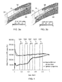
- Figures 3a and 3b represent local flow velocities around the blade 6 at the blade tip (i.e. at a section positioned at 99% of the blade span) at the onset of stall.
- Figure 3a shows the velocity profile with no casing treatment
- Figure 3b shows the velocity profile with a casing treatment as shown in Figure 2 .
- Figure 4 represents the pressure distribution around the blade 6, with the darker line representing the pressure distribution with no casing treatment, and the lighter line representing the pressure distribution with a casing treatment as shown in Figure 2 .
- Figures 3a and 3b show a high load region 28 towards the leading edge 20 of the blade 6, when the static pressure on the pressure side of the blade is high. This region typically extends over 0-10%AC from the leading edge 20.
- Figures 3a and 3b also show a shock 30 between subsonic and supersonic flow.
- the groove 16C is positioned at the foot of the shock 30, i.e. at the position where the shock meets the blade 6. It will be appreciated from Figure 3b that the presence of the grooves 16 causes disruption of the shock 30.
- the grooves 16 are shown extending axially away from the tip of the blade 6.
- the grooves can be considered to extend at an angle ⁇ of 90° from the axial direction, as shown in Figure 2 .
- a simulation was carried out in which the grooves 16 are inclined at different angles to the axial direction. It was found that increasing the angle ⁇ above 90° reduced the stall margin, while some ranges of angle less than 90° produced an improvement in stall margin. In particular, a groove angle ⁇ in the range 68 to 75° showed good results.
- the groove depths d are determined on the basis of the complex flow conditions at different positions along the chord of the blade 6.
- groove depths d are minimised for those grooves, such as 16A and 16B, where an optimised stall margin can be achieved with relatively shallow grooves.
- the effective tip clearance at these grooves remains relatively small, avoiding tip leakage losses, so enabling peak efficiency to be maintained.
- the groove depths d are thus influenced by their position along the blade chord, and take account of the complex flow physics which vary significantly between the leading edge 20 and the trailing edge 22.
- the deeper grooves are positioned at a significant distance a from the leading edge of the blade and the series of grooves 16 terminates at the groove 16E, significantly ahead of the trailing edge 22. This avoids the provision of grooves in regions where they make little or no contribution to the improvement in stall margin.
Landscapes
- Engineering & Computer Science (AREA)
- Mechanical Engineering (AREA)
- General Engineering & Computer Science (AREA)
- Structures Of Non-Positive Displacement Pumps (AREA)
Applications Claiming Priority (1)
| Application Number | Priority Date | Filing Date | Title |
|---|---|---|---|
| GB1101811.6A GB2487900B (en) | 2011-02-03 | 2011-02-03 | A turbomachine comprising an annular casing and a bladed rotor |
Publications (3)
| Publication Number | Publication Date |
|---|---|
| EP2484913A2 true EP2484913A2 (fr) | 2012-08-08 |
| EP2484913A3 EP2484913A3 (fr) | 2018-04-11 |
| EP2484913B1 EP2484913B1 (fr) | 2018-12-19 |
Family
ID=43825008
Family Applications (1)
| Application Number | Title | Priority Date | Filing Date |
|---|---|---|---|
| EP12152509.1A Not-in-force EP2484913B1 (fr) | 2011-02-03 | 2012-01-25 | Turbomachine comportant un boîtier annulaire et rotor à pales |
Country Status (3)
| Country | Link |
|---|---|
| US (1) | US9004859B2 (fr) |
| EP (1) | EP2484913B1 (fr) |
| GB (1) | GB2487900B (fr) |
Cited By (3)
| Publication number | Priority date | Publication date | Assignee | Title |
|---|---|---|---|---|
| FR2994718A1 (fr) * | 2012-08-27 | 2014-02-28 | Snecma | Carter a traitements de carter arasants |
| EP2990601A1 (fr) * | 2014-08-28 | 2016-03-02 | Honeywell International Inc. | Procédé pour améliorer la performance d'un moteur à turbine à gaz |
| EP3056740A3 (fr) * | 2015-02-10 | 2016-11-16 | United Technologies Corporation | Traitement de tubage à rainure circonférentielle optimisée pour compresseurs axiaux |
Families Citing this family (5)
| Publication number | Priority date | Publication date | Assignee | Title |
|---|---|---|---|---|
| WO2014158236A1 (fr) * | 2013-03-12 | 2014-10-02 | United Technologies Corporation | Stator en porte-à-faux comportant une caractéristique de déclenchement de tourbillon |
| US10465716B2 (en) * | 2014-08-08 | 2019-11-05 | Pratt & Whitney Canada Corp. | Compressor casing |
| US10487847B2 (en) | 2016-01-19 | 2019-11-26 | Pratt & Whitney Canada Corp. | Gas turbine engine blade casing |
| US10914318B2 (en) | 2019-01-10 | 2021-02-09 | General Electric Company | Engine casing treatment for reducing circumferentially variable distortion |
| US20230151825A1 (en) * | 2021-11-17 | 2023-05-18 | Pratt & Whitney Canada Corp. | Compressor shroud with swept grooves |
Citations (1)
| Publication number | Priority date | Publication date | Assignee | Title |
|---|---|---|---|---|
| EP1801361A1 (fr) | 2005-12-22 | 2007-06-27 | Rolls-Royce plc | Boîtier de ventilateur ou de compresseur |
Family Cites Families (10)
| Publication number | Priority date | Publication date | Assignee | Title |
|---|---|---|---|---|
| SU926365A1 (ru) * | 1980-05-12 | 1982-05-07 | Харьковский авиационный институт им.Н.Е.Жуковского | Осевой компрессор |
| JPS6318799Y2 (fr) * | 1980-12-02 | 1988-05-26 | ||
| FR2558900B1 (fr) * | 1984-02-01 | 1988-05-27 | Snecma | Dispositif d'etancheite peripherique d'aubage de compresseur axial |
| GB2245312B (en) * | 1984-06-19 | 1992-03-25 | Rolls Royce Plc | Axial flow compressor surge margin improvement |
| RU2034175C1 (ru) * | 1993-03-11 | 1995-04-30 | Центральный институт авиационного моторостроения им.П.И.Баранова | Турбокомпрессор |
| JP3816150B2 (ja) * | 1995-07-18 | 2006-08-30 | 株式会社荏原製作所 | 遠心流体機械 |
| US6234747B1 (en) * | 1999-11-15 | 2001-05-22 | General Electric Company | Rub resistant compressor stage |
| DE102008011644A1 (de) * | 2008-02-28 | 2009-09-03 | Rolls-Royce Deutschland Ltd & Co Kg | Gehäusestrukturierung für Axialverdichter im Nabenbereich |
| FR2929349B1 (fr) * | 2008-03-28 | 2010-04-16 | Snecma | Carter pour roue a aubes mobiles de turbomachine |
| US8337146B2 (en) * | 2009-06-03 | 2012-12-25 | Pratt & Whitney Canada Corp. | Rotor casing treatment with recessed baffles |
-
2011
- 2011-02-03 GB GB1101811.6A patent/GB2487900B/en not_active Expired - Fee Related
-
2012
- 2012-01-25 EP EP12152509.1A patent/EP2484913B1/fr not_active Not-in-force
- 2012-01-25 US US13/358,149 patent/US9004859B2/en not_active Expired - Fee Related
Patent Citations (1)
| Publication number | Priority date | Publication date | Assignee | Title |
|---|---|---|---|---|
| EP1801361A1 (fr) | 2005-12-22 | 2007-06-27 | Rolls-Royce plc | Boîtier de ventilateur ou de compresseur |
Cited By (5)
| Publication number | Priority date | Publication date | Assignee | Title |
|---|---|---|---|---|
| FR2994718A1 (fr) * | 2012-08-27 | 2014-02-28 | Snecma | Carter a traitements de carter arasants |
| EP2990601A1 (fr) * | 2014-08-28 | 2016-03-02 | Honeywell International Inc. | Procédé pour améliorer la performance d'un moteur à turbine à gaz |
| US10046424B2 (en) | 2014-08-28 | 2018-08-14 | Honeywell International Inc. | Rotors with stall margin and efficiency optimization and methods for improving gas turbine engine performance therewith |
| EP3056740A3 (fr) * | 2015-02-10 | 2016-11-16 | United Technologies Corporation | Traitement de tubage à rainure circonférentielle optimisée pour compresseurs axiaux |
| US10066640B2 (en) | 2015-02-10 | 2018-09-04 | United Technologies Corporation | Optimized circumferential groove casing treatment for axial compressors |
Also Published As
| Publication number | Publication date |
|---|---|
| GB201101811D0 (en) | 2011-03-16 |
| US20120201671A1 (en) | 2012-08-09 |
| GB2487900B (en) | 2013-02-06 |
| US9004859B2 (en) | 2015-04-14 |
| GB2487900A (en) | 2012-08-15 |
| EP2484913A3 (fr) | 2018-04-11 |
| EP2484913B1 (fr) | 2018-12-19 |
Similar Documents
| Publication | Publication Date | Title |
|---|---|---|
| EP2484913B1 (fr) | Turbomachine comportant un boîtier annulaire et rotor à pales | |
| US11098731B2 (en) | Grooved shroud casing treatment for high pressure compressor in a turbine engine | |
| US8684698B2 (en) | Compressor airfoil with tip dihedral | |
| US7726937B2 (en) | Turbine engine compressor vanes | |
| EP3183428B1 (fr) | Aube de compresseur | |
| US20160153465A1 (en) | Axial compressor endwall treatment for controlling leakage flow therein | |
| US10760424B2 (en) | Compressor rotor airfoil | |
| US10047620B2 (en) | Circumferentially varying axial compressor endwall treatment for controlling leakage flow therein | |
| US9885371B2 (en) | Row of aerofoil members | |
| US10539154B2 (en) | Compressor end-wall treatment having a bent profile | |
| CA2762785C (fr) | Composant de moteur a turbine a gaz a profil aerodynamique | |
| CN109477391B (zh) | 涡扇发动机及对应的操作方法 | |
| US10443607B2 (en) | Blade for an axial flow machine | |
| US10823194B2 (en) | Compressor end-wall treatment with multiple flow axes | |
| US20210372288A1 (en) | Compressor stator with leading edge fillet | |
| US20140234095A1 (en) | Aerofoil for axial-flow machine | |
| EP3186484B1 (fr) | Turbine à gaz | |
| EP3290637A1 (fr) | Pales de rotor en tandem avec éléments de refroidissement | |
| RU2727823C2 (ru) | Лопатка ротора турбомашины, диск с лопатками, ротор и турбомашина | |
| US20160369816A1 (en) | Tandem rotor blades with cooling features | |
| EP4332348A1 (fr) | Procede et appareil de traitement de paroi d'extremite | |
| US20240060429A1 (en) | Method and apparatus for endwall treatments | |
| US20200165968A1 (en) | Fan assembly having flow recirculation circuit with rotating airfoils | |
| CN113272520A (zh) | 具有高颤振裕度的最大厚度定律的涡轮机叶片 |
Legal Events
| Date | Code | Title | Description |
|---|---|---|---|
| PUAI | Public reference made under article 153(3) epc to a published international application that has entered the european phase |
Free format text: ORIGINAL CODE: 0009012 |
|
| AK | Designated contracting states |
Kind code of ref document: A2 Designated state(s): AL AT BE BG CH CY CZ DE DK EE ES FI FR GB GR HR HU IE IS IT LI LT LU LV MC MK MT NL NO PL PT RO RS SE SI SK SM TR |
|
| AX | Request for extension of the european patent |
Extension state: BA ME |
|
| RAP1 | Party data changed (applicant data changed or rights of an application transferred) |
Owner name: ROLLS-ROYCE PLC |
|
| REG | Reference to a national code |
Ref country code: DE Ref legal event code: R079 Ref document number: 602012054761 Country of ref document: DE Free format text: PREVIOUS MAIN CLASS: F04D0027020000 Ipc: F04D0029160000 |
|
| PUAL | Search report despatched |
Free format text: ORIGINAL CODE: 0009013 |
|
| AK | Designated contracting states |
Kind code of ref document: A3 Designated state(s): AL AT BE BG CH CY CZ DE DK EE ES FI FR GB GR HR HU IE IS IT LI LT LU LV MC MK MT NL NO PL PT RO RS SE SI SK SM TR |
|
| AX | Request for extension of the european patent |
Extension state: BA ME |
|
| RIC1 | Information provided on ipc code assigned before grant |
Ipc: F01D 11/08 20060101ALI20180306BHEP Ipc: F04D 29/68 20060101ALI20180306BHEP Ipc: F01D 25/24 20060101ALI20180306BHEP Ipc: F04D 29/16 20060101AFI20180306BHEP Ipc: F04D 29/52 20060101ALI20180306BHEP |
|
| STAA | Information on the status of an ep patent application or granted ep patent |
Free format text: STATUS: REQUEST FOR EXAMINATION WAS MADE |
|
| 17P | Request for examination filed |
Effective date: 20180801 |
|
| RBV | Designated contracting states (corrected) |
Designated state(s): AL AT BE BG CH CY CZ DE DK EE ES FI FR GB GR HR HU IE IS IT LI LT LU LV MC MK MT NL NO PL PT RO RS SE SI SK SM TR |
|
| GRAP | Despatch of communication of intention to grant a patent |
Free format text: ORIGINAL CODE: EPIDOSNIGR1 |
|
| STAA | Information on the status of an ep patent application or granted ep patent |
Free format text: STATUS: GRANT OF PATENT IS INTENDED |
|
| GRAS | Grant fee paid |
Free format text: ORIGINAL CODE: EPIDOSNIGR3 |
|
| INTG | Intention to grant announced |
Effective date: 20181015 |
|
| GRAA | (expected) grant |
Free format text: ORIGINAL CODE: 0009210 |
|
| STAA | Information on the status of an ep patent application or granted ep patent |
Free format text: STATUS: THE PATENT HAS BEEN GRANTED |
|
| AK | Designated contracting states |
Kind code of ref document: B1 Designated state(s): AL AT BE BG CH CY CZ DE DK EE ES FI FR GB GR HR HU IE IS IT LI LT LU LV MC MK MT NL NO PL PT RO RS SE SI SK SM TR |
|
| REG | Reference to a national code |
Ref country code: GB Ref legal event code: FG4D |
|
| REG | Reference to a national code |
Ref country code: CH Ref legal event code: EP |
|
| REG | Reference to a national code |
Ref country code: IE Ref legal event code: FG4D |
|
| REG | Reference to a national code |
Ref country code: DE Ref legal event code: R096 Ref document number: 602012054761 Country of ref document: DE |
|
| REG | Reference to a national code |
Ref country code: AT Ref legal event code: REF Ref document number: 1079031 Country of ref document: AT Kind code of ref document: T Effective date: 20190115 |
|
| REG | Reference to a national code |
Ref country code: NL Ref legal event code: MP Effective date: 20181219 |
|
| PG25 | Lapsed in a contracting state [announced via postgrant information from national office to epo] |
Ref country code: LT Free format text: LAPSE BECAUSE OF FAILURE TO SUBMIT A TRANSLATION OF THE DESCRIPTION OR TO PAY THE FEE WITHIN THE PRESCRIBED TIME-LIMIT Effective date: 20181219 Ref country code: HR Free format text: LAPSE BECAUSE OF FAILURE TO SUBMIT A TRANSLATION OF THE DESCRIPTION OR TO PAY THE FEE WITHIN THE PRESCRIBED TIME-LIMIT Effective date: 20181219 Ref country code: NO Free format text: LAPSE BECAUSE OF FAILURE TO SUBMIT A TRANSLATION OF THE DESCRIPTION OR TO PAY THE FEE WITHIN THE PRESCRIBED TIME-LIMIT Effective date: 20190319 Ref country code: BG Free format text: LAPSE BECAUSE OF FAILURE TO SUBMIT A TRANSLATION OF THE DESCRIPTION OR TO PAY THE FEE WITHIN THE PRESCRIBED TIME-LIMIT Effective date: 20190319 Ref country code: FI Free format text: LAPSE BECAUSE OF FAILURE TO SUBMIT A TRANSLATION OF THE DESCRIPTION OR TO PAY THE FEE WITHIN THE PRESCRIBED TIME-LIMIT Effective date: 20181219 Ref country code: LV Free format text: LAPSE BECAUSE OF FAILURE TO SUBMIT A TRANSLATION OF THE DESCRIPTION OR TO PAY THE FEE WITHIN THE PRESCRIBED TIME-LIMIT Effective date: 20181219 |
|
| REG | Reference to a national code |
Ref country code: LT Ref legal event code: MG4D |
|
| REG | Reference to a national code |
Ref country code: AT Ref legal event code: MK05 Ref document number: 1079031 Country of ref document: AT Kind code of ref document: T Effective date: 20181219 |
|
| PG25 | Lapsed in a contracting state [announced via postgrant information from national office to epo] |
Ref country code: RS Free format text: LAPSE BECAUSE OF FAILURE TO SUBMIT A TRANSLATION OF THE DESCRIPTION OR TO PAY THE FEE WITHIN THE PRESCRIBED TIME-LIMIT Effective date: 20181219 Ref country code: AL Free format text: LAPSE BECAUSE OF FAILURE TO SUBMIT A TRANSLATION OF THE DESCRIPTION OR TO PAY THE FEE WITHIN THE PRESCRIBED TIME-LIMIT Effective date: 20181219 Ref country code: GR Free format text: LAPSE BECAUSE OF FAILURE TO SUBMIT A TRANSLATION OF THE DESCRIPTION OR TO PAY THE FEE WITHIN THE PRESCRIBED TIME-LIMIT Effective date: 20190320 Ref country code: SE Free format text: LAPSE BECAUSE OF FAILURE TO SUBMIT A TRANSLATION OF THE DESCRIPTION OR TO PAY THE FEE WITHIN THE PRESCRIBED TIME-LIMIT Effective date: 20181219 |
|
| PG25 | Lapsed in a contracting state [announced via postgrant information from national office to epo] |
Ref country code: NL Free format text: LAPSE BECAUSE OF FAILURE TO SUBMIT A TRANSLATION OF THE DESCRIPTION OR TO PAY THE FEE WITHIN THE PRESCRIBED TIME-LIMIT Effective date: 20181219 |
|
| PG25 | Lapsed in a contracting state [announced via postgrant information from national office to epo] |
Ref country code: IT Free format text: LAPSE BECAUSE OF FAILURE TO SUBMIT A TRANSLATION OF THE DESCRIPTION OR TO PAY THE FEE WITHIN THE PRESCRIBED TIME-LIMIT Effective date: 20181219 Ref country code: ES Free format text: LAPSE BECAUSE OF FAILURE TO SUBMIT A TRANSLATION OF THE DESCRIPTION OR TO PAY THE FEE WITHIN THE PRESCRIBED TIME-LIMIT Effective date: 20181219 Ref country code: PT Free format text: LAPSE BECAUSE OF FAILURE TO SUBMIT A TRANSLATION OF THE DESCRIPTION OR TO PAY THE FEE WITHIN THE PRESCRIBED TIME-LIMIT Effective date: 20190419 Ref country code: PL Free format text: LAPSE BECAUSE OF FAILURE TO SUBMIT A TRANSLATION OF THE DESCRIPTION OR TO PAY THE FEE WITHIN THE PRESCRIBED TIME-LIMIT Effective date: 20181219 Ref country code: CZ Free format text: LAPSE BECAUSE OF FAILURE TO SUBMIT A TRANSLATION OF THE DESCRIPTION OR TO PAY THE FEE WITHIN THE PRESCRIBED TIME-LIMIT Effective date: 20181219 |
|
| PG25 | Lapsed in a contracting state [announced via postgrant information from national office to epo] |
Ref country code: SM Free format text: LAPSE BECAUSE OF FAILURE TO SUBMIT A TRANSLATION OF THE DESCRIPTION OR TO PAY THE FEE WITHIN THE PRESCRIBED TIME-LIMIT Effective date: 20181219 Ref country code: EE Free format text: LAPSE BECAUSE OF FAILURE TO SUBMIT A TRANSLATION OF THE DESCRIPTION OR TO PAY THE FEE WITHIN THE PRESCRIBED TIME-LIMIT Effective date: 20181219 Ref country code: RO Free format text: LAPSE BECAUSE OF FAILURE TO SUBMIT A TRANSLATION OF THE DESCRIPTION OR TO PAY THE FEE WITHIN THE PRESCRIBED TIME-LIMIT Effective date: 20181219 Ref country code: SK Free format text: LAPSE BECAUSE OF FAILURE TO SUBMIT A TRANSLATION OF THE DESCRIPTION OR TO PAY THE FEE WITHIN THE PRESCRIBED TIME-LIMIT Effective date: 20181219 Ref country code: IS Free format text: LAPSE BECAUSE OF FAILURE TO SUBMIT A TRANSLATION OF THE DESCRIPTION OR TO PAY THE FEE WITHIN THE PRESCRIBED TIME-LIMIT Effective date: 20190419 |
|
| REG | Reference to a national code |
Ref country code: CH Ref legal event code: PL |
|
| REG | Reference to a national code |
Ref country code: DE Ref legal event code: R097 Ref document number: 602012054761 Country of ref document: DE |
|
| PG25 | Lapsed in a contracting state [announced via postgrant information from national office to epo] |
Ref country code: LU Free format text: LAPSE BECAUSE OF NON-PAYMENT OF DUE FEES Effective date: 20190125 |
|
| REG | Reference to a national code |
Ref country code: BE Ref legal event code: MM Effective date: 20190131 |
|
| PLBE | No opposition filed within time limit |
Free format text: ORIGINAL CODE: 0009261 |
|
| STAA | Information on the status of an ep patent application or granted ep patent |
Free format text: STATUS: NO OPPOSITION FILED WITHIN TIME LIMIT |
|
| REG | Reference to a national code |
Ref country code: IE Ref legal event code: MM4A |
|
| PG25 | Lapsed in a contracting state [announced via postgrant information from national office to epo] |
Ref country code: DK Free format text: LAPSE BECAUSE OF FAILURE TO SUBMIT A TRANSLATION OF THE DESCRIPTION OR TO PAY THE FEE WITHIN THE PRESCRIBED TIME-LIMIT Effective date: 20181219 Ref country code: AT Free format text: LAPSE BECAUSE OF FAILURE TO SUBMIT A TRANSLATION OF THE DESCRIPTION OR TO PAY THE FEE WITHIN THE PRESCRIBED TIME-LIMIT Effective date: 20181219 Ref country code: MC Free format text: LAPSE BECAUSE OF FAILURE TO SUBMIT A TRANSLATION OF THE DESCRIPTION OR TO PAY THE FEE WITHIN THE PRESCRIBED TIME-LIMIT Effective date: 20181219 |
|
| 26N | No opposition filed |
Effective date: 20190920 |
|
| PG25 | Lapsed in a contracting state [announced via postgrant information from national office to epo] |
Ref country code: BE Free format text: LAPSE BECAUSE OF NON-PAYMENT OF DUE FEES Effective date: 20190131 |
|
| PG25 | Lapsed in a contracting state [announced via postgrant information from national office to epo] |
Ref country code: LI Free format text: LAPSE BECAUSE OF NON-PAYMENT OF DUE FEES Effective date: 20190131 Ref country code: CH Free format text: LAPSE BECAUSE OF NON-PAYMENT OF DUE FEES Effective date: 20190131 |
|
| PG25 | Lapsed in a contracting state [announced via postgrant information from national office to epo] |
Ref country code: IE Free format text: LAPSE BECAUSE OF NON-PAYMENT OF DUE FEES Effective date: 20190125 |
|
| PG25 | Lapsed in a contracting state [announced via postgrant information from national office to epo] |
Ref country code: SI Free format text: LAPSE BECAUSE OF FAILURE TO SUBMIT A TRANSLATION OF THE DESCRIPTION OR TO PAY THE FEE WITHIN THE PRESCRIBED TIME-LIMIT Effective date: 20181219 |
|
| PG25 | Lapsed in a contracting state [announced via postgrant information from national office to epo] |
Ref country code: TR Free format text: LAPSE BECAUSE OF FAILURE TO SUBMIT A TRANSLATION OF THE DESCRIPTION OR TO PAY THE FEE WITHIN THE PRESCRIBED TIME-LIMIT Effective date: 20181219 |
|
| PGFP | Annual fee paid to national office [announced via postgrant information from national office to epo] |
Ref country code: GB Payment date: 20200127 Year of fee payment: 9 Ref country code: DE Payment date: 20200129 Year of fee payment: 9 |
|
| PG25 | Lapsed in a contracting state [announced via postgrant information from national office to epo] |
Ref country code: MT Free format text: LAPSE BECAUSE OF NON-PAYMENT OF DUE FEES Effective date: 20190125 |
|
| PGFP | Annual fee paid to national office [announced via postgrant information from national office to epo] |
Ref country code: FR Payment date: 20200127 Year of fee payment: 9 |
|
| PG25 | Lapsed in a contracting state [announced via postgrant information from national office to epo] |
Ref country code: CY Free format text: LAPSE BECAUSE OF FAILURE TO SUBMIT A TRANSLATION OF THE DESCRIPTION OR TO PAY THE FEE WITHIN THE PRESCRIBED TIME-LIMIT Effective date: 20181219 |
|
| PG25 | Lapsed in a contracting state [announced via postgrant information from national office to epo] |
Ref country code: HU Free format text: LAPSE BECAUSE OF FAILURE TO SUBMIT A TRANSLATION OF THE DESCRIPTION OR TO PAY THE FEE WITHIN THE PRESCRIBED TIME-LIMIT; INVALID AB INITIO Effective date: 20120125 |
|
| REG | Reference to a national code |
Ref country code: DE Ref legal event code: R119 Ref document number: 602012054761 Country of ref document: DE |
|
| GBPC | Gb: european patent ceased through non-payment of renewal fee |
Effective date: 20210125 |
|
| PG25 | Lapsed in a contracting state [announced via postgrant information from national office to epo] |
Ref country code: FR Free format text: LAPSE BECAUSE OF NON-PAYMENT OF DUE FEES Effective date: 20210131 |
|
| PG25 | Lapsed in a contracting state [announced via postgrant information from national office to epo] |
Ref country code: DE Free format text: LAPSE BECAUSE OF NON-PAYMENT OF DUE FEES Effective date: 20210803 Ref country code: GB Free format text: LAPSE BECAUSE OF NON-PAYMENT OF DUE FEES Effective date: 20210125 |
|
| PG25 | Lapsed in a contracting state [announced via postgrant information from national office to epo] |
Ref country code: MK Free format text: LAPSE BECAUSE OF FAILURE TO SUBMIT A TRANSLATION OF THE DESCRIPTION OR TO PAY THE FEE WITHIN THE PRESCRIBED TIME-LIMIT Effective date: 20181219 |