EP2484393A1 - Pre-filled syringe - Google Patents
Pre-filled syringe Download PDFInfo
- Publication number
- EP2484393A1 EP2484393A1 EP10820637A EP10820637A EP2484393A1 EP 2484393 A1 EP2484393 A1 EP 2484393A1 EP 10820637 A EP10820637 A EP 10820637A EP 10820637 A EP10820637 A EP 10820637A EP 2484393 A1 EP2484393 A1 EP 2484393A1
- Authority
- EP
- European Patent Office
- Prior art keywords
- plunger
- mounting member
- spiral
- distal
- rib
- Prior art date
- Legal status (The legal status is an assumption and is not a legal conclusion. Google has not performed a legal analysis and makes no representation as to the accuracy of the status listed.)
- Granted
Links
Images









Classifications
-
- A—HUMAN NECESSITIES
- A61—MEDICAL OR VETERINARY SCIENCE; HYGIENE
- A61M—DEVICES FOR INTRODUCING MEDIA INTO, OR ONTO, THE BODY; DEVICES FOR TRANSDUCING BODY MEDIA OR FOR TAKING MEDIA FROM THE BODY; DEVICES FOR PRODUCING OR ENDING SLEEP OR STUPOR
- A61M5/00—Devices for bringing media into the body in a subcutaneous, intra-vascular or intramuscular way; Accessories therefor, e.g. filling or cleaning devices, arm-rests
- A61M5/178—Syringes
- A61M5/31—Details
- A61M5/315—Pistons; Piston-rods; Guiding, blocking or restricting the movement of the rod or piston; Appliances on the rod for facilitating dosing ; Dosing mechanisms
- A61M5/31511—Piston or piston-rod constructions, e.g. connection of piston with piston-rod
- A61M5/31515—Connection of piston with piston rod
-
- A—HUMAN NECESSITIES
- A61—MEDICAL OR VETERINARY SCIENCE; HYGIENE
- A61M—DEVICES FOR INTRODUCING MEDIA INTO, OR ONTO, THE BODY; DEVICES FOR TRANSDUCING BODY MEDIA OR FOR TAKING MEDIA FROM THE BODY; DEVICES FOR PRODUCING OR ENDING SLEEP OR STUPOR
- A61M5/00—Devices for bringing media into the body in a subcutaneous, intra-vascular or intramuscular way; Accessories therefor, e.g. filling or cleaning devices, arm-rests
- A61M5/14—Infusion devices, e.g. infusing by gravity; Blood infusion; Accessories therefor
- A61M5/142—Pressure infusion, e.g. using pumps
- A61M5/145—Pressure infusion, e.g. using pumps using pressurised reservoirs, e.g. pressurised by means of pistons
- A61M5/1452—Pressure infusion, e.g. using pumps using pressurised reservoirs, e.g. pressurised by means of pistons pressurised by means of pistons
-
- A—HUMAN NECESSITIES
- A61—MEDICAL OR VETERINARY SCIENCE; HYGIENE
- A61M—DEVICES FOR INTRODUCING MEDIA INTO, OR ONTO, THE BODY; DEVICES FOR TRANSDUCING BODY MEDIA OR FOR TAKING MEDIA FROM THE BODY; DEVICES FOR PRODUCING OR ENDING SLEEP OR STUPOR
- A61M5/00—Devices for bringing media into the body in a subcutaneous, intra-vascular or intramuscular way; Accessories therefor, e.g. filling or cleaning devices, arm-rests
- A61M5/14—Infusion devices, e.g. infusing by gravity; Blood infusion; Accessories therefor
- A61M5/142—Pressure infusion, e.g. using pumps
- A61M5/145—Pressure infusion, e.g. using pumps using pressurised reservoirs, e.g. pressurised by means of pistons
- A61M5/1452—Pressure infusion, e.g. using pumps using pressurised reservoirs, e.g. pressurised by means of pistons pressurised by means of pistons
- A61M5/1458—Means for capture of the plunger flange
Definitions
- the present invention relates to a prefilled syringe in which a medicine is filled in advance.
- a vacuum plugging In inserting the gasket into the prefilled syringe, generally used is a method so-called a vacuum plugging in which after a medicine is filled inside the outer cylinder whose opening formed at its distal end is sealed, the gasket is disposed at an opening of the outer cylinder under a pressure-decreased atmosphere (under a vacuum atmosphere), and thereafter a normal pressure state is generated to insert the gasket into the outer cylinder.
- a vacuum plugging work is performed without mounting the plunger on the gasket. Therefore generally the prefilled syringe necessitates a plunger-mounting work to be performed subsequently.
- the prefilled syringe has a mounting mechanism of mounting the plunger on the gasket by screwing a male screw portion formed on the plunger on a female screw portion formed on the gasket.
- Japanese Patent Application Laid-Open No. 2002-272843 (patent document 1), Japanese Patent Application Laid-Open No. 2009-142508 (patent document 2), International Publication WO01-97885 (patent document 3), and Japanese Patent Application Laid-Open No. 2007-202822 (patent document 4) are listed.
- the patent documents 1 through 3 are proposed by the present applicant.
- Syringes in which the gasket is constructed of a gasket body and a plunger-mounting member are proposed.
- Japanese Utility Model Application Laid-Open No. 6-39005 (patent document 5), Japanese Patent Application Laid-Open No. 2007-44159 (patent document 6), Japanese Patent Application Laid-Open No. 2008-307237 (patent document 7), and Japanese Patent No. 3665646 (patent document 8, WO95-30444 ) are listed.
- a syringe 1 of the patent document 1 Japanese Patent Application Laid-Open No. 2002-272843 ) has an outer cylinder 2, a gasket 3 capable of sliding inside the outer cylinder 2, and a plunger 4, having the function of performing the operation of moving the gasket 3, which is inserted into the outer cylinder 2 from the opening formed at the proximal end thereof.
- the liquid 7 is liquid-tightly accommodated in advance inside the space surrounded with the outer cylinder 2 and the gasket 3.
- the flange 44 is formed at the head part 43 formed at the distal portion of the plunger 4.
- the gasket 3 has the hollow part 33.
- the screw thread 34 is formed on the inner surface of the proximal side of the hollow part 33.
- the space 35 for accommodating the flange 44 is formed at a portion located distally from the screw thread 34.
- the flange 44 which has entered the space 35 across the screw thread 34 engages the space 35 in a loosely engage state.
- the flange 44 formed at the head part 43 of the distal portion of the plunger 4 is not screwlike.
- the syringe 10 of the patent document 2 has the gasket 3, the outer cylinder 2, and the plunger 4.
- the plunger 4 has the spiral rib 44 formed on the outer surface of the head part 42.
- the gasket 3 has the spiral screwing part 33 which is to screw the spiral rib 44, the annular rib 34, for preventing the separation of the plunger from the gasket, which is located at a position in the vicinity of the spiral screwing part 33 and distal therefrom, and the accommodation part 32 for accommodating the portion where the spiral rib 44 of the head part 42 of the plunger is formed.
- the annular rib 34 has the rib-absent portion 35 for guiding the spiral rib 44 which has reached the annular rib owing to the progress of the screwing between the spiral rib 44 of the plunger and the spiral screwing part 33 of the gasket to the accommodation part.
- This syringe is effective for preventing the separation of the plunger from the gasket. But in dependence on a manner of the work of mounting the plunger on the gasket, defective mounting of the plunger on the gasket sometimes occurs.
- the head part (coupling portion) 43 to be inserted into the hollow part 33 of the gasket 3 and coupled to the gasket 3 is formed.
- a male screw 51 is formed on the outer circumferential surface of the head part 43.
- the female screw 52 on which the male screw 51 can be screwed is formed on the inner circumferential surface of the hollow part 33 of the gasket 3.
- the head part 43 has the elastic piece 61 located at a position distal from the male screw 51 and the projected portions 62, projectingly formed toward the outer circumference thereof, which are located in the vicinity of the end portions of elastic pieces 61.
- the ring-shaped engaging projected part 63 is formed on the inner circumferential surface of the hollow part 33 of the gasket 3 at a position distal from the female screw 52. In this syringe, the plunger is mounted on the gasket by rotating the plunger.
- the plunger used for the syringe of the patent document 4 includes the plunger rod 22 and the gasket 21.
- the gasket 21 has the inner space whose distal end is closed and has an opening 212, having a smaller diameter than that of the inner space, which is formed at the proximal end thereof.
- the male screw-shaped projected part 223 is formed at the distal end of the plunger rod 22. When the projected part 223 enters the inner space across the opening 212, the gasket 21 and the plunger rod 22 engage each other in a free fit-on state.
- the "opening having a smaller diameter" of the syringe is "not screwlike", and necessarily has the function of preventing the plunger from dropping when the plunger is rotated reversely and in addition preventing the plunger from dropping when the plunger is pulled toward the proximal end of the syringe. Therefore the "opening having a smaller diameter” is required to have a high strength.
- the convexity screws the projected portion 223 with the convexity being twisted.
- the circularity of the peripheral side surface of the gasket becomes low and there is a possibility that a liquid may leak.
- the reinforcing material 30 made of synthetic resin is fitted on the inner chamber portion of the plunger 20 closely fitted in the syringe 2 serving as a container.
- the reinforcing material 30 reinforces the peripheral wall portion 23 forming the inner chamber portion of the plunger 20.
- the plunger rod 10 is removably mounted on the reinforcing material 30.
- the insertion portion 16 of the plunger rod 10 is inserted into the insertion hole 34 (see Fig. 2 of the specification of the patent document 5) of the cover portion 32 of the reinforcing material 30.
- the plunger rod 10 is rotated to fit the opposed side 18 of the window spline 17 of the insertion portion 16 of the plunger rod 10 on the fit-on groove 36 (see Fig. 3 of the specification of the patent document 5) of the back surface 35 of the cover portion 32 of the reinforcing material 30.
- the syringe 1 of the patent document 6 Japanese Patent Application Laid-Open No. 2007-44159 ) has the outer cylinder 2, the gasket 3 capable of sliding inside the outer cylinder 2, and the plunger 4 for performing the operation of moving the gasket 3.
- the gasket 3 and the plunger 4 are coupled to each other by a coupling mechanism.
- the plunger 4 is composed of the upper plunger 41 and the lower plunger 42 fitted thereon. At the time of fitting the lower plunger 41 on the upper plunger 42, the convex portion 422 formed on the lower plunger 42 is inserted into the concave portion 412 formed on the upper plunger 41.
- a medicinal solution is filled therein and the gasket is plugged into the outer cylinder.
- the prefilled syringe includes the coupler which screws the proximal end of the gasket, the bottom rod coupled to the coupler at its proximal end, the stopper formed on the coupler, and the engaging part, formed on the bottom rod, which engages the stopper owing to the rotation of the bottom rod in the screwing direction.
- the stopper contacts the engaging portion in the direction opposite to the screwing direction, the stopper elastically deforms and does not engage the engaging part.
- the syringe of the patent document 8 Japanese Patent No. 3665646 : WO95-30444 shown in Figs. 1 through 6 of the specification thereof has the barrel, the plunger, and the plunger rod.
- the plunger By driving the plunger rod, the plunger generates an axial tensile force.
- the diameter of the plunger decreases.
- the plunger rod has the rod member and the connection member for the plunger.
- the rod member is axially slidable with respect to the connection member.
- the plunger insertion part 68 has the female screw 69 which engages the male screw 71 of the plunger rod 50.
- the plunger rod 50 has the male screw 71 so designed that the male screw 71 engages the female screw 69 of the plunger insertion part 68.
- This syringe also necessitates a rotation operation to be performed to mount the plunger.
- the syringe of the embodiment shown in Figs. 7 through 18 of the specification of the patent document 8 has the semicircular plunger rod distal end 164 having the convex surface projected toward the plunger.
- a prefilled syringe of this invention comprises a prefilled syringe body including an outer cylinder, a gasket slidably accommodated inside said outer cylinder, a sealing member for sealing an opening formed at a distal end of said outer cylinder, and a medicine accommodated inside a medicine accommodation part formed inside said outer cylinder; and a plunger which can be mounted on said gasket and is not mounted thereon;
- said gasket is composed of a gasket body which is a tubular body whose distal end is closed and proximal end is open and has a lumen part extended from an opening formed at said proximal end thereof to a distal side thereof and a plunger-mounting member mounted on said gasket body;
- said plunger-mounting member has a body part which is a tubular body having a hollow part penetrating therethrough from one end thereof to other end thereof and has a distal side flange part capable of
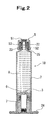
- a prefilled syringe 1 of the present invention has a prefilled syringe body 10 including an outer cylinder 2, a gasket 3 slidably accommodated inside the outer cylinder 2, a sealing member 5 for sealing an opening formed at a distal end of the outer cylinder 2, and a medicine 8 accommodated inside a medicine accommodation part formed inside the outer cylinder 2; and a plunger 4 which can be mounted on the gasket 3 and is not mounted thereon.
- the gasket 3 is composed of a gasket body 6 which is a tubular body whose distal end is closed and proximal end is open and which has a lumen part 60 extended from an opening formed at the proximal end thereof to a distal side thereof and a plunger-mounting member 7 mounted on the gasket body 6.
- the plunger-mounting member 7 has a body part 70 which is a tubular body having a hollow part penetrating therethrough from one end thereof to the other end thereof and has a distal side flange part 72 capable of pressing a proximal end surface of the gasket body 6 at a distal side thereof, a distal part 71 which is projected distally from the body part 70 and can be accommodated inside the lumen part 60 of the gasket body 6, spiral ribs 74, 75 formed on an outer surface of the distal part 71, a proximal side flange part 73 formed at a proximal side of the body part 70, and a plunger-mounting part, formed inside a proximal portion of the body part 70, on which the plunger 4 is to be mounted.
- the gasket body 6 has a spiral screwing part 63 (63a, 63b), formed on an inner surface of the lumen part 60, which is to screw the spiral ribs 74, 75 of the plunger-mounting member 7 and an accommodation part 62, disposed distally from the spiral screwing part 63 (63a, 63b) of the lumen part 60, for accommodating a portion of the distal part 71 of the plunger-mounting member 7 where the spiral ribs 74, 75 are formed.
- the plunger 4 has a pressing part 48 capable of pressing a proximal end surface of the proximal side flange part 73 of the plunger-mounting member 7 in mounting the plunger 4 on the gasket 3 (specifically, in mounting the plunger 4 on the plunger-mounting member 7 of the gasket 3) and a mounting distal part 40, projected distally beyond the pressing part 48, which is capable of entering the plunger-mounting part of the plunger-mounting member 7.
- the plunger-mounting part of the plunger-mounting member 7 has a spiral concave portion 79 and an engaging rib 76 located at a position in the vicinity of the spiral concave portion 79 and distal therefrom.
- the mounting distal part 40 of the plunger 4 has a spiral projected portion 42 (42a, 42b) capable of screwing the spiral concave portion 79 of the plunger-mounting member 7 and an engaging portion 41, located at a position in the vicinity of the spiral projected portion 42 and distal therefrom, which engages the engaging rib 76 of the plunger-mounting member 7.
- the plunger-mounting member 7 is mounted on the gasket body 6 in a state that the spiral ribs 74, 75 are received in the accommodation part 62 and a distal end of the plunger-mounting member 7 does not contact an inner surface of the gasket body 6.
- the mounting distal part 40 of the plunger 4 does not contact the inner surface of the gasket body 6.
- the prefilled syringe 1 of the present invention is composed of the prefilled syringe body 10 and the plunger 4 which can be mounted on the prefilled syringe body 10 (gasket 3) and is not mounted thereon normally.
- the prefilled syringe body 10 has the outer cylinder 2, the sealing member 5 for sealing the opening formed at the distal end of the outer cylinder 2, the gasket 3 slidably accommodated inside the outer cylinder 2, and the medicine 8 accommodated inside the medicine accommodation part formed inside the outer cylinder 2.
- the gasket 3 is composed of the gasket body 6 and the plunger-mounting member 7 mounted thereon. As shown in Figs.
- the gasket body 6 is the tubular body having the closed distal end and the lumen part 60 extended from the opening formed at the proximal end of the gasket body 6 toward the distal side thereof.
- the gasket body 6 has a tapered part 61 the diameter of which taperingly decreases toward the distal end thereof.
- the gasket body 6 has a distal side annular rib 68 formed at a distal side of an outer surface thereof and a proximal side annular rib 69 formed at a proximal side of the outer surface thereof.
- the gasket body 6 has the lumen part 60 having the function of mounting the plunger-mounting member 7 thereon.
- the lumen part 60 has on its inner surface the spiral screwing part 63 which is to screw the spiral ribs 74, 75 of the plunger-mounting member 7 and the accommodation part 62, disposed distally from the spiral screwing part 63, for accommodating the portion of the distal part 71 of the plunger-mounting member 7 where the spiral ribs 74, 75 are formed.
- the gasket body 6 has an annular projected part 64, for preventing the removal of the plunger-mounting member 7 from the gasket body 6, located at a position in the vicinity of the spiral screwing part 63 and distal therefrom.
- the annular projected part 64 has a guide portion 65 for guiding the spiral ribs 74, 75 formed on the distal part 71 of the plunger-mounting member 7 to the accommodation part 62, when the spiral ribs 74, 75 reach the annular projected part 64 owing to the progress of screwing between the spiral ribs 74, 75 and the spiral screwing part 63 of the gasket body 6.
- the guide portion 65 is formed of a rib-absent portion.
- the guide portion does not necessarily have to be formed of the rib-absent portion, but may be formed of a concave portion, a thin portion or the like.
- the entire annular projected part 64 may be formed frailly.
- the accommodation part 62 is disposed distally from the annular projected part 64.
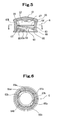
- the spiral screwing part 63 has a start point 63a located at a position in the vicinity of the opening of the lumen part 60, is extended toward the distal side of the gasket body 6 by a predetermined length, and has a termination point 63b located at a position in the vicinity of the rib-absent portion 65 of the annular projected part 64.
- the spiral screwing part 63 is composed of two lines (two pieces) so that the spiral screwing part 63 corresponds to the spiral ribs 74, 75 formed on the distal part 71 of the plunger-mounting member 7. To form the spiral screwing part 63 of the two lines (two pieces), as shown in Figs.
- the gasket body 6 of this embodiment has two lines of the spiral projections 66a, 66b.
- the spiral screwing part (spiral projection) may be composed of only one line (one piece).
- the spiral screwing part 63 is a groove-like part formed between the spiral projections 66 projected from the inner wall surface of the lumen part 60 of the gasket body 6.
- the spiral screwing part 63 is capable of screwing the spiral ribs 74, 75 of the plunger-mounting member 7 and guiding the spiral ribs 74, 75 toward the distal side of the gasket body 6.
- the spiral projection 66 has a start point located at a position in the vicinity of the opening of the lumen part 60, is extended toward the distal side of the gasket body 6 by the predetermined length, and has a termination point at a position slightly across the rib-absent portion 65 of the annular projected part 64.
- the gasket body 6 has the annular projected part 64, for preventing the removal of the plunger-mounting member 7 from the gasket body 6, formed on the inner surface of a portion located at a position in the vicinity of the spiral screwing part 63 and distal therefrom.
- the annular projected part 64 is extended almost orthogonally to the axis thereof.
- the annular projected part 64 may be a little oblique to the orthogonal state.
- the gasket body 6 has the accommodation part 62, disposed distally from the annular projected part 64, for accommodating the portion of the distal part 71 of the plunger-mounting member 7 where the spiral ribs 74, 75 are formed.
- the annular projected part 64 has the guide portion 65 for guiding the spiral ribs 74, 75 formed on the distal part 71 of the plunger-mounting member 7 to the accommodation part 62, when the spiral ribs 74, 75 reaches the annular projected part 64 owing to the progress of the screwing between the spiral ribs 74, 75 and the spiral screwing part 63 of the gasket body 6.
- two lines of the spiral screwing parts 63 are formed in correspondence to the two lines of the spiral ribs 74, 75. As shown in Fig.
- the rib-absent portion of the annular projected part 64 is formed at two positions substantially opposed to each other so that the rib-absent portion of the annular projected part 64 corresponds to the spiral screwing part 63 composed of the two lines.
- the gasket body 6 has two separated annular projected parts 64a, 64b and two rib-absent portions 65a, 65b positioned between the annular projected parts 64a and 64b.
- a rib of the annular projected part 64 (64a, 64b) becomes gradually smaller toward the rib-absent portion 65 (65a, 65b).
- the rib may become gradually smaller in its width or height or gradually smaller in its width and height toward the guide portion 65 (65a, 65b).
- the above-described construction allows the spiral ribs 74, 75 of the plunger-mounting member 7 to easily pass through the annular projected part 64, in other words, to easily enter the accommodation part 62.
- the rib of the rib-absent portion does not necessarily have to be completely absent, but may be absent to such an extent that the rib-absent portion has the function of guiding the spiral ribs 74, 75 of the plunger-mounting member 7 to the accommodation part 62.
- the width of the spiral screwing part 63 in other words, the distance between the spiral projection 66 and the annular projected part 64 becomes narrower toward the rib-absent portion 65 (also toward the termination point 63b of the spiral screwing part 63). Therefore the spiral ribs 74, 75 of the plunger-mounting member 7 can be securely guided to the rib-absent portion 65 of the annular projected part 64. It is preferable that the projected height of the spiral projection 66 for forming the spiral screwing part 63 of the gasket body 6 is higher than that of the annular projected part 64.
- the height of the annular projected part 64 is different according to the size of the gasket body 6, the height thereof is favorably 1.0 to 3.0mm and especially favorably 1.5 to 2.5mm.
- the width of the rib-absent portion 65 of the annular projected part 64 (the width of the rib-absent portion 65 in the circumferential direction of the gasket) is favorably 0.5 to 3.0mm and especially favorably 0.5 to 1.5mm.
- the gasket body 6 has a convex portion 67 projected from a central portion of the inner surface of the distal portion thereof toward the proximal side thereof.
- the convex portion 67 may be so constructed that it contacts the distal end 79 of the distal part 71 of the plunger-mounting member 7, when the distal portion of the gasket body 6 deforms toward its proximal side. It is preferable that the convex portion 67 is approximately semispherical. Generally the diameter of the gasket body 6 is 5 to 30mm, and the whole length thereof is 5 to 30mm.
- constituent materials of the gasket body 6 known materials conventionally used for the gasket can be used.
- rubber elastomer, polyolefin resin, fluororesin, and polyester resin are listed.
- the rubber natural rubber, isoprene rubber, butyl rubber, chloroprene rubber, nitrile-butadiene rubber, styrene-butadiene rubber, and silicone rubber are favorable. It is especially favorable to vulcanize the above-described rubbers.
- polyvinyl chloride elastomer polyolefin elastomer, styrene elastomer, polyester elastomer, polyamide elastomer, polyurethane elastomer, and mixtures of these elastomers are favorable.
- the styrene -butadiene rubber, the butyl rubber, and the styrene elastomer are preferable because these materials have suitable hardnesses and elastic properties and various sterilization methods such as y ray sterilization, electron beam sterilization, and high-pressure steam sterilization can be adopted therefor.
- the front side of the gasket body 6 may be coated with a low medicine-absorbable substance or the like.
- materials of a low medicine-absorbable layer known materials which are conventionally used for a laminate gasket can be used.
- materials of the low medicine-absorbable layer polyolefin resin, fluororesin, and polyester resin are listed. Specifically, as the polyolefin resin, polypropylene, ultra-high-molecular-weight polyethylene, poly (4-methylpentene-1), and cyclic polyolefin are preferable.
- a tetrafluoroethylene-perfluoroethoxyethylene copolymer polytetrafluoroethylene, a tetrafluoroethylene/perfluoroalkyl vinyl ether copolymer, a tetrafluoroethylene/hexafluoropropylene copolymer are preferable.
- a lubricant may be applied to the outer surface of the gasket body 6 and to at least the surface of each of the distal side annular rib 68 and the proximal side annular rib 69.
- the lubricant may be applied to the inner surface of the outer cylinder.
- silicone oil is suitable. By forming a silicone resin layer formed by solidifying the silicone resin on the surface of the gasket body, it is possible to eliminate the need for the use of the lubricant such as the silicone oil.
- the plunger-mounting member 7 is a tubular body, having a predetermined length, which has a hollow part penetrating therethrough from one end thereof to the other end thereof.
- the plunger-mounting member 7 has the body part 70, the distal part 71 which is projected distally from the body part 70 and can be accommodated inside the lumen part 60 of the gasket body 6, and the plunger-mounting part, formed inside the proximal portion of the body part 70, on which the plunger 4 is to be mounted.
- the body part 70 is the tubular body which has a predetermined length and the plunger-mounting part at its proximal portion.
- the tubular body part 70 having the predetermined length has a plurality of side plate portions 81 axially extended on its side surface.
- the body part 70 has the disk-shaped distal side flange part 72 capable of pressing the proximal end surface of the gasket body 6 at the distal end thereof.
- the body part 70 has the disk-shaped proximal side flange part 73 capable of contacting the pressing part 48 of the plunger 4 at the proximal end thereof.
- a plurality of the side plate portions 81 connects the distal side flange part 72 and the proximal side flange part 73 to each other and reinforces both flange parts 72 and 73.
- the outer edge of the distal side flange part 72 is almost circular.
- the outer diameter of the distal side flange part 72 is set a little smaller than that of the proximal end of the gasket body 6.
- the peripheral portion of the distal side flange part 72 at its distal end is formed as a flat surface and contacts and is capable of pressing the proximal end surface of the gasket body 6. In this embodiment, as shown in Figs.
- the proximal side flange part 73 has a flat plate portion and a collar portion having a predetermined length extended from the flat plate portion toward the proximal end of the plunger-mounting member 7.
- the proximal side flange part 73 has an outer collar 77 and an inner collar 78 both extended a little from the flat plate portion toward the proximal end of the plunger-mounting member 7.
- the outer collar 77 and the inner collar 78 are concentrically formed.
- the distal end (free end) of the outer collar 77 and that of the inner collar 78 are flatly formed.
- the distal end (free end) of the inner collar 78 is projected by a small amount beyond the distal end (free end) of the outer collar 77.
- the distal part 71 projected from the body part 70 is a cylindrical part which has an almost equal outer diameter and a predetermined length.
- the distal part 71 is formed shorter than the body part 70.
- the distal part 71 is projected distally from the vicinity of the center of the distal side flange part 72 of the body part 70.
- the distal part 71 does not contact the inner surface of the distal portion of the gasket body 6.
- the spiral ribs 74, 75 are formed on the outer surface of the distal portion of the distal part 71 of the plunger-mounting member 7. As shown in Figs.
- each of the spiral ribs 74, 75 has a start point located at a position in the vicinity of the distal end of the distal part 71 of the plunger-mounting member 7 and is extended toward the proximal side of the distal part 71 by a predetermined length.
- the plunger-mounting member 7 has a plurality of the spiral ribs (specifically, two lines), the spiral rib may be composed of only one line (one piece).
- the height of the annular projected part 64 of the gasket body 6 and that of the spiral rib of the plunger-mounting member 7 are set as described below:
- the height of the annular projected part 64 of the gasket body is favorably 1.0 to 3.0mm and more favorably 1.5 to 2.5mm.
- the height of the spiral rib of the plunger-mounting member 7 is favorably 2.5 to 3.2mm, more favorably 2.8 to 3.1mm, and most favorably 2.95 to 3.05mm.
- the width of a contact portion of the annular projected part and the spiral rib are favorably 0.5 to 2.5mm and especially favorably 1.0 to 2.3mm.
- the inner diameter of the annular projected part 64 of the gasket body 6 is favorably 16.0 to 20.0mm and especially favorably 17.0 to 19.0mm.
- the outer diameter of the spiral rib of the plunger-mounting member 7 is favorably 19.0 to 22.0mm and especially favorably 20.0 to 21.0mm.
- the plunger-mounting part for accommodating the mounting distal part 40 of the plunger 4 to be described later therein and mounting the mounting distal part 40 thereon is formed on the inner surface of the hollow part of plunger-mounting member 7.
- the plunger-mounting part has the spiral concave portion 79 on which the spiral projected portion 42 (42a, 42b) of the mounting distal part 40 is to screw and the engaging rib 76, located at a position in the vicinity of the spiral concave portion 79 and distal therefrom, which is to engage the engaging portion 41 of the mounting distal part 40.
- the plunger-mounting member 7 has a large-diameter opening 84 at its proximal end.
- the spiral concave portion 79 is formed on the inner surface of a lumen part having a smaller diameter than the large-diameter opening 84.
- the spiral concave portion 79 has a start point at a position a little distal from the opening formed at the proximal end of the plunger-mounting member 7 and is extended toward the distal side of the plunger-mounting member 7 by a predetermined length.
- the plunger-mounting part has two lines (two pieces) of the spiral concave portion 79. Although it is preferable that the plunger-mounting part has a plurality of (specifically, two lines) the spiral concave portions, the spiral concave portion may be composed of only one line (one piece).
- the plunger-mounting part has the engaging rib 76 located at a position in the vicinity of the spiral concave portion 79 and distal therefrom.
- the engaging rib 76 engages the engaging portion 41 of the mounting distal part 40 of the plunger 4 to be described later.
- the inner surface of the engaging rib 76 forms an annular tapered configuration which tapers such that the diameter of the engaging rib 76 becomes gradually smaller toward the distal end thereof. This construction allows the engaging portion 41 of the plunger 4 to be described later to easily approach the engaging rib 76 and pass therethrough.
- the distal end surface of the engaging rib 76 is formed erectly from the body part 70, in other words, as an annular flat surface almost orthogonal to the axis of the body part 70.
- the engaging rib 76 which has engaged the engaging portion 41 of the plunger 4 to be described later is prevented from separating therefrom.
- the engaging rib 76 is annular, the engaging rib 76 may be dashed line-shaped (uncontinuous).
- hard or semi-hard resin such as high-density polyethylene, polypropylene, polystyrene, and polyethylene terephthalate.
- the outer cylinder 2 accommodates the gasket 3 having the gasket body 6 on which the plunger-mounting member 7 has been mounted.
- the proximal end of the plunger-mounting member 7 is not substantially projected beyond the proximal end of the outer cylinder 2.
- the plunger-mounting member 7 is mounted on the gasket body 6, as described below. After the spiral ribs 74, 75 of the plunger-mounting member 7 are inserted into the gasket body 6 from the start point of the spiral screwing part 63, the plunger-mounting member 7 is rotated.
- the screwing between the spiral ribs 74, 75 and the spiral screwing part 63 progresses.
- the start points of the spiral ribs 74, 75 of the plunger-mounting member 7 approach the termination point of the spiral screwing part 63 of the gasket body 6 and the rib-absent portion 65 of the annular projected part 64 of the gasket body 6 and are positioned between the spiral projection 66 forming the spiral screwing part 63 of the gasket body 6 and the annular projected part 64 thereof.
- the spiral ribs 74, 75 pass the rib-absent portion 65 of the annular projected part 64 and enter the accommodation part 62.
- the spiral ribs 74, 75 By continuing to rotate the plunger-mounting member 7, as shown in Fig. 4 , the spiral ribs 74, 75 entirely pass the rib-absent portion 65 of the annular projected part 64, and the portion of the distal part 71 of the plunger-mounting member 7 where the spiral ribs are formed is accommodated inside the accommodation part 62 of the gasket body 6. Thereby the work of mounting the plunger-mounting member 7 on the gasket body 6 finishes. In the state in which the plunger-mounting member 7 is mounted on the gasket body 6, the proximal end surfaces of the spiral ribs 74, 75 of the plunger-mounting member 7 contact the distal end surface of the annular projected part 64 of the gasket body 6.
- the plunger-mounting member 7 is prevented from separating from the gasket body 6.
- the plunger-mounting member 7 runs idle.
- the plunger-mounting member 7 rotates in either direction in a normal state, the proximal ends of the spiral ribs 74, 75 do not enter the rib-absent portion 65 of the annular projected part 64. Therefore the separation of the plunger-mounting member 7 from the gasket body 6 and the rotation of the gasket body 6 are restrained, when the plunger-mounting member 7 rotates.
- the plunger-mounting member 7 is mounted on the gasket body 6 with the spiral ribs 74, 75 of the plunger-mounting member 7 being accommodated inside the accommodation part 62 of the gasket body 6 such that the distal end of the plunger-mounting member 7 does not contact the inner surface of the gasket body 6.
- the plunger 4 has the pressing part 48 capable of pressing the proximal end surface of the proximal side flange part 73 of the plunger-mounting member 7 in mounting the plunger 4 on the gasket 3 (specifically, in mounting the plunger 4 on the plunger-mounting member 7 of the gasket 3) and the mounting distal part 40, projected distally from the pressing part 48, which is capable of entering the plunger-mounting part of the plunger-mounting member 7.
- the distal portion 42 of the plunger 4 does not contact the inner surface of the gasket body 6.
- the plunger 4 has a shaft part 47 formed sectionally crosswise.
- the pressing part 48 is formed at the distal end of the shaft part 47.
- the pressing part 48 is formed in the shape of a disk so that it is capable of pressing the proximal end surface of the plunger-mounting member 7.
- a reinforcing rib 47a is formed midway on the shaft part 47.
- a plunger-pressing part 49 is formed at the proximal end of the shaft part 47.
- the mounting distal part 40 of the plunger 4 is a small-diameter tubular part which is projected distally from the pressing part 48 and has the spiral projected portion 42 (42a, 42b) capable of screwing the spiral concave portion 79 of the plunger-mounting member 7 and the engaging portion 41, located at a position in the vicinity of the spiral projected portion 42 and distal therefrom, which engages the engaging rib 76 of the plunger-mounting member 7.
- the engaging portion 41 is formed at the distal end of the plunger 4. As shown in Figs.
- the engaging portion 41 of the plunger 4 of this embodiment is constructed of convex portions 46a, 46b, 46c, and 46d formed on the outer surfaces of claw portions 43a, 43b, 43c, and 43d of the plunger 4.
- the convex portions 46a, 46b, 46c, and 46d are projected portions formed proximally from the distal ends of the claw portions 43a, 43b, 43c, and 43d by a predetermined length.
- a plurality of the claw portions 43a, 43b, 43c, and 43d is disposed on substantially the same circumference. Specifically, a plurality (specifically, four) of the claw portions 43a, 43b, 43c, and 43d is so disposed that the adjacent claw portions form equal angles with the axis of the plunger 4. Slits 44a, 44b, 44c, and 44d are formed between the adjacent claw portions. The slits 44a, 44b, 44c, and 44d are disposed proximally from the distal end of the distal portion 42 and extended beyond the portion where the convex portions 46a, 46b, 46c, and 46d are formed.
- the outer surfaces of the claw portions 43a, 43b, 43c, and 43d are formed as inclined surfaces 45a, 45b, 45c, and 45d which incline from the distal ends of the claw portions to the convex portions.
- the above-described construction facilitates the engagement between the engaging portion 41 and the engaging rib 76 of the plunger-mounting member 7.
- the claw portions 43a, 43b, 43c, and 43d elastically deform inward to a small extent in mounting the plunger 4 on the plunger-mounting member 7.
- the proximal end surfaces of the convex portions 46a, 46b, 46c, and 46d are formed erectly from the claw portions 43a, 43b, 43c, and 43d, in other words, as annular flat surfaces almost orthogonal to the axis of the plunger 4. Therefore the engaging rib 76 which has engaged the engaging portion 41 of the plunger 4 to be described later is prevented from separating therefrom.
- the number of the claw portions is not limited to four, but is preferably three to eight.
- the spiral projected portion 42 is formed in proximity to the engaging portion 41 and at the proximal side thereof. As shown in Figs.
- the spiral projected portion 42 (42a, 42b) is formed on the outer surface of the central portion of the tubular part in which the mounting distal part 40 is formed.
- two lines (two pieces) of the spiral projected portions 42a, 42b are formed in correspondence to the spiral concave portion 79 of the plunger-mounting member 7.
- Each of the spiral projected portions 42a, 42b is short and has a start point and a termination point at the central portion of the tubular part in which the mounting distal part 40 of the plunger 4 is formed.
- the plunger 4 has a plurality (specifically, two lines) of the spiral projected portions
- the spiral projected portion may have only one line (one piece) of rib like a mounting distal part 40a of a plunger 4a shown in Fig. 16 .
- the depth of an annular concave part of the plunger-mounting member 7 and the height of the spiral projected portion of the plunger 4 are set as described below:
- the depth of the annular concave part of the plunger-mounting member 7 is favorably 1.0 to 3.0mm and especially favorably 1.5 to 2.5mm.
- the height of the spiral projected portion of the plunger 4 is favorably 2.5 to 3.2mm, more favorably 2.8 to 3.1mm, and most favorably 2.95 to 3.05mm.
- the width of a contact portion of the annular concave part and a contact portion of the spiral projected portion is favorably 0.5 to 2.5mm and especially favorably 1.0 to 2.3mm.
- the outer diameter (D2 in Fig. 14 ) of the spiral projected portion of the plunger 4 is favorably 10.0 to 14.0mm and especially favorably 10 to 13mm.
- the outer diameter (D3 in Fig. 14 ) of the engaging portion 41 which engages the engaging rib 76 of the plunger-mounting member 7 is favorably 7.5 to 10.5mm and especially favorably 9 to 10mm.
- Flat portions 42c, 42d (plane portion, orthogonal to the axis of the tubular part, which forms the mounting distal part 40) are formed at distal ends of the spiral projected portions 42a, 42b respectively.
- the spiral projected portions 42a, 42b are spirally extended from the proximal ends of the flat portions 42c, 42d respectively toward the proximal side of the mounting distal part 40.
- the mounting distal part 40 of the plunger 4 may have a spiral rib 85 the height of which is smaller than that of the spiral projected portion 42 on the outer surface thereof located proximally from the spiral projected portion 42 (42a, 42b).
- the spiral rib 85 is so formed as to confront a spiral mountain portion 79a forming the spiral concave portion 79 of the plunger-mounting member 7, when the plunger 4 is mounted on the plunger-mounting member 7.
- the plunger 4 when the plunger 4 is mounted on the plunger-mounting member 7, it is possible to decrease a clearance therebetween and prevent the plunger 4 from becoming shaky.
- the material for forming the plunger 4 it is preferable to use hard or semi-hard resin such as high-density polyethylene, polypropylene, polystyrene, and polyethylene terephthalate.
- the outer cylinder 2 is a tubular body formed of transparent or semitransparent materials and preferably of materials having low oxygen and vapor permeabilities. As shown in Figs. 1 , 2 , and 17 , the outer cylinder 2 has a nozzle part 22 and a collar 23.
- the nozzle part 22 is formed at the distal end of the outer cylinder 2 and has a distal-end opening for exhausting the medicine and the like filled inside the outer cylinder 2 in such a way that the diameter of the nozzle part 22 taperingly decreases toward the distal end thereof.
- the collar 23 is formed cylindrically and concentrically with the nozzle part 22 in such a way that the collar 23 surrounds the nozzle part 22.
- the collar 23 is open at its distal end and almost equal in its inner and outer diameters from its proximal end to distal end.
- the distal portion of the nozzle part 22 is projected from the opening formed at the distal end of the collar 23.
- the distal portion of the nozzle part 22 and that of the collar 23 are chamfered to easily accommodate the nozzle part 22 and the collar 23 inside the sealing member (sealing cap) 5.
- a thread groove (outer cylinder-side screwing portion) 25 which is to screw a screw thread (cap-side screwing portion) 54 formed on a nozzle accommodation portion 53 of the sealing member (sealing cap) 5 to be described later is formed on the inner circumferential surface of the collar 23.
- the thread groove (outer cylinder-side screwing portion) 25 is a portion where a syringe needle (hub of syringe needle) is mounted after the sealing cap 5 is removed from the outer cylinder 2.
- the outer cylinder 2 has a flange 24.
- the flange 24 is an elliptic donut-shaped disk portion projected from the entire circumference of the proximal end of the outer cylinder 2 at a right angle therewith.
- the flange 24 has two wide gripping portions opposed to each other. A plurality of ribs is formed on the surface of each gripping portion at the distal side thereof.
- various resins including polypropylene, polyethylene, polystyrene, polyamide, polycarbonate, polyvinyl chloride, poly-(4-methylpentene-1), acryl resin, an acrylonitrile-butadiene-styrene copolymer, polyester such as polyethylene terephthalate; and cyclic polyolefin are listed.
- the resins such as the polypropylene and the cyclic polyolefin are preferable because these resins can be easily molded and are heat-resistant.
- the sealing cap 5 which is the sealing member has a closed end 51, the nozzle accommodation portion 53, and a collar accommodation portion 52.
- the nozzle accommodation portion 53 is disposed at the central portion of the sealing cap 5 and closed at its distal end and cylindrical.
- the inner diameter of the nozzle accommodation portion 53 is set a little larger than that of the nozzle part 22 and taperingly increases a little from its distal end toward its proximal end so that the nozzle accommodation portion 53 accommodates the entire nozzle part 52 inserted thereinto from an opening formed at its proximal end.
- a sealing member 55 for liquid-tightly sealing the opening formed at the distal end of the outer cylinder 2 is accommodated on an inner closed surface (inner surface of closed end 51) of the nozzle accommodation portion 53. It is preferable that the sealing member 55 is elastic so that the sealing member 55 is capable of liquid-tightly sealing the opening formed at the distal end of the outer cylinder 2.
- the material for forming the sealing member 55 it is preferable to use natural rubber; synthetic rubber such as isoprene rubber, butadiene rubber, fluororubber, and silicone rubber; and thermoplastic elastomer such as olefin elastomer and styrene elastomer.
- the screw thread (cap-side screwing portion) 54 to screw the thread groove (outer cylinder-side screwing portion) 25 formed on the inner surface of the collar 23 of the outer cylinder 2 is formed on the outer surface of the nozzle accommodation portion 53. Thereby the outer cylinder 2 and the sealing cap 5 screw each other between the outer surface of the nozzle accommodation portion 53 and the inner surface of the collar 23.
- the collar accommodation portion 52 is a cylindrical body so formed that it surrounds the nozzle accommodation portion 53 and is closed at its distal end.
- the collar accommodation portion 52 accommodates the collar 23 between the inner surface of the collar accommodation portion 52 and the outer surface of the nozzle accommodation portion 53.
- the cylindrically formed collar accommodation portion 52 is concentric with the nozzle accommodation portion 53.
- the inner diameter of the collar accommodation portion 52 is almost equal from its distal end to proximal end.
- the outer side surface (outer circumferential surface of the collar accommodation portion 52) of the sealing cap 5 is vertically notched to prevent fingers from slipping in rotating the sealing cap 5.
- various resins including polypropylene, polyethylene, polystyrene, polyamide, polycarbonate, polyvinyl chloride, poly-(4-methylpentene-1), acryl resin, the acrylonitrile-butadiene-styrene copolymer, polyester such as polyethylene terephthalate; and cyclic polyolefin are listed.
- the resins such as the polypropylene and the cyclic polyolefin are preferable because these resins can be easily molded and are heat-resistant.
- the medicine 8 is filled inside the medicine accommodation part formed inside the outer cylinder 2.
- any medicines can be used.
- a medicinal solution such as ciclosporin, benzodiazepine medicines, a sodium chloride injection solution, vitamin preparations, and minerals; and powdery, frozen dry medicine or liquid medicine such as antibacterial agents, protein formulations, and the like are used.
- the prefilled syringe of the present invention is suitable for a prefilled syringe of a type which administers a medicine to a patient by using a syringe pump.
- nitroglycerin injection solution an isosorbide dinitrate injection solution, a dopamine hydrochloride injection solution, a dobutamine hydrochloride injection solution, and a morphine hydrochloride injection solution are listed.
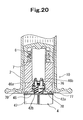
- the action of the prefilled syringe 1 of the present invention is described below with reference to Figs. 19 through 21 .
- the gasket 3 is accommodated inside the proximal portion of the outer cylinder 2.
- the plunger 4 is entered into the hollow part of the plunger-mounting member 7 from the mounting distal part 40 of the plunger 4 with the plunger 4 being rotated.
- the spiral projected portion 42 (42a, 42b) of the mounting distal part 40 of the plunger 4 screws the spiral concave portion 79 of the plunger-mounting part of the plunger-mounting member 7.
- the engaging portion 41 of the mounting distal part 40 of the plunger 4 proceeds toward the engaging rib 76 of the plunger-mounting member 7.
- the convex portions 46a, 46b, 46c, and 46d of the claw portions 43a, 43b, 43c, and 43d of the plunger 4 ride across the engaging rib 76 of the plunger-mounting member 7.
- the convex portions 46a, 46b, 46c, and 46d engage the engaging rib 76 of the plunger-mounting member 7. In this manner, the mounting of the plunger 4 on the prefilled syringe body 10 finishes.
- the engaging portion 41 of the mounting distal part 40 of the plunger 4 and the engaging rib 76 of the plunger-mounting member 7 engage each other.
- an operator can confirm through a bodily sensation during the plunger-mounting work that the engaging rib of the plunger-mounting part and the engaging portion of the plunger have engaged each other.
- the plunger 4 mounted on the prefilled syringe body 10 is locked to the engaging rib 76 of the plunger-mounting member 7 in such a way that the plunger 4 does not separate from the prefilled syringe body 10.
- a prefilled syringe of another embodiment of the present invention is described below with reference to drawings.
- a prefilled syringe 50 of the embodiment shown in Figs. 22 and 23 has a prefilled syringe body 10a and the plunger 4 which can be mounted on the prefilled syringe body 10a (gasket 3) and is not mounted thereon.
- the prefilled syringe body 10a has the outer cylinder 2, the sealing member 5 for sealing the opening formed at the distal end of the outer cylinder 2, the gasket 3 slidably accommodated inside the outer cylinder 2, and the medicine 8 accommodated inside the medicine accommodation part formed inside the outer cylinder 2.
- the gasket 3 is composed of the gasket body 6 and a plunger-mounting member 7a mounted on the gasket body 6.
- the prefilled syringe 50 of this embodiment is different from the above-described prefilled syringe 1 in only the construction of the plunger-mounting member of the gasket 3. Because the gasket body, the outer cylinder, and the plunger of the prefilled syringe 50 are the same as those of the prefilled syringe 1, only the plunger-mounting member 7a is described below.
- the gasket 6 is located at a position distal from the opening formed at the proximal end of the outer cylinder 2 by a predetermined length.
- the proximal end of the plunger-mounting member 7a is also located at a position distal from the opening formed at the proximal end of the outer cylinder 2 by a predetermined length.
- the space between the opening formed at the proximal end of the outer cylinder 2 and the proximal end of the plunger-mounting member 7a is formed as a guide portion for guiding the plunger 4 to the plunger-mounting member 7a.
- the plunger-mounting member 7a is a tubular body, having a predetermined length, which has a hollow part penetrating therethrough from one end thereof to the other end thereof.
- the plunger-mounting member 7a has the body part 70a, the distal part 71 which is projected distally from the body part 70a and can be accommodated inside the lumen part 60 of the gasket body 6, and the plunger-mounting part, formed inside the proximal portion of the body part 70a, on which the plunger 4 is to be mounted.
- the body part 70a is a tubular part having an axially shorter length than the body part 70 of the above-described plunger-mounting member 7 and has the plunger-mounting part at its proximal portion.
- the gasket body 6 is located at the position distal from the opening formed at the proximal end of the outer cylinder 2 by the predetermined length.
- the proximal end of the plunger-mounting member 7a mounted on the gasket body 6 is also located at the position distal from the opening formed at the proximal end of the outer cylinder 2 by the predetermined length. Because in this embodiment, the proximal portion of the outer cylinder 2 constructs the guide portion for guiding the plunger 4 to the plunger-mounting member 7a, the operation of mounting the plunger 4 on the plunger-mounting member 7a can be preferably performed.
- the length of the guide portion (the distance between the opening formed at the proximal end of the outer cylinder 2 and the proximal end of the plunger-mounting member 7a) is preferably 15 to 40mm and especially preferably 20 to 30mm.
- the tubular body part 70a has a plurality of the side plate portions 81 axially extended on its side surface.
- the body part 70a has the disk-shaped distal side flange part 72 capable of pressing the proximal end surface of the gasket body 6 at its distal end.
- the body part 70a has the disk-shaped proximal side flange part 73 capable of contacting the pressing part 48 of the plunger 4 at its proximal end.
- a plurality of the side plate portions 81 connects the distal side flange part 72 and the proximal side flange part 73 to each other and reinforces both flange parts 72 and 73.
- the outer edge of the distal side flange part 72 is almost circular.
- the outer diameter of the distal side flange part 72 is set a little smaller than that of the proximal end of the gasket body 6.
- the peripheral portion of the distal side flange part 72 at its distal side is formed as a substantial flat surface which contacts and is capable of pressing the proximal end surface of the gasket body 6.
- the proximal side flange part 73 has a flat plate portion and a collar portion extended by a predetermined length from the flat plate portion toward the proximal end of the plunger-mounting member 7a.
- the proximal side flange part 73 has the outer collar 77 and the inner collar 78 both extended a little from the flat plate portion toward the proximal end of the plunger-mounting member 7a.
- the outer collar 77 and the inner collar 78 are concentrically formed.
- the distal end (free end) of the outer collar 77 and that of the inner collar 78 are formed flatly.
- the distal end (free end) of the inner collar 78 is projected a little beyond the distal end of the outer collar 77.
- the distal part 71 projected from the body part 70a is a cylindrical part which has an almost equal outer diameter and a predetermined length.
- the distal part 71 is formed longer than the body part 70a.
- the distal part 71 is projected distally from the vicinity of the center of the distal side flange part 72 of the body part 70a.
- the distal part 71 does not contact the inner surface of the distal portion of the gasket body 6.
- the spiral ribs 74, 75 are formed on the outer surface of the distal portion of the distal part 71 of the plunger-mounting member 7a. As shown in Figs.
- each of the spiral ribs 74, 75 has a start point located at a position in the vicinity of the distal end of the distal part 71 of the plunger-mounting member 7a and is extended toward the proximal end of the distal part 71 by a predetermined length.
- the plunger-mounting member has a plurality of the spiral ribs (specifically, two lines), the spiral rib may be composed of only one line (one piece).
- the height of the annular projected part of the gasket body 6 and that of the spiral rib of the plunger-mounting member 7a are set as follows:
- the height of the annular projected part of the gasket body 6 is favorably 1.0 to 3.0mm and more favorably 1.5 to 2.5mm.
- the height of the spiral rib of the plunger-mounting member 7a is favorably 2.5 to 3.2mm, more favorably 2.8 to 3.1mm, and most favorably 2.95 to 3.05mm.
- the width of a contact portion of the annular projected part and a contact portion of the spiral rib is favorably 0.5 to 2.5mm and especially favorably 1.0 to 2.3mm.
- the inner diameter of the annular projected part of the gasket body 6 is favorably 16.0 to 20.0mm and especially favorably 17.0 to 19.0mm.
- the outer diameter of the spiral rib of the plunger-mounting member 7a is favorably 19.0 to 22.0mm and especially favorably 20.0 to 21.0mm.
- the gasket body 6 has the spiral projection 66 for forming the spiral screwing part 63.
- the plunger-mounting member 7a has a rib, formed on the outer surface of the distal part 71 that can be accommodated inside the lumen part 60 of the gasket body 6, which contacts the spiral projection 66 of the gasket body 6 in mounting the plunger-mounting member 7a on the gasket body 6, thus constituting a resistance to the rotation of the plunger-mounting member 7a inside the gasket body 6.
- the plunger-mounting member 7a of this embodiment has an axial rib 91 formed on a side surface of the tubular distal part 71 at a position thereof proximal from the portion thereof where the spiral ribs 74, 75 are formed.
- a plurality of the axial ribs 91 is formed.
- the axial rib 91 contacts (contacts at a higher frictional force than a predetermined frictional force) the spiral projection 66 formed on the inner surface of the gasket body 6, thus preventing the plunger-mounting member 7a from idling with respect to the gasket body 6. More specifically, in mounting the plunger-mounting member 7a on the gasket body 6, the axial rib 91 of the plunger-mounting member 7a presses the spiral projection 66 of the gasket body 6 a little.
- the axial rib 91 is extended from the distal side flange part 72 toward the distal end of the plunger-mounting member 7a and in parallel with the axis of the plunger-mounting member 7a and terminates at a position of the tubular distal part 71 located a little proximally from the portion thereof where the spiral ribs 74, 75 are formed.
- the height of the axial rib 91 of the plunger-mounting member 7a is preferably 0.5 to 2mm.
- the number of the axial ribs 91 is favorably two to eight and especially favorably three to six.
- the diameter of a circle which passes the outer surface of the axial rib 91 of the plunger-mounting member 7a is favorably a little larger and more favorably 1 to 2mm larger than the diameter of a circle which passes the outer surface of the spiral projection 66 of the gasket body 6.
- a rib 93 which is extended toward the center of the plunger-mounting member 7a from the peripheral edge of the distal end surface of the distal side flange part 72 and reaches the above-described axial rib 91.
- Two ribs 93 are formed by opposing them to each other.
- the rib 93 is pressed against the gasket. Thereby the plunger-mounting member is prevented from idling with respect to the gasket.
- a concave portion 90 is formed on a side surface of the distal side flange part 72. Two concave portions 90 are formed by opposing them to each other.
- the plunger-mounting part for accommodating the mounting distal part 40 of the plunger 4 therein and mounting the mounting distal part 40 thereon is formed on the inner surface of the hollow part of the plunger-mounting member 7a.
- the plunger-mounting part has the spiral concave portion 79 on which the spiral projected portion 42 (42a, 42b) of the mounting distal part 40 is to screw and the engaging rib 76, located at a position in the vicinity of the spiral concave portion 79 and distal therefrom, which is to engage the engaging portion 41 of the mounting distal part 40. As shown in Figs.
- the plunger-mounting member 7a has the large-diameter opening 84 at its proximal end.
- the spiral concave portion 79 is formed on the inner surface of a lumen part having a smaller diameter than the large-diameter opening 84.
- the spiral concave portion 79 has a start point located at a position a little distal from the opening formed at the proximal end of the plunger-mounting member 7a and is extended toward the distal side of the plunger-mounting member 7a by a predetermined length.
- the spiral concave portion 79 is composed of two lines (two pieces).
- the plunger-mounting member 7a has the spiral concave portion composed of a plurality of lines (specifically, two lines), the spiral concave portion may be composed of only one line (one piece).
- the plunger-mounting part has the engaging rib 76 located at a position in the vicinity of the spiral concave portion 79 and distal therefrom.
- the engaging rib 76 engages the engaging portion 41 of the mounting distal part 40 of the plunger 4 to be described later.
- the inner surface of the engaging rib 76 forms the annular tapered configuration which tapers such that the inner diameter of the engaging rib 76 becomes gradually smaller toward the distal end of the plunger-mounting member 7a.
- This construction allows the engaging portion 41 of the plunger 4 to be described later to easily enter the plunger-mounting part and pass therethrough.
- the distal end surface of the engaging rib 76 is formed erectly from the body part 70, in other words, as an annular flat surface almost orthogonal to the axis of the body part 70a. Therefore the engaging rib 76 which has engaged the engaging portion 41 of the plunger 4 to be described later is prevented from separating therefrom.
- the engaging rib 76 is annular, the engaging rib 76 may be dashed line-shaped (uncontinuous).
- hard or semi-hard resin such as high-density polyethylene, polypropylene, polystyrene, and polyethylene terephthalate.
- the outer cylinder 2 also accommodates the gasket 3 having the gasket body 6 on which the plunger-mounting member 7a is mounted.
- the proximal end of the plunger-mounting member 7a is not substantially projected beyond the proximal end of the outer cylinder 2, but is located at a position distal from the proximal end of the outer cylinder 2 by a predetermined length.
- the plunger-mounting member 7a is mounted on the gasket body 6, as described below.
- the plunger-mounting member 7a After the spiral ribs 74, 75 of the plunger-mounting member 7a are inserted into the gasket body 6 from the start point of the spiral screwing part 63, the plunger-mounting member 7a is rotated. Thereby, screwing between the spiral screwing part 63 and the spiral ribs 74, 75 progresses. During the progress of the screwing therebetween, the axial rib 91 of the plunger-mounting member 7a proceeds with the axial rib 91 pressing the spiral projection 66 of the gasket body 6 a little and sliding in contact therewith.
- the start points of the spiral ribs 74, 75 of the plunger-mounting member 7a approach the termination point of the spiral screwing part 63 of the gasket body 6 and the rib-absent portion 65 of the annular projected part 64 thereof and are positioned between the spiral projection 66 forming the spiral screwing part 63 and the annular projected part 64.
- the spiral ribs 74, 75 pass the rib-absent portion 65 of the annular projected part 64 and enter the accommodation part 62.
- the spiral ribs 74, 75 entirely pass the rib-absent portion 65 of the annular projected part 64, and the portion of the distal part 71 of the plunger-mounting member 7a where the spiral ribs 74, 75 are formed is accommodated inside the accommodation part 62 of the gasket body 6.
- the axial rib 91 of the plunger-mounting member 7a maintains a state in which the axial rib 91 presses the spiral projection 66 of the gasket body 6 a little. Thereby the work of mounting the plunger-mounting member 7a on the gasket body 6 finishes.
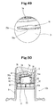
- the action of the prefilled syringe 50 of this embodiment is described below with reference to Figs. 29 and 30 .
- the gasket 3 is accommodated inside the outer cylinder 2 at a position distal from the proximal end of the outer cylinder 2 by a predetermined length.
- the plunger 4 is entered into the outer cylinder 2 from the opening formed at the proximal end thereof and thereafter into the hollow part of the plunger-mounting member 7a with the plunger 4 being rotated.
- the spiral projected portion 42 (42a, 42b) of the mounting distal part 40 of the plunger 4 screws the spiral concave portion 79 of the plunger-mounting part of the plunger-mounting member 7a.
- the engaging portion 41 of the mounting distal part 40 of the plunger 4 proceeds toward the engaging rib 76 of the plunger-mounting member 7a.
- the convex portions 46a, 46b, 46c, and 46d of the claw portions 43a, 43b, 43c, and 43d of the plunger 4 ride across the engaging rib 76 of the plunger-mounting member 7a.
- the convex portions 46a, 46b, 46c, and 46d engage the engaging rib 76 of the plunger-mounting member 7a.
- the mounting of the plunger 4 on the prefilled syringe body 10a finishes.
- the plunger 4 is inserted into the outer cylinder 2, the plunger 4 reaches the plunger-mounting member 7a with the plunger 4 being almost parallel with the axis of the outer cylinder.
- the engaging portion 41 of the mounting distal part 40 of the plunger 4 and the engaging rib 76 of the plunger-mounting member 7a engage each other.
- an operator can confirm through a bodily sensation during the plunger-mounting work that the engaging rib of the plunger-mounting part and the engaging portion of the plunger have engaged each other.
- the plunger mounted on the prefilled syringe body 10a is locked to the engaging rib 76 of the plunger-mounting member 7a in such a way that the plunger 4 does not separate from the prefilled syringe body 10a.
- the plunger-mounting member may have a construction as shown in Figs. 31 and 32 .
- the only difference between a plunger-mounting member 7b of this embodiment and the above-described plunger-mounting member 7a is that the latter has the axial rib 91 on the side surface of the tubular distal part 71, whereas the former does not have the axial rib 91 thereon.
- the plunger-mounting member may have a construction as shown in Figs. 33 and 34 .
- the above-described plunger-mounting member 7a has the axial rib.
- a plunger-mounting member 7c of this embodiment does not have the axial rib, but has an annular rib 92 on the side surface of the tubular distal part 71.
- the plunger-mounting member 7c of this embodiment has the annular rib 92 formed on the side surface of the tubular distal part 71 at a position thereof proximal from the portion thereof where the spiral ribs 74, 75 are formed.
- the annular rib 92 is formed endlessly and orthogonally to the axis of the plunger-mounting member 7c.
- the annular rib 92 contacts (contacts at a higher frictional force than a predetermined frictional force) the spiral projection 66 formed on the inner surface of the gasket body 6, thus preventing the plunger-mounting member 7c from idling with respect to the gasket body 6. More specifically, in mounting the plunger-mounting member 7c on the gasket body 6, the annular rib 92 of the plunger-mounting member 7c presses the spiral projection 66 of the gasket body 6 a little.
- the height of the annular rib 92 of the plunger-mounting member 7c is preferably 0.5 to 2mm.
- the outer diameter of the annular rib 92 of the plunger-mounting member 7c is favorably a little larger and especially favorably 1 to 2mm larger than the diameter of a circle which passes the outer surface of the spiral projection 66 of the gasket body 6.
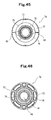
- the plunger-mounting member may have a construction as shown in Figs. 35 and 36 .
- the above-described plunger-mounting member 7a has the axial rib.
- a plunger-mounting member 7d of this embodiment does not have the axial rib, but has a first annular rib 92 and a second annular rib 94 on the side surface of the tubular distal part 71. More specifically, the plunger-mounting member 7d of this embodiment has the first annular rib 92 formed on the side surface of the tubular distal part 71 at a position thereof proximal from the portion thereof where the spiral ribs 74, 75 are formed.
- the first annular rib 92 is formed endlessly and orthogonally to the axis of the plunger-mounting member 7d.
- the first annular rib 92 contacts (contacts at a higher frictional force than a predetermined frictional force) the spiral projection 66 formed on the inner surface of the gasket body 6, thus preventing the plunger-mounting member 7d from idling with respect to the gasket body 6. More specifically, in mounting the plunger-mounting member 7d on the gasket body 6, the first annular rib 92 of the plunger-mounting member 7d presses the spiral projection 66 of the gasket body 6 a little.
- the plunger-mounting member 7d of this embodiment has the second annular rib 94 formed on the side surface of the tubular distal part 71 at a portion thereof located between the above-described first annular rib 91 formed on the tubular distal part 71 and the distal side flange part 72.
- the second annular rib 94 is formed endlessly and orthogonally to the axis of the plunger-mounting member 7d.
- the second annular rib 94 contacts (contacts at a higher frictional force than a predetermined frictional force) the spiral projection 66 formed on the inner surface of the gasket body 6, thus preventing the plunger-mounting member 7d from idling with respect to the gasket body 6.
- the second annular rib 94 of the plunger-mounting member 7d presses the spiral projection 66 of the gasket body 6 a little.
- the height of the first annular rib 92 of the plunger-mounting member 7d and that of the second annular rib 94 thereof are preferably 0.5 to 2mm.
- the outer diameter of the first annular rib 92 of the plunger-mounting member 7d and that of the second annular rib 94 thereof are favorably a little larger and especially favorably 1 to 2mm larger than the diameter of the circle which passes the outer surface of the spiral projection 66 of the gasket body 6.
- the number of the annular rib is not limited to one or two, but may be not less than three and favorably one to three.
- the plunger-mounting member may have a construction as shown in Figs. 37 and 38 .
- the only difference between a plunger-mounting member 7e of this embodiment and the above-described plunger-mounting member 7a is that the former has the annular rib 92 formed on the side surface of the tubular distal part 71.
- the plunger-mounting member 7e of this embodiment has the axial rib 91 formed on the side surface of the tubular distal part 71 at a position thereof proximal from the portion where the spiral ribs 74, 75 are formed. In this embodiment, a plurality of the axial ribs 91 is formed.
- the axial ribs 91 In the case where a plurality of the axial ribs 91 is formed, it is preferable to dispose the axial ribs 91 in such a way that they form an almost equal angle with the axis of the distal part 71. As shown in Figs. 37 and 38 , the axial rib 91 contacts (contacts at a higher frictional force than a predetermined frictional force) the spiral projection 66 formed on the inner surface of the gasket body 6, thus preventing the plunger-mounting member 7e from idling with respect to the gasket body 6.
- the axial rib 91 of the plunger-mounting member 7e presses the spiral projection 66 of the gasket body 6 a little.
- the axial rib 91 is extended from the distal side flange part 72 toward the distal end of the plunger-mounting member 7e and in parallel with the axis of the plunger-mounting member 7e and terminates at a position of the distal part 71 a little proximal from the portion thereof where the spiral ribs 74, 75 are formed.
- the plunger-mounting member 7e of this embodiment has the annular rib 92 formed on the side surface of the tubular distal part 71 at a position thereof proximal from the portion thereof where the spiral ribs 74, 75 are formed.
- the annular rib 92 is formed endlessly and orthogonally to the axis of the plunger-mounting member 7e.
- the annular rib 92 is continuous with the termination points of a plurality of the axial ribs 91.
- the annular rib 92 also contacts (contacts at a higher frictional force than a predetermined frictional force) the spiral projection 66 formed on the inner surface of the gasket body 6, thus preventing the plunger-mounting member 7e from idling with respect to the gasket body 6.
- the annular rib 92 of the plunger-mounting member 7e presses the spiral projection 66 of the gasket body 6 a little.
- the height of the annular rib 92 of the plunger-mounting member 7e is preferably 0.5 to 2mm.
- the outer diameter of the annular rib 92 of the plunger-mounting member 7e is favorably a little larger and especially favorably 1 to 2mm larger than the diameter of a circle which passes the outer surface of the spiral projection 66 of the gasket body 6.
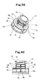
- the plunger-mounting member may have a construction as shown in Figs. 39 and 40 .
- the only difference between a plunger-mounting member 7f of this embodiment and the above-described plunger-mounting member 7a is that the former has the first annular rib 92 and the second annular rib 94 formed on the side surface of the tubular distal part 71.
- the plunger-mounting member 7f of this embodiment has the axial rib 91 formed on the side surface of the tubular distal part 71 at a position thereof proximal from the portion thereof where the spiral ribs 74, 75 are formed. In this embodiment, a plurality of the axial ribs 91 is formed.
- the axial ribs 91 In the case where a plurality of the axial ribs 91 is formed, it is preferable to locate the axial ribs 91 in such a way that they form an almost equal angle with the axis of the distal part 71. As shown in Figs. 39 and 40 , the axial rib 91 contacts (contacts at a higher frictional force than a predetermined frictional force) the spiral projection 66 formed on the inner surface of the gasket body 6, thus preventing the plunger-mounting member 7f from idling with respect to the gasket body 6.
- the axial rib 91 of the plunger-mounting member 7f presses the spiral projection 66 of the gasket body 6 a little.
- the axial rib 91 is extended from the distal side flange part 72 toward the distal end of the plunger-mounting member 7f and in parallel with the axis of the plunger-mounting member and terminates at a position of the distal part 71 a little proximal from the portion where the spiral ribs 74, 75 are formed.
- the plunger-mounting member 7f of this embodiment has the first annular rib 92 formed on the side surface of the tubular distal part 71 at a position thereof proximal from the portion thereof where the spiral ribs 74, 75 are formed.
- the first annular rib 92 is formed endlessly and orthogonally to the axis of the plunger-mounting member 7f.
- the first annular rib is continuous with the termination points of a plurality of the axial ribs 91.
- the first annular rib 92 also contacts (contacts at a higher frictional force than a predetermined frictional force) the spiral projection 66 formed on the inner surface of the gasket body 6, thus preventing the plunger-mounting member 7f from idling with respect to the gasket body 6. More specifically, in mounting the plunger-mounting member 7f on the gasket body 6, the first annular rib 92 of the plunger-mounting member 7f presses the spiral projection 66 of the gasket body 6 a little.
- the plunger-mounting member 7f of this embodiment has the second annular rib 94 formed on the side surface of the tubular distal part 71 at a portion thereof located between the above-described first annular rib 91 formed on the tubular distal part 71 and the distal side flange part 72.
- the second annular rib 94 is formed endlessly and orthogonally to the axis of the plunger-mounting member 7f.
- the second annular rib 94 is continuous with intermediate portions of a plurality of the axial ribs 91.
- the second annular rib 94 also contacts (contacts at a higher frictional force than the predetermined frictional force) the spiral projection 66 formed on the inner surface of the gasket body 6, thus preventing the plunger-mounting member 7f from idling with respect to the gasket body 6. More specifically, in mounting the plunger-mounting member 7f on the gasket body 6, the second annular rib 94 of the plunger-mounting member 7f presses the spiral projection 66 of the gasket body 6 a little.
- the height of the first annular rib 92 of the plunger-mounting member 7f and that of the second annular rib 94 thereof are preferably 0.5 to 2mm.
- the outer diameter of the first annular rib 92 of the plunger-mounting member 7f and that of the second annular rib 94 thereof are favorably a little larger and especially favorably 1 to 2mm larger than the diameter of the circle which passes the outer surface of the spiral projection 66 of the gasket body 6.
- the plunger-mounting member may have a construction as shown in Figs. 41 through 49 .
- a plunger-mounting member 7g is a tubular body, having a predetermined length, which has a hollow part penetrating therethrough from one end thereof to the other end thereof.
- the plunger-mounting member 7g has the body part 70a, the distal part 71 which is projected distally from the body part 70a and can be accommodated inside the lumen part of the gasket body 6, and the plunger-mounting part, formed inside the proximal portion of the body part 70a, on which the plunger 4 is to be mounted.
- the body part 70a is a tubular part having an axially shorter predetermined length than the body part 70 of the above-described plunger-mounting member 7 and has the plunger-mounting part at its proximal portion.
- the gasket body 6 is located at a position distal by a predetermined length from the opening formed at the proximal end of the outer cylinder 2.
- the proximal end of the plunger-mounting member 7g mounted on the gasket body 6 is also located at a position distal by a predetermined length from the opening formed at the proximal end of the outer cylinder 2.
- the proximal portion of the outer cylinder 2 constructs the guide portion for guiding the plunger 4 to the plunger-mounting member 7g
- the operation of mounting the plunger 4 on the plunger-mounting member 7g can be preferably performed.
- the length of the guide portion (the distance between the opening formed at the proximal end of the outer cylinder 2 and the proximal end of the plunger-mounting member 7g) is preferably 15 to 40mm and especially preferably 20 to 30mm.
- the tubular body part 70a has a plurality of side plate portions 81 axially extended on its side surface.
- the body part 70a has the disk-shaped distal side flange part 72 capable of pressing the proximal end surface of the gasket body 6 at the distal end thereof.
- the body part 70a has the disk-shaped proximal side flange part 73 capable of contacting the pressing part 48 of the plunger 4 at its proximal end.
- a plurality of the side plate portions 81 connects the distal side flange part 72 and the proximal side flange part 73 to each other and reinforces both flange parts 72 and 73.
- the outer edge of the distal side flange part 72 is almost circular.
- the outer diameter of the distal side flange part 72 is set a little smaller than that of the proximal end of the gasket body 6.
- the peripheral portion of the distal side flange part 72 at its distal end is formed as an almost flat surface which contacts and is capable of pressing the proximal end surface of the gasket body 6.
- the proximal side flange part 73 has a flat plate portion and a collar portion extended by a predetermined length from the flat plate portion toward the proximal end of the plunger-mounting member 7g.
- the proximal side flange part 73 has the outer collar 77 and the inner collar 78 both extended a little from the flat plate portion toward the proximal end of the plunger-mounting member 7g.
- the outer collar 77 and the inner collar 78 are concentrically formed.
- the distal end (free end) of the outer collar 77 and that of the inner collar 78 are flat.
- the distal end (free end) of the inner collar 78 is projected a little beyond the distal end (free end) of the outer collar 77.
- the distal part 71 projected from the body part 70a is a cylindrical part which has an almost equal outer diameter and a predetermined length.
- the distal part 71 is formed longer than the body part 70a.
- the distal part 71 is projected distally from the vicinity of the center of the distal side flange part 72 of the body part 70a.
- the distal part 71 does not contact the inner surface of the distal part of the gasket body 6.
- the spiral ribs 74, 75 are formed on the outer surface of the distal portion of the distal part 71 of the plunger-mounting member 7g. As shown in Figs.
- each of the spiral ribs 74, 75 has a start point located at a position in the vicinity of the distal end of the distal part 71 of the plunger-mounting member 7g and is extended toward the proximal side of the plunger-mounting member 7g by a predetermined length.
- the plunger-mounting member 7g has a plurality of the spiral ribs (specifically, two lines), the spiral rib may be composed of only one line (one piece).
- the height of the annular projected part 64 of the gasket body 6 and that of the spiral rib of the plunger-mounting member 7g are set as follows:
- the height of the annular projected part 64 of the gasket body is favorably 1.0 to 3.0mm and more favorably 1.5 to 2.5mm.
- the height of the spiral rib of the plunger-mounting member 7g is favorably 2.5 to 3.2mm, more favorably 2.8 to 31mm, and most favorably 2.95 to 3.05mm.
- the inner diameter of the annular projected part 64 of the gasket body 6 is favorably 16.0 to 20.0mm and especially favorably 17.0 to 19.0mm.
- the outer diameter of the spiral rib of the plunger-mounting member 7g is favorably 19.0 to 22.0mm and especially favorably 20.0 to 21.0mm.
- the rib 93 is formed on the distal end surface of the distal side flange part 72. Specifically the rib 93 is extended toward the center of the plunger-mounting member 7g from the peripheral edge of the distal side flange part 72 and reaches the distal part 71. Two ribs 93 are formed by opposing them to each other. In mounting the plunger on the gasket with the plunger being pressed, the rib 93 is pressed against the gasket. Thereby the plunger-mounting member 7g is prevented from idling with respect to the gasket.
- the plunger-mounting part for accommodating the mounting distal part 40 of the plunger 4 therein and mounting the mounting distal part 40 thereon is formed on the inner surface of the hollow part of the plunger-mounting member 7g.
- the plunger-mounting part has the spiral concave portion 79 on which the spiral projected portion 42 (42a, 42b) of the mounting distal part 40 is to screw and the engaging rib 76, located at a position in the vicinity of the spiral concave portion 79 and distal therefrom, which is to engage the engaging portion 41 of the mounting distal part 40. As shown in Figs.
- the plunger-mounting member 7g has the large-diameter opening 84 at its proximal end.
- the spiral concave portion 79 is formed on the inner surface of a lumen part having a smaller diameter than the large-diameter opening 84.
- the spiral concave portion 79 has a start point at a position a little distal from the opening formed at the proximal end of the plunger-mounting member 7g and is extended by a predetermined length toward the distal side of the plunger-mounting member 7g.
- the spiral concave portion 79 is composed of two lines (two pieces). Although it is preferable that the plunger-mounting member 7g has a plurality of lines (specifically, two lines) of the spiral concave portion, the spiral concave portion may be composed of only one line (one piece).
- the plunger-mounting part has the engaging rib 76 located at a position in the vicinity of the spiral concave portion 79 and distal therefrom.
- the engaging rib 76 engages the engaging portion 41 of the mounting distal part 40 of the plunger 4 to be described later.
- the inner surface of the engaging rib 76 forms the annular tapered surface which tapers such that the diameter becomes gradually smaller toward the distal end side of the plunger-mounting member 7g. This construction allows the engaging portion 41 of the plunger 4 to be described later to easily enter the plunger-mounting part and pass therethrough.
- the distal end surface of the engaging rib 76 is formed erectly from the body part 70a, in other words, as an annular flat surface almost orthogonal to the axis of the body part 70a.
- the engaging rib 76 which has engaged the engaging portion 41 of the plunger 4 to be described later is prevented from separating therefrom.
- the engaging rib 76 is annular, the engaging rib 76 may be dashed line-shaped (uncontinuous).
- hard or semi-hard resin such as high-density polyethylene, polypropylene, polystyrene, and polyethylene terephthalate.
- the spiral ribs 74, 75 formed on the outer surfaces of the distal portions of the distal parts 71 of the plunger-mounting members of all of the above-described embodiments have the form in the end portion thereof as shown in Fig. 48 which is an enlarged view of the portion encircled with the round dashed line shown in Figs. 42 , 43, and 44 and the form in the end portion thereof as shown in Fig. 49 which is an enlarged view of the portion encircled with the round dashed line shown in Fig. 44 .
- Figs. 48 is an enlarged view of the portion encircled with the round dashed line shown in Figs. 42 , 43, and 44
- Fig. 49 which is an enlarged view of the portion encircled with the round dashed line shown in Fig. 44 .
- the spiral ribs 74, 75 have projected portions 74a, 75a respectively formed on the proximal end surface of the proximal portion thereof.
- the projected portions 74a, 75a are so formed as to be projected from the proximal end surfaces of the proximal portions of the spiral ribs 74, 75 respectively toward the disk-shaped distal side flange part 72 capable of pressing the proximal end surface of the gasket body 6.
- a resisting force acting between the gasket and the plunger-mounting member can be smaller than a resisting force acting between the plunger-mounting member and the plunger.
- the projected portions 74a, 75a prevent the plunger-mounting member from idling with respect to the gasket with the plunger being held together with the plunger-mounting member and thus the work of mounting the plunger on the plunger-mounting member from being difficult. That is, the projected portions 74a, 75a formed on the proximal end surfaces of the proximal portions of the spiral ribs 74, 75 respectively have the function of preventing the plunger-mounting member from idling with respect to the gasket.
- the projected portions 74a, 75a are formed at the proximal ends of the spiral ribs 74, 75 at positions distal from the proximal end thereof by a predetermined length. More specifically, each of the spiral ribs 74, 75 has an end portion not spiral but almost orthogonal to the axis of the plunger-mounting member 7g (the axis of the distal part 71) at the proximal portion thereof. The termination point of the end portion of each of the spiral ribs 74, 75 becomes gradually smaller toward the proximal end (termination point) thereof in its projected width (projected width with respect to the side surface of the distal part 71 of the plunger-mounting member 7g).
- the projected portions 74a, 75a are formed respectively on the end portions of the spiral ribs 74, 75 not spiral but almost orthogonal to the axis of the plunger-mounting member 7g (the axis of the distal part 71).
- the projected portions 74a, 75a are formed at portions of the spiral ribs 74, 75 where a normal projected width thereof is maintained (portion where the widths of the spiral ribs 74, 75 are not decreased).
- the projected height of the projected portions 74a, 75a with respect to the proximal end surface of the proximal portion of each of the spiral ribs 74, 75 is favorably 0.1 to 1mm and more favorably 0.2 to 0.5mm. It is preferable that the projected portions 74a, 75a have pointed apex portion (edge portion) respectively. It is preferable that the projected portions 74a, 75a are approximately triangular in the sections thereof. As shown in Figs. 48 and 49 , it is preferable that the angles of the projected portions 74a, 75a at the apex portions thereof are 15 to 60 degrees.
- angles of the projected portions 74a, 75a at the apex portions thereof are less than 15 degrees, they have a low strength and thus there is a fear that they may be broken.
- angles of the projected portions 74a, 75a at the apex portions thereof are more than 60 degrees, the amount of thrust of the apex portions thereof into the gasket is insufficient, and thus, to allow the apex portions to cut sufficiently into the gasket, it is necessary to make the height of the projected portions large, bringing a fear that it is difficult to mount the plunger-mounting member on the gasket at a production time.
- the ribs 93 are formed on the distal end surface of the distal side flange part 72.
- the projected portion 74a of the spiral rib 74 is so formed as to confront one of the ribs 93 formed on the distal side flange part 72 (specifically, the projected portion 74a of the spiral rib 74 is so formed as to axially confront one of the ribs 93, in other words, so formed as to position the projected portion 74a and one of the ribs 93 on the same straight line parallel with the axis of the plunger-mounting member 7g).
- the projected portion 75a of the spiral rib 75 is also so formed as to confront the other rib 93 formed on the distal side flange part 72 (specifically, the projected portion 75a of the spiral rib 75 is so formed as to axially confront the other rib 93, in other words, so formed as to position the projected portion 75a and the other rib 93 on the same straight line parallel with the axis of the plunger-mounting member 7g). As shown in Fig.
- a prefilled syringe 10b using the plunger-mounting member 7g has a form in which the gasket is sandwiched between the projected portion 74a of the spiral rib 74 and one of the ribs 93 of the distal side flange part 72.
- the prefilled syringe 10b has a form in which the gasket is sandwiched between the projected portion 75a of the spiral rib 75 and the other rib 93 of the distal side flange part 72.
- the outer cylinder 2 accommodates the gasket 3 having the gasket body 6 on which the plunger-mounting member 7g is mounted.
- the proximal end of the plunger-mounting member 7g is not substantially projected beyond the proximal end of the outer cylinder 2, but is located at the position distal from the proximal end of the outer cylinder 2 by the predetermined length.
- the plunger-mounting member 7g is mounted on the gasket body 6, as described below.
- the plunger-mounting member 7g After the spiral ribs 74, 75 of the plunger-mounting member 7g are inserted into the gasket body 6 from the start point of the spiral screwing part 63, the plunger-mounting member 7g is rotated. Thereby screwing between the spiral screwing part 63 and the spiral ribs 74, 75 progresses. During the progress of the screwing therebetween, the start points of the spiral ribs 74, 75 of the plunger-mounting member 7g approach the termination point of the spiral screwing part 63 of the gasket body 6 and the rib-absent portion 65 of the annular projected part 64 thereof and are positioned between the spiral projection 66 forming the spiral screwing part 63 and the annular projected part 64.
- the spiral ribs 74, 75 pass the rib-absent portion 65 of the annular projected part 64 and enter the accommodation part 62.
- the spiral ribs 74, 75 entirely pass the rib-absent portion 65 of the annular projected part 64, and the portion of the distal part 71 of the plunger-mounting member 7g where the spiral ribs are formed is accommodated inside the accommodation part 62 of the gasket body 6.
- the prefilled syringe of the present invention is as described below.
Landscapes
- Health & Medical Sciences (AREA)
- Vascular Medicine (AREA)
- Engineering & Computer Science (AREA)
- Anesthesiology (AREA)
- Biomedical Technology (AREA)
- Heart & Thoracic Surgery (AREA)
- Hematology (AREA)
- Life Sciences & Earth Sciences (AREA)
- Animal Behavior & Ethology (AREA)
- General Health & Medical Sciences (AREA)
- Public Health (AREA)
- Veterinary Medicine (AREA)
- Infusion, Injection, And Reservoir Apparatuses (AREA)
Abstract

Description
- The present invention relates to a prefilled syringe in which a medicine is filled in advance.
- Many syringes are conventionally used. Recently there are many cases in which syringes are used by mounting them on syringe pumps respectively. Many prefilled syringes in which a medicine is filled in advance are utilized in recent years. There is a case in which the prefilled syringe is used by mounting it on the syringe pump.
In inserting the gasket into the prefilled syringe, generally used is a method so-called a vacuum plugging in which after a medicine is filled inside the outer cylinder whose opening formed at its distal end is sealed, the gasket is disposed at an opening of the outer cylinder under a pressure-decreased atmosphere (under a vacuum atmosphere), and thereafter a normal pressure state is generated to insert the gasket into the outer cylinder. In a state in which the plunger has been mounted on the gasket, it is difficult to dispose the gasket at the opening of the outer cylinder. Thus a vacuum plugging work is performed without mounting the plunger on the gasket. Therefore generally the prefilled syringe necessitates a plunger-mounting work to be performed subsequently. To make it easy to perform the work of mounting the plunger on the gasket, prevent liquid from leaking in mounting the plunger on the gasket, and decrease the amount of the work of restraining the rise of an internal pressure, generally the prefilled syringe has a mounting mechanism of mounting the plunger on the gasket by screwing a male screw portion formed on the plunger on a female screw portion formed on the gasket. - As described above, there are cases in which a medicine is given to a patient by using the syringe or the prefilled syringe by mounting them on the syringe pump. In the case where the syringe pump is used, continuous dosing of a very small amount of the medicine is performed. When the syringe pump is placed at a position higher than the patient, there is a possibility of the occurrence of a phenomenon in which the medicine is rapidly administered to the patient owing to a fall. That is, in such a state, a negative pressure is generated inside the syringe owing to the fall, and thus the gasket is sucked to the front side of the outer cylinder. The continuous dosing of a very small amount of the medicine is accomplished while a means for pressing the syringe pump fixed to the plunger is preventing the movement of the gasket caused by the sucking. When the negative pressure overcomes the engaging force acting between the plunger and the gasket, there is a danger that the gasket separates from the plunger. When the gasket separates from the plunger, the medicine inside the syringe is rapidly administered to the patient.
- As syringes having a mechanism of preventing the separation of the gasket from the plunger, Japanese Patent Application Laid-Open No.
2002-272843 2009-142508 WO01-97885 2007-202822
Syringes in which the gasket is constructed of a gasket body and a plunger-mounting member are proposed. As such syringes, for example, Japanese Utility Model Application Laid-Open No.6-39005 2007-44159 2008-307237 3665646 patent document 8,WO95-30444 - A syringe 1 of the patent document 1 (Japanese Patent Application Laid-Open No.
2002-272843 outer cylinder 2, agasket 3 capable of sliding inside theouter cylinder 2, and aplunger 4, having the function of performing the operation of moving thegasket 3, which is inserted into theouter cylinder 2 from the opening formed at the proximal end thereof. Theliquid 7 is liquid-tightly accommodated in advance inside the space surrounded with theouter cylinder 2 and thegasket 3. The flange 44 is formed at the head part 43 formed at the distal portion of theplunger 4. Thegasket 3 has the hollow part 33. The screw thread 34 is formed on the inner surface of the proximal side of the hollow part 33. The space 35 for accommodating the flange 44 is formed at a portion located distally from the screw thread 34. The flange 44 which has entered the space 35 across the screw thread 34 engages the space 35 in a loosely engage state.
In this syringe, the flange 44 formed at the head part 43 of the distal portion of theplunger 4 is not screwlike. Thus when a medicine is administered to a patient by the syringe mounted on the syringe pump with the syringe pump placed at a position higher than the patient, there is a fear that the plunger separates from the gasket. - The
syringe 10 of the patent document 2 (Japanese Patent Application Laid-Open No.2009-142508 gasket 3, theouter cylinder 2, and theplunger 4. Theplunger 4 has the spiral rib 44 formed on the outer surface of thehead part 42. Thegasket 3 has the spiral screwing part 33 which is to screw the spiral rib 44, the annular rib 34, for preventing the separation of the plunger from the gasket, which is located at a position in the vicinity of the spiral screwing part 33 and distal therefrom, and the accommodation part 32 for accommodating the portion where the spiral rib 44 of thehead part 42 of the plunger is formed. The annular rib 34 has the rib-absent portion 35 for guiding the spiral rib 44 which has reached the annular rib owing to the progress of the screwing between the spiral rib 44 of the plunger and the spiral screwing part 33 of the gasket to the accommodation part.
This syringe is effective for preventing the separation of the plunger from the gasket. But in dependence on a manner of the work of mounting the plunger on the gasket, defective mounting of the plunger on the gasket sometimes occurs.
In a syringe of the patent document 3 (International PublicationWO01-97885 plunger 4, the head part (coupling portion) 43 to be inserted into the hollow part 33 of thegasket 3 and coupled to thegasket 3 is formed. Amale screw 51 is formed on the outer circumferential surface of the head part 43. Thefemale screw 52 on which themale screw 51 can be screwed is formed on the inner circumferential surface of the hollow part 33 of thegasket 3. The head part 43 has theelastic piece 61 located at a position distal from themale screw 51 and the projectedportions 62, projectingly formed toward the outer circumference thereof, which are located in the vicinity of the end portions ofelastic pieces 61. The ring-shaped engaging projectedpart 63 is formed on the inner circumferential surface of the hollow part 33 of thegasket 3 at a position distal from thefemale screw 52.
In this syringe, the plunger is mounted on the gasket by rotating the plunger. Thus it is necessary to perform the operation of rotating the plunger to mount the plunger on the gasket. There is a case in which a screwing operation is not properly performed. In this state, there is a possibility that the outer side surface of the gasket is not a perfect circle and thus a liquid may leak. Further a stress generated when the plunger mounted on the gasket is inclined is directly transmitted to the gasket and the liquid may leak. - The plunger used for the syringe of the patent document 4 (Japanese Patent Application Laid-Open No.
2007-202822 plunger rod 22 and the gasket 21. The gasket 21 has the inner space whose distal end is closed and has an opening 212, having a smaller diameter than that of the inner space, which is formed at the proximal end thereof. The male screw-shaped projected part 223 is formed at the distal end of theplunger rod 22. When the projected part 223 enters the inner space across the opening 212, the gasket 21 and theplunger rod 22 engage each other in a free fit-on state.
The "opening having a smaller diameter" of the syringe is "not screwlike", and necessarily has the function of preventing the plunger from dropping when the plunger is rotated reversely and in addition preventing the plunger from dropping when the plunger is pulled toward the proximal end of the syringe. Therefore the "opening having a smaller diameter" is required to have a high strength. Thus when improper screwing occurs between the projected part 223 of theplunger rod 22 and the convexity of the female screw of the gasket, the convexity screws the projected portion 223 with the convexity being twisted. As a result, the circularity of the peripheral side surface of the gasket becomes low and there is a possibility that a liquid may leak. - In the patent document 5 (Japanese Utility Model Application Laid-Open No.
6-39005 syringe 2 serving as a container. The reinforcing material 30 reinforces theperipheral wall portion 23 forming the inner chamber portion of the plunger 20. Theplunger rod 10 is removably mounted on the reinforcing material 30. The insertion portion 16 of theplunger rod 10 is inserted into the insertion hole 34 (seeFig. 2 of the specification of the patent document 5) of the cover portion 32 of the reinforcing material 30. Theplunger rod 10 is rotated to fit the opposed side 18 of the window spline 17 of the insertion portion 16 of theplunger rod 10 on the fit-on groove 36 (seeFig. 3 of the specification of the patent document 5) of the back surface 35 of the cover portion 32 of the reinforcing material 30. Thereby the mounting of theplunger rod 10 on the plunger 20 on which the reinforcing material 30 has been mounted finishes.
In this syringe, at the time the plunger-mounting work is performed, it is necessary to fit the window spline on the slit-like fit-on groove and in addition, the plunger 20 is invisible because the plunger rod stands in the way. Thus it is not easy to perform the mounting work. In addition, after the mounting work finishes, there is a danger that when the window spline is fitted on the fit-on groove, the plunger rod easily separates from the plunger. - The syringe 1 of the patent document 6 (Japanese Patent Application Laid-Open No.
2007-44159 outer cylinder 2, thegasket 3 capable of sliding inside theouter cylinder 2, and theplunger 4 for performing the operation of moving thegasket 3. Thegasket 3 and theplunger 4 are coupled to each other by a coupling mechanism. Theplunger 4 is composed of theupper plunger 41 and thelower plunger 42 fitted thereon. At the time of fitting thelower plunger 41 on theupper plunger 42, the convex portion 422 formed on thelower plunger 42 is inserted into the concave portion 412 formed on theupper plunger 41. When the convex portion 422 is inserted deep into the concave portion 412, thelower plunger 42 is rotated until the convex portion 422 formed on thelower plunger 42 is positioned at the end of the concave portion 412 formed on theupper plunger 41. At this time, theupper plunger 41 and thelower plunger 42 are engaged each other in a loosely engage state by providing the gap at the engaging portion where theupper plunger 41 and thelower plunger 42 engage each other. This syringe also necessitates a rotation operation to be performed to mount the plunger on the gasket.
In the prefilled syringe of the patent document 7 (Japanese Patent Application Laid-Open No.2008-307237
Similarly to the syringe of thepatent document 6, in this syringe, it is not easy to perform a mounting work. - The syringe of the patent document 8 (Japanese Patent No.
3665646 WO95-30444 Figs. 1 through 6 of the specification thereof has the barrel, the plunger, and the plunger rod. By driving the plunger rod, the plunger generates an axial tensile force. As a result, the diameter of the plunger decreases. With the friction between the inside of the barrel and the plunger being decreased owing to the contraction of the diameter of the plunger, the elongation of the plunger is so restricted that the sealing between the inside of the barrel and the plunger is maintained. The plunger rod has the rod member and the connection member for the plunger. The rod member is axially slidable with respect to the connection member. In the syringe of the embodiment shown inFigs. 1 through 6 of the specification of thepatent document 7, theplunger insertion part 68 has thefemale screw 69 which engages themale screw 71 of theplunger rod 50. Theplunger rod 50 has themale screw 71 so designed that themale screw 71 engages thefemale screw 69 of theplunger insertion part 68. This syringe also necessitates a rotation operation to be performed to mount the plunger. The syringe of the embodiment shown inFigs. 7 through 18 of the specification of thepatent document 8 has the semicircular plunger rod distal end 164 having the convex surface projected toward the plunger. It is necessary to insert the distal end 164 into the cross-shaped slit shown inFig. 18 and thereafter rotate the plunger. In this syringe, to mount the plunger on the plunger rod, it is necessary to perform the work of placing the distal end 164 in position and inserting the distal end 164 into the slit and the operation of rotating the plunger. As shown inFig. 11 , because the distal end 164 contacts and deforms the plunger, there is a high possibility that a liquid leaks.
Similarly to the syringes of thepatent documents -
- Patent document 1: Japanese Patent Application Laid-Open No.
2002-272843 - Patent document 2: Japanese Patent Application Laid-Open No.
2009-142508 - Patent document 3: International Publication
WO01-97885 - Patent document 4: Japanese Patent Application Laid-Open No.
2007-202822 - Patent document 5: Japanese Utility Model Application Laid-Open No.
6-39005 - Patent document 6: Japanese Patent Application Laid-Open No.
2007-44159 - Patent document 7: Japanese Patent Application Laid-Open No.
2008-307237 - Patent document 8: Japanese Patent No.
3665646 WO95-30444 - Therefore it is an object of the present invention to provide a prefilled syringe which allows an operator to confirm that a plunger has been mounted on a gasket during a work of mounting the plunger on the gasket, is capable of securely restraining the gasket mounted on the plunger from being removed therefrom, and is unlikely to deform the gasket, even though the plunger inclines.
- The prefilled syringe which achieves the above-described objects is as described below.
A prefilled syringe of this invention comprises a prefilled syringe body including an outer cylinder, a gasket slidably accommodated inside said outer cylinder, a sealing member for sealing an opening formed at a distal end of said outer cylinder, and a medicine accommodated inside a medicine accommodation part formed inside said outer cylinder; and a plunger which can be mounted on said gasket and is not mounted thereon; wherein said gasket is composed of a gasket body which is a tubular body whose distal end is closed and proximal end is open and has a lumen part extended from an opening formed at said proximal end thereof to a distal side thereof and a plunger-mounting member mounted on said gasket body; said plunger-mounting member has a body part which is a tubular body having a hollow part penetrating therethrough from one end thereof to other end thereof and has a distal side flange part capable of pressing a proximal end surface of said gasket body at a distal side thereof, a distal part which is projected distally from said body part and can be accommodated inside said lumen part of said gasket body, a spiral rib formed on an outer surface of said distal part, a proximal side flange part formed at a proximal side of said body part, and a plunger-mounting part formed inside a proximal portion of said body part on which said plunger is to be mounted; said gasket body has a spiral screwing part, formed on an inner surface of said lumen part, which is to screw said spiral rib of said plunger-mounting member and an accommodation part, disposed distally from said spiral screwing part of said lumen part, for accommodating a portion of said distal part of said plunger-mounting member where said spiral rib is formed: said plunger has a pressing part capable of pressing a proximal end surface of said proximal side flange part of said plunger-mounting member in mounting said plunger on said gasket and a mounting distal part, projected distally from said pressing part, which is capable of entering said plunger-mounting part of said plunger-mounting member; said plunger-mounting part of said plunger-mounting member has a spiral concave portion and an engaging rib located at a position in a vicinity of said spiral concave portion and distal therefrom; said mounting distal part of said plunger has a spiral projected portion capable of screwing said spiral concave portion of said plunger-mounting part and an engaging portion, disposed in a vicinity of said spiral projected portion and at a distal side thereof, which engages said engaging rib of said plunger-mounting part; wherein said plunger-mounting member is mounted on said gasket body in a state that said spiral rib is received in said accommodation part, a distal end of said plunger-mounting member does not contact an inner surface of said gasket body; and wherein said mounting distal part of said plunger does not contact said inner surface of said gasket body when said plunger is mounted on said gasket. -
-
Fig. 1 is a front view of a prefilled syringe of an embodiment of the present invention. -
Fig. 2 is a vertical sectional view of a prefilled syringe body of the prefilled syringe shown inFig. 1 . -
Fig. 3 is an enlarged front view of a gasket to be used for the prefilled syringe of the present invention. -
Fig. 4 is a sectional view taken along a line A-A ofFig. 3 . -
Fig. 5 is a sectional view of a gasket body to be used for the gasket shown inFig. 3 . -
Fig. 6 is a sectional view taken along a line B-B ofFig. 5 . -
Fig. 7 is a front view of a plunger-mounting member to be used for the gasket shown inFig. 3 . -
Fig. 8 is a plan view of the plunger-mounting member shown inFig. 7 . -
Fig. 9 is a bottom view of the plunger-mounting member shown inFig. 7 . -
Fig. 10 is a sectional view taken along a line C-C ofFig. 7 . -
Fig. 11 is a perspective view as viewed from a bottom surface side of the plunger-mounting member shown inFig. 7 . -
Fig. 12 is an enlarged front view of a plunger to be used for the prefilled syringe of the present invention. -
Fig. 13 is a perspective view of the plunger shown inFig. 12 . -
Fig. 14 is an enlarged plan view of the plunger shown inFig. 12 . -
Fig. 15 is an enlarged front view of a front side of the plunger shown inFig. 12 . -
Fig. 16 is a perspective view of a plunger of another example to be used for the prefilled syringe of the present invention. -
Fig. 17 is a front view of an outer cylinder to be used for the prefilled syringe of the present invention. -
Fig. 18 is a sectional view of a sealing member (sealing cap) to be used for the prefilled syringe of the present invention. -
Fig. 19 is an explanatory view for explaining the action in mounting the plunger on a prefilled syringe body of the prefilled syringe of the present invention. -
Fig. 20 is an explanatory view for explaining the action in mounting the plunger on the prefilled syringe body of the prefilled syringe of the present invention. -
Fig. 21 is an explanatory view for explaining the action in mounting the plunger on the prefilled syringe body of the prefilled syringe of the present invention. -
Fig. 22 is a front view of a prefilled syringe of another embodiment of the present invention. -
Fig. 23 is a vertical sectional view of a prefilled syringe body of the prefilled syringe shown inFig. 22 . -
Fig. 24 is a front view of a plunger-mounting member to be used for a gasket shown inFig. 22 . -
Fig. 25 is a plan view of the plunger-mounting member shown inFig. 24 . -
Fig. 26 is a bottom view of the plunger-mounting member shown inFig. 24 . -
Fig. 27 is a sectional view taken along a line D-D ofFig. 24 . -
Fig. 28 is a perspective view of the plunger-mounting member shown inFig. 24 . -
Fig. 29 is an explanatory view for explaining an action in mounting the plunger on the prefilled syringe body of the prefilled syringe of the embodiment shown inFigs. 22 and23 . -
Fig. 30 is an explanatory view for explaining the action in mounting the plunger on the prefilled syringe body of the prefilled syringe of the embodiment shown inFigs. 22 and23 . -
Fig. 31 is a perspective view of a plunger-mounting member to be used for a prefilled syringe of another embodiment of the present invention. -
Fig. 32 is a front view of the plunger-mounting member shown inFig. 31 . -
Fig. 33 is a perspective view of a plunger-mounting member to be used for a prefilled syringe of another embodiment of the present invention. -
Fig. 34 is a front view of the plunger-mounting member shown inFig. 33 . -
Fig. 35 is a perspective view of a plunger-mounting member to be used for a prefilled syringe of another embodiment of the present invention. -
Fig. 36 is a front view of the plunger-mounting member shown inFig. 35 . -
Fig. 37 is a perspective view of a plunger-mounting member to be used for a prefilled syringe of another embodiment of the present invention. -
Fig. 38 is a front view of the plunger-mounting member shown inFig. 37 . -
Fig. 39 is a perspective view of a plunger-mounting member to be used for a prefilled syringe of another embodiment of the present invention. -
Fig. 40 is a front view of the plunger-mounting member shown inFig. 39 . -
Fig. 41 is a perspective view of a plunger-mounting member to be used for a prefilled syringe of another embodiment of the present invention. -
Fig. 42 is a perspective view of the plunger-mounting member shown inFig. 41 as seen from a bottom surface thereof. -
Fig. 43 is a front view of the plunger-mounting member shown inFig. 41 . -
Fig. 44 is a right side view of the plunger-mounting member shown inFig. 43 . -
Fig. 45 is a plan view of the plunger-mounting member shown inFig. 43 . -
Fig. 46 is a bottom view of the plunger-mounting member shown inFig. 43 . -
Fig. 47 is a sectional view taken along a line E-E ofFig. 43 . -
Fig. 48 is a partly enlarged view ofFig. 43 . -
Fig. 49 is a partly enlarged view ofFig. 44 . -
Fig. 50 is an explanatory view for explaining a state in which the plunger-mounting member, shown inFig. 43 , which is used for a prefilled syringe is mounted on a gasket. - The prefilled syringe of the present invention is described below.
A prefilled syringe 1 of the present invention has aprefilled syringe body 10 including anouter cylinder 2, agasket 3 slidably accommodated inside theouter cylinder 2, a sealingmember 5 for sealing an opening formed at a distal end of theouter cylinder 2, and amedicine 8 accommodated inside a medicine accommodation part formed inside theouter cylinder 2; and aplunger 4 which can be mounted on thegasket 3 and is not mounted thereon.
Thegasket 3 is composed of agasket body 6 which is a tubular body whose distal end is closed and proximal end is open and which has alumen part 60 extended from an opening formed at the proximal end thereof to a distal side thereof and a plunger-mountingmember 7 mounted on thegasket body 6. The plunger-mountingmember 7 has abody part 70 which is a tubular body having a hollow part penetrating therethrough from one end thereof to the other end thereof and has a distalside flange part 72 capable of pressing a proximal end surface of thegasket body 6 at a distal side thereof, adistal part 71 which is projected distally from thebody part 70 and can be accommodated inside thelumen part 60 of thegasket body 6,spiral ribs distal part 71, a proximalside flange part 73 formed at a proximal side of thebody part 70, and a plunger-mounting part, formed inside a proximal portion of thebody part 70, on which theplunger 4 is to be mounted. Thegasket body 6 has a spiral screwing part 63 (63a, 63b), formed on an inner surface of thelumen part 60, which is to screw thespiral ribs member 7 and anaccommodation part 62, disposed distally from the spiral screwing part 63 (63a, 63b) of thelumen part 60, for accommodating a portion of thedistal part 71 of the plunger-mountingmember 7 where thespiral ribs plunger 4 has apressing part 48 capable of pressing a proximal end surface of the proximalside flange part 73 of the plunger-mountingmember 7 in mounting theplunger 4 on the gasket 3 (specifically, in mounting theplunger 4 on the plunger-mountingmember 7 of the gasket 3) and a mountingdistal part 40, projected distally beyond thepressing part 48, which is capable of entering the plunger-mounting part of the plunger-mountingmember 7. The plunger-mounting part of the plunger-mountingmember 7 has a spiralconcave portion 79 and an engagingrib 76 located at a position in the vicinity of the spiralconcave portion 79 and distal therefrom. The mountingdistal part 40 of theplunger 4 has a spiral projected portion 42 (42a, 42b) capable of screwing the spiralconcave portion 79 of the plunger-mountingmember 7 and an engagingportion 41, located at a position in the vicinity of the spiral projectedportion 42 and distal therefrom, which engages the engagingrib 76 of the plunger-mountingmember 7. The plunger-mountingmember 7 is mounted on thegasket body 6 in a state that thespiral ribs accommodation part 62 and a distal end of the plunger-mountingmember 7 does not contact an inner surface of thegasket body 6. When theplunger 4 is mounted on thegasket 3, the mountingdistal part 40 of theplunger 4 does not contact the inner surface of thegasket body 6. - The prefilled syringe 1 of the present invention is composed of the
prefilled syringe body 10 and theplunger 4 which can be mounted on the prefilled syringe body 10 (gasket 3) and is not mounted thereon normally.
Theprefilled syringe body 10 has theouter cylinder 2, the sealingmember 5 for sealing the opening formed at the distal end of theouter cylinder 2, thegasket 3 slidably accommodated inside theouter cylinder 2, and themedicine 8 accommodated inside the medicine accommodation part formed inside theouter cylinder 2.
Thegasket 3 is composed of thegasket body 6 and the plunger-mountingmember 7 mounted thereon.
As shown inFigs. 1 through 6 , thegasket body 6 is the tubular body having the closed distal end and thelumen part 60 extended from the opening formed at the proximal end of thegasket body 6 toward the distal side thereof. Thegasket body 6 has a taperedpart 61 the diameter of which taperingly decreases toward the distal end thereof. Thegasket body 6 has a distal sideannular rib 68 formed at a distal side of an outer surface thereof and a proximal sideannular rib 69 formed at a proximal side of the outer surface thereof. - The
gasket body 6 has thelumen part 60 having the function of mounting the plunger-mountingmember 7 thereon. Thelumen part 60 has on its inner surface thespiral screwing part 63 which is to screw thespiral ribs member 7 and theaccommodation part 62, disposed distally from thespiral screwing part 63, for accommodating the portion of thedistal part 71 of the plunger-mountingmember 7 where thespiral ribs gasket body 6 has an annular projectedpart 64, for preventing the removal of the plunger-mountingmember 7 from thegasket body 6, located at a position in the vicinity of thespiral screwing part 63 and distal therefrom. The annular projectedpart 64 has aguide portion 65 for guiding thespiral ribs distal part 71 of the plunger-mountingmember 7 to theaccommodation part 62, when thespiral ribs part 64 owing to the progress of screwing between thespiral ribs spiral screwing part 63 of thegasket body 6. Theguide portion 65 is formed of a rib-absent portion. The guide portion does not necessarily have to be formed of the rib-absent portion, but may be formed of a concave portion, a thin portion or the like. The entire annular projectedpart 64 may be formed frailly. In this embodiment, theaccommodation part 62 is disposed distally from the annular projectedpart 64. - The
spiral screwing part 63 has astart point 63a located at a position in the vicinity of the opening of thelumen part 60, is extended toward the distal side of thegasket body 6 by a predetermined length, and has atermination point 63b located at a position in the vicinity of the rib-absent portion 65 of the annular projectedpart 64.
In this embodiment, thespiral screwing part 63 is composed of two lines (two pieces) so that thespiral screwing part 63 corresponds to thespiral ribs distal part 71 of the plunger-mountingmember 7. To form thespiral screwing part 63 of the two lines (two pieces), as shown inFigs. 5 and 6 , thegasket body 6 of this embodiment has two lines of thespiral projections gasket body 6 has a plurality (specifically, two lines) of thespiral screwing parts 63, the spiral screwing part (spiral projection) may be composed of only one line (one piece).
In this embodiment, thespiral screwing part 63 is a groove-like part formed between thespiral projections 66 projected from the inner wall surface of thelumen part 60 of thegasket body 6. Thespiral screwing part 63 is capable of screwing thespiral ribs member 7 and guiding thespiral ribs gasket body 6. Thespiral projection 66 has a start point located at a position in the vicinity of the opening of thelumen part 60, is extended toward the distal side of thegasket body 6 by the predetermined length, and has a termination point at a position slightly across the rib-absent portion 65 of the annular projectedpart 64. - The
gasket body 6 has the annular projectedpart 64, for preventing the removal of the plunger-mountingmember 7 from thegasket body 6, formed on the inner surface of a portion located at a position in the vicinity of thespiral screwing part 63 and distal therefrom. In thegasket 3 of this embodiment, the annular projectedpart 64 is extended almost orthogonally to the axis thereof. Although it is desirable that the annular projectedpart 64 is extended almost orthogonally to the axis of thegasket 3, the annular projectedpart 64 may be a little oblique to the orthogonal state.
Thegasket body 6 has theaccommodation part 62, disposed distally from the annular projectedpart 64, for accommodating the portion of thedistal part 71 of the plunger-mountingmember 7 where thespiral ribs - The annular projected
part 64 has theguide portion 65 for guiding thespiral ribs distal part 71 of the plunger-mountingmember 7 to theaccommodation part 62, when thespiral ribs part 64 owing to the progress of the screwing between thespiral ribs spiral screwing part 63 of thegasket body 6. As described above, in thegasket body 6 of this embodiment, two lines of thespiral screwing parts 63 are formed in correspondence to the two lines of thespiral ribs Fig. 6 , the rib-absent portion of the annular projectedpart 64 is formed at two positions substantially opposed to each other so that the rib-absent portion of the annular projectedpart 64 corresponds to thespiral screwing part 63 composed of the two lines. In other words, as shown inFig. 6 , thegasket body 6 has two separated annular projectedparts absent portions parts Fig. 6 , it is preferable that a rib of the annular projected part 64 (64a, 64b) becomes gradually smaller toward the rib-absent portion 65 (65a, 65b). The rib may become gradually smaller in its width or height or gradually smaller in its width and height toward the guide portion 65 (65a, 65b).
The above-described construction allows thespiral ribs member 7 to easily pass through the annular projectedpart 64, in other words, to easily enter theaccommodation part 62. The rib of the rib-absent portion does not necessarily have to be completely absent, but may be absent to such an extent that the rib-absent portion has the function of guiding thespiral ribs member 7 to theaccommodation part 62. - As shown in
Fig. 5 , the width of thespiral screwing part 63, in other words, the distance between thespiral projection 66 and the annular projectedpart 64 becomes narrower toward the rib-absent portion 65 (also toward thetermination point 63b of the spiral screwing part 63). Therefore thespiral ribs member 7 can be securely guided to the rib-absent portion 65 of the annular projectedpart 64. It is preferable that the projected height of thespiral projection 66 for forming thespiral screwing part 63 of thegasket body 6 is higher than that of the annular projectedpart 64.
Although the height of the annular projectedpart 64 is different according to the size of thegasket body 6, the height thereof is favorably 1.0 to 3.0mm and especially favorably 1.5 to 2.5mm. The width of the rib-absent portion 65 of the annular projected part 64 (the width of the rib-absent portion 65 in the circumferential direction of the gasket) is favorably 0.5 to 3.0mm and especially favorably 0.5 to 1.5mm. - The
gasket body 6 has aconvex portion 67 projected from a central portion of the inner surface of the distal portion thereof toward the proximal side thereof. Theconvex portion 67 may be so constructed that it contacts thedistal end 79 of thedistal part 71 of the plunger-mountingmember 7, when the distal portion of thegasket body 6 deforms toward its proximal side. It is preferable that theconvex portion 67 is approximately semispherical. Generally the diameter of thegasket body 6 is 5 to 30mm, and the whole length thereof is 5 to 30mm. - As constituent materials of the
gasket body 6, known materials conventionally used for the gasket can be used. For example, rubber, elastomer, polyolefin resin, fluororesin, and polyester resin are listed. As the rubber, natural rubber, isoprene rubber, butyl rubber, chloroprene rubber, nitrile-butadiene rubber, styrene-butadiene rubber, and silicone rubber are favorable. It is especially favorable to vulcanize the above-described rubbers. As the elastomer, polyvinyl chloride elastomer, polyolefin elastomer, styrene elastomer, polyester elastomer, polyamide elastomer, polyurethane elastomer, and mixtures of these elastomers are favorable. Of the above-described rubbers and elastomers, the styrene -butadiene rubber, the butyl rubber, and the styrene elastomer are preferable because these materials have suitable hardnesses and elastic properties and various sterilization methods such as y ray sterilization, electron beam sterilization, and high-pressure steam sterilization can be adopted therefor. - The front side of the
gasket body 6 may be coated with a low medicine-absorbable substance or the like.
As materials of a low medicine-absorbable layer, known materials which are conventionally used for a laminate gasket can be used. As the materials of the low medicine-absorbable layer, polyolefin resin, fluororesin, and polyester resin are listed. Specifically, as the polyolefin resin, polypropylene, ultra-high-molecular-weight polyethylene, poly (4-methylpentene-1), and cyclic polyolefin are preferable. As the fluororesin, a tetrafluoroethylene-perfluoroethoxyethylene copolymer, polytetrafluoroethylene, a tetrafluoroethylene/perfluoroalkyl vinyl ether copolymer, a tetrafluoroethylene/hexafluoropropylene copolymer are preferable.
It is preferable to apply a lubricant to the outer surface of thegasket body 6 and to at least the surface of each of the distal sideannular rib 68 and the proximal sideannular rib 69. The lubricant may be applied to the inner surface of the outer cylinder. As the lubricant, silicone oil is suitable. By forming a silicone resin layer formed by solidifying the silicone resin on the surface of the gasket body, it is possible to eliminate the need for the use of the lubricant such as the silicone oil. - As shown in
Figs. 2 through 11 , the plunger-mountingmember 7 is a tubular body, having a predetermined length, which has a hollow part penetrating therethrough from one end thereof to the other end thereof.
The plunger-mountingmember 7 has thebody part 70, thedistal part 71 which is projected distally from thebody part 70 and can be accommodated inside thelumen part 60 of thegasket body 6, and the plunger-mounting part, formed inside the proximal portion of thebody part 70, on which theplunger 4 is to be mounted.
Thebody part 70 is the tubular body which has a predetermined length and the plunger-mounting part at its proximal portion. At a plunger-mounting time, the plunger-mounting part of the plunger-mountingmember 7 is visible. Therefore watching the plunger being mounted on the plunger-mounting part, it is possible to mount the plunger on the plunger-mounting part and thus perform the plunger-mounting work at ease and securely.
Thetubular body part 70 having the predetermined length has a plurality ofside plate portions 81 axially extended on its side surface. Thebody part 70 has the disk-shaped distalside flange part 72 capable of pressing the proximal end surface of thegasket body 6 at the distal end thereof. Thebody part 70 has the disk-shaped proximalside flange part 73 capable of contacting thepressing part 48 of theplunger 4 at the proximal end thereof. A plurality of theside plate portions 81 connects the distalside flange part 72 and the proximalside flange part 73 to each other and reinforces bothflange parts
The outer edge of the distalside flange part 72 is almost circular. The outer diameter of the distalside flange part 72 is set a little smaller than that of the proximal end of thegasket body 6. The peripheral portion of the distalside flange part 72 at its distal end is formed as a flat surface and contacts and is capable of pressing the proximal end surface of thegasket body 6. In this embodiment, as shown inFigs. 9 through 11 , the proximalside flange part 73 has a flat plate portion and a collar portion having a predetermined length extended from the flat plate portion toward the proximal end of the plunger-mountingmember 7. In the plunger-mountingmember 7 of this embodiment, the proximalside flange part 73 has anouter collar 77 and aninner collar 78 both extended a little from the flat plate portion toward the proximal end of the plunger-mountingmember 7. Theouter collar 77 and theinner collar 78 are concentrically formed. The distal end (free end) of theouter collar 77 and that of theinner collar 78 are flatly formed. The distal end (free end) of theinner collar 78 is projected by a small amount beyond the distal end (free end) of theouter collar 77. - The
distal part 71 projected from thebody part 70 is a cylindrical part which has an almost equal outer diameter and a predetermined length. Thedistal part 71 is formed shorter than thebody part 70. Thedistal part 71 is projected distally from the vicinity of the center of the distalside flange part 72 of thebody part 70. In a normal state of thegasket body 6, namely, in a state in which thegasket body 6 does not deform, thedistal part 71 does not contact the inner surface of the distal portion of thegasket body 6.
Thespiral ribs distal part 71 of the plunger-mountingmember 7. As shown inFigs. 4 ,7 ,8 ,10 , and11 , in the plunger-mountingmember 7 of this embodiment, in correspondence to thespiral screwing part 63 of thegasket body 6, two lines of thespiral ribs spiral ribs distal part 71 of the plunger-mountingmember 7 and is extended toward the proximal side of thedistal part 71 by a predetermined length. Although it is preferable that the plunger-mountingmember 7 has a plurality of the spiral ribs (specifically, two lines), the spiral rib may be composed of only one line (one piece).
It is preferable that the height of the annular projectedpart 64 of thegasket body 6 and that of the spiral rib of the plunger-mountingmember 7 are set as described below: The height of the annular projectedpart 64 of the gasket body is favorably 1.0 to 3.0mm and more favorably 1.5 to 2.5mm. The height of the spiral rib of the plunger-mountingmember 7 is favorably 2.5 to 3.2mm, more favorably 2.8 to 3.1mm, and most favorably 2.95 to 3.05mm. The width of a contact portion of the annular projected part and the spiral rib are favorably 0.5 to 2.5mm and especially favorably 1.0 to 2.3mm. The inner diameter of the annular projectedpart 64 of thegasket body 6 is favorably 16.0 to 20.0mm and especially favorably 17.0 to 19.0mm. The outer diameter of the spiral rib of the plunger-mountingmember 7 is favorably 19.0 to 22.0mm and especially favorably 20.0 to 21.0mm. - The plunger-mounting part for accommodating the mounting
distal part 40 of theplunger 4 to be described later therein and mounting the mountingdistal part 40 thereon is formed on the inner surface of the hollow part of plunger-mountingmember 7. The plunger-mounting part has the spiralconcave portion 79 on which the spiral projected portion 42 (42a, 42b) of the mountingdistal part 40 is to screw and the engagingrib 76, located at a position in the vicinity of the spiralconcave portion 79 and distal therefrom, which is to engage the engagingportion 41 of the mountingdistal part 40. As shown inFigs. 9 through 11 , the plunger-mountingmember 7 has a large-diameter opening 84 at its proximal end. The spiralconcave portion 79 is formed on the inner surface of a lumen part having a smaller diameter than the large-diameter opening 84. The spiralconcave portion 79 has a start point at a position a little distal from the opening formed at the proximal end of the plunger-mountingmember 7 and is extended toward the distal side of the plunger-mountingmember 7 by a predetermined length. The plunger-mounting part has two lines (two pieces) of the spiralconcave portion 79. Although it is preferable that the plunger-mounting part has a plurality of (specifically, two lines) the spiral concave portions, the spiral concave portion may be composed of only one line (one piece).
The plunger-mounting part has the engagingrib 76 located at a position in the vicinity of the spiralconcave portion 79 and distal therefrom. The engagingrib 76 engages the engagingportion 41 of the mountingdistal part 40 of theplunger 4 to be described later. The inner surface of the engagingrib 76 forms an annular tapered configuration which tapers such that the diameter of the engagingrib 76 becomes gradually smaller toward the distal end thereof. This construction allows the engagingportion 41 of theplunger 4 to be described later to easily approach the engagingrib 76 and pass therethrough. The distal end surface of the engagingrib 76 is formed erectly from thebody part 70, in other words, as an annular flat surface almost orthogonal to the axis of thebody part 70. Therefore the engagingrib 76 which has engaged the engagingportion 41 of theplunger 4 to be described later is prevented from separating therefrom. Although it is preferable that the engagingrib 76 is annular, the engagingrib 76 may be dashed line-shaped (uncontinuous).
As the material for forming the plunger-mountingmember 7, it is preferable to use hard or semi-hard resin such as high-density polyethylene, polypropylene, polystyrene, and polyethylene terephthalate. - As shown in
Figs. 1 through 4 , in the prefilled syringe of the present invention, theouter cylinder 2 accommodates thegasket 3 having thegasket body 6 on which the plunger-mountingmember 7 has been mounted. As shown inFigs. 1 and2 , it is preferable that the proximal end of the plunger-mountingmember 7 is not substantially projected beyond the proximal end of theouter cylinder 2. The plunger-mountingmember 7 is mounted on thegasket body 6, as described below.
After thespiral ribs member 7 are inserted into thegasket body 6 from the start point of thespiral screwing part 63, the plunger-mountingmember 7 is rotated. Thereby the screwing between thespiral ribs spiral screwing part 63 progresses. During the progress of the screwing therebetween, the start points of thespiral ribs member 7 approach the termination point of thespiral screwing part 63 of thegasket body 6 and the rib-absent portion 65 of the annular projectedpart 64 of thegasket body 6 and are positioned between thespiral projection 66 forming thespiral screwing part 63 of thegasket body 6 and the annular projectedpart 64 thereof. By further rotating the plunger-mountingmember 7, thespiral ribs absent portion 65 of the annular projectedpart 64 and enter theaccommodation part 62. By continuing to rotate the plunger-mountingmember 7, as shown inFig. 4 , thespiral ribs absent portion 65 of the annular projectedpart 64, and the portion of thedistal part 71 of the plunger-mountingmember 7 where the spiral ribs are formed is accommodated inside theaccommodation part 62 of thegasket body 6. Thereby the work of mounting the plunger-mountingmember 7 on thegasket body 6 finishes. In the state in which the plunger-mountingmember 7 is mounted on thegasket body 6, the proximal end surfaces of thespiral ribs member 7 contact the distal end surface of the annular projectedpart 64 of thegasket body 6. Therefore the plunger-mountingmember 7 is prevented from separating from thegasket body 6. In the state in which the portion of thedistal part 71 of the plunger-mountingmember 7 where the spiral ribs are formed is accommodated inside theaccommodation part 62 of thegasket body 6, the plunger-mountingmember 7 runs idle. When the plunger-mountingmember 7 rotates in either direction in a normal state, the proximal ends of thespiral ribs absent portion 65 of the annular projectedpart 64. Therefore the separation of the plunger-mountingmember 7 from thegasket body 6 and the rotation of thegasket body 6 are restrained, when the plunger-mountingmember 7 rotates. The plunger-mountingmember 7 is mounted on thegasket body 6 with thespiral ribs member 7 being accommodated inside theaccommodation part 62 of thegasket body 6 such that the distal end of the plunger-mountingmember 7 does not contact the inner surface of thegasket body 6. - As shown in
Figs. 1 ,12 through 15 , theplunger 4 has thepressing part 48 capable of pressing the proximal end surface of the proximalside flange part 73 of the plunger-mountingmember 7 in mounting theplunger 4 on the gasket 3 (specifically, in mounting theplunger 4 on the plunger-mountingmember 7 of the gasket 3) and the mountingdistal part 40, projected distally from thepressing part 48, which is capable of entering the plunger-mounting part of the plunger-mountingmember 7. When theplunger 4 is mounted on thegasket 3, thedistal portion 42 of theplunger 4 does not contact the inner surface of thegasket body 6.
As shown inFigs. 12 and 13 , theplunger 4 has ashaft part 47 formed sectionally crosswise. Thepressing part 48 is formed at the distal end of theshaft part 47. Thepressing part 48 is formed in the shape of a disk so that it is capable of pressing the proximal end surface of the plunger-mountingmember 7. A reinforcingrib 47a is formed midway on theshaft part 47. A plunger-pressingpart 49 is formed at the proximal end of theshaft part 47.
The mountingdistal part 40 of theplunger 4 is a small-diameter tubular part which is projected distally from thepressing part 48 and has the spiral projected portion 42 (42a, 42b) capable of screwing the spiralconcave portion 79 of the plunger-mountingmember 7 and the engagingportion 41, located at a position in the vicinity of the spiral projectedportion 42 and distal therefrom, which engages the engagingrib 76 of the plunger-mountingmember 7.
The engagingportion 41 is formed at the distal end of theplunger 4. As shown inFigs. 12 through 15 and21 , the engagingportion 41 of theplunger 4 of this embodiment is constructed ofconvex portions claw portions plunger 4. Theconvex portions claw portions distal portion 42 of theplunger 4 into the hollow part of the plunger-mountingmember 7, theconvex portions rib 76 of the plunger-mountingmember 7. - As shown in
Figs. 12 through 15 , in theplunger 4 of this embodiment, a plurality of theclaw portions claw portions plunger 4.Slits slits distal portion 42 and extended beyond the portion where theconvex portions claw portions inclined surfaces portion 41 and the engagingrib 76 of the plunger-mountingmember 7. Theclaw portions plunger 4 on the plunger-mountingmember 7. The proximal end surfaces of theconvex portions claw portions plunger 4. Therefore the engagingrib 76 which has engaged the engagingportion 41 of theplunger 4 to be described later is prevented from separating therefrom. The number of the claw portions is not limited to four, but is preferably three to eight.
The spiral projectedportion 42 is formed in proximity to the engagingportion 41 and at the proximal side thereof. As shown inFigs. 12 through 15 and21 , in theplunger 4 of this embodiment, the spiral projected portion 42 (42a, 42b) is formed on the outer surface of the central portion of the tubular part in which the mountingdistal part 40 is formed. As shown inFigs. 12 through 15 , in theplunger 4 of this embodiment, two lines (two pieces) of the spiral projectedportions concave portion 79 of the plunger-mountingmember 7. Each of the spiral projectedportions distal part 40 of theplunger 4 is formed. Although it is preferable that theplunger 4 has a plurality (specifically, two lines) of the spiral projected portions, the spiral projected portion may have only one line (one piece) of rib like a mountingdistal part 40a of aplunger 4a shown inFig. 16 . - It is preferable that the depth of an annular concave part of the plunger-mounting
member 7 and the height of the spiral projected portion of theplunger 4 are set as described below: The depth of the annular concave part of the plunger-mountingmember 7 is favorably 1.0 to 3.0mm and especially favorably 1.5 to 2.5mm. The height of the spiral projected portion of theplunger 4 is favorably 2.5 to 3.2mm, more favorably 2.8 to 3.1mm, and most favorably 2.95 to 3.05mm. The width of a contact portion of the annular concave part and a contact portion of the spiral projected portion is favorably 0.5 to 2.5mm and especially favorably 1.0 to 2.3mm. The inner diameter (D1 inFig. 10 ) of the engagingrib 76 of the plunger-mountingmember 7 is favorably 7 to 9mm and especially favorably 7.5 to 8.5mm. The outer diameter (D2 inFig. 14 ) of the spiral projected portion of theplunger 4 is favorably 10.0 to 14.0mm and especially favorably 10 to 13mm. The outer diameter (D3 inFig. 14 ) of the engagingportion 41 which engages the engagingrib 76 of the plunger-mountingmember 7 is favorably 7.5 to 10.5mm and especially favorably 9 to 10mm.
Flat portions portions portions flat portions distal part 40. The mountingdistal part 40 of theplunger 4 may have aspiral rib 85 the height of which is smaller than that of the spiral projectedportion 42 on the outer surface thereof located proximally from the spiral projected portion 42 (42a, 42b). As shown inFig. 21 , thespiral rib 85 is so formed as to confront aspiral mountain portion 79a forming the spiralconcave portion 79 of the plunger-mountingmember 7, when theplunger 4 is mounted on the plunger-mountingmember 7. Therefore when theplunger 4 is mounted on the plunger-mountingmember 7, it is possible to decrease a clearance therebetween and prevent theplunger 4 from becoming shaky.
As the material for forming theplunger 4, it is preferable to use hard or semi-hard resin such as high-density polyethylene, polypropylene, polystyrene, and polyethylene terephthalate. - The
outer cylinder 2 is a tubular body formed of transparent or semitransparent materials and preferably of materials having low oxygen and vapor permeabilities.
As shown inFigs. 1 ,2 , and17 , theouter cylinder 2 has anozzle part 22 and acollar 23.
Thenozzle part 22 is formed at the distal end of theouter cylinder 2 and has a distal-end opening for exhausting the medicine and the like filled inside theouter cylinder 2 in such a way that the diameter of thenozzle part 22 taperingly decreases toward the distal end thereof. Thecollar 23 is formed cylindrically and concentrically with thenozzle part 22 in such a way that thecollar 23 surrounds thenozzle part 22. Thecollar 23 is open at its distal end and almost equal in its inner and outer diameters from its proximal end to distal end. The distal portion of thenozzle part 22 is projected from the opening formed at the distal end of thecollar 23. The distal portion of thenozzle part 22 and that of thecollar 23 are chamfered to easily accommodate thenozzle part 22 and thecollar 23 inside the sealing member (sealing cap) 5.
A thread groove (outer cylinder-side screwing portion) 25 which is to screw a screw thread (cap-side screwing portion) 54 formed on anozzle accommodation portion 53 of the sealing member (sealing cap) 5 to be described later is formed on the inner circumferential surface of thecollar 23. Thereby theouter cylinder 2 and the sealingcap 5 screw each other between the inner circumferential surface of thecollar 23 and the outer circumferential surface of thenozzle accommodation portion 53. The thread groove (outer cylinder-side screwing portion) 25 is a portion where a syringe needle (hub of syringe needle) is mounted after thesealing cap 5 is removed from theouter cylinder 2.
As shown inFigs. 1 ,2 , and17 , theouter cylinder 2 has aflange 24. Theflange 24 is an elliptic donut-shaped disk portion projected from the entire circumference of the proximal end of theouter cylinder 2 at a right angle therewith. As shown inFigs. 1 ,2 , and17 , theflange 24 has two wide gripping portions opposed to each other. A plurality of ribs is formed on the surface of each gripping portion at the distal side thereof. - As the material for forming the
outer cylinder 2, various resins including polypropylene, polyethylene, polystyrene, polyamide, polycarbonate, polyvinyl chloride, poly-(4-methylpentene-1), acryl resin, an acrylonitrile-butadiene-styrene copolymer, polyester such as polyethylene terephthalate; and cyclic polyolefin are listed. Of these resins, the resins such as the polypropylene and the cyclic polyolefin are preferable because these resins can be easily molded and are heat-resistant. - As shown in
Figs. 1 ,2 , and18 , the sealingcap 5 which is the sealing member has aclosed end 51, thenozzle accommodation portion 53, and acollar accommodation portion 52.
Thenozzle accommodation portion 53 is disposed at the central portion of the sealingcap 5 and closed at its distal end and cylindrical. The inner diameter of thenozzle accommodation portion 53 is set a little larger than that of thenozzle part 22 and taperingly increases a little from its distal end toward its proximal end so that thenozzle accommodation portion 53 accommodates theentire nozzle part 52 inserted thereinto from an opening formed at its proximal end.
A sealingmember 55 for liquid-tightly sealing the opening formed at the distal end of theouter cylinder 2 is accommodated on an inner closed surface (inner surface of closed end 51) of thenozzle accommodation portion 53. It is preferable that the sealingmember 55 is elastic so that the sealingmember 55 is capable of liquid-tightly sealing the opening formed at the distal end of theouter cylinder 2. As the material for forming the sealingmember 55, it is preferable to use natural rubber; synthetic rubber such as isoprene rubber, butadiene rubber, fluororubber, and silicone rubber; and thermoplastic elastomer such as olefin elastomer and styrene elastomer.
The screw thread (cap-side screwing portion) 54 to screw the thread groove (outer cylinder-side screwing portion) 25 formed on the inner surface of thecollar 23 of theouter cylinder 2 is formed on the outer surface of thenozzle accommodation portion 53. Thereby theouter cylinder 2 and the sealingcap 5 screw each other between the outer surface of thenozzle accommodation portion 53 and the inner surface of thecollar 23. - The
collar accommodation portion 52 is a cylindrical body so formed that it surrounds thenozzle accommodation portion 53 and is closed at its distal end. Thecollar accommodation portion 52 accommodates thecollar 23 between the inner surface of thecollar accommodation portion 52 and the outer surface of thenozzle accommodation portion 53. The cylindrically formedcollar accommodation portion 52 is concentric with thenozzle accommodation portion 53. The inner diameter of thecollar accommodation portion 52 is almost equal from its distal end to proximal end.
As shown inFig. 1 , the outer side surface (outer circumferential surface of the collar accommodation portion 52) of the sealingcap 5 is vertically notched to prevent fingers from slipping in rotating the sealingcap 5.
As the material for forming the sealing cap, various resins including polypropylene, polyethylene, polystyrene, polyamide, polycarbonate, polyvinyl chloride, poly-(4-methylpentene-1), acryl resin, the acrylonitrile-butadiene-styrene copolymer, polyester such as polyethylene terephthalate; and cyclic polyolefin are listed. Of these resins, the resins such as the polypropylene and the cyclic polyolefin are preferable because these resins can be easily molded and are heat-resistant. - In the prefilled syringe 1 of the present invention, as shown in
Fig. 2 , themedicine 8 is filled inside the medicine accommodation part formed inside theouter cylinder 2.
As themedicine 8, any medicines can be used. For example, a medicinal solution such as ciclosporin, benzodiazepine medicines, a sodium chloride injection solution, vitamin preparations, and minerals; and powdery, frozen dry medicine or liquid medicine such as antibacterial agents, protein formulations, and the like are used. The prefilled syringe of the present invention is suitable for a prefilled syringe of a type which administers a medicine to a patient by using a syringe pump. Thus as medicines to be filled in the prefilled syringe, those suitable for the use of administering means using the syringe pump are preferable. Thus a nitroglycerin injection solution, an isosorbide dinitrate injection solution, a dopamine hydrochloride injection solution, a dobutamine hydrochloride injection solution, and a morphine hydrochloride injection solution are listed. - The action of the prefilled syringe 1 of the present invention is described below with reference to
Figs. 19 through 21 .
In theprefilled syringe body 10, thegasket 3 is accommodated inside the proximal portion of theouter cylinder 2. As shown inFig. 19 , theplunger 4 is entered into the hollow part of the plunger-mountingmember 7 from the mountingdistal part 40 of theplunger 4 with theplunger 4 being rotated. Thereby the spiral projected portion 42 (42a, 42b) of the mountingdistal part 40 of theplunger 4 screws the spiralconcave portion 79 of the plunger-mounting part of the plunger-mountingmember 7. During the progress of the screwing therebetween, the engagingportion 41 of the mountingdistal part 40 of theplunger 4 proceeds toward the engagingrib 76 of the plunger-mountingmember 7. As a result, theconvex portions claw portions plunger 4 ride across the engagingrib 76 of the plunger-mountingmember 7. As shown inFigs. 20 and21 , theconvex portions rib 76 of the plunger-mountingmember 7. In this manner, the mounting of theplunger 4 on theprefilled syringe body 10 finishes.
As described above, in this prefilled syringe, by performing the operation of rotating theplunger 4, the engagingportion 41 of the mountingdistal part 40 of theplunger 4 and the engagingrib 76 of the plunger-mountingmember 7 engage each other. Thus an operator can confirm through a bodily sensation during the plunger-mounting work that the engaging rib of the plunger-mounting part and the engaging portion of the plunger have engaged each other. Theplunger 4 mounted on theprefilled syringe body 10 is locked to the engagingrib 76 of the plunger-mountingmember 7 in such a way that theplunger 4 does not separate from theprefilled syringe body 10. When theplunger 4 mounted on theprefilled syringe body 10 is rotated, there is a possibility that the plunger-mountingmember 7 follows the rotation of theplunger 4. But in the state in which the portion of thedistal part 71 of the plunger-mountingmember 7 where the spiral ribs are formed is accommodated inside theaccommodation part 62 of thegasket body 6, the plunger-mountingmember 7 idles. Thus the rotation of theplunger 4 is not transmitted to thegasket body 6. - A prefilled syringe of another embodiment of the present invention is described below with reference to drawings.
Aprefilled syringe 50 of the embodiment shown inFigs. 22 and23 has aprefilled syringe body 10a and theplunger 4 which can be mounted on theprefilled syringe body 10a (gasket 3) and is not mounted thereon.
Theprefilled syringe body 10a has theouter cylinder 2, the sealingmember 5 for sealing the opening formed at the distal end of theouter cylinder 2, thegasket 3 slidably accommodated inside theouter cylinder 2, and themedicine 8 accommodated inside the medicine accommodation part formed inside theouter cylinder 2. Thegasket 3 is composed of thegasket body 6 and a plunger-mountingmember 7a mounted on thegasket body 6. Theprefilled syringe 50 of this embodiment is different from the above-described prefilled syringe 1 in only the construction of the plunger-mounting member of thegasket 3. Because the gasket body, the outer cylinder, and the plunger of theprefilled syringe 50 are the same as those of the prefilled syringe 1, only the plunger-mountingmember 7a is described below.
In theprefilled syringe 50 of this embodiment, thegasket 6 is located at a position distal from the opening formed at the proximal end of theouter cylinder 2 by a predetermined length. The proximal end of the plunger-mountingmember 7a is also located at a position distal from the opening formed at the proximal end of theouter cylinder 2 by a predetermined length. The space between the opening formed at the proximal end of theouter cylinder 2 and the proximal end of the plunger-mountingmember 7a is formed as a guide portion for guiding theplunger 4 to the plunger-mountingmember 7a.
As shown inFigs. 23 through 28 , the plunger-mountingmember 7a is a tubular body, having a predetermined length, which has a hollow part penetrating therethrough from one end thereof to the other end thereof.
Similarly to the above-described embodiment, the plunger-mountingmember 7a has thebody part 70a, thedistal part 71 which is projected distally from thebody part 70a and can be accommodated inside thelumen part 60 of thegasket body 6, and the plunger-mounting part, formed inside the proximal portion of thebody part 70a, on which theplunger 4 is to be mounted.
Thebody part 70a is a tubular part having an axially shorter length than thebody part 70 of the above-described plunger-mountingmember 7 and has the plunger-mounting part at its proximal portion. Similarly to the prefilled syringe 1 of the above-described embodiment, thegasket body 6 is located at the position distal from the opening formed at the proximal end of theouter cylinder 2 by the predetermined length. The proximal end of the plunger-mountingmember 7a mounted on thegasket body 6 is also located at the position distal from the opening formed at the proximal end of theouter cylinder 2 by the predetermined length. Because in this embodiment, the proximal portion of theouter cylinder 2 constructs the guide portion for guiding theplunger 4 to the plunger-mountingmember 7a, the operation of mounting theplunger 4 on the plunger-mountingmember 7a can be preferably performed. The length of the guide portion (the distance between the opening formed at the proximal end of theouter cylinder 2 and the proximal end of the plunger-mountingmember 7a) is preferably 15 to 40mm and especially preferably 20 to 30mm. - The
tubular body part 70a has a plurality of theside plate portions 81 axially extended on its side surface. Thebody part 70a has the disk-shaped distalside flange part 72 capable of pressing the proximal end surface of thegasket body 6 at its distal end. Thebody part 70a has the disk-shaped proximalside flange part 73 capable of contacting thepressing part 48 of theplunger 4 at its proximal end. A plurality of theside plate portions 81 connects the distalside flange part 72 and the proximalside flange part 73 to each other and reinforces bothflange parts
The outer edge of the distalside flange part 72 is almost circular. The outer diameter of the distalside flange part 72 is set a little smaller than that of the proximal end of thegasket body 6. The peripheral portion of the distalside flange part 72 at its distal side is formed as a substantial flat surface which contacts and is capable of pressing the proximal end surface of thegasket body 6. In this embodiment, as shown inFigs. 23 through 28 , the proximalside flange part 73 has a flat plate portion and a collar portion extended by a predetermined length from the flat plate portion toward the proximal end of the plunger-mountingmember 7a. In the plunger-mountingmember 7a of this embodiment, the proximalside flange part 73 has theouter collar 77 and theinner collar 78 both extended a little from the flat plate portion toward the proximal end of the plunger-mountingmember 7a. Theouter collar 77 and theinner collar 78 are concentrically formed. The distal end (free end) of theouter collar 77 and that of theinner collar 78 are formed flatly. The distal end (free end) of theinner collar 78 is projected a little beyond the distal end of theouter collar 77. - The
distal part 71 projected from thebody part 70a is a cylindrical part which has an almost equal outer diameter and a predetermined length. Thedistal part 71 is formed longer than thebody part 70a. Thedistal part 71 is projected distally from the vicinity of the center of the distalside flange part 72 of thebody part 70a. In a normal state of thegasket body 6, namely, in a state in which thegasket body 6 does not deform, thedistal part 71 does not contact the inner surface of the distal portion of thegasket body 6.
Thespiral ribs distal part 71 of the plunger-mountingmember 7a. As shown inFigs. 4 ,7 ,8 ,10 , and11 , in the plunger-mounting member of this embodiment, in correspondence to thespiral screwing part 63 of thegasket body 6, two lines of thespiral ribs spiral ribs distal part 71 of the plunger-mountingmember 7a and is extended toward the proximal end of thedistal part 71 by a predetermined length. Although it is preferable that the plunger-mounting member has a plurality of the spiral ribs (specifically, two lines), the spiral rib may be composed of only one line (one piece).
It is preferable that the height of the annular projected part of thegasket body 6 and that of the spiral rib of the plunger-mountingmember 7a are set as follows: The height of the annular projected part of thegasket body 6 is favorably 1.0 to 3.0mm and more favorably 1.5 to 2.5mm. The height of the spiral rib of the plunger-mountingmember 7a is favorably 2.5 to 3.2mm, more favorably 2.8 to 3.1mm, and most favorably 2.95 to 3.05mm. The width of a contact portion of the annular projected part and a contact portion of the spiral rib is favorably 0.5 to 2.5mm and especially favorably 1.0 to 2.3mm. The inner diameter of the annular projected part of thegasket body 6 is favorably 16.0 to 20.0mm and especially favorably 17.0 to 19.0mm. The outer diameter of the spiral rib of the plunger-mountingmember 7a is favorably 19.0 to 22.0mm and especially favorably 20.0 to 21.0mm. - In the prefilled syringe of this embodiment, similarly to the above-described embodiment, the
gasket body 6 has thespiral projection 66 for forming thespiral screwing part 63. Further the plunger-mountingmember 7a has a rib, formed on the outer surface of thedistal part 71 that can be accommodated inside thelumen part 60 of thegasket body 6, which contacts thespiral projection 66 of thegasket body 6 in mounting the plunger-mountingmember 7a on thegasket body 6, thus constituting a resistance to the rotation of the plunger-mountingmember 7a inside thegasket body 6.
The plunger-mountingmember 7a of this embodiment has anaxial rib 91 formed on a side surface of the tubulardistal part 71 at a position thereof proximal from the portion thereof where thespiral ribs axial ribs 91 is formed. In the case where a plurality of theaxial ribs 91 is formed, it is preferable to dispose theaxial ribs 91 in such a way that they form an almost equal angle with the axis of thedistal part 71. As shown inFigs. 23 and29 , theaxial rib 91 contacts (contacts at a higher frictional force than a predetermined frictional force) thespiral projection 66 formed on the inner surface of thegasket body 6, thus preventing the plunger-mountingmember 7a from idling with respect to thegasket body 6. More specifically, in mounting the plunger-mountingmember 7a on thegasket body 6, theaxial rib 91 of the plunger-mountingmember 7a presses thespiral projection 66 of the gasket body 6 a little. In this embodiment, theaxial rib 91 is extended from the distalside flange part 72 toward the distal end of the plunger-mountingmember 7a and in parallel with the axis of the plunger-mountingmember 7a and terminates at a position of the tubulardistal part 71 located a little proximally from the portion thereof where thespiral ribs
The height of theaxial rib 91 of the plunger-mountingmember 7a is preferably 0.5 to 2mm. The number of theaxial ribs 91 is favorably two to eight and especially favorably three to six. The diameter of a circle which passes the outer surface of theaxial rib 91 of the plunger-mountingmember 7a is favorably a little larger and more favorably 1 to 2mm larger than the diameter of a circle which passes the outer surface of thespiral projection 66 of thegasket body 6. - In the plunger-mounting
member 7a of this embodiment, on the distal end surface of the distalside flange part 72, there is formed arib 93 which is extended toward the center of the plunger-mountingmember 7a from the peripheral edge of the distal end surface of the distalside flange part 72 and reaches the above-describedaxial rib 91. Tworibs 93 are formed by opposing them to each other. In mounting the plunger on the gasket with the plunger being pressed, therib 93 is pressed against the gasket. Thereby the plunger-mounting member is prevented from idling with respect to the gasket.
In the plunger-mountingmember 7a of this embodiment, aconcave portion 90 is formed on a side surface of the distalside flange part 72. Twoconcave portions 90 are formed by opposing them to each other. - Similarly to the above-described plunger-mounting
member 7, the plunger-mounting part for accommodating the mountingdistal part 40 of theplunger 4 therein and mounting the mountingdistal part 40 thereon is formed on the inner surface of the hollow part of the plunger-mountingmember 7a. The plunger-mounting part has the spiralconcave portion 79 on which the spiral projected portion 42 (42a, 42b) of the mountingdistal part 40 is to screw and the engagingrib 76, located at a position in the vicinity of the spiralconcave portion 79 and distal therefrom, which is to engage the engagingportion 41 of the mountingdistal part 40. As shown inFigs. 24 through 28 , the plunger-mountingmember 7a has the large-diameter opening 84 at its proximal end. The spiralconcave portion 79 is formed on the inner surface of a lumen part having a smaller diameter than the large-diameter opening 84. The spiralconcave portion 79 has a start point located at a position a little distal from the opening formed at the proximal end of the plunger-mountingmember 7a and is extended toward the distal side of the plunger-mountingmember 7a by a predetermined length. The spiralconcave portion 79 is composed of two lines (two pieces). Although it is preferable that the plunger-mountingmember 7a has the spiral concave portion composed of a plurality of lines (specifically, two lines), the spiral concave portion may be composed of only one line (one piece).
The plunger-mounting part has the engagingrib 76 located at a position in the vicinity of the spiralconcave portion 79 and distal therefrom. The engagingrib 76 engages the engagingportion 41 of the mountingdistal part 40 of theplunger 4 to be described later. The inner surface of the engagingrib 76 forms the annular tapered configuration which tapers such that the inner diameter of the engagingrib 76 becomes gradually smaller toward the distal end of the plunger-mountingmember 7a. This construction allows the engagingportion 41 of theplunger 4 to be described later to easily enter the plunger-mounting part and pass therethrough. The distal end surface of the engagingrib 76 is formed erectly from thebody part 70, in other words, as an annular flat surface almost orthogonal to the axis of thebody part 70a. Therefore the engagingrib 76 which has engaged the engagingportion 41 of theplunger 4 to be described later is prevented from separating therefrom. Although it is preferable that the engagingrib 76 is annular, the engagingrib 76 may be dashed line-shaped (uncontinuous).
As the material for forming the plunger-mounting member, it is preferable to use hard or semi-hard resin such as high-density polyethylene, polypropylene, polystyrene, and polyethylene terephthalate. - As shown in
Figs. 23 and29 , in theprefilled syringe 50 of this embodiment, theouter cylinder 2 also accommodates thegasket 3 having thegasket body 6 on which the plunger-mountingmember 7a is mounted. The proximal end of the plunger-mountingmember 7a is not substantially projected beyond the proximal end of theouter cylinder 2, but is located at a position distal from the proximal end of theouter cylinder 2 by a predetermined length. The plunger-mountingmember 7a is mounted on thegasket body 6, as described below.
After thespiral ribs member 7a are inserted into thegasket body 6 from the start point of thespiral screwing part 63, the plunger-mountingmember 7a is rotated. Thereby, screwing between thespiral screwing part 63 and thespiral ribs axial rib 91 of the plunger-mountingmember 7a proceeds with theaxial rib 91 pressing thespiral projection 66 of the gasket body 6 a little and sliding in contact therewith. During the progress of the screwing, the start points of thespiral ribs member 7a approach the termination point of thespiral screwing part 63 of thegasket body 6 and the rib-absent portion 65 of the annular projectedpart 64 thereof and are positioned between thespiral projection 66 forming thespiral screwing part 63 and the annular projectedpart 64. By further rotating the plunger-mountingmember 7a, thespiral ribs absent portion 65 of the annular projectedpart 64 and enter theaccommodation part 62. By continuing to rotate the plunger-mountingmember 7a, as shown inFig. 23 , thespiral ribs absent portion 65 of the annular projectedpart 64, and the portion of thedistal part 71 of the plunger-mountingmember 7a where thespiral ribs accommodation part 62 of thegasket body 6. Theaxial rib 91 of the plunger-mountingmember 7a maintains a state in which theaxial rib 91 presses thespiral projection 66 of the gasket body 6 a little. Thereby the work of mounting the plunger-mountingmember 7a on thegasket body 6 finishes. - The action of the
prefilled syringe 50 of this embodiment is described below with reference toFigs. 29 and30 .
In theprefilled syringe body 10a, thegasket 3 is accommodated inside theouter cylinder 2 at a position distal from the proximal end of theouter cylinder 2 by a predetermined length. As shown inFig. 29 , theplunger 4 is entered into theouter cylinder 2 from the opening formed at the proximal end thereof and thereafter into the hollow part of the plunger-mountingmember 7a with theplunger 4 being rotated. Thereby the spiral projected portion 42 (42a, 42b) of the mountingdistal part 40 of theplunger 4 screws the spiralconcave portion 79 of the plunger-mounting part of the plunger-mountingmember 7a. During the progress of the screwing therebetween, the engagingportion 41 of the mountingdistal part 40 of theplunger 4 proceeds toward the engagingrib 76 of the plunger-mountingmember 7a. As a result, theconvex portions claw portions plunger 4 ride across the engagingrib 76 of the plunger-mountingmember 7a. Thereafter as shown inFig. 30 , theconvex portions rib 76 of the plunger-mountingmember 7a. In this manner, the mounting of theplunger 4 on theprefilled syringe body 10a finishes.
As described above, because in theprefilled syringe 50 of this embodiment, initially, theplunger 4 is inserted into theouter cylinder 2, theplunger 4 reaches the plunger-mountingmember 7a with theplunger 4 being almost parallel with the axis of the outer cylinder. Thus it is possible to mount theplunger 4 on the plunger-mountingmember 7a securely and in a preferable state. Further by performing the operation of rotating theplunger 4, the engagingportion 41 of the mountingdistal part 40 of theplunger 4 and the engagingrib 76 of the plunger-mountingmember 7a engage each other. Thus an operator can confirm through a bodily sensation during the plunger-mounting work that the engaging rib of the plunger-mounting part and the engaging portion of the plunger have engaged each other. The plunger mounted on theprefilled syringe body 10a is locked to the engagingrib 76 of the plunger-mountingmember 7a in such a way that theplunger 4 does not separate from theprefilled syringe body 10a. When the gap between the inner diameter of the outer cylinder and theshaft part 47 as well as thepressing part 48 is small, position adjustment in the engagement can be accomplished securely. - The plunger-mounting member may have a construction as shown in
Figs. 31 and 32 .
The only difference between a plunger-mountingmember 7b of this embodiment and the above-described plunger-mountingmember 7a is that the latter has theaxial rib 91 on the side surface of the tubulardistal part 71, whereas the former does not have theaxial rib 91 thereon. - The plunger-mounting member may have a construction as shown in
Figs. 33 and 34 .
The above-described plunger-mountingmember 7a has the axial rib. A plunger-mountingmember 7c of this embodiment does not have the axial rib, but has anannular rib 92 on the side surface of the tubulardistal part 71.
The plunger-mountingmember 7c of this embodiment has theannular rib 92 formed on the side surface of the tubulardistal part 71 at a position thereof proximal from the portion thereof where thespiral ribs annular rib 92 is formed endlessly and orthogonally to the axis of the plunger-mountingmember 7c. Theannular rib 92 contacts (contacts at a higher frictional force than a predetermined frictional force) thespiral projection 66 formed on the inner surface of thegasket body 6, thus preventing the plunger-mountingmember 7c from idling with respect to thegasket body 6. More specifically, in mounting the plunger-mountingmember 7c on thegasket body 6, theannular rib 92 of the plunger-mountingmember 7c presses thespiral projection 66 of the gasket body 6 a little.
The height of theannular rib 92 of the plunger-mountingmember 7c is preferably 0.5 to 2mm. The outer diameter of theannular rib 92 of the plunger-mountingmember 7c is favorably a little larger and especially favorably 1 to 2mm larger than the diameter of a circle which passes the outer surface of thespiral projection 66 of thegasket body 6. - The plunger-mounting member may have a construction as shown in
Figs. 35 and 36 .
The above-described plunger-mountingmember 7a has the axial rib. A plunger-mountingmember 7d of this embodiment does not have the axial rib, but has a firstannular rib 92 and a secondannular rib 94 on the side surface of the tubulardistal part 71.
More specifically, the plunger-mountingmember 7d of this embodiment has the firstannular rib 92 formed on the side surface of the tubulardistal part 71 at a position thereof proximal from the portion thereof where thespiral ribs annular rib 92 is formed endlessly and orthogonally to the axis of the plunger-mountingmember 7d. The firstannular rib 92 contacts (contacts at a higher frictional force than a predetermined frictional force) thespiral projection 66 formed on the inner surface of thegasket body 6, thus preventing the plunger-mountingmember 7d from idling with respect to thegasket body 6. More specifically, in mounting the plunger-mountingmember 7d on thegasket body 6, the firstannular rib 92 of the plunger-mountingmember 7d presses thespiral projection 66 of the gasket body 6 a little.
The plunger-mountingmember 7d of this embodiment has the secondannular rib 94 formed on the side surface of the tubulardistal part 71 at a portion thereof located between the above-described firstannular rib 91 formed on the tubulardistal part 71 and the distalside flange part 72. The secondannular rib 94 is formed endlessly and orthogonally to the axis of the plunger-mountingmember 7d. The secondannular rib 94 contacts (contacts at a higher frictional force than a predetermined frictional force) thespiral projection 66 formed on the inner surface of thegasket body 6, thus preventing the plunger-mountingmember 7d from idling with respect to thegasket body 6. More specifically, in mounting the plunger-mountingmember 7d on thegasket body 6, the secondannular rib 94 of the plunger-mountingmember 7d presses thespiral projection 66 of the gasket body 6 a little.
The height of the firstannular rib 92 of the plunger-mountingmember 7d and that of the secondannular rib 94 thereof are preferably 0.5 to 2mm. The outer diameter of the firstannular rib 92 of the plunger-mountingmember 7d and that of the secondannular rib 94 thereof are favorably a little larger and especially favorably 1 to 2mm larger than the diameter of the circle which passes the outer surface of thespiral projection 66 of thegasket body 6. Unlike the above-described embodiments, the number of the annular rib is not limited to one or two, but may be not less than three and favorably one to three. - The plunger-mounting member may have a construction as shown in
Figs. 37 and 38 .
The only difference between a plunger-mountingmember 7e of this embodiment and the above-described plunger-mountingmember 7a is that the former has theannular rib 92 formed on the side surface of the tubulardistal part 71.
Similarly to the plunger-mountingmember 7a, the plunger-mountingmember 7e of this embodiment has theaxial rib 91 formed on the side surface of the tubulardistal part 71 at a position thereof proximal from the portion where thespiral ribs axial ribs 91 is formed. In the case where a plurality of theaxial ribs 91 is formed, it is preferable to dispose theaxial ribs 91 in such a way that they form an almost equal angle with the axis of thedistal part 71. As shown inFigs. 37 and 38 , theaxial rib 91 contacts (contacts at a higher frictional force than a predetermined frictional force) thespiral projection 66 formed on the inner surface of thegasket body 6, thus preventing the plunger-mountingmember 7e from idling with respect to thegasket body 6. More specifically, in mounting the plunger-mountingmember 7e on thegasket body 6, theaxial rib 91 of the plunger-mountingmember 7e presses thespiral projection 66 of the gasket body 6 a little. In this embodiment, theaxial rib 91 is extended from the distalside flange part 72 toward the distal end of the plunger-mountingmember 7e and in parallel with the axis of the plunger-mountingmember 7e and terminates at a position of the distal part 71 a little proximal from the portion thereof where thespiral ribs
The plunger-mountingmember 7e of this embodiment has theannular rib 92 formed on the side surface of the tubulardistal part 71 at a position thereof proximal from the portion thereof where thespiral ribs annular rib 92 is formed endlessly and orthogonally to the axis of the plunger-mountingmember 7e. In this embodiment, theannular rib 92 is continuous with the termination points of a plurality of theaxial ribs 91. Theannular rib 92 also contacts (contacts at a higher frictional force than a predetermined frictional force) thespiral projection 66 formed on the inner surface of thegasket body 6, thus preventing the plunger-mountingmember 7e from idling with respect to thegasket body 6. More specifically, in mounting the plunger-mountingmember 7e on thegasket body 6, theannular rib 92 of the plunger-mountingmember 7e presses thespiral projection 66 of the gasket body 6 a little.
The height of theannular rib 92 of the plunger-mountingmember 7e is preferably 0.5 to 2mm. The outer diameter of theannular rib 92 of the plunger-mountingmember 7e is favorably a little larger and especially favorably 1 to 2mm larger than the diameter of a circle which passes the outer surface of thespiral projection 66 of thegasket body 6. - The plunger-mounting member may have a construction as shown in
Figs. 39 and 40 .
The only difference between a plunger-mountingmember 7f of this embodiment and the above-described plunger-mountingmember 7a is that the former has the firstannular rib 92 and the secondannular rib 94 formed on the side surface of the tubulardistal part 71.
Similarly to the plunger-mountingmember 7a, the plunger-mountingmember 7f of this embodiment has theaxial rib 91 formed on the side surface of the tubulardistal part 71 at a position thereof proximal from the portion thereof where thespiral ribs axial ribs 91 is formed. In the case where a plurality of theaxial ribs 91 is formed, it is preferable to locate theaxial ribs 91 in such a way that they form an almost equal angle with the axis of thedistal part 71. As shown inFigs. 39 and 40 , theaxial rib 91 contacts (contacts at a higher frictional force than a predetermined frictional force) thespiral projection 66 formed on the inner surface of thegasket body 6, thus preventing the plunger-mountingmember 7f from idling with respect to thegasket body 6. More specifically, in mounting the plunger-mountingmember 7f on thegasket body 6, theaxial rib 91 of the plunger-mountingmember 7f presses thespiral projection 66 of the gasket body 6 a little. In this embodiment, theaxial rib 91 is extended from the distalside flange part 72 toward the distal end of the plunger-mountingmember 7f and in parallel with the axis of the plunger-mounting member and terminates at a position of the distal part 71 a little proximal from the portion where thespiral ribs
The plunger-mountingmember 7f of this embodiment has the firstannular rib 92 formed on the side surface of the tubulardistal part 71 at a position thereof proximal from the portion thereof where thespiral ribs annular rib 92 is formed endlessly and orthogonally to the axis of the plunger-mountingmember 7f. In this embodiment, the first annular rib is continuous with the termination points of a plurality of theaxial ribs 91. The firstannular rib 92 also contacts (contacts at a higher frictional force than a predetermined frictional force) thespiral projection 66 formed on the inner surface of thegasket body 6, thus preventing the plunger-mountingmember 7f from idling with respect to thegasket body 6. More specifically, in mounting the plunger-mountingmember 7f on thegasket body 6, the firstannular rib 92 of the plunger-mountingmember 7f presses thespiral projection 66 of the gasket body 6 a little.
The plunger-mountingmember 7f of this embodiment has the secondannular rib 94 formed on the side surface of the tubulardistal part 71 at a portion thereof located between the above-described firstannular rib 91 formed on the tubulardistal part 71 and the distalside flange part 72. The secondannular rib 94 is formed endlessly and orthogonally to the axis of the plunger-mountingmember 7f. In this embodiment, the secondannular rib 94 is continuous with intermediate portions of a plurality of theaxial ribs 91. The secondannular rib 94 also contacts (contacts at a higher frictional force than the predetermined frictional force) thespiral projection 66 formed on the inner surface of thegasket body 6, thus preventing the plunger-mountingmember 7f from idling with respect to thegasket body 6. More specifically, in mounting the plunger-mountingmember 7f on thegasket body 6, the secondannular rib 94 of the plunger-mountingmember 7f presses thespiral projection 66 of the gasket body 6 a little.
The height of the firstannular rib 92 of the plunger-mountingmember 7f and that of the secondannular rib 94 thereof are preferably 0.5 to 2mm. The outer diameter of the firstannular rib 92 of the plunger-mountingmember 7f and that of the secondannular rib 94 thereof are favorably a little larger and especially favorably 1 to 2mm larger than the diameter of the circle which passes the outer surface of thespiral projection 66 of thegasket body 6. - The plunger-mounting member may have a construction as shown in
Figs. 41 through 49 .
As shown inFigs. 41 through 49 , a plunger-mountingmember 7g is a tubular body, having a predetermined length, which has a hollow part penetrating therethrough from one end thereof to the other end thereof.
Similarly to the above-described plunger-mountingmembers member 7g has thebody part 70a, thedistal part 71 which is projected distally from thebody part 70a and can be accommodated inside the lumen part of thegasket body 6, and the plunger-mounting part, formed inside the proximal portion of thebody part 70a, on which theplunger 4 is to be mounted.
Thebody part 70a is a tubular part having an axially shorter predetermined length than thebody part 70 of the above-described plunger-mountingmember 7 and has the plunger-mounting part at its proximal portion. Similarly to the prefilled syringe 1 of the above-described embodiment, thegasket body 6 is located at a position distal by a predetermined length from the opening formed at the proximal end of theouter cylinder 2. The proximal end of the plunger-mountingmember 7g mounted on thegasket body 6 is also located at a position distal by a predetermined length from the opening formed at the proximal end of theouter cylinder 2. Because in the prefilled syringe of this embodiment, the proximal portion of theouter cylinder 2 constructs the guide portion for guiding theplunger 4 to the plunger-mountingmember 7g, the operation of mounting theplunger 4 on the plunger-mountingmember 7g can be preferably performed. The length of the guide portion (the distance between the opening formed at the proximal end of theouter cylinder 2 and the proximal end of the plunger-mountingmember 7g) is preferably 15 to 40mm and especially preferably 20 to 30mm. - The
tubular body part 70a has a plurality ofside plate portions 81 axially extended on its side surface. Thebody part 70a has the disk-shaped distalside flange part 72 capable of pressing the proximal end surface of thegasket body 6 at the distal end thereof. Thebody part 70a has the disk-shaped proximalside flange part 73 capable of contacting thepressing part 48 of theplunger 4 at its proximal end. A plurality of theside plate portions 81 connects the distalside flange part 72 and the proximalside flange part 73 to each other and reinforces bothflange parts
The outer edge of the distalside flange part 72 is almost circular. The outer diameter of the distalside flange part 72 is set a little smaller than that of the proximal end of thegasket body 6. The peripheral portion of the distalside flange part 72 at its distal end is formed as an almost flat surface which contacts and is capable of pressing the proximal end surface of thegasket body 6. In this embodiment, as shown inFigs. 41 through 47 , the proximalside flange part 73 has a flat plate portion and a collar portion extended by a predetermined length from the flat plate portion toward the proximal end of the plunger-mountingmember 7g. In the plunger-mountingmember 7g of this embodiment, the proximalside flange part 73 has theouter collar 77 and theinner collar 78 both extended a little from the flat plate portion toward the proximal end of the plunger-mountingmember 7g. Theouter collar 77 and theinner collar 78 are concentrically formed. The distal end (free end) of theouter collar 77 and that of theinner collar 78 are flat. The distal end (free end) of theinner collar 78 is projected a little beyond the distal end (free end) of theouter collar 77. - The
distal part 71 projected from thebody part 70a is a cylindrical part which has an almost equal outer diameter and a predetermined length. Thedistal part 71 is formed longer than thebody part 70a. Thedistal part 71 is projected distally from the vicinity of the center of the distalside flange part 72 of thebody part 70a. In a normal state of thegasket body 6, namely, in a state in which thegasket body 6 does not deform, thedistal part 71 does not contact the inner surface of the distal part of thegasket body 6.
Thespiral ribs distal part 71 of the plunger-mountingmember 7g. As shown inFigs. 41 through 45 and47 through 49 , in the plunger-mountingmember 7g of this embodiment, in correspondence to thespiral screwing part 63 of thegasket body 6, two lines (two pieces) of thespiral ribs spiral ribs distal part 71 of the plunger-mountingmember 7g and is extended toward the proximal side of the plunger-mountingmember 7g by a predetermined length. Although it is preferable that the plunger-mountingmember 7g has a plurality of the spiral ribs (specifically, two lines), the spiral rib may be composed of only one line (one piece). - It is preferable that the height of the annular projected
part 64 of thegasket body 6 and that of the spiral rib of the plunger-mountingmember 7g are set as follows: The height of the annular projectedpart 64 of the gasket body is favorably 1.0 to 3.0mm and more favorably 1.5 to 2.5mm. The height of the spiral rib of the plunger-mountingmember 7g is favorably 2.5 to 3.2mm, more favorably 2.8 to 31mm, and most favorably 2.95 to 3.05mm. The inner diameter of the annular projectedpart 64 of thegasket body 6 is favorably 16.0 to 20.0mm and especially favorably 17.0 to 19.0mm. The outer diameter of the spiral rib of the plunger-mountingmember 7g is favorably 19.0 to 22.0mm and especially favorably 20.0 to 21.0mm.
In the plunger-mountingmember 7g of this embodiment, therib 93 is formed on the distal end surface of the distalside flange part 72. Specifically therib 93 is extended toward the center of the plunger-mountingmember 7g from the peripheral edge of the distalside flange part 72 and reaches thedistal part 71. Tworibs 93 are formed by opposing them to each other. In mounting the plunger on the gasket with the plunger being pressed, therib 93 is pressed against the gasket. Thereby the plunger-mountingmember 7g is prevented from idling with respect to the gasket. - Similarly to the above-described plunger-mounting
member 7, the plunger-mounting part for accommodating the mountingdistal part 40 of theplunger 4 therein and mounting the mountingdistal part 40 thereon is formed on the inner surface of the hollow part of the plunger-mountingmember 7g. The plunger-mounting part has the spiralconcave portion 79 on which the spiral projected portion 42 (42a, 42b) of the mountingdistal part 40 is to screw and the engagingrib 76, located at a position in the vicinity of the spiralconcave portion 79 and distal therefrom, which is to engage the engagingportion 41 of the mountingdistal part 40. As shown inFigs. 42 ,46 , and47 , the plunger-mountingmember 7g has the large-diameter opening 84 at its proximal end. The spiralconcave portion 79 is formed on the inner surface of a lumen part having a smaller diameter than the large-diameter opening 84. The spiralconcave portion 79 has a start point at a position a little distal from the opening formed at the proximal end of the plunger-mountingmember 7g and is extended by a predetermined length toward the distal side of the plunger-mountingmember 7g. The spiralconcave portion 79 is composed of two lines (two pieces). Although it is preferable that the plunger-mountingmember 7g has a plurality of lines (specifically, two lines) of the spiral concave portion, the spiral concave portion may be composed of only one line (one piece). - The plunger-mounting part has the engaging
rib 76 located at a position in the vicinity of the spiralconcave portion 79 and distal therefrom. The engagingrib 76 engages the engagingportion 41 of the mountingdistal part 40 of theplunger 4 to be described later. The inner surface of the engagingrib 76 forms the annular tapered surface which tapers such that the diameter becomes gradually smaller toward the distal end side of the plunger-mountingmember 7g. This construction allows the engagingportion 41 of theplunger 4 to be described later to easily enter the plunger-mounting part and pass therethrough. The distal end surface of the engagingrib 76 is formed erectly from thebody part 70a, in other words, as an annular flat surface almost orthogonal to the axis of thebody part 70a. Therefore the engagingrib 76 which has engaged the engagingportion 41 of theplunger 4 to be described later is prevented from separating therefrom. Although it is preferable that the engagingrib 76 is annular, the engagingrib 76 may be dashed line-shaped (uncontinuous).
As the material for forming the plunger-mountingmember 7g, it is preferable to use hard or semi-hard resin such as high-density polyethylene, polypropylene, polystyrene, and polyethylene terephthalate. - It is preferable that the
spiral ribs distal parts 71 of the plunger-mounting members of all of the above-described embodiments have the form in the end portion thereof as shown inFig. 48 which is an enlarged view of the portion encircled with the round dashed line shown inFigs. 42 ,43, and 44 and the form in the end portion thereof as shown inFig. 49 which is an enlarged view of the portion encircled with the round dashed line shown inFig. 44 .
As shown inFigs. 42 ,43 ,44 ,48 , and49 , in the plunger-mountingmember 7g of this embodiment, thespiral ribs portions portions spiral ribs side flange part 72 capable of pressing the proximal end surface of thegasket body 6. In mounting the plunger on the plunger-mounting member mounted on the proximal side of the gasket, in dependence on a mounting method, for example, in the case where the plunger is screwed on the plunger-mounting member without pressing the plunger against the plunger-mounting member and in the case where the plunger is screwed on the plunger-mounting member by inserting the plunger thereinto from below, a resisting force acting between the gasket and the plunger-mounting member can be smaller than a resisting force acting between the plunger-mounting member and the plunger. The projectedportions portions spiral ribs - The projected
portions spiral ribs spiral ribs member 7g (the axis of the distal part 71) at the proximal portion thereof. The termination point of the end portion of each of thespiral ribs distal part 71 of the plunger-mountingmember 7g). In the plunger-mountingmember 7g of this embodiment, the projectedportions spiral ribs member 7g (the axis of the distal part 71). In this embodiment, the projectedportions spiral ribs spiral ribs - The projected height of the projected
portions spiral ribs portions portions Figs. 48 and49 , it is preferable that the angles of the projectedportions portions portions - In the plunger-mounting
member 7g of this embodiment, as described above, theribs 93 are formed on the distal end surface of the distalside flange part 72. The projectedportion 74a of thespiral rib 74 is so formed as to confront one of theribs 93 formed on the distal side flange part 72 (specifically, the projectedportion 74a of thespiral rib 74 is so formed as to axially confront one of theribs 93, in other words, so formed as to position the projectedportion 74a and one of theribs 93 on the same straight line parallel with the axis of the plunger-mountingmember 7g). Similarly the projectedportion 75a of thespiral rib 75 is also so formed as to confront theother rib 93 formed on the distal side flange part 72 (specifically, the projectedportion 75a of thespiral rib 75 is so formed as to axially confront theother rib 93, in other words, so formed as to position the projectedportion 75a and theother rib 93 on the same straight line parallel with the axis of the plunger-mountingmember 7g). As shown inFig. 50 , in the above-described construction, aprefilled syringe 10b using the plunger-mountingmember 7g has a form in which the gasket is sandwiched between the projectedportion 74a of thespiral rib 74 and one of theribs 93 of the distalside flange part 72. Similarly theprefilled syringe 10b has a form in which the gasket is sandwiched between the projectedportion 75a of thespiral rib 75 and theother rib 93 of the distalside flange part 72. Thereby the plunger-mountingmember 7g can be securely prevented from idling with respect to the gasket. In theprefilled syringe 10b of this embodiment, as shown inFig. 50 , the distal end (edge portion) of the projectedportion 74a of thespiral rib 74 and the distal end (edge portion) of one of theribs 93 of the distalside flange part 72 cut into thegasket body 6. Thereby it is possible to securely prevent the plunger-mountingmember 7g from idling with respect to thegasket body 6. - In the prefilled syringe using the plunger-mounting
member 7g of this embodiment, as shown inFig. 50 , similarly to theprefilled syringes 50 of the embodiment shown inFigs. 23 and29 , theouter cylinder 2 accommodates thegasket 3 having thegasket body 6 on which the plunger-mountingmember 7g is mounted. The proximal end of the plunger-mountingmember 7g is not substantially projected beyond the proximal end of theouter cylinder 2, but is located at the position distal from the proximal end of theouter cylinder 2 by the predetermined length. The plunger-mountingmember 7g is mounted on thegasket body 6, as described below.
After thespiral ribs member 7g are inserted into thegasket body 6 from the start point of thespiral screwing part 63, the plunger-mountingmember 7g is rotated. Thereby screwing between thespiral screwing part 63 and thespiral ribs spiral ribs member 7g approach the termination point of thespiral screwing part 63 of thegasket body 6 and the rib-absent portion 65 of the annular projectedpart 64 thereof and are positioned between thespiral projection 66 forming thespiral screwing part 63 and the annular projectedpart 64. By further rotating the plunger-mountingmember 7g, thespiral ribs absent portion 65 of the annular projectedpart 64 and enter theaccommodation part 62. By continuing to rotate the plunger-mountingmember 7g, as shown inFig. 50 , thespiral ribs absent portion 65 of the annular projectedpart 64, and the portion of thedistal part 71 of the plunger-mountingmember 7g where the spiral ribs are formed is accommodated inside theaccommodation part 62 of thegasket body 6. The distal end (edge portion) of the projectedportion 74a of thespiral rib 74 and the distal end (edge portion) of one of theribs 93 of the distalside flange part 72 cut into the gasket body 6 a little with thegasket body 6 being sandwiched between the projectedportions ribs 93 of the distalside flange part 72. Thereby the work of mounting the plunger-mountingmember 7g on thegasket body 6 finishes. - The prefilled syringe of the present invention is as described below.
- (1) The prefilled syringe comprising a prefilled syringe body including an outer cylinder, a gasket slidably accommodated inside the outer cylinder, a sealing member for sealing an opening formed at a distal end of the outer cylinder, and a medicine accommodated inside a medicine accommodation part formed inside the outer cylinder; and a plunger which can be mounted on the gasket and is not mounted thereon. The gasket is composed of a gasket body which is a tubular body whose distal end is closed and proximal end is open and has a lumen part extended from an opening formed at the proximal end thereof to a distal side thereof and a plunger-mounting member mounted on the gasket body. The plunger-mounting member has a body part which is a tubular body having a hollow part penetrating therethrough from one end thereof to other end thereof and has a distal side flange part capable of pressing a proximal end surface of the gasket body at a distal side thereof, a distal part which is projected distally from the body part and can be accommodated inside the lumen part of the gasket body, a spiral rib formed on an outer surface of the distal part, a proximal side flange part formed at a proximal side of the body part, and a plunger-mounting part formed inside a proximal portion of the body part on which the plunger is to be mounted. The gasket body has a spiral screwing part, formed on an inner surface of the lumen part, which is to screw the spiral rib of the plunger-mounting member and an accommodation part, disposed distally from the spiral screwing part of the lumen part, for accommodating a portion of the distal part of the plunger-mounting member where the spiral rib is formed. The plunger has a pressing part capable of pressing a proximal end surface of the proximal side flange part of the plunger-mounting member in mounting the plunger on the gasket and a mounting distal part, projected distally from the pressing part, which is capable of entering the plunger-mounting part of the plunger-mounting member. The plunger-mounting part of the plunger-mounting member has a spiral concave portion and an engaging rib located at a position in a vicinity of the spiral concave portion and distal therefrom. The mounting distal part of the plunger has a spiral projected portion capable of screwing the spiral concave portion of the plunger-mounting part and an engaging portion, disposed in vicinity of the spiral projected portion and at a distal side thereof, which engages the engaging rib of the plunger-mounting part. The plunger-mounting member is mounted on the gasket body in a state that the spiral rib is received in the accommodation part and a distal end of the plunger-mounting member does not contact an inner surface of the gasket body; and the mounting distal part of the plunger does not contact the inner surface of the gasket body when the plunger is mounted on the gasket.
- The embodiment of the prefilled syringe of the present invention may have a construction as follows:
- (2) A prefilled syringe according to the above (1), wherein by inserting said mounting distal part of said plunger into a proximal portion of said plunger-mounting member and rotating said plunger, screwing between said spiral projected portion of said mounting distal part and said spiral concave portion of said plunger-mounting member progresses, and said engaging portion of said plunger proceeds and rides across said engaging rib of said plunger-mounting member, thus engaging said engaging rib.
- (3) A prefilled syringe according to the above (1) or (2), wherein when said engaging portion of said plunger engages said engaging rib of said plunger-mounting member, said spiral projected portion of said plunger and said spiral concave portion of said plunger-mounting member engage each other.
- (4) A prefilled syringe according to any one of the above (1) through (3), wherein said engaging portion of the plunger is constructed of a plurality of claw portions formed on said distal part of said plunger and convex portions formed on outer surfaces of said claw portions; and when said engaging portion of said plunger rides across said engaging rib of said plunger-mounting member, said convex portions engage said engaging rib.
- (5) A prefilled syringe according to the above (4), wherein a plurality of said claw portions is disposed on substantially a common circumference.
- (6) A prefilled syringe according to the above (4) or (5), wherein outer surfaces of said claw portions are formed as inclined surfaces which incline from distal ends of said claw portions to said convex portions.
- (7) A prefilled syringe according to any one of the above (1) through (6), wherein said engaging rib of said plunger-mounting member is annular; and an inner surface of said engaging rib forms a tapered surface which tapers such that a diameter of said engaging rib becomes gradually smaller toward a distal end side of the plunger-mounting member.
- (8) A prefilled syringe according to any one of the above (1) through (7), wherein said gasket body has an annular projected part, for preventing removal of said plunger therefrom, which is located at a position in a vicinity of said spiral screwing part and distal therefrom; and said annular projected part has a guide portion for guiding said spiral rib formed on said body part of said plunger-mounting member to said accommodation part, when said spiral rib reaches said annular projected part owing to progress of screwing between said spiral rib of said body part of said plunger-mounting member and said spiral screwing part of said gasket body.
- (9) A prefilled syringe according to the above (8), wherein a rib of said annular projected part becomes gradually smaller toward said guide portion.
- (10) A prefilled syringe according to any one of the above (1) through (9), wherein said spiral projected portion of said plunger is composed of two lines; and said spiral concave portion of said plunger is composed of two lines corresponding to said two lines of said spiral projected portion.
- (11) A prefilled syringe according to any one of the above (1) through (10), wherein said plunger-mounting member has a projected portion which is formed on a proximal end surface of a proximal portion of said spiral rib and projected toward said distal side flange part thereof.
- (12) A prefilled syringe according to any one of the above (1) through (11), wherein said plunger-mounting member has a rib formed on said distal side flange part thereof and is projected toward said spiral rib.
In the prefilled syringe of the invention of the present application, by inserting the mounting distal part of the plunger into the proximal portion of the plunger-mounting member with the plunger being rotated, it is possible to mount the plunger on the prefilled syringe body and confirm the engagement between the engaging portion of the plunger and the plunger-mounting part, when the both of them have engaged each other in the plunger-mounting work. When the plunger mounted on the prefilled syringe body is rotated, the rotational force of the plunger is not transmitted to the gasket body, although the rotational force thereof is transmitted to the plunger-mounting member. Thus the gasket does not deform. The gasket body and the plunger-mounting member are fitted on each other in substantially a free fit-on state. Thus when the plunger is inclined, the gasket does not deform and thus liquid leak is unlikely to occur.
Claims (12)
- A prefilled syringe comprising a prefilled syringe body including an outer cylinder, a gasket slidably accommodated inside said outer cylinder, a sealing member for sealing an opening formed at a distal end of said outer cylinder, and a medicine accommodated inside a medicine accommodation part formed inside said outer cylinder; and a plunger which can be mounted on said gasket and is not mounted thereon;
wherein said gasket is composed of a gasket body which is a tubular body whose distal end is closed and proximal end is open and has a lumen part extended from an opening formed at said proximal end thereof to a distal side thereof and a plunger-mounting member mounted on said gasket body;
said plunger-mounting member has a body part which is a tubular body having a hollow part penetrating therethrough from one end thereof to other end thereof and has a distal side flange part capable of pressing a proximal end surface of said gasket body at a distal side thereof, a distal part which is projected distally from said body part and can be accommodated inside said lumen part of said gasket body, a spiral rib formed on an outer surface of said distal part, a proximal side flange part formed at a proximal side of said body part, and a plunger-mounting part formed inside a proximal portion of said body part on which said plunger is to be mounted;
said gasket body has a spiral screwing part, formed on an inner surface of said lumen part, which is to screw said spiral rib of said plunger-mounting member and an accommodation part, disposed distally from said spiral screwing part of said lumen part, for accommodating a portion of said distal part of said plunger-mounting member where said spiral rib is formed:said plunger has a pressing part capable of pressing a proximal end surface of said proximal side flange part of said plunger-mounting member in mounting said plunger on said gasket and a mounting distal part, projected distally from said pressing part, which is capable of entering said plunger-mounting part of said plunger-mounting member;said plunger-mounting part of said plunger-mounting member has a spiral concave portion and an engaging rib located at a position in a vicinity of said spiral concave portion and distal therefrom;said mounting distal part of said plunger has a spiral projected portion capable of screwing said spiral concave portion of said plunger-mounting part and an engaging portion, disposed in a vicinity of said spiral projected portion and at a distal side thereof, which engages said engaging rib of said plunger-mounting part;wherein said plunger-mounting member is mounted on said gasket body in a state that said spiral rib is received in said accommodation part, a distal end of said plunger-mounting member does not contact an inner surface of said gasket body; and wherein said mounting distal part of said plunger does not contact said inner surface of said gasket body when said plunger is mounted on said gasket. - A prefilled syringe according to claim 1, wherein by inserting said mounting distal part of said plunger into a proximal portion of said plunger-mounting member and rotating said plunger, screwing between said spiral projected portion of said mounting distal part and said spiral concave portion of said plunger-mounting member progresses, and said engaging portion of said plunger proceeds and rides across said engaging rib of said plunger-mounting member, thus engaging said engaging rib.
- A prefilled syringe according to claim 1 or 2, wherein when said engaging portion of said plunger engages said engaging rib of said plunger-mounting member, said spiral projected portion of said plunger and said spiral concave portion of said plunger-mounting member engage each other.
- A prefilled syringe according to any one of claims 1 through 3, wherein said engaging portion of said plunger is constructed of a plurality of claw portions formed on said distal part of said plunger and convex portions formed on outer surfaces of said claw portions; and when said engaging portion of said plunger rides across said engaging rib of said plunger-mounting member, said convex portions engage said engaging rib.
- A prefilled syringe according to claim 4, wherein a plurality of said claw portions is disposed on substantially a common circumference.
- A prefilled syringe according to claim 4 or 5, wherein outer surfaces of said claw portions are formed as inclined surfaces which incline from distal ends of said claw portions to said convex portions.
- A prefilled syringe according to any one of claims 1 through 6, wherein said engaging rib of said plunger-mounting member is annular; and an inner surface of said engaging rib forms a tapered surface which tapers such that a diameter of said engaging rib becomes gradually smaller toward a distal end side of said plunger-mounting member.
- A prefilled syringe according to any one of claims 1 through 7, wherein said gasket body has an annular projected part, for preventing removal of said plunger therefrom, which is located at a position in a vicinity of said spiral screwing part and distal therefrom; and said annular projected part has a guide portion for guiding said spiral rib formed on said body part of said plunger-mounting member to said accommodation part, when said spiral rib reaches said annular projected part owing to progress of screwing between said spiral rib of said body part of said plunger-mounting member and said spiral screwing part of said gasket body.
- A prefilled syringe according to claim 8, wherein a rib of said annular projected part becomes gradually smaller toward said guide portion.
- A prefilled syringe according to any one of claims 1 through 9, wherein said spiral projected portion of said plunger is composed of two lines; and said spiral concave portion of said plunger is composed of two lines corresponding to said two lines of said spiral projected portion.
- A prefilled syringe according to any one of claims 1 through 10, wherein said plunger-mounting member has a projected portion which is formed on a proximal end surface of a proximal portion of said spiral rib and projected toward said distal side flange part thereof.
- A prefilled syringe according to any one of claims 1 through 11, wherein said plunger-mounting member has a rib formed on said distal side flange part thereof and is projected toward said spiral rib.
Applications Claiming Priority (3)
| Application Number | Priority Date | Filing Date | Title |
|---|---|---|---|
| JP2009228758 | 2009-09-30 | ||
| JP2010025996 | 2010-02-08 | ||
| PCT/JP2010/067076 WO2011040522A1 (en) | 2009-09-30 | 2010-09-30 | Pre-filled syringe |
Publications (3)
| Publication Number | Publication Date |
|---|---|
| EP2484393A1 true EP2484393A1 (en) | 2012-08-08 |
| EP2484393A4 EP2484393A4 (en) | 2013-07-24 |
| EP2484393B1 EP2484393B1 (en) | 2014-07-30 |
Family
ID=43826334
Family Applications (1)
| Application Number | Title | Priority Date | Filing Date |
|---|---|---|---|
| EP10820637.6A Active EP2484393B1 (en) | 2009-09-30 | 2010-09-30 | Pre-filled syringe |
Country Status (5)
| Country | Link |
|---|---|
| US (1) | US9101720B2 (en) |
| EP (1) | EP2484393B1 (en) |
| JP (1) | JP5567026B2 (en) |
| CN (1) | CN102639174B (en) |
| WO (1) | WO2011040522A1 (en) |
Cited By (3)
| Publication number | Priority date | Publication date | Assignee | Title |
|---|---|---|---|---|
| EP2803377A1 (en) * | 2013-05-15 | 2014-11-19 | Sumitomo Rubber Industries, Ltd. | Medical gasket |
| WO2016139215A1 (en) * | 2015-03-02 | 2016-09-09 | Fresenius Kabi Austria Gmbh | Plunger rod comprising at least three annular elements for a prefilled syringe |
| EP2550985A3 (en) * | 2011-07-25 | 2017-01-18 | Daikyo Seiko, Ltd. | Plunger kit for medicine syringe |
Families Citing this family (39)
| Publication number | Priority date | Publication date | Assignee | Title |
|---|---|---|---|---|
| AUPQ867900A0 (en) | 2000-07-10 | 2000-08-03 | Medrad, Inc. | Medical injector system |
| US7666169B2 (en) | 2003-11-25 | 2010-02-23 | Medrad, Inc. | Syringe and syringe plungers for use with medical injectors |
| USD1031029S1 (en) | 2003-11-25 | 2024-06-11 | Bayer Healthcare Llc | Syringe plunger |
| US8926569B2 (en) | 2006-03-15 | 2015-01-06 | Bayer Medical Care Inc. | Plunger covers and plungers for use in syringes and methods of fabricating plunger covers and plungers for use in syringes |
| USD847985S1 (en) | 2007-03-14 | 2019-05-07 | Bayer Healthcare Llc | Syringe plunger cover |
| USD942005S1 (en) | 2007-03-14 | 2022-01-25 | Bayer Healthcare Llc | Orange syringe plunger cover |
| JP5431051B2 (en) * | 2009-07-17 | 2014-03-05 | 株式会社大協精工 | A small-capacity piston for a syringe and a plunger to which the piston is attached |
| US9174003B2 (en) * | 2012-09-28 | 2015-11-03 | Bayer Medical Care Inc. | Quick release plunger |
| CN103203052A (en) * | 2013-04-03 | 2013-07-17 | 山东威高集团医用高分子制品股份有限公司 | Safety pre-filling injector for irrigating catheters |
| CN103170034A (en) * | 2013-04-03 | 2013-06-26 | 山东威高集团医用高分子制品股份有限公司 | Prefilled type wash pipe syringe |
| EP3006066B1 (en) | 2013-06-06 | 2018-12-26 | Terumo Kabushiki Kaisha | Syringe and prefilled syringe |
| EP3006067B1 (en) * | 2013-06-06 | 2020-04-01 | Terumo Kabushiki Kaisha | Syringe and prefilled syringe |
| EP3042679B1 (en) | 2013-09-06 | 2021-10-27 | Terumo Kabushiki Kaisha | Outer tube for syringe and pre-filled syringe |
| JP6270266B2 (en) * | 2014-02-19 | 2018-01-31 | 住友ゴム工業株式会社 | Gasket for prefilled syringe and prefilled syringe |
| CN106102806B (en) | 2014-03-19 | 2019-12-17 | 拜耳医药保健有限公司 | System for engaging a syringe to a syringe |
| JP6291318B2 (en) | 2014-03-31 | 2018-03-14 | テルモ株式会社 | Rocuronium bromide injection filled prefilled syringe |
| US10279325B1 (en) * | 2014-09-04 | 2019-05-07 | Black Tie Medical, Inc. | System and method for harvesting emulsified fat and stem cells |
| US10039886B2 (en) * | 2015-05-15 | 2018-08-07 | Black Tie Medical Inc. | Sealing assembly for a syringe barrel |
| US10086145B2 (en) * | 2015-09-22 | 2018-10-02 | West Pharma Services Il, Ltd. | Rotation resistant friction adapter for plunger driver of drug delivery device |
| US10576207B2 (en) | 2015-10-09 | 2020-03-03 | West Pharma. Services IL, Ltd. | Angled syringe patch injector |
| JP7017512B2 (en) | 2015-10-09 | 2022-02-08 | ウェスト ファーマ サービシーズ イスラエル リミテッド | Bending fluid path type accessories for filled fluid containers |
| US9480797B1 (en) | 2015-10-28 | 2016-11-01 | Bayer Healthcare Llc | System and method for syringe plunger engagement with an injector |
| CN108883228B (en) * | 2016-03-30 | 2021-04-27 | 泰尔茂株式会社 | liquid medicine administration device |
| JP6772517B2 (en) * | 2016-04-05 | 2020-10-21 | ニプロ株式会社 | Plunger and syringe and prefilled syringe using it |
| US10549044B2 (en) | 2016-06-09 | 2020-02-04 | Becton, Dickinson And Company | Spacer assembly for drug delivery system |
| EP3269418A1 (en) * | 2016-07-12 | 2018-01-17 | Becton Dickinson France | Tip cap assembly, medical injection system and process for producing a medical injection system |
| EP3978047B1 (en) | 2016-08-01 | 2023-08-23 | West Pharma Services IL, Ltd | Partial door closure prevention spring |
| GB201616398D0 (en) | 2016-09-27 | 2016-11-09 | Owen Mumford Ltd | Syringe plunger rod |
| JP6919797B2 (en) * | 2016-12-28 | 2021-08-18 | 住友ゴム工業株式会社 | Medical syringe |
| AU2018205704B2 (en) | 2017-01-06 | 2023-08-24 | Bayer Healthcare Llc | Syringe plunger with dynamic seal |
| EP3630226B1 (en) | 2017-05-30 | 2025-10-22 | West Pharma. Services Il, Ltd. | Modular drive train for wearable injector |
| CN111770771B (en) | 2018-02-27 | 2023-06-13 | 拜耳医药保健有限公司 | Syringe plunger engagement mechanism |
| WO2019189215A1 (en) * | 2018-03-28 | 2019-10-03 | テルモ株式会社 | Liquid medicine ejection tool or gasket pressing tool for syringe, and liquid medicine administration tool provided therewith |
| JPWO2019189451A1 (en) * | 2018-03-29 | 2021-03-18 | テルモ株式会社 | Prefilled syringe |
| JP6715557B2 (en) * | 2018-07-12 | 2020-07-01 | テルモ株式会社 | Syringe and prefilled syringe |
| JP6933748B2 (en) * | 2018-07-12 | 2021-09-08 | テルモ株式会社 | Syringe and prefilled syringe |
| EP4168065A1 (en) | 2020-06-18 | 2023-04-26 | Bayer HealthCare, LLC | System and method for syringe plunger engagement with an injector |
| TWI823172B (en) * | 2021-11-01 | 2023-11-21 | 洪志華 | Safety syringe for needle-free dosing |
| WO2024034633A1 (en) * | 2022-08-09 | 2024-02-15 | 株式会社根本杏林堂 | Syringe outer cylinder, syringe, and syringe holder |
Family Cites Families (13)
| Publication number | Priority date | Publication date | Assignee | Title |
|---|---|---|---|---|
| JP2579242Y2 (en) | 1992-10-29 | 1998-08-20 | 株式会社アルテ | Inner cylinder for container / syringe |
| US5489266A (en) * | 1994-01-25 | 1996-02-06 | Becton, Dickinson And Company | Syringe assembly and method for lyophilizing and reconstituting injectable medication |
| ES2184798T3 (en) * | 1994-05-06 | 2003-04-16 | Amersham Health As | SYRINGE OF LOW RESISTANCE. |
| WO2001097885A1 (en) * | 2000-06-19 | 2001-12-27 | Terumo Kabushiki Kaisha | Syringe |
| JP4602579B2 (en) | 2001-03-15 | 2010-12-22 | テルモ株式会社 | Syringe |
| US7081107B2 (en) * | 2002-07-02 | 2006-07-25 | Terumo Kabushiki Kaisha | Syringe and prefilled syringe |
| CN101052430B (en) * | 2004-07-16 | 2010-10-13 | 尤尼特拉克特注射器公司 | Syringe needle sheath |
| WO2006087762A1 (en) * | 2005-02-15 | 2006-08-24 | Kabushiki Kaisha Top | Syringe |
| EP1917991B1 (en) | 2005-08-01 | 2013-11-20 | Nipro Corporation | Plunger for injector, and syringe and prefilled syringe that use the same |
| JP2007044159A (en) * | 2005-08-08 | 2007-02-22 | Jms Co Ltd | Syringe |
| JP4848784B2 (en) | 2006-02-02 | 2011-12-28 | ニプロ株式会社 | Plunger and syringe and prefilled syringe using the same |
| JP4853394B2 (en) | 2007-06-15 | 2012-01-11 | ニプロ株式会社 | Prefilled syringe |
| JP5048472B2 (en) * | 2007-12-14 | 2012-10-17 | テルモ株式会社 | Syringes and prefilled syringes |
-
2010
- 2010-09-30 EP EP10820637.6A patent/EP2484393B1/en active Active
- 2010-09-30 WO PCT/JP2010/067076 patent/WO2011040522A1/en not_active Ceased
- 2010-09-30 JP JP2011534302A patent/JP5567026B2/en active Active
- 2010-09-30 CN CN201080054294.6A patent/CN102639174B/en active Active
-
2012
- 2012-03-30 US US13/434,919 patent/US9101720B2/en active Active
Cited By (6)
| Publication number | Priority date | Publication date | Assignee | Title |
|---|---|---|---|---|
| EP2550985A3 (en) * | 2011-07-25 | 2017-01-18 | Daikyo Seiko, Ltd. | Plunger kit for medicine syringe |
| EP2803377A1 (en) * | 2013-05-15 | 2014-11-19 | Sumitomo Rubber Industries, Ltd. | Medical gasket |
| WO2016139215A1 (en) * | 2015-03-02 | 2016-09-09 | Fresenius Kabi Austria Gmbh | Plunger rod comprising at least three annular elements for a prefilled syringe |
| US10543319B2 (en) | 2015-03-02 | 2020-01-28 | Fresenius Kabi Austria Gmbh | Plunger rod comprising at least three annular elements for a prefilled syringe |
| EP3760260A1 (en) * | 2015-03-02 | 2021-01-06 | Fresenius Kabi Austria GmbH | Piston rod with at least three ring elements for a prefilled syringe |
| US11571520B2 (en) | 2015-03-02 | 2023-02-07 | Fresenius Kabi Austria Gmbh | Plunger rod comprising at least three annular elements for a prefilled syringe |
Also Published As
| Publication number | Publication date |
|---|---|
| WO2011040522A1 (en) | 2011-04-07 |
| EP2484393A4 (en) | 2013-07-24 |
| CN102639174B (en) | 2014-04-09 |
| CN102639174A (en) | 2012-08-15 |
| US20120184920A1 (en) | 2012-07-19 |
| EP2484393B1 (en) | 2014-07-30 |
| JP5567026B2 (en) | 2014-08-06 |
| US9101720B2 (en) | 2015-08-11 |
| JPWO2011040522A1 (en) | 2013-02-28 |
Similar Documents
| Publication | Publication Date | Title |
|---|---|---|
| EP2484393B1 (en) | Pre-filled syringe | |
| EP2554204B1 (en) | Prefilled syringe | |
| JP5048472B2 (en) | Syringes and prefilled syringes | |
| US11045606B2 (en) | Syringe and prefilled syringe | |
| EP0758255B1 (en) | Low drag syringe | |
| EP3345640B1 (en) | Positive displacement flush syringe | |
| JP6880026B2 (en) | Medical delivery device | |
| JP6752775B2 (en) | Syringe holder and drug solution administration set | |
| US10709847B2 (en) | Retractable needle syringe with unitary propellant release module | |
| JP6395707B2 (en) | Syringes and prefilled syringes | |
| JP5489548B2 (en) | Prefilled syringe | |
| JP2013070789A (en) | Plunger for syringe, syringe and prefilled syringe | |
| JP5784438B2 (en) | Prefilled syringe | |
| JP6979840B2 (en) | Syringe, Syringe for Prefilled Syringe and Prefilled Syringe | |
| JP3294537B2 (en) | Fluid transfer device for accessing fluid from vials and ampules and method for transferring fluid using the device | |
| JP5394183B2 (en) | Prefilled syringe | |
| JP2018158179A (en) | Injection syringe and prefilled syringe | |
| JP2011072394A (en) | Syringe and prefilled syringe | |
| JP6933748B2 (en) | Syringe and prefilled syringe | |
| EP4628125A1 (en) | Syringe plunger stopper with guidance-enabling internal cavity | |
| JP2005211336A (en) | Liquid guide appliance storage body | |
| WO2018062496A1 (en) | Prefilled syringe and syringe |
Legal Events
| Date | Code | Title | Description |
|---|---|---|---|
| PUAI | Public reference made under article 153(3) epc to a published international application that has entered the european phase |
Free format text: ORIGINAL CODE: 0009012 |
|
| 17P | Request for examination filed |
Effective date: 20120330 |
|
| AK | Designated contracting states |
Kind code of ref document: A1 Designated state(s): AL AT BE BG CH CY CZ DE DK EE ES FI FR GB GR HR HU IE IS IT LI LT LU LV MC MK MT NL NO PL PT RO SE SI SK SM TR |
|
| DAX | Request for extension of the european patent (deleted) | ||
| A4 | Supplementary search report drawn up and despatched |
Effective date: 20130624 |
|
| RIC1 | Information provided on ipc code assigned before grant |
Ipc: A61M 5/315 20060101AFI20130618BHEP Ipc: A61M 5/28 20060101ALI20130618BHEP |
|
| GRAJ | Information related to disapproval of communication of intention to grant by the applicant or resumption of examination proceedings by the epo deleted |
Free format text: ORIGINAL CODE: EPIDOSDIGR1 |
|
| GRAP | Despatch of communication of intention to grant a patent |
Free format text: ORIGINAL CODE: EPIDOSNIGR1 |
|
| GRAP | Despatch of communication of intention to grant a patent |
Free format text: ORIGINAL CODE: EPIDOSNIGR1 |
|
| INTG | Intention to grant announced |
Effective date: 20140214 |
|
| INTC | Intention to grant announced (deleted) | ||
| INTG | Intention to grant announced |
Effective date: 20140226 |
|
| INTG | Intention to grant announced |
Effective date: 20140304 |
|
| GRAS | Grant fee paid |
Free format text: ORIGINAL CODE: EPIDOSNIGR3 |
|
| GRAA | (expected) grant |
Free format text: ORIGINAL CODE: 0009210 |
|
| AK | Designated contracting states |
Kind code of ref document: B1 Designated state(s): AL AT BE BG CH CY CZ DE DK EE ES FI FR GB GR HR HU IE IS IT LI LT LU LV MC MK MT NL NO PL PT RO SE SI SK SM TR |
|
| REG | Reference to a national code |
Ref country code: GB Ref legal event code: FG4D |
|
| REG | Reference to a national code |
Ref country code: CH Ref legal event code: EP |
|
| REG | Reference to a national code |
Ref country code: AT Ref legal event code: REF Ref document number: 679651 Country of ref document: AT Kind code of ref document: T Effective date: 20140815 |
|
| REG | Reference to a national code |
Ref country code: IE Ref legal event code: FG4D |
|
| REG | Reference to a national code |
Ref country code: DE Ref legal event code: R096 Ref document number: 602010017970 Country of ref document: DE Effective date: 20140911 |
|
| REG | Reference to a national code |
Ref country code: AT Ref legal event code: MK05 Ref document number: 679651 Country of ref document: AT Kind code of ref document: T Effective date: 20140730 |
|
| REG | Reference to a national code |
Ref country code: NL Ref legal event code: VDEP Effective date: 20140730 |
|
| REG | Reference to a national code |
Ref country code: LT Ref legal event code: MG4D |
|
| PG25 | Lapsed in a contracting state [announced via postgrant information from national office to epo] |
Ref country code: BG Free format text: LAPSE BECAUSE OF FAILURE TO SUBMIT A TRANSLATION OF THE DESCRIPTION OR TO PAY THE FEE WITHIN THE PRESCRIBED TIME-LIMIT Effective date: 20141030 Ref country code: SE Free format text: LAPSE BECAUSE OF FAILURE TO SUBMIT A TRANSLATION OF THE DESCRIPTION OR TO PAY THE FEE WITHIN THE PRESCRIBED TIME-LIMIT Effective date: 20140730 Ref country code: PT Free format text: LAPSE BECAUSE OF FAILURE TO SUBMIT A TRANSLATION OF THE DESCRIPTION OR TO PAY THE FEE WITHIN THE PRESCRIBED TIME-LIMIT Effective date: 20141202 Ref country code: NO Free format text: LAPSE BECAUSE OF FAILURE TO SUBMIT A TRANSLATION OF THE DESCRIPTION OR TO PAY THE FEE WITHIN THE PRESCRIBED TIME-LIMIT Effective date: 20141030 Ref country code: ES Free format text: LAPSE BECAUSE OF FAILURE TO SUBMIT A TRANSLATION OF THE DESCRIPTION OR TO PAY THE FEE WITHIN THE PRESCRIBED TIME-LIMIT Effective date: 20140730 Ref country code: LT Free format text: LAPSE BECAUSE OF FAILURE TO SUBMIT A TRANSLATION OF THE DESCRIPTION OR TO PAY THE FEE WITHIN THE PRESCRIBED TIME-LIMIT Effective date: 20140730 Ref country code: GR Free format text: LAPSE BECAUSE OF FAILURE TO SUBMIT A TRANSLATION OF THE DESCRIPTION OR TO PAY THE FEE WITHIN THE PRESCRIBED TIME-LIMIT Effective date: 20141031 Ref country code: FI Free format text: LAPSE BECAUSE OF FAILURE TO SUBMIT A TRANSLATION OF THE DESCRIPTION OR TO PAY THE FEE WITHIN THE PRESCRIBED TIME-LIMIT Effective date: 20140730 |
|
| PG25 | Lapsed in a contracting state [announced via postgrant information from national office to epo] |
Ref country code: LV Free format text: LAPSE BECAUSE OF FAILURE TO SUBMIT A TRANSLATION OF THE DESCRIPTION OR TO PAY THE FEE WITHIN THE PRESCRIBED TIME-LIMIT Effective date: 20140730 Ref country code: NL Free format text: LAPSE BECAUSE OF FAILURE TO SUBMIT A TRANSLATION OF THE DESCRIPTION OR TO PAY THE FEE WITHIN THE PRESCRIBED TIME-LIMIT Effective date: 20140730 Ref country code: AT Free format text: LAPSE BECAUSE OF FAILURE TO SUBMIT A TRANSLATION OF THE DESCRIPTION OR TO PAY THE FEE WITHIN THE PRESCRIBED TIME-LIMIT Effective date: 20140730 Ref country code: CY Free format text: LAPSE BECAUSE OF FAILURE TO SUBMIT A TRANSLATION OF THE DESCRIPTION OR TO PAY THE FEE WITHIN THE PRESCRIBED TIME-LIMIT Effective date: 20140730 Ref country code: IS Free format text: LAPSE BECAUSE OF FAILURE TO SUBMIT A TRANSLATION OF THE DESCRIPTION OR TO PAY THE FEE WITHIN THE PRESCRIBED TIME-LIMIT Effective date: 20141130 Ref country code: PL Free format text: LAPSE BECAUSE OF FAILURE TO SUBMIT A TRANSLATION OF THE DESCRIPTION OR TO PAY THE FEE WITHIN THE PRESCRIBED TIME-LIMIT Effective date: 20140730 Ref country code: HR Free format text: LAPSE BECAUSE OF FAILURE TO SUBMIT A TRANSLATION OF THE DESCRIPTION OR TO PAY THE FEE WITHIN THE PRESCRIBED TIME-LIMIT Effective date: 20140730 |
|
| PG25 | Lapsed in a contracting state [announced via postgrant information from national office to epo] |
Ref country code: RO Free format text: LAPSE BECAUSE OF FAILURE TO SUBMIT A TRANSLATION OF THE DESCRIPTION OR TO PAY THE FEE WITHIN THE PRESCRIBED TIME-LIMIT Effective date: 20140730 Ref country code: MC Free format text: LAPSE BECAUSE OF FAILURE TO SUBMIT A TRANSLATION OF THE DESCRIPTION OR TO PAY THE FEE WITHIN THE PRESCRIBED TIME-LIMIT Effective date: 20140730 Ref country code: CZ Free format text: LAPSE BECAUSE OF FAILURE TO SUBMIT A TRANSLATION OF THE DESCRIPTION OR TO PAY THE FEE WITHIN THE PRESCRIBED TIME-LIMIT Effective date: 20140730 Ref country code: LU Free format text: LAPSE BECAUSE OF FAILURE TO SUBMIT A TRANSLATION OF THE DESCRIPTION OR TO PAY THE FEE WITHIN THE PRESCRIBED TIME-LIMIT Effective date: 20140930 Ref country code: DK Free format text: LAPSE BECAUSE OF FAILURE TO SUBMIT A TRANSLATION OF THE DESCRIPTION OR TO PAY THE FEE WITHIN THE PRESCRIBED TIME-LIMIT Effective date: 20140730 Ref country code: IT Free format text: LAPSE BECAUSE OF FAILURE TO SUBMIT A TRANSLATION OF THE DESCRIPTION OR TO PAY THE FEE WITHIN THE PRESCRIBED TIME-LIMIT Effective date: 20140730 Ref country code: SK Free format text: LAPSE BECAUSE OF FAILURE TO SUBMIT A TRANSLATION OF THE DESCRIPTION OR TO PAY THE FEE WITHIN THE PRESCRIBED TIME-LIMIT Effective date: 20140730 Ref country code: EE Free format text: LAPSE BECAUSE OF FAILURE TO SUBMIT A TRANSLATION OF THE DESCRIPTION OR TO PAY THE FEE WITHIN THE PRESCRIBED TIME-LIMIT Effective date: 20140730 |
|
| REG | Reference to a national code |
Ref country code: CH Ref legal event code: PL |
|
| REG | Reference to a national code |
Ref country code: DE Ref legal event code: R097 Ref document number: 602010017970 Country of ref document: DE |
|
| PLBE | No opposition filed within time limit |
Free format text: ORIGINAL CODE: 0009261 |
|
| STAA | Information on the status of an ep patent application or granted ep patent |
Free format text: STATUS: NO OPPOSITION FILED WITHIN TIME LIMIT |
|
| PG25 | Lapsed in a contracting state [announced via postgrant information from national office to epo] |
Ref country code: BE Free format text: LAPSE BECAUSE OF NON-PAYMENT OF DUE FEES Effective date: 20140930 |
|
| REG | Reference to a national code |
Ref country code: IE Ref legal event code: MM4A |
|
| 26N | No opposition filed |
Effective date: 20150504 |
|
| PG25 | Lapsed in a contracting state [announced via postgrant information from national office to epo] |
Ref country code: LI Free format text: LAPSE BECAUSE OF NON-PAYMENT OF DUE FEES Effective date: 20140930 Ref country code: CH Free format text: LAPSE BECAUSE OF NON-PAYMENT OF DUE FEES Effective date: 20140930 |
|
| PG25 | Lapsed in a contracting state [announced via postgrant information from national office to epo] |
Ref country code: IE Free format text: LAPSE BECAUSE OF NON-PAYMENT OF DUE FEES Effective date: 20140930 |
|
| PG25 | Lapsed in a contracting state [announced via postgrant information from national office to epo] |
Ref country code: SI Free format text: LAPSE BECAUSE OF FAILURE TO SUBMIT A TRANSLATION OF THE DESCRIPTION OR TO PAY THE FEE WITHIN THE PRESCRIBED TIME-LIMIT Effective date: 20140730 |
|
| PG25 | Lapsed in a contracting state [announced via postgrant information from national office to epo] |
Ref country code: SM Free format text: LAPSE BECAUSE OF FAILURE TO SUBMIT A TRANSLATION OF THE DESCRIPTION OR TO PAY THE FEE WITHIN THE PRESCRIBED TIME-LIMIT Effective date: 20140730 |
|
| PG25 | Lapsed in a contracting state [announced via postgrant information from national office to epo] |
Ref country code: MT Free format text: LAPSE BECAUSE OF FAILURE TO SUBMIT A TRANSLATION OF THE DESCRIPTION OR TO PAY THE FEE WITHIN THE PRESCRIBED TIME-LIMIT Effective date: 20140730 |
|
| PG25 | Lapsed in a contracting state [announced via postgrant information from national office to epo] |
Ref country code: BE Free format text: LAPSE BECAUSE OF FAILURE TO SUBMIT A TRANSLATION OF THE DESCRIPTION OR TO PAY THE FEE WITHIN THE PRESCRIBED TIME-LIMIT Effective date: 20140730 Ref country code: TR Free format text: LAPSE BECAUSE OF FAILURE TO SUBMIT A TRANSLATION OF THE DESCRIPTION OR TO PAY THE FEE WITHIN THE PRESCRIBED TIME-LIMIT Effective date: 20140730 Ref country code: HU Free format text: LAPSE BECAUSE OF FAILURE TO SUBMIT A TRANSLATION OF THE DESCRIPTION OR TO PAY THE FEE WITHIN THE PRESCRIBED TIME-LIMIT; INVALID AB INITIO Effective date: 20100930 |
|
| REG | Reference to a national code |
Ref country code: FR Ref legal event code: PLFP Year of fee payment: 7 |
|
| REG | Reference to a national code |
Ref country code: FR Ref legal event code: PLFP Year of fee payment: 8 |
|
| PG25 | Lapsed in a contracting state [announced via postgrant information from national office to epo] |
Ref country code: MK Free format text: LAPSE BECAUSE OF FAILURE TO SUBMIT A TRANSLATION OF THE DESCRIPTION OR TO PAY THE FEE WITHIN THE PRESCRIBED TIME-LIMIT Effective date: 20140730 |
|
| REG | Reference to a national code |
Ref country code: FR Ref legal event code: PLFP Year of fee payment: 9 |
|
| PG25 | Lapsed in a contracting state [announced via postgrant information from national office to epo] |
Ref country code: AL Free format text: LAPSE BECAUSE OF FAILURE TO SUBMIT A TRANSLATION OF THE DESCRIPTION OR TO PAY THE FEE WITHIN THE PRESCRIBED TIME-LIMIT Effective date: 20140730 |
|
| PGFP | Annual fee paid to national office [announced via postgrant information from national office to epo] |
Ref country code: DE Payment date: 20250805 Year of fee payment: 16 |
|
| PGFP | Annual fee paid to national office [announced via postgrant information from national office to epo] |
Ref country code: GB Payment date: 20250807 Year of fee payment: 16 |
|
| PGFP | Annual fee paid to national office [announced via postgrant information from national office to epo] |
Ref country code: FR Payment date: 20250808 Year of fee payment: 16 |