EP2483609B1 - Cascade refrigeration system mounted within a deck - Google Patents
Cascade refrigeration system mounted within a deck Download PDFInfo
- Publication number
- EP2483609B1 EP2483609B1 EP10770663.2A EP10770663A EP2483609B1 EP 2483609 B1 EP2483609 B1 EP 2483609B1 EP 10770663 A EP10770663 A EP 10770663A EP 2483609 B1 EP2483609 B1 EP 2483609B1
- Authority
- EP
- European Patent Office
- Prior art keywords
- refrigerant
- heat exchanger
- refrigerants
- ultra
- low temperature
- Prior art date
- Legal status (The legal status is an assumption and is not a legal conclusion. Google has not performed a legal analysis and makes no representation as to the accuracy of the status listed.)
- Active
Links
- 238000005057 refrigeration Methods 0.000 title claims description 45
- 239000003507 refrigerant Substances 0.000 claims description 136
- 239000012530 fluid Substances 0.000 claims description 48
- 238000004891 communication Methods 0.000 claims description 26
- 239000007788 liquid Substances 0.000 claims description 19
- 238000000034 method Methods 0.000 claims description 18
- 238000001816 cooling Methods 0.000 claims description 12
- 239000002826 coolant Substances 0.000 description 9
- 239000007789 gas Substances 0.000 description 8
- 238000009413 insulation Methods 0.000 description 5
- 238000001704 evaporation Methods 0.000 description 3
- 230000008020 evaporation Effects 0.000 description 2
- 239000007792 gaseous phase Substances 0.000 description 2
- 239000007791 liquid phase Substances 0.000 description 2
- WOZQBERUBLYCEG-UHFFFAOYSA-N SWEP Chemical compound COC(=O)NC1=CC=C(Cl)C(Cl)=C1 WOZQBERUBLYCEG-UHFFFAOYSA-N 0.000 description 1
- 150000004996 alkyl benzenes Chemical class 0.000 description 1
- 239000012080 ambient air Substances 0.000 description 1
- 238000009835 boiling Methods 0.000 description 1
- NEHMKBQYUWJMIP-UHFFFAOYSA-N chloromethane Chemical compound ClC NEHMKBQYUWJMIP-UHFFFAOYSA-N 0.000 description 1
- 230000008878 coupling Effects 0.000 description 1
- 238000010168 coupling process Methods 0.000 description 1
- 238000005859 coupling reaction Methods 0.000 description 1
- 239000006260 foam Substances 0.000 description 1
- 238000007710 freezing Methods 0.000 description 1
- 230000008014 freezing Effects 0.000 description 1
- 238000002955 isolation Methods 0.000 description 1
- 230000001050 lubricating effect Effects 0.000 description 1
- 238000005461 lubrication Methods 0.000 description 1
- 239000000203 mixture Substances 0.000 description 1
- 210000002445 nipple Anatomy 0.000 description 1
- 238000007789 sealing Methods 0.000 description 1
- 238000011144 upstream manufacturing Methods 0.000 description 1
Images




Classifications
-
- F—MECHANICAL ENGINEERING; LIGHTING; HEATING; WEAPONS; BLASTING
- F25—REFRIGERATION OR COOLING; COMBINED HEATING AND REFRIGERATION SYSTEMS; HEAT PUMP SYSTEMS; MANUFACTURE OR STORAGE OF ICE; LIQUEFACTION SOLIDIFICATION OF GASES
- F25B—REFRIGERATION MACHINES, PLANTS OR SYSTEMS; COMBINED HEATING AND REFRIGERATION SYSTEMS; HEAT PUMP SYSTEMS
- F25B7/00—Compression machines, plants or systems, with cascade operation, i.e. with two or more circuits, the heat from the condenser of one circuit being absorbed by the evaporator of the next circuit
-
- F—MECHANICAL ENGINEERING; LIGHTING; HEATING; WEAPONS; BLASTING
- F25—REFRIGERATION OR COOLING; COMBINED HEATING AND REFRIGERATION SYSTEMS; HEAT PUMP SYSTEMS; MANUFACTURE OR STORAGE OF ICE; LIQUEFACTION SOLIDIFICATION OF GASES
- F25B—REFRIGERATION MACHINES, PLANTS OR SYSTEMS; COMBINED HEATING AND REFRIGERATION SYSTEMS; HEAT PUMP SYSTEMS
- F25B39/00—Evaporators; Condensers
-
- F—MECHANICAL ENGINEERING; LIGHTING; HEATING; WEAPONS; BLASTING
- F25—REFRIGERATION OR COOLING; COMBINED HEATING AND REFRIGERATION SYSTEMS; HEAT PUMP SYSTEMS; MANUFACTURE OR STORAGE OF ICE; LIQUEFACTION SOLIDIFICATION OF GASES
- F25D—REFRIGERATORS; COLD ROOMS; ICE-BOXES; COOLING OR FREEZING APPARATUS NOT OTHERWISE PROVIDED FOR
- F25D11/00—Self-contained movable devices, e.g. domestic refrigerators
- F25D11/04—Self-contained movable devices, e.g. domestic refrigerators specially adapted for storing deep-frozen articles
-
- F—MECHANICAL ENGINEERING; LIGHTING; HEATING; WEAPONS; BLASTING
- F25—REFRIGERATION OR COOLING; COMBINED HEATING AND REFRIGERATION SYSTEMS; HEAT PUMP SYSTEMS; MANUFACTURE OR STORAGE OF ICE; LIQUEFACTION SOLIDIFICATION OF GASES
- F25D—REFRIGERATORS; COLD ROOMS; ICE-BOXES; COOLING OR FREEZING APPARATUS NOT OTHERWISE PROVIDED FOR
- F25D23/00—General constructional features
- F25D23/006—General constructional features for mounting refrigerating machinery components
-
- F—MECHANICAL ENGINEERING; LIGHTING; HEATING; WEAPONS; BLASTING
- F28—HEAT EXCHANGE IN GENERAL
- F28D—HEAT-EXCHANGE APPARATUS, NOT PROVIDED FOR IN ANOTHER SUBCLASS, IN WHICH THE HEAT-EXCHANGE MEDIA DO NOT COME INTO DIRECT CONTACT
- F28D9/00—Heat-exchange apparatus having stationary plate-like or laminated conduit assemblies for both heat-exchange media, the media being in contact with different sides of a conduit wall
- F28D9/0031—Heat-exchange apparatus having stationary plate-like or laminated conduit assemblies for both heat-exchange media, the media being in contact with different sides of a conduit wall the conduits for one heat-exchange medium being formed by paired plates touching each other
- F28D9/0043—Heat-exchange apparatus having stationary plate-like or laminated conduit assemblies for both heat-exchange media, the media being in contact with different sides of a conduit wall the conduits for one heat-exchange medium being formed by paired plates touching each other the plates having openings therein for circulation of at least one heat-exchange medium from one conduit to another
- F28D9/005—Heat-exchange apparatus having stationary plate-like or laminated conduit assemblies for both heat-exchange media, the media being in contact with different sides of a conduit wall the conduits for one heat-exchange medium being formed by paired plates touching each other the plates having openings therein for circulation of at least one heat-exchange medium from one conduit to another the plates having openings therein for both heat-exchange media
-
- F—MECHANICAL ENGINEERING; LIGHTING; HEATING; WEAPONS; BLASTING
- F25—REFRIGERATION OR COOLING; COMBINED HEATING AND REFRIGERATION SYSTEMS; HEAT PUMP SYSTEMS; MANUFACTURE OR STORAGE OF ICE; LIQUEFACTION SOLIDIFICATION OF GASES
- F25B—REFRIGERATION MACHINES, PLANTS OR SYSTEMS; COMBINED HEATING AND REFRIGERATION SYSTEMS; HEAT PUMP SYSTEMS
- F25B2700/00—Sensing or detecting of parameters; Sensors therefor
- F25B2700/19—Pressures
- F25B2700/193—Pressures of the compressor
- F25B2700/1931—Discharge pressures
-
- F—MECHANICAL ENGINEERING; LIGHTING; HEATING; WEAPONS; BLASTING
- F25—REFRIGERATION OR COOLING; COMBINED HEATING AND REFRIGERATION SYSTEMS; HEAT PUMP SYSTEMS; MANUFACTURE OR STORAGE OF ICE; LIQUEFACTION SOLIDIFICATION OF GASES
- F25B—REFRIGERATION MACHINES, PLANTS OR SYSTEMS; COMBINED HEATING AND REFRIGERATION SYSTEMS; HEAT PUMP SYSTEMS
- F25B2700/00—Sensing or detecting of parameters; Sensors therefor
- F25B2700/19—Pressures
- F25B2700/193—Pressures of the compressor
- F25B2700/1933—Suction pressures
-
- F—MECHANICAL ENGINEERING; LIGHTING; HEATING; WEAPONS; BLASTING
- F25—REFRIGERATION OR COOLING; COMBINED HEATING AND REFRIGERATION SYSTEMS; HEAT PUMP SYSTEMS; MANUFACTURE OR STORAGE OF ICE; LIQUEFACTION SOLIDIFICATION OF GASES
- F25B—REFRIGERATION MACHINES, PLANTS OR SYSTEMS; COMBINED HEATING AND REFRIGERATION SYSTEMS; HEAT PUMP SYSTEMS
- F25B2700/00—Sensing or detecting of parameters; Sensors therefor
- F25B2700/21—Temperatures
- F25B2700/2115—Temperatures of a compressor or the drive means therefor
- F25B2700/21151—Temperatures of a compressor or the drive means therefor at the suction side of the compressor
-
- F—MECHANICAL ENGINEERING; LIGHTING; HEATING; WEAPONS; BLASTING
- F25—REFRIGERATION OR COOLING; COMBINED HEATING AND REFRIGERATION SYSTEMS; HEAT PUMP SYSTEMS; MANUFACTURE OR STORAGE OF ICE; LIQUEFACTION SOLIDIFICATION OF GASES
- F25B—REFRIGERATION MACHINES, PLANTS OR SYSTEMS; COMBINED HEATING AND REFRIGERATION SYSTEMS; HEAT PUMP SYSTEMS
- F25B2700/00—Sensing or detecting of parameters; Sensors therefor
- F25B2700/21—Temperatures
- F25B2700/2115—Temperatures of a compressor or the drive means therefor
- F25B2700/21152—Temperatures of a compressor or the drive means therefor at the discharge side of the compressor
-
- F—MECHANICAL ENGINEERING; LIGHTING; HEATING; WEAPONS; BLASTING
- F25—REFRIGERATION OR COOLING; COMBINED HEATING AND REFRIGERATION SYSTEMS; HEAT PUMP SYSTEMS; MANUFACTURE OR STORAGE OF ICE; LIQUEFACTION SOLIDIFICATION OF GASES
- F25B—REFRIGERATION MACHINES, PLANTS OR SYSTEMS; COMBINED HEATING AND REFRIGERATION SYSTEMS; HEAT PUMP SYSTEMS
- F25B2700/00—Sensing or detecting of parameters; Sensors therefor
- F25B2700/21—Temperatures
- F25B2700/2116—Temperatures of a condenser
- F25B2700/21161—Temperatures of a condenser of the fluid heated by the condenser
-
- F—MECHANICAL ENGINEERING; LIGHTING; HEATING; WEAPONS; BLASTING
- F25—REFRIGERATION OR COOLING; COMBINED HEATING AND REFRIGERATION SYSTEMS; HEAT PUMP SYSTEMS; MANUFACTURE OR STORAGE OF ICE; LIQUEFACTION SOLIDIFICATION OF GASES
- F25B—REFRIGERATION MACHINES, PLANTS OR SYSTEMS; COMBINED HEATING AND REFRIGERATION SYSTEMS; HEAT PUMP SYSTEMS
- F25B2700/00—Sensing or detecting of parameters; Sensors therefor
- F25B2700/21—Temperatures
- F25B2700/2117—Temperatures of an evaporator
- F25B2700/21174—Temperatures of an evaporator of the refrigerant at the inlet of the evaporator
-
- F—MECHANICAL ENGINEERING; LIGHTING; HEATING; WEAPONS; BLASTING
- F25—REFRIGERATION OR COOLING; COMBINED HEATING AND REFRIGERATION SYSTEMS; HEAT PUMP SYSTEMS; MANUFACTURE OR STORAGE OF ICE; LIQUEFACTION SOLIDIFICATION OF GASES
- F25B—REFRIGERATION MACHINES, PLANTS OR SYSTEMS; COMBINED HEATING AND REFRIGERATION SYSTEMS; HEAT PUMP SYSTEMS
- F25B2700/00—Sensing or detecting of parameters; Sensors therefor
- F25B2700/21—Temperatures
- F25B2700/2117—Temperatures of an evaporator
- F25B2700/21175—Temperatures of an evaporator of the refrigerant at the outlet of the evaporator
-
- F—MECHANICAL ENGINEERING; LIGHTING; HEATING; WEAPONS; BLASTING
- F25—REFRIGERATION OR COOLING; COMBINED HEATING AND REFRIGERATION SYSTEMS; HEAT PUMP SYSTEMS; MANUFACTURE OR STORAGE OF ICE; LIQUEFACTION SOLIDIFICATION OF GASES
- F25D—REFRIGERATORS; COLD ROOMS; ICE-BOXES; COOLING OR FREEZING APPARATUS NOT OTHERWISE PROVIDED FOR
- F25D2700/00—Means for sensing or measuring; Sensors therefor
- F25D2700/12—Sensors measuring the inside temperature
-
- F—MECHANICAL ENGINEERING; LIGHTING; HEATING; WEAPONS; BLASTING
- F25—REFRIGERATION OR COOLING; COMBINED HEATING AND REFRIGERATION SYSTEMS; HEAT PUMP SYSTEMS; MANUFACTURE OR STORAGE OF ICE; LIQUEFACTION SOLIDIFICATION OF GASES
- F25D—REFRIGERATORS; COLD ROOMS; ICE-BOXES; COOLING OR FREEZING APPARATUS NOT OTHERWISE PROVIDED FOR
- F25D2700/00—Means for sensing or measuring; Sensors therefor
- F25D2700/14—Sensors measuring the temperature outside the refrigerator or freezer
Definitions
- the present invention relates generally to refrigeration systems and, more particularly, to refrigeration systems for use with ultra-low temperature freezers.
- Refrigeration systems are known for use with freezers of the type known as “ultra-low temperature freezers" (“ULT's”), which are used to cool their interior storage spaces to relative low temperatures such as about -80°C or lower, for example.
- ULT's ultra-low temperature freezers
- Known refrigeration systems of this type include two stages circulating respective first and second refrigerants.
- the first stage transfers energy (i.e., heat) from the first refrigerant to the surrounding environment through a condenser, while the second refrigerant of the second stage receives energy from the cooled space (e.g., a cabinet interior) through an evaporator.
- Heat is transferred from the second refrigerant to the first refrigerant through a heat exchanger that is in fluid communication with the two stages of the refrigeration system.
- the heat exchanger may be of a single-pass, coiled type. Heat exchangers of this type, however, typically occupy large spaces to permit the desired type of heat exchange between the refrigerants. The space and orientation requirements for these heat exchangers force designers to place them alongside or behind the walls of the inner freezer chamber, in front of the outer freezer cabinet, typically taking up valuable cooling/storage space thus not available for cooling.
- the attainable efficiency of these heat exchangers is limited by the relatively small amount of insulation that can be arranged around them between the walls of the inner freezer chamber and the outer freezer cabinet. Specifically, a relative small amount of insulation is placed around a heat exchanger of a refrigeration system of this type in order to minimize the amount of cooling/storage space that is lost to the heat exchanger.
- US2402921 (NORMAN SHARPE) relates generally to apparatus for freezing comestibles, but is directed more particularly to apparatus wherein a two stage refrigerating system is used in combination with an improved type of combination condenser and evaporator or condenser and precooling coil.
- WO2009/062839 (SWEP INT AB [SE]; et al ) relates to an evaporator unit for exchanging heat between a refrigerant and a low temperature heat source, comprises: a heat exchanger pack including a number of identical heat exchanger plates arranged such that spaces are formed between pairs of said plates, wherein neighboring spaces are separated such that a heat exchange can take place between the refrigerant and the low temperature heat source flowing in such neighboring spaces, and a suction gas heat exchanger exchanging heat between refrigerant about to enter a throttling and refrigerant exiting the heat exchanger pack, wherein the suction gas heat exchanger comprises plates) provided with ridges and grooves or nipples and dimples, wherein the heat exchanger pack and the suction gas heat exchanger are combined into a single unit.
- GB2180921 (SANYO ELECTRIC CO) describes an ultra-low temperature freezer with a refrigeration system comprising first and second refrigerant circuits each having a compressor, a condenser and an evaporator, each of the refrigerant circuits being charged with an organic refrigerant.
- JPS4861447U describes a two-stage refrigeration system.
- JP2008096085 (HOSHIZAKI ELECTRIC CO LTD; IKEMOTO YUKINOBU) describes a cooling apparatus capable of reducing a coolant amount wherein a secondary circuit of the cooling apparatus is composed by connecting a secondary heat exchange part condensing a secondary coolant, and an evaporator arranged below the heat exchange part and evaporating the secondary coolant by a liquid piping and a gas piping.
- a natural circulation cycle is formed to send a liquid phase secondary coolant down from the secondary heat exchange part to the evaporator via the liquid piping, and to communicate a gaseous phase secondary coolant from the evaporator to the secondary heat exchange part via the gas piping.
- an inflow end is arranged higher that an outflow end, and it is a downward gradient toward a circulating direction front side of the secondary coolant.
- a liquid sealing part formed in the secondary heat exchange part acts as resistance pushing the gaseous phase secondary coolant of the evaporation pipe in a circulating direction.
- US 6053238 (IBM [US]) describes a cold plate that includes two flow-wise isolated coolant (or refrigerant) passages (or sets of passages) originating at the center of the cold plate and terminating at an edge for use in conjunction with separate refrigeration systems.
- the cold plate passages are centrally fed by the refrigeration system to create a cooling gradient radiating from the center of the cold plate to its edges.
- the center-fed cold plate provides a more even temperature gradient across the thermal source.
- the cold plate passages do not permit flow communication between distinct coolant (or refrigerant) paths. This permits two distinct cooling systems to operate either dually or in a redundant manner. Nonetheless, flow isolation is achieved while still maintaining tight thermal coupling between each path and the object, such as an electronic computer processor module, to be cooled.
- US 2004/0118139 A1 describes an ultra low temperature freezer with a refrigerated cabinet supported above a deck and comprising a cascade refrigeration system.
- EP 2019276 A1 describes an ultra-low temperature freezer.
- a refrigeration system for use with an ultra-low temperature freezer having a deck and a refrigerated cabinet supported above the deck.
- the system has a first refrigeration stage and a second refrigeration stage.
- the first stage defines a first fluid circuit for circulating a first refrigerant.
- the first stage has a first compressor, a condenser, and a first expansion device that is in fluid communication with the first fluid circuit.
- the second stage defines a second fluid circuit for circulating a second refrigerant.
- the second stage has a second compressor, a second expansion device, and an evaporator that is in fluid communication with the second fluid circuit.
- the system includes an insulated enclosure supported within the deck and a split-flow heat exchanger that is in fluid communication with the first and second fluid circuits and which is located within the insulated enclosure.
- the heat exchanger may have a plurality of stacked plates that define flow paths for the first and second refrigerants through the heat exchanger.
- the heat exchanger is in the form of a brazed plate heat exchanger.
- the heat exchanger may be oriented within the insulated enclosure such that a longitudinal dimension thereof is oriented generally vertical.
- the first refrigerant may enter the heat exchanger proximate a lower portion thereof and exit the heat exchanger proximate an upper portion thereof, such that the first refrigerant flows generally in an upward direction within the heat exchanger.
- the second refrigerant may enter the heat exchanger proximate an upper portion thereof and exit the heat exchanger proximate a lower portion thereof, such that the second refrigerant flows generally in a downward direction within the heat exchanger.
- the heat exchanger is of a counter-flow type.
- the first expansion device may be located within the insulated enclosure. Additionally, the first expansion device may include at least one of a capillary tube or a valve.
- the first refrigeration stage may have a first accumulator that is in fluid communication with the first fluid circuit. The first accumulator may, for example, be located within the insulated enclosure.
- the first refrigeration stage may have a first filter/dryer that is in fluid communication with the first fluid circuit and which is supported within the deck. The first filter/dryer is, in some embodiments, located outside of the insulated enclosure.
- the second expansion device may be located outside the insulated enclosure. Additionally or alternatively, the second expansion device may include at least one of a capillary tube or a valve.
- the second refrigeration stage in specific embodiments, has a second accumulator that is in fluid communication with a second fluid circuit.
- the second accumulator may, for example, be located outside of the insulated enclosure. Alternatively, the second accumulator may be located inside the insulated enclosure.
- a refrigeration system for use with an ultra-low temperature freezer having a deck and a refrigerated cabinet supported above the deck.
- the system includes a first refrigeration stage and a second refrigeration stage.
- the first stage defines a first fluid circuit for circulating a first refrigerant, with the first stage having a first compressor, a condenser, a first filter/dryer, a first expansion device, and a first accumulator that is in fluid communication with the first fluid circuit.
- the second stage defines a second fluid circuit for circulating a second refrigerant, and has a second compressor, a second filter/dryer, a second expansion device, an evaporator, and a second accumulator that is in fluid communication with the second fluid circuit.
- the system also includes an insulated enclosure that is supported within the deck, and a split-flow heat exchanger that is in fluid communication with the first and second fluid circuits.
- the heat exchanger, the expansion device, the first accumulator, and the second filter/dryer are located within the insulated enclosure.
- an ultra-low temperature freezer having a deck, a refrigerated cabinet supported above the deck, and a refrigeration system that is in thermal communication with the refrigerated cabinet.
- the refrigeration system includes a first refrigeration stage defining a first fluid circuit for circulating the first refrigerant, with the first stage having a first compressor, a condenser, and a first expansion device that is in fluid communication with the first fluid circuit.
- the system also includes a second refrigeration stage that defines a second fluid circuit for circulating a second refrigerant, with the second stage having a second compressor, a second expansion device, and an evaporator that is in fluid communication with the second fluid circuit.
- An insulated enclosure of the refrigeration system is supported within the deck, and a split-flow heat exchanger is in fluid communication with the first and second fluid circuits and is located within the insulated enclosure.
- a method for operating an ultra-low temperature freezer.
- the method includes circulating a first refrigerant through a first compressor, a condenser, and a first expansion device of a first stage of a refrigeration system.
- a second refrigerant is circulated through a second compressor, a second expansion device, and an evaporator of a second stage of the system.
- a stream of at least one of the first or second refrigerants is split within a deck of the freezer into a plurality of streams that are arranged relative to one or more streams of the other of the first or second refrigerants so as to exchange heat between the first and second refrigerants.
- the method includes rejoining the plurality of streams and supporting a refrigerated cabinet of the freezer above the deck.
- the method in a specific embodiment, includes directing the stream of the at least one of the first or second refrigerants along a plurality of generally parallel streams.
- the method may be such that splitting the stream of the at least one of the first or second refrigerants includes turbulently flowing the at least one of the first or second refrigerants.
- splitting the stream of the at least one of the first or second refrigerants includes directing the at least one of the first or second refrigerants along a plurality of parallel plates that are spaced from one another.
- the method may include flowing the first refrigerant in a generally upward direction and/or flowing the second refrigerant in a generally downward direction.
- the method includes accumulating a liquid form of the first refrigerant or a liquid form of the second refrigerant within an insulated enclosure that concurrently insulates the plurality of streams.
- the method may include expanding the first refrigerant or the second refrigerant within one of a valve or a capillary tube.
- the system and related methods described herein by having a heat exchanger in the deck of the freezer, allows the positioning of adequate quantities of insulation around the heat exchanger, thereby attaining higher efficiencies than observed with conventional ultra-low temperature freezers. Moreover, having the heat exchanger in the deck of the freezer allows for maximization of the cabinet interior space above the deck.
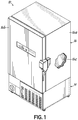
- FIG. 1 an exemplary ultra low temperature freezer according to one embodiment of the present invention is illustrated.
- the unit of FIG. 1 is in the form of an ultra-low temperature freezer ("ULT") 10 having a deck 14 that supports a cabinet 16 thereabove, for storing items that require cooling to temperatures of about -80°C or lower, for example.
- the cabinet 16 in turn, includes a cabinet housing 16a and a door 16b providing access into an interior 16c of the cabinet 16.
- the deck 14 supports one or more components that jointly define a two-stage cascade refrigeration system 20 ( FIG. 2 ) that thermally interacts with cabinet 16 to cool the interior 16c thereof.
- the term "deck” refers to the structural assembly or framework that is located beneath and supports the cabinet 16.
- System 20 is made up of a first stage 24 and a second stage 26 respectively defining first and second circuits for circulating a first refrigerant 34 and a second refrigerant 36.
- a plurality of sensors S 1 through S 18 are arranged to sense different conditions of system 20 and/or properties of the refrigerants 34, 36 in system 20, while a controller 130 accessible through a controller interface 132, permit controlling of the operation of system 20.
- the first stage 24 transfers energy (i.e., heat) from the first refrigerant 34 to the surrounding environment 40, while the second refrigerant 36 of the second stage 26 receives energy from the a cabinet interior 16c. Heat is transferred from the second refrigerant 36 to the first refrigerant 34 through a heat exchanger 44 ( FIG. 5 ) that is in fluid communication with the first and second stages 24, 26 of the refrigeration system 20.
- the first stage 24 includes, in sequence, a first compressor 50, a condenser 54, and a first expansion device 58.
- a fan 62 directs ambient air across the condenser 54 through a filter 54a and facilitates the transfer of heat from the first refrigerant 34 to the surrounding environment 40.
- the second stage 26 includes, also in sequence, a second compressor 70, a second expansion device 74, and an evaporator 78.
- the evaporator 78 is in thermal communication with the interior 16c of cabinet 16 ( FIG. 1 ) such that heat is transferred from the interior 16c to the evaporator 78, thereby cooling the interior 16c.
- the heat exchanger 44 is in fluid communication with the first stage 24 between the first expansion device 58 and the first compressor 50.
- the heat exchanger 44 is in fluid communication with the second stage 26 between the second compressor 70 and the second expansion device 74.
- the first refrigerant 34 is condensed in the condenser 54 and remains in liquid phase until it evaporates at some point within the heat exchanger 44.
- First refrigerant vapor is compressed by first compressor 50 before being returned to condenser 54.
- the second refrigerant 36 receives heat from the interior 16c through the evaporator 78 and flows from the evaporator 78 to the second compressor 70 through a conduit 90.
- An accumulator device 92 is in fluid communication with conduit 90 to pass the second refrigerant 36 in gaseous form to the second compressor 70, while accumulating excessive amounts of the same in liquid form and feeding it to the second compressor 70 at a controlled rate.
- the compressed second refrigerant 36 flows through a conduit 96 and into the heat exchanger 44 thermally communicating the first and second stages 24, 26 with one another.
- the second refrigerant 36 enters the heat exchanger 44 in gas form and transfers heat to the first refrigerant 34 while condensing into a liquid form.
- the flow of the first refrigerant 34 may, for example, be counter-flow relative to the second refrigerant 36, so as to maximize the rate of heat transfer.
- the heat exchanger 44 is in the form of a split-flow brazed plate heat exchanger, vertically oriented within the deck 14 ( FIG. 1 ), and designed to maximize the amount of turbulent flow of the first and second refrigerants 34, 36 within heat exchanger 44, which in turn maximizes the heat transfer from the second refrigerant 36 to the first refrigerant 34.
- Other types or configurations of heat exchangers are possible as well.
- the second refrigerant 36 exits the heat exchanger 44, in liquid form, through an outlet 44a thereof and flows through a conduit 102, through a filter/dryer unit 103, then through the second expansion device 74, and then back to the evaporator 78 of the second stage 26 where it can evaporate into gaseous form while absorbing heat from the cabinet interior 16c.
- the second stage 26 of this exemplary embodiment also includes an oil loop 104 for lubricating the second compressor 70.
- the oil loop 104 includes an oil separator 106 in fluid communication with conduit 96 and an oil return line 108 directing oil back into second compressor 70.
- the second stage 26 may include a de-superheater device 110 to cool down the discharge stream of the second refrigerant 36 and which is in fluid communication with conduit 96 upstream of the heat exchanger 44.
- the first refrigerant 34 flows through the first stage 24. Specifically, the first refrigerant 34 receives heat from the second refrigerant 36 flowing through the heat exchanger 44, leaves the heat exchanger 44 in gas form through an outlet 44b thereof and flows along a pair of conduits 114, 115 towards the first compressor 50.
- An accumulator device 116 is positioned between conduits 114 and 115 to pass the first refrigerant 34 in gaseous form to the first compressor 50, while accumulating excessive amounts of the same in liquid form and feeding it to the first compressor 50 at a controlled rate. From the first compressor 50, the compressed first refrigerant 34 flows through a conduit 118 and into the condenser 54.
- the first refrigerant 34 in condenser 54 transfers heat to the surrounding environment 40 as it condenses from gaseous to liquid form, before flowing along conduits 122, 123, through a filter/dryer unit 126, and into the first expansion device 58 , where the first refrigerant 34 undergoes a pressure drop. From the first expansion device 58, the first refrigerant 34 flows though a conduit 127 back into the heat exchanger 44, entering the same in liquid form.
- an exemplary insulated enclosure 150 supported within the deck 14 encloses one or more of the components described above, permitting sufficient insulation of those components which, in turn, improves the efficiency of the system 20 relative to conventional refrigeration systems.
- the heat exchanger 44 is supported within the insulated enclosure 150 and is surrounded by sufficient amounts of insulation 152 so as to enable attainment of a desired level of efficiency of the heat exchanger 44.
- a plurality of isolators 154 such as foam blocks, prevents contact between conduits within enclosure 150 in selected locations and positions the conduits and other components when the enclosure 150 is being foamed.
- the heat exchanger 44 is oriented generally vertically and further such that the first refrigerant 34 flows in a generally upward direction while the second refrigerant 36 flows in a generally downward direction. More specifically, the first refrigerant 34 enters the heat exchanger 44 proximate a lower portion thereof and exits the same proximate an upper portion of the heat exchanger 44. Similarly, the second refrigerant 36 enters the heat exchanger 44 proximate an upper portion thereof and exits the same proximate a lower portion of the heat exchanger 44. As discussed above, the first refrigerant 34 evaporates from a liquid to a gaseous form in heat exchanger 44, while the second refrigerant 36 condenses from a gaseous to a liquid form in heat exchanger 44.
- the insulated enclosure 150 supports within its interior the first expansion device 58 of the first stage 24.
- the first expansion device 58 is in the form of a capillary tube, although it is contemplated that it could instead take another form such as, and without limitation, an expansion valve (not shown).
- the accumulator device 116 of the first stage 24 is also supported within the interior of insulated enclosure 150, as is the filter/dryer unit 103 of the second stage 26.
- Those of ordinary skill in the art will readily appreciate that other components of system 20 may be located inside the insulated enclosure 150 alternatively or in addition to those components located inside the enclosure 150 in the illustrated embodiment.
- the expecting operating temperature of the specific component under steady state operating conditions taking into account the boiling points and other characteristics of first refrigerant 34 and second refrigerant 36, the desired temperature at which cabinet interior 16c is to be maintained, various operating pressures and similar factors.
- the heat exchanger 44 is expected to operate under steady state conditions at about -40 °C.
- Exemplary refrigerants suitable for the presently described embodiments include refrigerants commercially available under the respective designations R404A for the first refrigerant 34, and a mixture of R290 and R508B for the second refrigerant 36.
- the first and second refrigerants may be combined with an oil to facilitate lubrication of the respective compressors 50, 70.
- the first refrigerant 34 may be combined with Mobil EAL Artic 32 oil and the second refrigerant 36 may be combined with Zerol 150 Alkylbenzene oil.
- the precise arrangement of the components illustrated in the figures is intended to be merely exemplary rather than limiting.
- the heat exchanger 44 of the embodiment of FIGS. 2-5 is located within the deck 14, and more specifically within the insulated enclosure 150.
- One exemplary heat exchanger suitable for use in the present invention is the Model #B3-C30-14-30-HQ-Q1Q2Q3(H1/4D)/Q4 (H38D) brazed plate heat exchanger commercially available from Danfoss A/S of Nordborgvej, Denmark.
- the heat exchanger 44 illustrated in the figures is arranged such that a plurality of generally parallel streams 34a of the first refrigerant 34 and a plurality of generally parallel streams 36a of the second refrigerant 36 are directed through the heat exchanger 44, in counter-flow fashion, to permit the exchange of heat between the first and second refrigerants 34, 36, as illustrated in FIG. 6 .
- the exemplary heat exchanger 44 is in the form of a split-flow, brazed plate heat exchanger that includes a plurality of stacked flat plates 160 that are spaced from one another and each having on one or both of its planar surfaces a series of channels 160a.
- Each of the respective volumes between adjacent plates 160 defines a chamber 164, 166, within which one of the refrigerants 34, 36 flows. Further, the chambers 164, 166 are arranged in alternating fashion i.e., such that two adjacent chambers 164, 166 respectively receive the flow of two different refrigerants 34, 36. Under normal conditions, it is expected that each channel 164 will have liquid first refrigerant 34 adjacent to its base which evaporates as first refrigerant 34 moves upwardly. Under normal conditions, it is expect that each channel 166 will have gaseous second refrigerant 36 adjacent to is top which condenses as second refrigerant 36 moves downwardly.
- the levels for liquid refrigerant and for mixed liquid/gas refrigerant may vary between channels 164 and channels 166 and may also vary among parallel channels 164 and among parallel channels 166. Controls (not shown) can be used to minimize the situations in which particular channels 164 or 166 are occupied either entirely gaseous refrigerant or entirely by liquid refrigerant, except during start-up of the system.
- the shapes of the channels 160a on the plates 160 are chosen so as to facilitate the generation of turbulent flow within the heat exchanger 44, which in turn maximizes the level of heat transfer between the refrigerants 34, 36.
- the channels 160a may be chevron-shaped or be formed as pleats of corrugated plates.
- the term "split-flow" heat exchanger refers to a heat exchanger that splits at least one of the first or second refrigerant streams from a single stream into a plurality of streams that are eventually rejoined into a single fluid stream.
- exemplary heat exchanger 44 is arranged to receive there through respective pluralities of streams of the first and second refrigerants 34, 36
- a different type of split-flow heat exchanger 44 may be arranged such that only one of the refrigerants 34 or 36 may flow in multiple streams relative to the other refrigerant 36 or 34, respectively.
- alternative split-flow heat exchangers 44 may take the form of tube-and-shell heat exchangers, fin-plate heat exchangers, or other types of heat exchangers arranged to permit the flow of at least one of the refrigerants 34, 36 in a plurality of streams in a counter-flow, cross-flow, or parallel-flow arrangement.
- any of these alternative types of heat exchangers 44 is deemed to fall within the scope of the present disclosure.
- the exemplary heat exchanger 44 illustrated in FIG. 6 permits the flow of multiple streams of the first refrigerant 34 that are generally parallel to one another, and the flow of multiple streams of the second refrigerant 36 that are also parallel to one another. This type of flow within the split-flow heat exchanger 44 is intended to be exemplary rather than limiting.
Landscapes
- Engineering & Computer Science (AREA)
- Physics & Mathematics (AREA)
- Mechanical Engineering (AREA)
- Thermal Sciences (AREA)
- General Engineering & Computer Science (AREA)
- Chemical & Material Sciences (AREA)
- Combustion & Propulsion (AREA)
- Devices That Are Associated With Refrigeration Equipment (AREA)
- Heat-Exchange Devices With Radiators And Conduit Assemblies (AREA)
- Details Of Heat-Exchange And Heat-Transfer (AREA)
Description
- The present invention relates generally to refrigeration systems and, more particularly, to refrigeration systems for use with ultra-low temperature freezers.
- Refrigeration systems are known for use with freezers of the type known as "ultra-low temperature freezers" ("ULT's"), which are used to cool their interior storage spaces to relative low temperatures such as about -80°C or lower, for example.
- Known refrigeration systems of this type include two stages circulating respective first and second refrigerants. The first stage transfers energy (i.e., heat) from the first refrigerant to the surrounding environment through a condenser, while the second refrigerant of the second stage receives energy from the cooled space (e.g., a cabinet interior) through an evaporator. Heat is transferred from the second refrigerant to the first refrigerant through a heat exchanger that is in fluid communication with the two stages of the refrigeration system.
- In refrigeration systems of the type described above, the heat exchanger may be of a single-pass, coiled type. Heat exchangers of this type, however, typically occupy large spaces to permit the desired type of heat exchange between the refrigerants. The space and orientation requirements for these heat exchangers force designers to place them alongside or behind the walls of the inner freezer chamber, in front of the outer freezer cabinet, typically taking up valuable cooling/storage space thus not available for cooling.
- In addition to the above, the attainable efficiency of these heat exchangers is limited by the relatively small amount of insulation that can be arranged around them between the walls of the inner freezer chamber and the outer freezer cabinet. Specifically, a relative small amount of insulation is placed around a heat exchanger of a refrigeration system of this type in order to minimize the amount of cooling/storage space that is lost to the heat exchanger.
-
US2402921 (NORMAN SHARPE) relates generally to apparatus for freezing comestibles, but is directed more particularly to apparatus wherein a two stage refrigerating system is used in combination with an improved type of combination condenser and evaporator or condenser and precooling coil. -
WO2009/062839 (SWEP INT AB [SE]; et al) relates to an evaporator unit for exchanging heat between a refrigerant and a low temperature heat source, comprises: a heat exchanger pack including a number of identical heat exchanger plates arranged such that spaces are formed between pairs of said plates, wherein neighboring spaces are separated such that a heat exchange can take place between the refrigerant and the low temperature heat source flowing in such neighboring spaces, and a suction gas heat exchanger exchanging heat between refrigerant about to enter a throttling and refrigerant exiting the heat exchanger pack, wherein the suction gas heat exchanger comprises plates) provided with ridges and grooves or nipples and dimples, wherein the heat exchanger pack and the suction gas heat exchanger are combined into a single unit. -
GB2180921 -
JPS4861447U -
JP2008096085 -
US 6053238 (IBM [US]) describes a cold plate that includes two flow-wise isolated coolant (or refrigerant) passages (or sets of passages) originating at the center of the cold plate and terminating at an edge for use in conjunction with separate refrigeration systems. The cold plate passages are centrally fed by the refrigeration system to create a cooling gradient radiating from the center of the cold plate to its edges. The center-fed cold plate provides a more even temperature gradient across the thermal source. The cold plate passages do not permit flow communication between distinct coolant (or refrigerant) paths. This permits two distinct cooling systems to operate either dually or in a redundant manner. Nonetheless, flow isolation is achieved while still maintaining tight thermal coupling between each path and the object, such as an electronic computer processor module, to be cooled.US 2004/0118139 A1 describes an ultra low temperature freezer with a refrigerated cabinet supported above a deck and comprising a cascade refrigeration system. -
EP 2019276 A1 describes an ultra-low temperature freezer. - There is a need, therefore, for refrigeration systems for use with ultra-low temperature freezers that can operate with a relative large efficiency, and which permit maximization of the cooling/storage space of the freezer.
- In one embodiment, a refrigeration system is provided for use with an ultra-low temperature freezer having a deck and a refrigerated cabinet supported above the deck. The system has a first refrigeration stage and a second refrigeration stage. The first stage defines a first fluid circuit for circulating a first refrigerant. The first stage has a first compressor, a condenser, and a first expansion device that is in fluid communication with the first fluid circuit. The second stage defines a second fluid circuit for circulating a second refrigerant. The second stage has a second compressor, a second expansion device, and an evaporator that is in fluid communication with the second fluid circuit. The system includes an insulated enclosure supported within the deck and a split-flow heat exchanger that is in fluid communication with the first and second fluid circuits and which is located within the insulated enclosure.
- In one embodiment, the heat exchanger may have a plurality of stacked plates that define flow paths for the first and second refrigerants through the heat exchanger. In a specific embodiment, the heat exchanger is in the form of a brazed plate heat exchanger. The heat exchanger may be oriented within the insulated enclosure such that a longitudinal dimension thereof is oriented generally vertical. The first refrigerant may enter the heat exchanger proximate a lower portion thereof and exit the heat exchanger proximate an upper portion thereof, such that the first refrigerant flows generally in an upward direction within the heat exchanger. Additionally, or alternatively, the second refrigerant may enter the heat exchanger proximate an upper portion thereof and exit the heat exchanger proximate a lower portion thereof, such that the second refrigerant flows generally in a downward direction within the heat exchanger.
- In specific embodiments, the heat exchanger is of a counter-flow type. Also, the first expansion device may be located within the insulated enclosure. Additionally, the first expansion device may include at least one of a capillary tube or a valve. The first refrigeration stage may have a first accumulator that is in fluid communication with the first fluid circuit. The first accumulator may, for example, be located within the insulated enclosure. The first refrigeration stage may have a first filter/dryer that is in fluid communication with the first fluid circuit and which is supported within the deck. The first filter/dryer is, in some embodiments, located outside of the insulated enclosure. The second expansion device may be located outside the insulated enclosure. Additionally or alternatively, the second expansion device may include at least one of a capillary tube or a valve. The second refrigeration stage, in specific embodiments, has a second accumulator that is in fluid communication with a second fluid circuit. The second accumulator may, for example, be located outside of the insulated enclosure. Alternatively, the second accumulator may be located inside the insulated enclosure.
- In another embodiment, a refrigeration system is provided for use with an ultra-low temperature freezer having a deck and a refrigerated cabinet supported above the deck. The system includes a first refrigeration stage and a second refrigeration stage. The first stage defines a first fluid circuit for circulating a first refrigerant, with the first stage having a first compressor, a condenser, a first filter/dryer, a first expansion device, and a first accumulator that is in fluid communication with the first fluid circuit. The second stage defines a second fluid circuit for circulating a second refrigerant, and has a second compressor, a second filter/dryer, a second expansion device, an evaporator, and a second accumulator that is in fluid communication with the second fluid circuit. The system also includes an insulated enclosure that is supported within the deck, and a split-flow heat exchanger that is in fluid communication with the first and second fluid circuits. The heat exchanger, the expansion device, the first accumulator, and the second filter/dryer are located within the insulated enclosure.
- In yet another embodiment, an ultra-low temperature freezer is provided having a deck, a refrigerated cabinet supported above the deck, and a refrigeration system that is in thermal communication with the refrigerated cabinet. The refrigeration system includes a first refrigeration stage defining a first fluid circuit for circulating the first refrigerant, with the first stage having a first compressor, a condenser, and a first expansion device that is in fluid communication with the first fluid circuit. The system also includes a second refrigeration stage that defines a second fluid circuit for circulating a second refrigerant, with the second stage having a second compressor, a second expansion device, and an evaporator that is in fluid communication with the second fluid circuit. An insulated enclosure of the refrigeration system is supported within the deck, and a split-flow heat exchanger is in fluid communication with the first and second fluid circuits and is located within the insulated enclosure.
- In another embodiment, a method is provided for operating an ultra-low temperature freezer. The method includes circulating a first refrigerant through a first compressor, a condenser, and a first expansion device of a first stage of a refrigeration system. A second refrigerant is circulated through a second compressor, a second expansion device, and an evaporator of a second stage of the system. A stream of at least one of the first or second refrigerants is split within a deck of the freezer into a plurality of streams that are arranged relative to one or more streams of the other of the first or second refrigerants so as to exchange heat between the first and second refrigerants. The method includes rejoining the plurality of streams and supporting a refrigerated cabinet of the freezer above the deck.
- The method, in a specific embodiment, includes directing the stream of the at least one of the first or second refrigerants along a plurality of generally parallel streams. The method may be such that splitting the stream of the at least one of the first or second refrigerants includes turbulently flowing the at least one of the first or second refrigerants. Additionally or alternatively, splitting the stream of the at least one of the first or second refrigerants includes directing the at least one of the first or second refrigerants along a plurality of parallel plates that are spaced from one another. The method may include flowing the first refrigerant in a generally upward direction and/or flowing the second refrigerant in a generally downward direction.
- In a specific embodiment, the method includes accumulating a liquid form of the first refrigerant or a liquid form of the second refrigerant within an insulated enclosure that concurrently insulates the plurality of streams. The method may include expanding the first refrigerant or the second refrigerant within one of a valve or a capillary tube.
- Accordingly, the system and related methods described herein, by having a heat exchanger in the deck of the freezer, allows the positioning of adequate quantities of insulation around the heat exchanger, thereby attaining higher efficiencies than observed with conventional ultra-low temperature freezers. Moreover, having the heat exchanger in the deck of the freezer allows for maximization of the cabinet interior space above the deck.
- The accompanying drawings, which are incorporated in and constitute a part of this specification, illustrate embodiments of the invention and, together with a general description of the invention given above, and the detailed description of the embodiments given below, serve to explain the principles of the invention.
-
FIG. 1 is a partially broken perspective view of an ultra-low temperature freezer in accordance with an embodiment of the invention. -
FIG. 2 is a schematic representation of the refrigeration system used with the freezer ofFIG. 1 . -
FIG. 3 is a perspective view of a deck of the freezer ofFIG. 1 . -
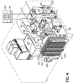
FIG. 4 is a perspective view illustrating an interior portion of the deck ofFIG. 2 . -
FIG. 5 is a perspective view of an interior portion of an insulated enclosure within the deck ofFIGS. 2-3 . -
FIG. 6 is a schematic, disassembled view illustrating the flow of first and second refrigerants through an exemplary heat exchanger of the system ofFIG. 2 . - With reference to the figures, and more specifically to
FIG. 1 , an exemplary ultra low temperature freezer according to one embodiment of the present invention is illustrated. The unit ofFIG. 1 is in the form of an ultra-low temperature freezer ("ULT") 10 having adeck 14 that supports acabinet 16 thereabove, for storing items that require cooling to temperatures of about -80°C or lower, for example. Thecabinet 16, in turn, includes acabinet housing 16a and adoor 16b providing access into an interior 16c of thecabinet 16. Thedeck 14 supports one or more components that jointly define a two-stage cascade refrigeration system 20 (FIG. 2 ) that thermally interacts withcabinet 16 to cool the interior 16c thereof. As used herein, the term "deck" refers to the structural assembly or framework that is located beneath and supports thecabinet 16. An exemplary refrigeration system similar tosystem 20 is described inU.S. Patent Application Serial No. 12/570,348 , entitled REFRIGERATION SYSTEM HAVING A VARIABLE SPEED COMPRESSOR (Attorney Docket TFLED-226AUS), assigned to the assignee of the present application, and filed concurrently herewith. The disclosure of this commonly-assigned application is incorporated by reference herein in its entirety. - With reference to
FIGS. 2-5 , details of theexemplary refrigeration system 20 are illustrated.System 20 is made up of afirst stage 24 and asecond stage 26 respectively defining first and second circuits for circulating afirst refrigerant 34 and asecond refrigerant 36. A plurality of sensors S1 through S18 are arranged to sense different conditions ofsystem 20 and/or properties of therefrigerants system 20, while acontroller 130 accessible through acontroller interface 132, permit controlling of the operation ofsystem 20. Thefirst stage 24 transfers energy (i.e., heat) from the first refrigerant 34 to the surroundingenvironment 40, while thesecond refrigerant 36 of thesecond stage 26 receives energy from the a cabinet interior 16c. Heat is transferred from the second refrigerant 36 to the first refrigerant 34 through a heat exchanger 44 (FIG. 5 ) that is in fluid communication with the first andsecond stages refrigeration system 20. - The
first stage 24 includes, in sequence, afirst compressor 50, acondenser 54, and afirst expansion device 58. Afan 62 directs ambient air across thecondenser 54 through a filter 54a and facilitates the transfer of heat from the first refrigerant 34 to the surroundingenvironment 40. Thesecond stage 26 includes, also in sequence, asecond compressor 70, asecond expansion device 74, and anevaporator 78. Theevaporator 78 is in thermal communication with the interior 16c of cabinet 16 (FIG. 1 ) such that heat is transferred from the interior 16c to theevaporator 78, thereby cooling the interior 16c. Theheat exchanger 44 is in fluid communication with thefirst stage 24 between thefirst expansion device 58 and thefirst compressor 50. Further, theheat exchanger 44 is in fluid communication with thesecond stage 26 between thesecond compressor 70 and thesecond expansion device 74. In general, thefirst refrigerant 34 is condensed in thecondenser 54 and remains in liquid phase until it evaporates at some point within theheat exchanger 44. First refrigerant vapor is compressed byfirst compressor 50 before being returned tocondenser 54. - In operation, the
second refrigerant 36 receives heat from the interior 16c through theevaporator 78 and flows from theevaporator 78 to thesecond compressor 70 through aconduit 90. Anaccumulator device 92 is in fluid communication withconduit 90 to pass the second refrigerant 36 in gaseous form to thesecond compressor 70, while accumulating excessive amounts of the same in liquid form and feeding it to thesecond compressor 70 at a controlled rate. From thesecond compressor 70, the compressed second refrigerant 36 flows through aconduit 96 and into theheat exchanger 44 thermally communicating the first andsecond stages second refrigerant 36 enters theheat exchanger 44 in gas form and transfers heat to the first refrigerant 34 while condensing into a liquid form. In this regard, the flow of the first refrigerant 34 may, for example, be counter-flow relative to thesecond refrigerant 36, so as to maximize the rate of heat transfer. In one specific, non-limiting example, theheat exchanger 44 is in the form of a split-flow brazed plate heat exchanger, vertically oriented within the deck 14 (FIG. 1 ), and designed to maximize the amount of turbulent flow of the first andsecond refrigerants heat exchanger 44, which in turn maximizes the heat transfer from the second refrigerant 36 to thefirst refrigerant 34. Other types or configurations of heat exchangers are possible as well. - With continued reference to
FIGS. 2-5 , the second refrigerant 36 exits theheat exchanger 44, in liquid form, through anoutlet 44a thereof and flows through aconduit 102, through a filter/dryer unit 103, then through thesecond expansion device 74, and then back to theevaporator 78 of thesecond stage 26 where it can evaporate into gaseous form while absorbing heat from the cabinet interior 16c. Thesecond stage 26 of this exemplary embodiment also includes anoil loop 104 for lubricating thesecond compressor 70. Specifically, theoil loop 104 includes anoil separator 106 in fluid communication withconduit 96 and anoil return line 108 directing oil back intosecond compressor 70. Additionally, or alternatively, thesecond stage 26 may include ade-superheater device 110 to cool down the discharge stream of thesecond refrigerant 36 and which is in fluid communication withconduit 96 upstream of theheat exchanger 44. - As discussed above, the first refrigerant 34 flows through the
first stage 24. Specifically, thefirst refrigerant 34 receives heat from the second refrigerant 36 flowing through theheat exchanger 44, leaves theheat exchanger 44 in gas form through an outlet 44b thereof and flows along a pair ofconduits first compressor 50. Anaccumulator device 116 is positioned betweenconduits first compressor 50, while accumulating excessive amounts of the same in liquid form and feeding it to thefirst compressor 50 at a controlled rate. From thefirst compressor 50, the compressed first refrigerant 34 flows through aconduit 118 and into thecondenser 54. The first refrigerant 34 incondenser 54 transfers heat to the surroundingenvironment 40 as it condenses from gaseous to liquid form, before flowing alongconduits dryer unit 126, and into thefirst expansion device 58 , where thefirst refrigerant 34 undergoes a pressure drop. From thefirst expansion device 58, the first refrigerant 34 flows though aconduit 127 back into theheat exchanger 44, entering the same in liquid form. - With continued reference to
FIGS. 2-5 , an exemplaryinsulated enclosure 150 supported within thedeck 14 encloses one or more of the components described above, permitting sufficient insulation of those components which, in turn, improves the efficiency of thesystem 20 relative to conventional refrigeration systems. Specifically, theheat exchanger 44 is supported within theinsulated enclosure 150 and is surrounded by sufficient amounts ofinsulation 152 so as to enable attainment of a desired level of efficiency of theheat exchanger 44. Moreover, a plurality ofisolators 154, such as foam blocks, prevents contact between conduits withinenclosure 150 in selected locations and positions the conduits and other components when theenclosure 150 is being foamed. - In this exemplary embodiment, the
heat exchanger 44 is oriented generally vertically and further such that the first refrigerant 34 flows in a generally upward direction while the second refrigerant 36 flows in a generally downward direction. More specifically, thefirst refrigerant 34 enters theheat exchanger 44 proximate a lower portion thereof and exits the same proximate an upper portion of theheat exchanger 44. Similarly, thesecond refrigerant 36 enters theheat exchanger 44 proximate an upper portion thereof and exits the same proximate a lower portion of theheat exchanger 44. As discussed above, thefirst refrigerant 34 evaporates from a liquid to a gaseous form inheat exchanger 44, while thesecond refrigerant 36 condenses from a gaseous to a liquid form inheat exchanger 44. - In the exemplary embodiment of
FIGS. 2-5 , moreover, theinsulated enclosure 150 supports within its interior thefirst expansion device 58 of thefirst stage 24. In this embodiment, thefirst expansion device 58 is in the form of a capillary tube, although it is contemplated that it could instead take another form such as, and without limitation, an expansion valve (not shown). In addition to thefirst expansion device 58, theaccumulator device 116 of thefirst stage 24 is also supported within the interior ofinsulated enclosure 150, as is the filter/dryer unit 103 of thesecond stage 26. Those of ordinary skill in the art will readily appreciate that other components ofsystem 20 may be located inside theinsulated enclosure 150 alternatively or in addition to those components located inside theenclosure 150 in the illustrated embodiment. - Among the factors which one skilled in the art can use in deciding which components to include within
enclosure 150 are the expecting operating temperature of the specific component under steady state operating conditions, taking into account the boiling points and other characteristics of first refrigerant 34 and second refrigerant 36, the desired temperature at which cabinet interior 16c is to be maintained, various operating pressures and similar factors. For example, in ULT freezers with an expected cabinet temperature of about -86 °C and certain common refrigerants, theheat exchanger 44 is expected to operate under steady state conditions at about
-40 °C. Exemplary refrigerants suitable for the presently described embodiments include refrigerants commercially available under the respective designations R404A for thefirst refrigerant 34, and a mixture of R290 and R508B for thesecond refrigerant 36. Moreover, in specific embodiments, the first and second refrigerants may be combined with an oil to facilitate lubrication of therespective compressors Zerol 150 Alkylbenzene oil. In another aspect of the present disclosure, the precise arrangement of the components illustrated in the figures is intended to be merely exemplary rather than limiting. - As discussed above, the
heat exchanger 44 of the embodiment ofFIGS. 2-5 is located within thedeck 14, and more specifically within theinsulated enclosure 150. One exemplary heat exchanger suitable for use in the present invention is the Model #B3-C30-14-30-HQ-Q1Q2Q3(H1/4D)/Q4 (H38D) brazed plate heat exchanger commercially available from Danfoss A/S of Nordborgvej, Denmark. Theheat exchanger 44 illustrated in the figures is arranged such that a plurality of generallyparallel streams 34a of thefirst refrigerant 34 and a plurality of generally parallel streams 36a of the second refrigerant 36 are directed through theheat exchanger 44, in counter-flow fashion, to permit the exchange of heat between the first andsecond refrigerants FIG. 6 . To this end, theexemplary heat exchanger 44 is in the form of a split-flow, brazed plate heat exchanger that includes a plurality of stackedflat plates 160 that are spaced from one another and each having on one or both of its planar surfaces a series ofchannels 160a. - Each of the respective volumes between
adjacent plates 160 defines achamber refrigerants chambers adjacent chambers different refrigerants channel 164 will have liquid first refrigerant 34 adjacent to its base which evaporates as first refrigerant 34 moves upwardly. Under normal conditions, it is expect that eachchannel 166 will have gaseous second refrigerant 36 adjacent to is top which condenses as second refrigerant 36 moves downwardly. The levels for liquid refrigerant and for mixed liquid/gas refrigerant may vary betweenchannels 164 andchannels 166 and may also vary amongparallel channels 164 and amongparallel channels 166. Controls (not shown) can be used to minimize the situations in whichparticular channels - In one aspect of the
exemplary heat exchanger 44, the shapes of thechannels 160a on theplates 160 are chosen so as to facilitate the generation of turbulent flow within theheat exchanger 44, which in turn maximizes the level of heat transfer between therefrigerants channels 160a may be chevron-shaped or be formed as pleats of corrugated plates. As used herein, the term "split-flow" heat exchanger refers to a heat exchanger that splits at least one of the first or second refrigerant streams from a single stream into a plurality of streams that are eventually rejoined into a single fluid stream. - While the
exemplary heat exchanger 44 is arranged to receive there through respective pluralities of streams of the first andsecond refrigerants flow heat exchanger 44 may be arranged such that only one of therefrigerants flow heat exchangers 44 may take the form of tube-and-shell heat exchangers, fin-plate heat exchangers, or other types of heat exchangers arranged to permit the flow of at least one of therefrigerants heat exchangers 44 is deemed to fall within the scope of the present disclosure. Further, theexemplary heat exchanger 44 illustrated inFIG. 6 permits the flow of multiple streams of the first refrigerant 34 that are generally parallel to one another, and the flow of multiple streams of the second refrigerant 36 that are also parallel to one another. This type of flow within the split-flow heat exchanger 44 is intended to be exemplary rather than limiting. - While the present invention has been illustrated by a description of various embodiments and while these embodiments have been described in considerable detail, it is not the intention of the applicant to restrict or in any way limit the scope of the appended claims to such detail.
Claims (17)
- An ultra-low temperature freezer (10) having a deck (14), a refrigerated cabinet (16) for storing items that require cooling which is supported above the deck (14), and a refrigeration system (20), the refrigeration system (20) comprising:a first refrigeration stage (24) defining a first fluid circuit for circulating a first refrigerant (34), the first refrigeration stage (24) having a first compressor (50), a condenser (54), and a first expansion device (58) in fluid communication with the first fluid circuit;a second refrigeration stage (26) defining a second fluid circuit for circulating a second refrigerant (36), the second refrigeration stage having a second compressor (70), a second expansion device (74) and an evaporator (78) in fluid communication with the second fluid circuit, characterized by:an insulated enclosure (150) supported within the deck (14); anda split-flow heat exchanger (44) in fluid communication with the first and second fluid circuits and being located within the insulated enclosure (150).
- The ultra-low temperature freezer (10) of claim 1, wherein the split-flow heat exchanger (44) comprises a plurality of stacked plates (160) that define flow paths for the first and second refrigerants (34, 36) through the heat exchanger (44).
- The ultra-low temperature freezer (10) of claim 2, wherein the heat exchanger (44) comprises a brazed plate heat exchanger.
- The ultra-low temperature freezer (10) of any of the preceding claims, wherein a longitudinal dimension of the split-flow heat exchanger (44) is oriented vertically within the insulated enclosure (150).
- The ultra-low temperature freezer (10) of any of the preceding claims, wherein the first refrigerant (34) enters the split-flow heat exchanger (44) proximate a lower portion thereof and exits the split-flow heat exchanger (44) proximate an upper portion thereof so that the first refrigerant (34) flows generally in an upward direction within the split-flow heat exchanger (44).
- The ultra-low temperature freezer (10) of any of the preceding claims, wherein the second refrigerant (36) enters the split-flow heat exchanger (44) proximate an upper portion thereof and exits the split-flow heat exchanger (44) proximate a lower portion thereof so that the second refrigerant (36) flows generally in a downward direction within the split-flow heat exchanger (44).
- The ultra-low temperature freezer (10) of any of the preceding claims, wherein the split-flow heat exchanger (44) is of a counter-flow type.
- The ultra-low temperature freezer (10) of any of the preceding claims, wherein the first expansion device (58) is located within the insulated enclosure (150).
- The ultra-low temperature freezer (10) of any of the preceding claims, wherein the first refrigeration stage (24) further has a first accumulator (116) in fluid communication with the first fluid circuit with the first accumulator (116) being located within the insulated enclosure (150).
- A method of operating an ultra-low temperature freezer (10) having a deck, a refrigerated cabinet (16) for storing items that require cooling which is supported above the deck (14), and an insulated enclosure within the deck (14), the method comprising:circulating a first refrigerant (34) through a first compressor (50), a condenser (54), and a first expansion device (58) of a first stage (24) of a refrigeration system (20);circulating a second refrigerant (36) through a second compressor (70), a second expansion device (74), and an evaporator (78) of a second stage (26) of the refrigeration system (20), andsplitting within the insulated enclosure in the deck (14) of the freezer (10) a stream of at least one of the first or second refrigerants (34, 36) into a plurality of streams (34a, 36a) arranged relative to one or more streams of the other of the first or second refrigerants (34a, 36a) so as to exchange heat between the first and second refrigerants (34, 36).
- The method of claim 10, wherein splitting the stream of the at least one of the first or second refrigerants (34, 36) includes directing the at least one of the first or second refrigerants (34, 36) along a plurality of generally parallel streams (34a, 36a).
- The method of claim 10, wherein splitting the stream of the at least one of the first or second refrigerants (34, 36) includes turbulently flowing the at least one of the first or second refrigerants (34, 36).
- The method of claim 10, further comprising:
splitting respective streams of the first and second refrigerants (34, 36) along respective first and second pluralities of streams (34a, 36a), the first and second pluralities (34a, 36a) being arranged relative to one another so as to exchange heat between the first and second refrigerants (34, 36). - The method of any of claims 10-12, wherein splitting of the stream of the at least one of the first or second refrigerants (34, 36) includes directing the at least one of the first or second refrigerants (34, 36) along a plurality of parallel plates (160) that are spaced from one another.
- The method of any of claims 10-12, wherein splitting the stream of the at least one of the first or second refrigerants (34, 36) includes flowing the first refrigerant (34) in a generally upward direction.
- The method of any of claims 10-12, wherein splitting the stream of the at least one of the first or second refrigerants (34, 36) includes flowing the second refrigerant (36) in a generally downward direction.
- The method of any of the preceding claims, further comprising:
accumulating a liquid form of the first refrigerant (34) or a liquid form of the second refrigerant (36) within the insulated enclosure (150) .
Applications Claiming Priority (2)
| Application Number | Priority Date | Filing Date | Title |
|---|---|---|---|
| US12/570,480 US8011201B2 (en) | 2009-09-30 | 2009-09-30 | Refrigeration system mounted within a deck |
| PCT/US2010/050694 WO2011041392A2 (en) | 2009-09-30 | 2010-09-29 | Refrigeration system mounted within a deck |
Publications (2)
| Publication Number | Publication Date |
|---|---|
| EP2483609A2 EP2483609A2 (en) | 2012-08-08 |
| EP2483609B1 true EP2483609B1 (en) | 2018-10-31 |
Family
ID=43778780
Family Applications (1)
| Application Number | Title | Priority Date | Filing Date |
|---|---|---|---|
| EP10770663.2A Active EP2483609B1 (en) | 2009-09-30 | 2010-09-29 | Cascade refrigeration system mounted within a deck |
Country Status (6)
| Country | Link |
|---|---|
| US (1) | US8011201B2 (en) |
| EP (1) | EP2483609B1 (en) |
| JP (5) | JP2013506815A (en) |
| CN (1) | CN102713464B (en) |
| DK (1) | DK2483609T3 (en) |
| WO (1) | WO2011041392A2 (en) |
Families Citing this family (17)
| Publication number | Priority date | Publication date | Assignee | Title |
|---|---|---|---|---|
| EP2798284B1 (en) * | 2011-10-07 | 2016-12-14 | Danfoss A/S | Method of coordinating operation of compressors |
| US8925346B2 (en) | 2012-02-07 | 2015-01-06 | Thermo Fisher Scientific (Asheville) Llc | High performance freezer having cylindrical cabinet |
| JP5575192B2 (en) * | 2012-08-06 | 2014-08-20 | 三菱電機株式会社 | Dual refrigeration equipment |
| DE102012221925A1 (en) * | 2012-11-29 | 2014-06-05 | Behr Gmbh & Co. Kg | Heat exchanger |
| US20140250925A1 (en) * | 2013-03-06 | 2014-09-11 | Esco Technologies (Asia) Pte Ltd | Predictive Failure Algorithm For Refrigeration Systems |
| CN103231877B (en) * | 2013-04-03 | 2015-04-01 | 中国科学院理化技术研究所 | Horizontal cold box system |
| DE102013210177A1 (en) * | 2013-05-31 | 2014-12-04 | Siemens Aktiengesellschaft | Cooling system and cooling process for use in high-temperature environments |
| US9372018B2 (en) * | 2013-06-05 | 2016-06-21 | Hamilton Sundstrand Corporation | Evaporator heat exchanger |
| US9657969B2 (en) * | 2013-12-30 | 2017-05-23 | Rolls-Royce Corporation | Multi-evaporator trans-critical cooling systems |
| CN106133407B (en) * | 2014-03-26 | 2018-10-02 | 舍弗勒技术股份两合公司 | Single motor transmission actuator and control method thereof |
| WO2016089401A1 (en) * | 2014-12-04 | 2016-06-09 | United Technologies Corporation | Field-active heat pumping using liquid materials |
| CN104613708A (en) * | 2015-01-05 | 2015-05-13 | 金俊三 | Overall refrigerating unit of refrigerator |
| CN105015939A (en) * | 2015-07-03 | 2015-11-04 | 青岛澳柯玛超低温冷冻设备有限公司 | Low-temperature freezer |
| EP3517874B1 (en) * | 2018-01-29 | 2023-09-13 | Valeo Autosystemy SP. Z.O.O. | Heat exchanging module having a housing comprising an inner frame and an outer frame |
| JP7393543B2 (en) | 2020-06-04 | 2023-12-06 | Phcホールディングス株式会社 | dual refrigeration equipment |
| CN117091321A (en) * | 2023-08-29 | 2023-11-21 | 英诺绿能技术(河南)有限公司 | A recirculating heat pump system |
| CN119665523B (en) * | 2025-02-19 | 2025-06-17 | 浙江博开机电科技有限公司 | Ultralow-temperature efficient refrigerating device |
Citations (3)
| Publication number | Priority date | Publication date | Assignee | Title |
|---|---|---|---|---|
| US6053238A (en) * | 1998-10-30 | 2000-04-25 | International Business Machines Corporation | Center feed parallel flow cold plate for dual refrigeration systems |
| JP2008096085A (en) * | 2006-10-16 | 2008-04-24 | Hoshizaki Electric Co Ltd | Cooling apparatus |
| EP2019276A1 (en) * | 2006-05-15 | 2009-01-28 | Sanyo Electric Co., Ltd. | Freezing device |
Family Cites Families (82)
| Publication number | Priority date | Publication date | Assignee | Title |
|---|---|---|---|---|
| US2402921A (en) | 1942-08-18 | 1946-06-25 | Sharpe Norman | Apparatus for freezing comestibles |
| US2462279A (en) | 1945-09-27 | 1949-02-22 | S F Bowser & Company Ltd | Multiple compartment refrigerator, including controls for the refrigerating system thereof |
| NL125884C (en) | 1965-04-08 | |||
| JPS527885Y2 (en) * | 1972-05-30 | 1977-02-18 | ||
| US3775995A (en) | 1972-07-17 | 1973-12-04 | Westinghouse Electric Corp | Variable capacity multiple compressor refrigeration system |
| US4102149A (en) | 1977-04-22 | 1978-07-25 | Westinghouse Electric Corp. | Variable capacity multiple compressor refrigeration system |
| IL55032A (en) * | 1978-06-29 | 1984-05-31 | Stolov Michael | Color picture display system including electronically controlled slides |
| US4679411A (en) | 1978-08-16 | 1987-07-14 | American Standard Inc. | Stepped capacity constant volume building air conditioning system |
| US5079929A (en) | 1979-07-31 | 1992-01-14 | Alsenz Richard H | Multi-stage refrigeration apparatus and method |
| US5265434A (en) | 1979-07-31 | 1993-11-30 | Alsenz Richard H | Method and apparatus for controlling capacity of a multiple-stage cooling system |
| US4951475A (en) | 1979-07-31 | 1990-08-28 | Altech Controls Corp. | Method and apparatus for controlling capacity of a multiple-stage cooling system |
| US4313309A (en) * | 1979-11-23 | 1982-02-02 | Lehman Jr Robert D | Two-stage refrigerator |
| JPS6027352Y2 (en) * | 1980-01-18 | 1985-08-17 | 三洋電機株式会社 | freezer |
| JPS5938656U (en) * | 1982-09-06 | 1984-03-12 | 株式会社東芝 | Ultra-low temperature equipment |
| US4787211A (en) | 1984-07-30 | 1988-11-29 | Copeland Corporation | Refrigeration system |
| JPS6155674U (en) * | 1984-09-17 | 1986-04-14 | ||
| GB2180921B (en) | 1985-09-25 | 1990-01-24 | Sanyo Electric Co | Refrigeration system |
| JP2862609B2 (en) * | 1988-05-25 | 1999-03-03 | アルフアーラヴアル サーマル アーベー | Plate evaporator |
| US5241829A (en) * | 1989-11-02 | 1993-09-07 | Osaka Prefecture Government | Method of operating heat pump |
| US5271238A (en) | 1990-09-14 | 1993-12-21 | Nartron Corporation | Environmental control system |
| US5253483A (en) | 1990-09-14 | 1993-10-19 | Nartron Corporation | Environmental control system |
| US5095712A (en) | 1991-05-03 | 1992-03-17 | Carrier Corporation | Economizer control with variable capacity |
| US5205130A (en) | 1991-07-02 | 1993-04-27 | Pannell Bobby L | Dual stage AC system for recreational vehicle |
| US5203179A (en) | 1992-03-04 | 1993-04-20 | Ecoair Corporation | Control system for an air conditioning/refrigeration system |
| TW224512B (en) * | 1992-03-19 | 1994-06-01 | Mitsubishi Rayon Co | |
| CA2113519C (en) * | 1994-01-14 | 1999-06-08 | Allan K. So | Passive by-pass for heat exchangers |
| JPH0828978A (en) * | 1994-07-15 | 1996-02-02 | Daikin Ind Ltd | Cooling device for dual refrigeration system |
| US5586444A (en) | 1995-04-25 | 1996-12-24 | Tyler Refrigeration | Control for commercial refrigeration system |
| US5694780A (en) | 1995-12-01 | 1997-12-09 | Alsenz; Richard H. | Condensed liquid pump for compressor body cooling |
| US6119472A (en) * | 1996-02-16 | 2000-09-19 | Ross; Harold F. | Ice cream machine optimized to efficiently and evenly freeze ice cream |
| US5927088A (en) | 1996-02-27 | 1999-07-27 | Shaw; David N. | Boosted air source heat pump |
| MY114473A (en) * | 1997-04-08 | 2002-10-31 | Daikin Ind Ltd | Refrigerating system |
| JPH10300330A (en) * | 1997-04-25 | 1998-11-13 | Sanyo Electric Co Ltd | Low temperature storage cabinet |
| US6213194B1 (en) * | 1997-07-16 | 2001-04-10 | International Business Machines Corporation | Hybrid cooling system for electronics module |
| JP3063742B2 (en) | 1998-01-30 | 2000-07-12 | ダイキン工業株式会社 | Refrigeration equipment |
| TW446106U (en) | 1998-02-20 | 2001-07-11 | Matsushita Refrigeration Co Lt | Refrigerator having a cooler mounted in each of a refrigerator compartment and a freezer compartment |
| JP3292128B2 (en) * | 1998-02-27 | 2002-06-17 | ダイキン工業株式会社 | Plate heat exchanger |
| JP3094997B2 (en) * | 1998-09-30 | 2000-10-03 | ダイキン工業株式会社 | Refrigeration equipment |
| JP2000258039A (en) * | 1999-03-08 | 2000-09-22 | Daikin Ind Ltd | Refrigeration equipment for showcases |
| US20010030043A1 (en) * | 1999-05-11 | 2001-10-18 | William T. Gleisle | Brazed plate heat exchanger utilizing metal gaskets and method for making same |
| US6460355B1 (en) * | 1999-08-31 | 2002-10-08 | Guy T. Trieskey | Environmental test chamber fast cool down and heat up system |
| JP2001118134A (en) * | 1999-10-19 | 2001-04-27 | Sanyo Electric Co Ltd | Vending machine |
| KR100388675B1 (en) | 2000-12-18 | 2003-06-25 | 삼성전자주식회사 | Air conditioner having pressure controlling unit and its control method |
| US6494054B1 (en) * | 2001-08-16 | 2002-12-17 | Praxair Technology, Inc. | Multicomponent refrigeration fluid refrigeration system with auxiliary ammonia cascade circuit |
| JP2003106707A (en) * | 2001-09-27 | 2003-04-09 | Sanyo Electric Co Ltd | Water cooling condensing unit |
| DE10224754B4 (en) | 2002-06-04 | 2004-11-25 | Webasto Thermosysteme International Gmbh | Use of a cold store for COP optimization of a refrigeration cycle |
| US6595009B1 (en) * | 2002-07-17 | 2003-07-22 | Praxair Technology, Inc. | Method for providing refrigeration using two circuits with differing multicomponent refrigerants |
| DE10242464B4 (en) * | 2002-09-11 | 2008-04-10 | Webasto Ag | Device for air conditioning a vehicle interior |
| FR2846733B1 (en) * | 2002-10-31 | 2006-09-15 | Valeo Thermique Moteur Sa | CONDENSER, IN PARTICULAR FOR A CIRCUIT FOR CIMATING A MOTOR VEHICLE, AND CIRCUIT COMPRISING THE CONDENSER |
| JP4004391B2 (en) * | 2002-11-29 | 2007-11-07 | 三洋電機株式会社 | Dual refrigeration equipment |
| US6986262B2 (en) | 2002-11-28 | 2006-01-17 | Sanyo Electric Co., Ltd. | Binary refrigeration unit |
| JP2004190917A (en) * | 2002-12-10 | 2004-07-08 | Sanyo Electric Co Ltd | Refrigeration device |
| US6766652B2 (en) | 2002-12-18 | 2004-07-27 | Gsle Development Corporation | Dual independent chamber ultra-low temperature freezer |
| DE10322406A1 (en) * | 2003-05-16 | 2004-12-02 | Api Schmidt-Bretten Gmbh & Co. Kg | Plate heat exchangers |
| US6978793B1 (en) * | 2003-05-21 | 2005-12-27 | Phex Llc | Portable cleaning apparatus and method for single pass plate and frame heat exchangers |
| DE10328746A1 (en) * | 2003-06-25 | 2005-01-13 | Behr Gmbh & Co. Kg | Multi-stage heat exchange apparatus and method of making such apparatus |
| JP2005114194A (en) * | 2003-10-03 | 2005-04-28 | Sanyo Electric Co Ltd | Low temperature storage shed |
| JP4130170B2 (en) * | 2003-11-28 | 2008-08-06 | 三洋電機株式会社 | Cooling storage |
| US7096681B2 (en) | 2004-02-27 | 2006-08-29 | York International Corporation | System and method for variable speed operation of a screw compressor |
| US7231773B2 (en) | 2004-04-12 | 2007-06-19 | York International Corporation | Startup control system and method for a multiple compressor chiller system |
| US7193826B2 (en) | 2004-02-27 | 2007-03-20 | York International Corporation | Motor disconnect arrangement for a variable speed drive |
| US7207183B2 (en) | 2004-04-12 | 2007-04-24 | York International Corp. | System and method for capacity control in a multiple compressor chiller system |
| US7716943B2 (en) | 2004-05-12 | 2010-05-18 | Electro Industries, Inc. | Heating/cooling system |
| KR20070113276A (en) * | 2005-03-18 | 2007-11-28 | 캐리어 코포레이션 | Bottom bottom plate assembly for refrigerated showcases |
| RU2007138610A (en) * | 2005-03-18 | 2009-04-27 | Кэрриэ Копэрейшн (US) | RACK FOR MOUNTING THE EVAPORATOR ASSEMBLY AND THE EVAPORATOR ASSEMBLY (OPTIONS) |
| AU2005329419A1 (en) * | 2005-03-18 | 2006-09-28 | Carrier Corporation | Refrigerated merchandiser |
| US7168262B2 (en) * | 2005-03-24 | 2007-01-30 | Hoshizaki Denki Kabushiki Kaisha | Ice making machine |
| US20060225445A1 (en) | 2005-04-07 | 2006-10-12 | Carrier Corporation | Refrigerant system with variable speed compressor in tandem compressor application |
| US7310953B2 (en) | 2005-11-09 | 2007-12-25 | Emerson Climate Technologies, Inc. | Refrigeration system including thermoelectric module |
| US7337630B2 (en) * | 2005-11-10 | 2008-03-04 | Johnson Controls Technology Company | Compact evaporator for chiller application |
| US20070156032A1 (en) | 2006-01-04 | 2007-07-05 | Gordon Linda S | Electronic disease management system |
| JP5026736B2 (en) * | 2006-05-15 | 2012-09-19 | パナソニックヘルスケア株式会社 | Refrigeration equipment |
| US20070276637A1 (en) | 2006-05-24 | 2007-11-29 | Honeywell International Inc. | Visual optimization programming |
| JP4786443B2 (en) | 2006-07-11 | 2011-10-05 | 株式会社日立産機システム | Compressed air production facility |
| US8327656B2 (en) | 2006-08-15 | 2012-12-11 | American Power Conversion Corporation | Method and apparatus for cooling |
| US8042355B2 (en) | 2006-12-28 | 2011-10-25 | Whirlpool Corporation | Temporary refrigerator storage modules |
| JP4782034B2 (en) * | 2007-02-13 | 2011-09-28 | 三菱電機株式会社 | Water heat exchanger |
| JP5139019B2 (en) * | 2007-09-27 | 2013-02-06 | ホシザキ電機株式会社 | Cooling system |
| WO2009062739A1 (en) | 2007-11-14 | 2009-05-22 | Swep International Ab | Suction gas heat exchanger |
| US7900462B2 (en) | 2007-11-20 | 2011-03-08 | Thermo King Corporation | External noise reduction of HVAC system for a vehicle |
| WO2009070732A1 (en) * | 2007-11-28 | 2009-06-04 | Ice Energy, Inc. | Thermal energy storage and cooling system with multiple cooling loops utilizing a common evaporator coil |
| JP2009150620A (en) * | 2007-12-21 | 2009-07-09 | Toshiba Carrier Corp | Dual heat pump type air conditioner |
-
2009
- 2009-09-30 US US12/570,480 patent/US8011201B2/en active Active
-
2010
- 2010-09-29 CN CN201080003309.6A patent/CN102713464B/en active Active
- 2010-09-29 DK DK10770663.2T patent/DK2483609T3/en active
- 2010-09-29 WO PCT/US2010/050694 patent/WO2011041392A2/en not_active Ceased
- 2010-09-29 JP JP2012532267A patent/JP2013506815A/en active Pending
- 2010-09-29 EP EP10770663.2A patent/EP2483609B1/en active Active
-
2016
- 2016-07-07 JP JP2016134839A patent/JP2016197008A/en active Pending
-
2018
- 2018-07-12 JP JP2018132145A patent/JP2018159545A/en active Pending
-
2020
- 2020-07-09 JP JP2020118391A patent/JP2020176829A/en active Pending
-
2022
- 2022-06-07 JP JP2022092238A patent/JP2022125037A/en active Pending
Patent Citations (3)
| Publication number | Priority date | Publication date | Assignee | Title |
|---|---|---|---|---|
| US6053238A (en) * | 1998-10-30 | 2000-04-25 | International Business Machines Corporation | Center feed parallel flow cold plate for dual refrigeration systems |
| EP2019276A1 (en) * | 2006-05-15 | 2009-01-28 | Sanyo Electric Co., Ltd. | Freezing device |
| JP2008096085A (en) * | 2006-10-16 | 2008-04-24 | Hoshizaki Electric Co Ltd | Cooling apparatus |
Also Published As
| Publication number | Publication date |
|---|---|
| JP2020176829A (en) | 2020-10-29 |
| JP2013506815A (en) | 2013-02-28 |
| WO2011041392A2 (en) | 2011-04-07 |
| CN102713464A (en) | 2012-10-03 |
| JP2022125037A (en) | 2022-08-26 |
| DK2483609T3 (en) | 2018-12-10 |
| WO2011041392A3 (en) | 2012-07-05 |
| CN102713464B (en) | 2014-09-10 |
| JP2018159545A (en) | 2018-10-11 |
| EP2483609A2 (en) | 2012-08-08 |
| US8011201B2 (en) | 2011-09-06 |
| US20110072837A1 (en) | 2011-03-31 |
| JP2016197008A (en) | 2016-11-24 |
Similar Documents
| Publication | Publication Date | Title |
|---|---|---|
| DK2483609T3 (en) | CASE COOLING COOLING SYSTEM INSTALLED IN A SOCKET | |
| JP4358832B2 (en) | Refrigeration air conditioner | |
| KR101697882B1 (en) | Cooling arrangement for components disposed in an interior of a switch cabinet | |
| JP6022156B2 (en) | Vehicle capacitors | |
| EP2399089B1 (en) | Heat exchanger | |
| EP2223021B1 (en) | Refrigerating system and method for refrigerating | |
| JP6575690B2 (en) | Equipment temperature controller | |
| EP3514462B1 (en) | Air conditioner | |
| US20080156009A1 (en) | Variable capacity modular refrigeration system for kitchens | |
| EP2339276B1 (en) | Refrigerator | |
| JP2010079351A (en) | Vending machine | |
| JP2009133624A (en) | Refrigeration air conditioner | |
| KR20130063925A (en) | Condenser for vehicle | |
| JP3445941B2 (en) | Multi-stage evaporative absorption type absorption chiller / heater and large temperature difference air conditioning system equipped with the same | |
| US20080156007A1 (en) | Distributed refrigeration system for modular kitchens | |
| JP4935077B2 (en) | Refrigerator and vending machine | |
| EP3002537B1 (en) | Radiator and refrigerating cycle device | |
| EP3141857B1 (en) | Radiator and supercritical pressure refrigeration cycle using the same | |
| US10648701B2 (en) | Refrigeration systems and methods using water-cooled condenser and additional water cooling | |
| JP6291684B2 (en) | Refrigeration equipment | |
| JP5176759B2 (en) | vending machine | |
| KR20110087095A (en) | Chiller | |
| KR102910547B1 (en) | Active/Passive Cooling System | |
| CN219976792U (en) | Multi-compressor unit | |
| JP5228965B2 (en) | vending machine |
Legal Events
| Date | Code | Title | Description |
|---|---|---|---|
| PUAI | Public reference made under article 153(3) epc to a published international application that has entered the european phase |
Free format text: ORIGINAL CODE: 0009012 |
|
| 17P | Request for examination filed |
Effective date: 20120320 |
|
| AK | Designated contracting states |
Kind code of ref document: A2 Designated state(s): AL AT BE BG CH CY CZ DE DK EE ES FI FR GB GR HR HU IE IS IT LI LT LU LV MC MK MT NL NO PL PT RO SE SI SK SM TR |
|
| DAX | Request for extension of the european patent (deleted) | ||
| 17Q | First examination report despatched |
Effective date: 20151110 |
|
| GRAP | Despatch of communication of intention to grant a patent |
Free format text: ORIGINAL CODE: EPIDOSNIGR1 |
|
| STAA | Information on the status of an ep patent application or granted ep patent |
Free format text: STATUS: GRANT OF PATENT IS INTENDED |
|
| RIC1 | Information provided on ipc code assigned before grant |
Ipc: F28F 3/08 20060101ALI20180531BHEP Ipc: F25D 23/00 20060101ALI20180531BHEP Ipc: F25D 11/04 20060101ALI20180531BHEP Ipc: F28D 9/00 20060101ALI20180531BHEP Ipc: F28D 7/10 20060101ALI20180531BHEP Ipc: F25B 1/00 20060101AFI20180531BHEP Ipc: F25B 39/00 20060101ALI20180531BHEP Ipc: F25B 7/00 20060101ALI20180531BHEP |
|
| INTG | Intention to grant announced |
Effective date: 20180613 |
|
| GRAJ | Information related to disapproval of communication of intention to grant by the applicant or resumption of examination proceedings by the epo deleted |
Free format text: ORIGINAL CODE: EPIDOSDIGR1 |
|
| STAA | Information on the status of an ep patent application or granted ep patent |
Free format text: STATUS: EXAMINATION IS IN PROGRESS |
|
| GRAP | Despatch of communication of intention to grant a patent |
Free format text: ORIGINAL CODE: EPIDOSNIGR1 |
|
| STAA | Information on the status of an ep patent application or granted ep patent |
Free format text: STATUS: GRANT OF PATENT IS INTENDED |
|
| GRAS | Grant fee paid |
Free format text: ORIGINAL CODE: EPIDOSNIGR3 |
|
| INTC | Intention to grant announced (deleted) | ||
| GRAA | (expected) grant |
Free format text: ORIGINAL CODE: 0009210 |
|
| STAA | Information on the status of an ep patent application or granted ep patent |
Free format text: STATUS: THE PATENT HAS BEEN GRANTED |
|
| INTG | Intention to grant announced |
Effective date: 20180905 |
|
| AK | Designated contracting states |
Kind code of ref document: B1 Designated state(s): AL AT BE BG CH CY CZ DE DK EE ES FI FR GB GR HR HU IE IS IT LI LT LU LV MC MK MT NL NO PL PT RO SE SI SK SM TR |
|
| REG | Reference to a national code |
Ref country code: CH Ref legal event code: EP Ref country code: GB Ref legal event code: FG4D |
|
| REG | Reference to a national code |
Ref country code: AT Ref legal event code: REF Ref document number: 1059872 Country of ref document: AT Kind code of ref document: T Effective date: 20181115 |
|
| REG | Reference to a national code |
Ref country code: DE Ref legal event code: R096 Ref document number: 602010054797 Country of ref document: DE |
|
| REG | Reference to a national code |
Ref country code: IE Ref legal event code: FG4D |
|
| REG | Reference to a national code |
Ref country code: DK Ref legal event code: T3 Effective date: 20181203 |
|
| REG | Reference to a national code |
Ref country code: NL Ref legal event code: MP Effective date: 20181031 |
|
| REG | Reference to a national code |
Ref country code: LT Ref legal event code: MG4D |
|
| REG | Reference to a national code |
Ref country code: AT Ref legal event code: MK05 Ref document number: 1059872 Country of ref document: AT Kind code of ref document: T Effective date: 20181031 |
|
| PG25 | Lapsed in a contracting state [announced via postgrant information from national office to epo] |
Ref country code: ES Free format text: LAPSE BECAUSE OF FAILURE TO SUBMIT A TRANSLATION OF THE DESCRIPTION OR TO PAY THE FEE WITHIN THE PRESCRIBED TIME-LIMIT Effective date: 20181031 Ref country code: LV Free format text: LAPSE BECAUSE OF FAILURE TO SUBMIT A TRANSLATION OF THE DESCRIPTION OR TO PAY THE FEE WITHIN THE PRESCRIBED TIME-LIMIT Effective date: 20181031 Ref country code: NO Free format text: LAPSE BECAUSE OF FAILURE TO SUBMIT A TRANSLATION OF THE DESCRIPTION OR TO PAY THE FEE WITHIN THE PRESCRIBED TIME-LIMIT Effective date: 20190131 Ref country code: BG Free format text: LAPSE BECAUSE OF FAILURE TO SUBMIT A TRANSLATION OF THE DESCRIPTION OR TO PAY THE FEE WITHIN THE PRESCRIBED TIME-LIMIT Effective date: 20190131 Ref country code: PL Free format text: LAPSE BECAUSE OF FAILURE TO SUBMIT A TRANSLATION OF THE DESCRIPTION OR TO PAY THE FEE WITHIN THE PRESCRIBED TIME-LIMIT Effective date: 20181031 Ref country code: HR Free format text: LAPSE BECAUSE OF FAILURE TO SUBMIT A TRANSLATION OF THE DESCRIPTION OR TO PAY THE FEE WITHIN THE PRESCRIBED TIME-LIMIT Effective date: 20181031 Ref country code: FI Free format text: LAPSE BECAUSE OF FAILURE TO SUBMIT A TRANSLATION OF THE DESCRIPTION OR TO PAY THE FEE WITHIN THE PRESCRIBED TIME-LIMIT Effective date: 20181031 Ref country code: LT Free format text: LAPSE BECAUSE OF FAILURE TO SUBMIT A TRANSLATION OF THE DESCRIPTION OR TO PAY THE FEE WITHIN THE PRESCRIBED TIME-LIMIT Effective date: 20181031 Ref country code: IS Free format text: LAPSE BECAUSE OF FAILURE TO SUBMIT A TRANSLATION OF THE DESCRIPTION OR TO PAY THE FEE WITHIN THE PRESCRIBED TIME-LIMIT Effective date: 20190228 Ref country code: AT Free format text: LAPSE BECAUSE OF FAILURE TO SUBMIT A TRANSLATION OF THE DESCRIPTION OR TO PAY THE FEE WITHIN THE PRESCRIBED TIME-LIMIT Effective date: 20181031 |
|
| PG25 | Lapsed in a contracting state [announced via postgrant information from national office to epo] |
Ref country code: SE Free format text: LAPSE BECAUSE OF FAILURE TO SUBMIT A TRANSLATION OF THE DESCRIPTION OR TO PAY THE FEE WITHIN THE PRESCRIBED TIME-LIMIT Effective date: 20181031 Ref country code: GR Free format text: LAPSE BECAUSE OF FAILURE TO SUBMIT A TRANSLATION OF THE DESCRIPTION OR TO PAY THE FEE WITHIN THE PRESCRIBED TIME-LIMIT Effective date: 20190201 Ref country code: NL Free format text: LAPSE BECAUSE OF FAILURE TO SUBMIT A TRANSLATION OF THE DESCRIPTION OR TO PAY THE FEE WITHIN THE PRESCRIBED TIME-LIMIT Effective date: 20181031 Ref country code: PT Free format text: LAPSE BECAUSE OF FAILURE TO SUBMIT A TRANSLATION OF THE DESCRIPTION OR TO PAY THE FEE WITHIN THE PRESCRIBED TIME-LIMIT Effective date: 20190301 Ref country code: AL Free format text: LAPSE BECAUSE OF FAILURE TO SUBMIT A TRANSLATION OF THE DESCRIPTION OR TO PAY THE FEE WITHIN THE PRESCRIBED TIME-LIMIT Effective date: 20181031 |
|
| PG25 | Lapsed in a contracting state [announced via postgrant information from national office to epo] |
Ref country code: CZ Free format text: LAPSE BECAUSE OF FAILURE TO SUBMIT A TRANSLATION OF THE DESCRIPTION OR TO PAY THE FEE WITHIN THE PRESCRIBED TIME-LIMIT Effective date: 20181031 |
|
| REG | Reference to a national code |
Ref country code: DE Ref legal event code: R097 Ref document number: 602010054797 Country of ref document: DE |
|
| PG25 | Lapsed in a contracting state [announced via postgrant information from national office to epo] |
Ref country code: SM Free format text: LAPSE BECAUSE OF FAILURE TO SUBMIT A TRANSLATION OF THE DESCRIPTION OR TO PAY THE FEE WITHIN THE PRESCRIBED TIME-LIMIT Effective date: 20181031 Ref country code: SK Free format text: LAPSE BECAUSE OF FAILURE TO SUBMIT A TRANSLATION OF THE DESCRIPTION OR TO PAY THE FEE WITHIN THE PRESCRIBED TIME-LIMIT Effective date: 20181031 Ref country code: EE Free format text: LAPSE BECAUSE OF FAILURE TO SUBMIT A TRANSLATION OF THE DESCRIPTION OR TO PAY THE FEE WITHIN THE PRESCRIBED TIME-LIMIT Effective date: 20181031 Ref country code: RO Free format text: LAPSE BECAUSE OF FAILURE TO SUBMIT A TRANSLATION OF THE DESCRIPTION OR TO PAY THE FEE WITHIN THE PRESCRIBED TIME-LIMIT Effective date: 20181031 |
|
| PLBE | No opposition filed within time limit |
Free format text: ORIGINAL CODE: 0009261 |
|
| STAA | Information on the status of an ep patent application or granted ep patent |
Free format text: STATUS: NO OPPOSITION FILED WITHIN TIME LIMIT |
|
| 26N | No opposition filed |
Effective date: 20190801 |
|
| PG25 | Lapsed in a contracting state [announced via postgrant information from national office to epo] |
Ref country code: SI Free format text: LAPSE BECAUSE OF FAILURE TO SUBMIT A TRANSLATION OF THE DESCRIPTION OR TO PAY THE FEE WITHIN THE PRESCRIBED TIME-LIMIT Effective date: 20181031 |
|
| PG25 | Lapsed in a contracting state [announced via postgrant information from national office to epo] |
Ref country code: TR Free format text: LAPSE BECAUSE OF FAILURE TO SUBMIT A TRANSLATION OF THE DESCRIPTION OR TO PAY THE FEE WITHIN THE PRESCRIBED TIME-LIMIT Effective date: 20181031 |
|
| PG25 | Lapsed in a contracting state [announced via postgrant information from national office to epo] |
Ref country code: MC Free format text: LAPSE BECAUSE OF FAILURE TO SUBMIT A TRANSLATION OF THE DESCRIPTION OR TO PAY THE FEE WITHIN THE PRESCRIBED TIME-LIMIT Effective date: 20181031 |
|
| REG | Reference to a national code |
Ref country code: CH Ref legal event code: PL |
|
| PG25 | Lapsed in a contracting state [announced via postgrant information from national office to epo] |
Ref country code: LU Free format text: LAPSE BECAUSE OF NON-PAYMENT OF DUE FEES Effective date: 20190929 Ref country code: CH Free format text: LAPSE BECAUSE OF NON-PAYMENT OF DUE FEES Effective date: 20190930 Ref country code: LI Free format text: LAPSE BECAUSE OF NON-PAYMENT OF DUE FEES Effective date: 20190930 Ref country code: IE Free format text: LAPSE BECAUSE OF NON-PAYMENT OF DUE FEES Effective date: 20190929 |
|
| REG | Reference to a national code |
Ref country code: BE Ref legal event code: MM Effective date: 20190930 |
|
| PG25 | Lapsed in a contracting state [announced via postgrant information from national office to epo] |
Ref country code: BE Free format text: LAPSE BECAUSE OF NON-PAYMENT OF DUE FEES Effective date: 20190930 |
|
| PG25 | Lapsed in a contracting state [announced via postgrant information from national office to epo] |
Ref country code: CY Free format text: LAPSE BECAUSE OF FAILURE TO SUBMIT A TRANSLATION OF THE DESCRIPTION OR TO PAY THE FEE WITHIN THE PRESCRIBED TIME-LIMIT Effective date: 20181031 |
|
| PG25 | Lapsed in a contracting state [announced via postgrant information from national office to epo] |
Ref country code: MT Free format text: LAPSE BECAUSE OF FAILURE TO SUBMIT A TRANSLATION OF THE DESCRIPTION OR TO PAY THE FEE WITHIN THE PRESCRIBED TIME-LIMIT Effective date: 20181031 Ref country code: HU Free format text: LAPSE BECAUSE OF FAILURE TO SUBMIT A TRANSLATION OF THE DESCRIPTION OR TO PAY THE FEE WITHIN THE PRESCRIBED TIME-LIMIT; INVALID AB INITIO Effective date: 20100929 |
|
| PG25 | Lapsed in a contracting state [announced via postgrant information from national office to epo] |
Ref country code: MK Free format text: LAPSE BECAUSE OF FAILURE TO SUBMIT A TRANSLATION OF THE DESCRIPTION OR TO PAY THE FEE WITHIN THE PRESCRIBED TIME-LIMIT Effective date: 20181031 |
|
| PGFP | Annual fee paid to national office [announced via postgrant information from national office to epo] |
Ref country code: GB Payment date: 20220928 Year of fee payment: 13 |
|
| PGFP | Annual fee paid to national office [announced via postgrant information from national office to epo] |
Ref country code: FR Payment date: 20220921 Year of fee payment: 13 |
|
| PGFP | Annual fee paid to national office [announced via postgrant information from national office to epo] |
Ref country code: IT Payment date: 20220923 Year of fee payment: 13 |
|
| PGFP | Annual fee paid to national office [announced via postgrant information from national office to epo] |
Ref country code: DK Payment date: 20230627 Year of fee payment: 14 |
|
| GBPC | Gb: european patent ceased through non-payment of renewal fee |
Effective date: 20230929 |
|
| REG | Reference to a national code |
Ref country code: DK Ref legal event code: EBP Effective date: 20230930 |
|
| PG25 | Lapsed in a contracting state [announced via postgrant information from national office to epo] |
Ref country code: GB Free format text: LAPSE BECAUSE OF NON-PAYMENT OF DUE FEES Effective date: 20230929 |
|
| PG25 | Lapsed in a contracting state [announced via postgrant information from national office to epo] |
Ref country code: GB Free format text: LAPSE BECAUSE OF NON-PAYMENT OF DUE FEES Effective date: 20230929 Ref country code: FR Free format text: LAPSE BECAUSE OF NON-PAYMENT OF DUE FEES Effective date: 20230930 |
|
| PGFP | Annual fee paid to national office [announced via postgrant information from national office to epo] |
Ref country code: DE Payment date: 20240904 Year of fee payment: 15 |
|
| PG25 | Lapsed in a contracting state [announced via postgrant information from national office to epo] |
Ref country code: DK Free format text: LAPSE BECAUSE OF NON-PAYMENT OF DUE FEES Effective date: 20230930 |
|
| PG25 | Lapsed in a contracting state [announced via postgrant information from national office to epo] |
Ref country code: DK Free format text: LAPSE BECAUSE OF NON-PAYMENT OF DUE FEES Effective date: 20230930 |
|
| PG25 | Lapsed in a contracting state [announced via postgrant information from national office to epo] |
Ref country code: IT Free format text: LAPSE BECAUSE OF NON-PAYMENT OF DUE FEES Effective date: 20230929 |
|
| PG25 | Lapsed in a contracting state [announced via postgrant information from national office to epo] |
Ref country code: IT Free format text: LAPSE BECAUSE OF NON-PAYMENT OF DUE FEES Effective date: 20230929 |