EP2483504B1 - Vorrichtung zum zusammenbauen eines fensterflügels mit integrierter isolierglasscheibe - Google Patents
Vorrichtung zum zusammenbauen eines fensterflügels mit integrierter isolierglasscheibe Download PDFInfo
- Publication number
- EP2483504B1 EP2483504B1 EP10754874.5A EP10754874A EP2483504B1 EP 2483504 B1 EP2483504 B1 EP 2483504B1 EP 10754874 A EP10754874 A EP 10754874A EP 2483504 B1 EP2483504 B1 EP 2483504B1
- Authority
- EP
- European Patent Office
- Prior art keywords
- framework
- frame
- horizontal conveyor
- horizontal
- traverse
- Prior art date
- Legal status (The legal status is an assumption and is not a legal conclusion. Google has not performed a legal analysis and makes no representation as to the accuracy of the status listed.)
- Active
Links
Images










Classifications
-
- E—FIXED CONSTRUCTIONS
- E06—DOORS, WINDOWS, SHUTTERS, OR ROLLER BLINDS IN GENERAL; LADDERS
- E06B—FIXED OR MOVABLE CLOSURES FOR OPENINGS IN BUILDINGS, VEHICLES, FENCES OR LIKE ENCLOSURES IN GENERAL, e.g. DOORS, WINDOWS, BLINDS, GATES
- E06B3/00—Window sashes, door leaves, or like elements for closing wall or like openings; Layout of fixed or moving closures, e.g. windows in wall or like openings; Features of rigidly-mounted outer frames relating to the mounting of wing frames
- E06B3/04—Wing frames not characterised by the manner of movement
- E06B3/06—Single frames
- E06B3/24—Single frames specially adapted for double glazing
-
- E—FIXED CONSTRUCTIONS
- E06—DOORS, WINDOWS, SHUTTERS, OR ROLLER BLINDS IN GENERAL; LADDERS
- E06B—FIXED OR MOVABLE CLOSURES FOR OPENINGS IN BUILDINGS, VEHICLES, FENCES OR LIKE ENCLOSURES IN GENERAL, e.g. DOORS, WINDOWS, BLINDS, GATES
- E06B3/00—Window sashes, door leaves, or like elements for closing wall or like openings; Layout of fixed or moving closures, e.g. windows in wall or like openings; Features of rigidly-mounted outer frames relating to the mounting of wing frames
- E06B3/54—Fixing of glass panes or like plates
- E06B3/64—Fixing of more than one pane to a frame
-
- E—FIXED CONSTRUCTIONS
- E06—DOORS, WINDOWS, SHUTTERS, OR ROLLER BLINDS IN GENERAL; LADDERS
- E06B—FIXED OR MOVABLE CLOSURES FOR OPENINGS IN BUILDINGS, VEHICLES, FENCES OR LIKE ENCLOSURES IN GENERAL, e.g. DOORS, WINDOWS, BLINDS, GATES
- E06B3/00—Window sashes, door leaves, or like elements for closing wall or like openings; Layout of fixed or moving closures, e.g. windows in wall or like openings; Features of rigidly-mounted outer frames relating to the mounting of wing frames
- E06B3/66—Units comprising two or more parallel glass or like panes permanently secured together
- E06B3/673—Assembling the units
- E06B3/67365—Transporting or handling panes, spacer frames or units during assembly
-
- E—FIXED CONSTRUCTIONS
- E06—DOORS, WINDOWS, SHUTTERS, OR ROLLER BLINDS IN GENERAL; LADDERS
- E06B—FIXED OR MOVABLE CLOSURES FOR OPENINGS IN BUILDINGS, VEHICLES, FENCES OR LIKE ENCLOSURES IN GENERAL, e.g. DOORS, WINDOWS, BLINDS, GATES
- E06B3/00—Window sashes, door leaves, or like elements for closing wall or like openings; Layout of fixed or moving closures, e.g. windows in wall or like openings; Features of rigidly-mounted outer frames relating to the mounting of wing frames
- E06B3/66—Units comprising two or more parallel glass or like panes permanently secured together
- E06B3/673—Assembling the units
- E06B3/67365—Transporting or handling panes, spacer frames or units during assembly
- E06B3/67386—Presses; Clamping means holding the panes during assembly
-
- Y—GENERAL TAGGING OF NEW TECHNOLOGICAL DEVELOPMENTS; GENERAL TAGGING OF CROSS-SECTIONAL TECHNOLOGIES SPANNING OVER SEVERAL SECTIONS OF THE IPC; TECHNICAL SUBJECTS COVERED BY FORMER USPC CROSS-REFERENCE ART COLLECTIONS [XRACs] AND DIGESTS
- Y10—TECHNICAL SUBJECTS COVERED BY FORMER USPC
- Y10T—TECHNICAL SUBJECTS COVERED BY FORMER US CLASSIFICATION
- Y10T29/00—Metal working
- Y10T29/53—Means to assemble or disassemble
-
- Y—GENERAL TAGGING OF NEW TECHNOLOGICAL DEVELOPMENTS; GENERAL TAGGING OF CROSS-SECTIONAL TECHNOLOGIES SPANNING OVER SEVERAL SECTIONS OF THE IPC; TECHNICAL SUBJECTS COVERED BY FORMER USPC CROSS-REFERENCE ART COLLECTIONS [XRACs] AND DIGESTS
- Y10—TECHNICAL SUBJECTS COVERED BY FORMER USPC
- Y10T—TECHNICAL SUBJECTS COVERED BY FORMER US CLASSIFICATION
- Y10T29/00—Metal working
- Y10T29/53—Means to assemble or disassemble
- Y10T29/53313—Means to interrelatedly feed plural work parts from plural sources without manual intervention
- Y10T29/53383—Means to interrelatedly feed plural work parts from plural sources without manual intervention and means to fasten work parts together
Definitions
- the invention relates to a device for assembling sashes with integrated insulating glass, which has a frame formed of plastic hollow sections with an inner side, an inner side facing away from the inside and two flanks, which connect the inside and the outside together, the frame on its inside has two mutually parallel webs, which form an all-round boundary of the window opening of the window sash and are glued to two glass panels, which are held by the two webs at a distance.
- the US 6,286,288 B1 and the US 7,097,724 B2 disclose such casements for sash windows and methods of manufacture known as "sashlite".
- a rectangular or square frame is first formed from an extruded plastic hollow profile by the four legs of the frame are cut from the plastic hollow profile and welded at their ends to form the corners of the frame in pairs with each other by ultrasound.
- the frame has on its inside two parallel webs.
- a pasty adhesive is injected, in which a moisture-binding material, in particular molecular sieves in powder form, is stored.
- a strand of a sealant and adhesive On the outside of the two webs is circumferentially applied to all four legs of the frame, a strand of a sealant and adhesive, with which two glass sheets are glued to the two webs, which serve as a spacer for the two glass sheets.
- sealant Such a sealant and adhesive is hereinafter referred to as sealant. It has the task of establishing a firm bond between the inwardly directed webs of the frame and the glass sheets and the gap between the webs and the glass sheets against the ingress of moisture and against a loss of a heavy gas, which optionally filled in the space between the glass sheets is to seal.
- the prefabricated frame is placed on a horizontal conveyor track and conveyed to a processing station, in which first the adhesive, which contains the moisture-binding material is injected at all four legs of the frame in the space between the two webs, which to the opposite leg of the Frame is open. Thereafter, a strand of the sealant is applied to the top of the two webs and glued a first glass sheet on it. Then the frame on the horizontal conveyor track is turned over, so that the web with the first glass panel adhering thereto is at the bottom and the second of the two parallel webs is at the top. Then, one strand of the sealing compound is applied to the now uppermost web and the second glass sheet is glued to this strand.
- One of the two webs outside the area, which is covered by the glass panels a hole which leads into the space between the glass panels. Through this hole, the gap between the two glass sheets can be vented when the two glass sheets are pressed against the webs, whereby the gap between the glass sheets is reduced.
- the pressing of the glass panels is z. B. in that in the region of the two webs with rollers is acted upon on the glass sheets and thereby the glass sheets are pressed against the webs, whereby the sealing compound pressed flat and the gap between the two glass sheets is sealed.
- cover strips are inserted into the frame, which cover the edge of the glass panels to the outside.
- the sash with integrated insulating glass is completed.
- the known sashlite method is largely performed manually.
- the disadvantage is that the personnel costs are high and quality defects are inevitable.
- the device according to the invention is the subject of claim 1.
- Advantageous developments of the device are the subject of the dependent claims.
- the horizontal conveyor is preferably a three-track horizontal conveyor. This makes it possible to independently move the two glass sheets and the frame, although this should be avoided as far as possible for reasons of short cycle time of the apparatus. For the purpose of adjustment, however, the possibility of moving the glass panels and the frame independently is welcome.
- the three-lane horizontal conveyor three juxtaposed conveyor belt, the upper run are in a common plane. This makes it easier to connect the device to upstream sections of a production line on which the glass sheets and the frames are prepared for assembly and most easily conveyed at the same level. The required different orientation of the glass sheets on the one hand and the frame on the other hand in their height relative to each other is then finally carried out in the device according to the invention.
- the supporting elements which are to support and guide the glass sheets and the frame at some distance from the horizontal conveyor, preferably near its upper edge, are preferably free-running rollers whose axes are arranged perpendicularly or a few degrees to the vertical inclined backwards .
- the slight inclination to the rear has the advantage that the glass panels and the frame with appropriate inclination can be applied to the free-running rollers, which - especially during conveying - secures against tipping forward.
- the upper runners of the conveyor belts should be tilted backwards so that the axles of the free-running rollers are perpendicular to the common plane of the upper runners.
- a part of the punches is preferably mounted on slides, one each on the stationary lower cross member, one on the movable horizontal cross member, one on the movable upright cross member and one on the opposite one protruding post of the frame is longitudinally displaceable and dragging a scissor lattice, which changes its extension by the sliding movement and to which further punches are attached, whose mutual distance and their distance from the punches mounted on the respective slide changes by the movement of the slider.
- the movement of the slides can be coupled with the movement of the movable trusses.
- adjusting means are provided on the movable horizontal traverse of both the front frame and the rear frame, which arms, in particular in the form of strips, which transverse to the conveying direction of the horizontal conveyor towards the opposite rear from the displaceable horizontal traverse of the front frame Frame can be advanced, whereas the provided on the horizontally displaceable traverse of the rear frame adjustment means can advance their arms transversely to the conveying direction of the horizontal conveyor towards the opposite front frame.
- the upper leg of the frame adjusted in its desired position for assembly and in particular a slack, which he could have, be compensated by the arms of the adjusting means are moved under the upper leg of the frame, so that this when lowering the frame strikes the arms which define the desired position of the upper frame leg.
- the adjusting devices, the punches and the suckers are preferably individually operable, in particular by pneumatic cylinders. This facilitates the adaptation of the device to different formats of the glass panels and frames.
- the heat transmission through insulating glass panes can be reduced if the air in the interior of the insulating glass pane is completely or partially replaced by a heavy gas.
- a heavy gas provided either on the front frame or on the rear frame against the opposite frame directed suction are, with which an adjacent, sucked on the horizontal conveyor glass plate sucked and at two diagonally opposite corners to the rear, ie away from the opposite glass panel, can be bent.
- initially two accesses to the interior remain open when assembling the sash, wherein through an access, preferably through the lower access, the heavy gas is introduced, which then rises in the space between the two glass panels and displaces the air from the upper access.
- Such a configuration is particularly simple in the device according to the invention.
- window sash is intended to include both sliding sashes as well as hinged sashes as well as door sashes with integrated insulating glass.
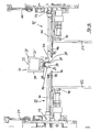
- FIGS. 1 and 2 show in a schematic plan view of an assembly line for sash or door leaf with integrated insulating glass. For the sake of simplicity, only window sashes will be discussed below. For door leaves, however, the corresponding applies.
- wing is intended to include both sliding and pivotable wings.
- the representation in FIG. 2 includes the right end of the illustration FIG. 1 at.
- the production line has a first horizontal conveyor 1 and an obliquely extending second horizontal conveyor 2, which open into a horizontally conveying switch 4, which connects to the third horizontal conveyor 3, which is arranged in alignment with the first horizontal conveyor 1.
- the first horizontal conveyor 1 consists of several sections, starting with a section 5, on which the individual glass panels 52, 53 are successively abandoned, from a section passing through a machine 6 for washing and drying the glass panels, and two sections 7 and 8, which serves for the intermediate transport and, if necessary, also a jamming of the glass panels 52, 53. In addition, in section 7 it is possible to check whether the washed glass panels are actually clean.
- the first horizontal conveyor 1 has a horizontal row of synchronously driven rollers 9, which are located in the sections 5, 7 and 8 at the bottom of a support wall 10 which by a few degrees, z. B. is inclined at 6 ° to the vertical to the rear and is preferably designed as an air cushion wall.
- the glass panels are supported on the rollers 9 standing and leaned against the support wall 10.
- the glass sheets are supported in a conventional manner by an arrangement of washing brushes and rollers.
- the second horizontal conveyor 2 also has a plurality of sections 11, 12, 13, 14 and 15, in each of which an endless conveyor belt 16 is provided with horizontally extending upper strand at the bottom of a support wall 17, which inclined at the same angle from the vertical out backwards The support wall 10.
- the upper strand is arranged at right angles to the support wall 10 and thus also inclined by a few degrees to the rear.
- the second horizontal conveyor 2 is used for conveying rectangular or square frames 51 (see FIG. 1 ), which are formed of plastic hollow sections. They are placed with one of their legs on the conveyor belt 16 and leaned against the support wall 17, in which for the reduction of friction, preferably with bristles, in particular with soft bristles, provided strips are inserted or glued.
- a further row of support rollers 19 is preferably provided in front of this, the height of which can be adjustable and which, if necessary, serve to prevent the frame standing on the conveyor belt 16 from tipping over.
- section 11 of the second horizontal conveyor 2 the frames formed from the hollow plastic profiles 21 are applied to the horizontal conveyor 2.
- the section 12 of the second horizontal conveyor 2 is associated with a system 20, which serves to inject into the space between two webs of the plastic hollow profile, from which the frame 51 is formed for the window sash, an adhesive in which a desiccant is incorporated.
- a system 20 which serves to inject into the space between two webs of the plastic hollow profile, from which the frame 51 is formed for the window sash, an adhesive in which a desiccant is incorporated.
- An example of such a plastic hollow profile is in the FIGS. 16 to 19 shown in cross section.
- the illustrated plastic hollow profile 21 has a flat outer side 22, a structured inner side 23, two flanks 24 and 25 and some hollow chambers. On the inside 23 are two to the flanks 24 and 25 and mutually parallel webs 26 and 27, the gap to the inside of the frame 51 is open.
- the webs 26, 27 are angled at their free end and thereby form a projection 28, to which the glass plates 52, 53 can strike, for which the webs 26 and 27 serve as spacers, see FIG. 18 ,
- an adhesive 29 is injected through the system 20, in which a desiccant is incorporated.
- the adhesive 29 is particularly suitable a polyisobutylene and as a desiccant molecular sieves.
- the adhesive 29 is expediently injected by means of a nozzle 30, which can be moved up and down parallel to the support wall 17 and is rotatable about an axis perpendicular to the support wall 17.
- the nozzle 30 For injecting the adhesive 29 into the space between the vertically extending webs 28, the nozzle 30 is moved upwards or downwards, while the frame 51 formed from the hollow profile 21 rests. In the space between the horizontal webs 26 and 27, the adhesive is 29, while the frame 51 formed from the hollow profile 21 is conveyed horizontally forward or backward and the nozzle 30 rests.
- the section 14 of the second horizontal conveyor 2 is a system 31 for applying a strand 35 of a sealing compound on the opposite sides of the webs 26 and 27 assigned.
- a first nozzle 32 in front of the support wall 17 and a second nozzle 33 behind the support wall 17, from where it can reach through a downwardly extending slot 34 in the support wall 17 through this.
- the nozzles 32 and 33 are movable in the same way as the nozzle 30 and they are synchronously moved and actuated so that they simultaneously apply the sealing compound to the outside of the two webs 26 and 27.
- the strand 35 is shown from the sealant.
- the sections 13 and 15 of the second horizontal conveyor 2 serve for the intermediate transport of the frame. In section 13, if necessary, rungs could be used in the frames 51.
- the in FIG. 1 illustrated section of the production line starts with the switch 4, which between the in FIG. 1 shown two positions back and forth is pivotally.
- the switch 4 has a horizontal conveyor with a structure that is similar to or similar to one of the sections of the second horizontal conveyor 2 and therefore can be regarded as a pivotable continuation of the second horizontal conveyor 2.
- the switch 4 In the position in which the switch 4 is aligned with the first horizontal conveyor 1, it can take over the glass plates 52, 53 conveyed there and transfer them to a preparation station 36.
- the switch 4 In the position in which the switch 4 is aligned with the second horizontal conveyor 2, they can take over this a frame 51 for the window sash.
- the switch 4 In order to be able to transfer the frame 51 into the preparation station 36, however, the switch 4 must first be pivoted into that position in which it aligns with the preparation station 36 and the first horizontal conveyor 1.
- the preparation station 36 is in the FIGS. 3 to 6 shown. It has on a base frame 37, which has two rearwardly inclined rails 38, a frame-shaped Frame 39, which has on its front side two rearwardly inclined posts 40 which project at right angles to the rails 38 upwards.
- the rails 38 extend at a right angle to the conveying direction of the first and third horizontal conveyor 1 and 3.
- the posts 40 are inclined at the same angle to the rear as the support walls 10.
- At the post 40 is an arrangement of three horizontal bars 41, 42nd and 43 slidably mounted up and down, so that the beams 41, 42 and 43 can be adjusted in height.
- the three beams 41, 42, and 43 each carry a horizontal row of free-running support rollers 44 which are rotatable about axes which are parallel to the posts 40.
- a three-lane horizontal conveyor 45 is attached to this, which has a horizontal support 46 for three endless conveyor belts 47, 48 and 49, whose upper run arranged at a distance parallel to each other and inclined at the same angle to the rear as the post 40th
- the two outer conveyor belts 47 and 49 serve to convey glass panels 52, 53, whereas the central conveyor belt 48, which is wider than the outer conveyor belts 47 and 49, is intended to convey a frame 51 for a casement.
- the conveyor belts 47 to 49 are driven separately.
- freewheeling support rollers 50 are arranged on the support. They serve to guide the lower edge of the glass panels and the frame for the window sash. Their axes are parallel to the axes of the rollers 44 attached to the beams 41, 42 and 43.
- each of the three conveyor belts 47, 48 and 49 can be brought into alignment with the horizontal conveyor of the switch 4.
- a frame 51 for a window sash on the middle conveyor belt 48 the support rollers 18 of the switch 4 are aligned with the support rollers 50, which are arranged between the rear conveyor belt 49 and the central conveyor belt 48 and inclined at the same angle to the rear as the posts 40 are.
- this is positioned by transverse displacement of the carrier 46 so that the arranged behind the conveyor belt 49 support rollers 50 are aligned with the support rollers 18 in the switch 4.
- this is positioned by transversely displacing the carrier 46 so that the between the front conveyor belt 47 and the middle conveyor belt 48 arranged support rollers 50 are aligned with the support rollers 18 in the switch 4.
- the frame 51 and the two glass panels 52 and 53 are preferably positioned so that their front upstanding edges are approximately adjacent to one another and adjacent to the subsequent assembly station 54.
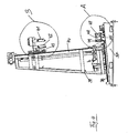
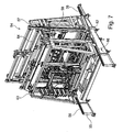
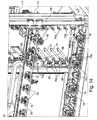
- the assembly station 54 is in the FIGS. 7 to 15 shown. It has a base 55 with rails 56, the inclination of which coincides with the inclination of the rails 38 in the preparation station 36.
- a frame 57 is fixed, which is similar to the frame 39 of the preparation station 36 and how that has an arrangement of three bars 58, 59 and 60.
- a horizontal row of support rollers 61 are mounted, whose axes are approximately perpendicular, namely perpendicular to the rails 56 extend.
- the arrangement of the bars 58 to 60 is like the arrangement of the bars 41 to 43 in the preparation station 36 in height adjustably attached to posts of the frame 57.
- a three-lane horizontal conveyor 62 which is similar in structure to the three-lane horizontal conveyor 45 in the preparation station 36, is height-adjustable on the undercarriage 55.
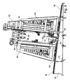
- FIG. 2 shows a view of the rear frame 64.
- Two lateral posts 65 of the rear frame 64 have at their lower ends undercut guide members 66 which engage around the rails 56.
- a horizontal cross member 67 is attached, which by means of toothed belt 68, which are driven by a motor 69, on the post 65 up and down is displaceable.
- On the Traverse 67 stamp 70 are attached, which can be actuated by pressure cylinder 71, in particular by pneumatic cylinder, which in the FIGS.
- each punch 70 is an adjusting device 72nd provided, see FIG. 16 consisting of a pneumatic cylinder 73, whose piston rod 74 has a head 75 to which a parallel to the piston rod 74 guided, extendable strip 76 is attached.
- the adjusting device 72 serves to position the upper leg of the frame 51 and to eliminate any slack in the upper leg of the frame 51, see FIGS. 16 to 18 ,
- a lower cross member 77 of the rear frame 64 also individually actuated plunger 70 and in addition a number of suckers 78 are attached by pressure medium cylinder. Another sucker 78 is attached to the horizontal cross member 68.
- the suckers 78 like the dies 70, can be displaced individually by pressure medium cylinders 89, in particular by pneumatic cylinders.
- a parallel to the post 65 upright cross member 80 is mounted horizontally displaceable.
- the upright cross member 80 crosses the horizontal cross member 67 and is arranged behind this. The displacement of the upright cross member 80 takes place as in the horizontal cross member 67 by means of two toothed belts 81, which are driven by a motor 82.
- FIG. 9 further shows two suckers 85 and 86, which are larger than the suckers 78.
- the lower sucker 85 is in the view of FIG. 9 in the lower left corner of the bounded by the trusses 67, 77, 68 and the post 65 field and is attached to the lower beam 77.
- the upper sucker 86 is located in the diagonally opposite corner of this field. While the lower nipple 85 can only be moved back and forth and the rest of his position the upper cross member 77 retains, the upper nipple 86 may additionally follow the movements of the cross members 67 and 80 so as to maintain its position in the corner of the panel defined by the position of the cross members 67 and 80.
- suckers 85 and 86 With these suckers 85 and 86, a glass sheet 53, which is held by the suckers 78 in the field defined by the trusses 76, 70, 68 and the post 65, can be bent back at two diagonally opposite corners.
- the larger suction cups 85, 86 contribute to the fixation of the glass panels 52, 53, which has to be done before the three-track horizontal conveyor 62 can be lowered.
- the larger suckers 85 and 86 are displaceable by pressure medium cylinders, in particular by pneumatic cylinders 89.
- a two-legged seal 87 is provided, which covers the gap between the frame 51 and the rear glass panel 53 in the lower corner of the frame 51 and thereby seals the access to the gap between the glass panels 52, 53.
- the seal 87 may, for. B. be a molded part of a sponge rubber or the like.
- the guided through the seal 87 end portion of the supply line 88 is preferably a closed at the end, porous pipe piece, which z. B. may consist of a sintered plastic, from which the heavy gas emerges diffusely, flows into the space between the glass plates 52, 53 and the air displaced upwards there, so that the air leaves the gap on the opening caused by the upper sucker 86.
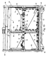
- FIG. 10 shows one of the FIG. 9 corresponding view of the front frame 63, which is arranged in the assembly station in front of the three-lane horizontal conveyor 62 is.
- This front frame 63 is substantially mirror-inverted with the rear frame 64, so that recourse may be had to the description of the rear frame 64 for the details.
- the front frame 63 does not have the larger sucker 85, not the seal 87 and also no supply line 88 for a heavy gas.
- the frame 51 is conveyed to the switch 4. As soon as this has happened, the switch 4 pivots back into alignment with the first horizontal conveyor 1. If this has not been done by then, the frame 39 of the preparation station 36 is next moved transversely on the underframe 37 with the intermediate conveyor belt 48 and the rear conveyor belt 49 arranged row of support rollers 50 in the alignment of the support rollers 18 in the switch 4 brought. Once this is done, the frame 51 is conveyed to the center conveyor belt 48 and conveyed from this to the outlet end of the preparation station 36. If the subsequent assembly station 54 is receptive, the frame 51 can arrive without stopping in the assembly station 54 and simultaneously the two glass panels 52 and 53 conveyed from the preparation station 36 in the assembly station 54.
- the frame 51 is stopped in the preparation station 36.
- the frame 51 and the glass panels 52 and 53 then have the in FIG. 1 taken position shown.
- the frame 51 and the two glass panels 52 and 53 are simultaneously conveyed into the assembly station 54 and moved to the vicinity of the outlet end, where they -. B. xxso be stopped by position sensors that the upright edges of the two glass panels 52, 53 in the conveying direction on the upright edges of the two webs 26 and 27 of the frame 51 are centered. Since the upper runners of the conveyor belts 47, 48 and 49 lie in a common plane, the glass panels 52 and 53 are not yet correctly aligned in height to the height they must occupy in the frame 51, see FIG. 11 ,
- the suckers 78 provided in the two racks 63 and 64 of the assembly station 54 are advanced and activated as far as the adjacent glass panel 52 or 53 by actuation of pneumatic cylinders 89, to the piston rod of which a respective suction device 78 is attached. so that the two glass sheets are sucked in and fixed in their position.
- only those suckers 78 are advanced and activated, which are required for the length and height of the respective glass panels 52 and 53.
- the dimensions of the glass panels 52, 53 may be known from manufacturing planning and may be dictated to the control of the assembly station 54, or may be determined by position sensors provided in the assembly apparatus 54.
- the trusses 67 and 80 can be adjusted in this way automatically to the current dimension of the glass panels 52, 53 and the associated frame 51.
- the adjustment of the trusses 67 and 80 to the dimensions of the current frame 51 includes the alignment of the punches 70, 70a, for which purpose the slides 83 are displaced to a position in which the punches 70, 70a reach the edge of the glass panels 52, 53 opposite possible uniform distances.
- suckers 78 which in the sense of FIG. 9 in the lower left, by the trusses 67, 77 and 80 and by the post 65 limited field are activated.
- the larger suckers 85 and 86 are advanced and activated against the glass sheets 52 and 53.
- the three-lane balance conveyor 62 can be lowered in the assembly station 54. As a result, the upper leg of the frame 51 on the strips 76th deposed, see FIG. 17 , And any slack of the upper leg of the frame 51 is eliminated.
- the three-lane horizontal conveyor 62 is lowered until the horizontal edges of the glass panels 52 and 53 are centered on the horizontal edges of the webs 26 and 27.
- the strands 35 of the sealant now lie opposite the glass sheets 52, 53 near their edge.
- the beams 58, 59 and 60 are raised so that the support rollers 61 disengage from the glass panels 52, 53.
- the front frame 63 and the rear frame 64 are both moved towards each other, thereby pressing the glass sheets 52 and 53 against the string 35 of sealant which is on the lands 26 and 27.
- the movement of the frames 63 and 64 is thereby cushioned by the pneumatic cylinder 71 of the punches 70, 70a, which provide for a pressing of the glass sheets 52, 53 to the webs 26 and 27 of the frame 51 with a predetermined pressure, see FIG. 18 ,
- the insulating glass pane integrated into the window sash is to be filled with a heavy gas, this is done by bending the rear glass plate 53 outwards against the frame 51 by pressing the glass plate 53 against diagonally opposite corners - see FIG. 19 -, Wherein, by the access, which was produced by the suction 85, the heavy gas introduced and from the opening, which was produced by the sucker 86, air is displaced from the space between the two glass sheets 52 and 53. If a sufficiently high degree of filling of the heavy gas is achieved, the suckers 85 and 86 are deactivated, whereby the openings due to the elastic resilience Close the glass panels 52 and 53 readily and be closed by the action of the pneumatically operated punch 70, 70 a.
- FIG. 19 shows in detail the access 91 at a lower corner of the sash with the attached seal 87 and a portion of the porous feed line 88 through which the heavy gas is supplied, and between the seal 87 and the glass sheet 53 a portion of the elastomeric suction cup of the suction 85th
Landscapes
- Engineering & Computer Science (AREA)
- Civil Engineering (AREA)
- Structural Engineering (AREA)
- Securing Of Glass Panes Or The Like (AREA)
- Sheets, Magazines, And Separation Thereof (AREA)
Priority Applications (1)
| Application Number | Priority Date | Filing Date | Title |
|---|---|---|---|
| PL10754874T PL2483504T3 (pl) | 2009-09-30 | 2010-09-11 | Urządzenie do montażu skrzydła okiennego ze zintegrowaną szybą zespoloną |
Applications Claiming Priority (2)
| Application Number | Priority Date | Filing Date | Title |
|---|---|---|---|
| DE102009048642A DE102009048642B4 (de) | 2009-09-30 | 2009-09-30 | Vorrichtung zum Zusammenbauen eines Fensterflügels mit integrierter Isolierglasscheibe |
| PCT/EP2010/005578 WO2011038832A1 (de) | 2009-09-30 | 2010-09-11 | Vorrichtung zum zusammenbauen eines fensterflügels mit integrierter isolierglasscheibe |
Publications (2)
| Publication Number | Publication Date |
|---|---|
| EP2483504A1 EP2483504A1 (de) | 2012-08-08 |
| EP2483504B1 true EP2483504B1 (de) | 2014-03-26 |
Family
ID=43335662
Family Applications (1)
| Application Number | Title | Priority Date | Filing Date |
|---|---|---|---|
| EP10754874.5A Active EP2483504B1 (de) | 2009-09-30 | 2010-09-11 | Vorrichtung zum zusammenbauen eines fensterflügels mit integrierter isolierglasscheibe |
Country Status (6)
| Country | Link |
|---|---|
| US (1) | US9021687B2 (pl) |
| EP (1) | EP2483504B1 (pl) |
| DE (1) | DE102009048642B4 (pl) |
| PL (1) | PL2483504T3 (pl) |
| RU (1) | RU2534050C2 (pl) |
| WO (1) | WO2011038832A1 (pl) |
Families Citing this family (11)
| Publication number | Priority date | Publication date | Assignee | Title |
|---|---|---|---|---|
| US9309714B2 (en) | 2007-11-13 | 2016-04-12 | Guardian Ig, Llc | Rotating spacer applicator for window assembly |
| EP2580418B1 (en) | 2010-06-10 | 2014-08-13 | Guardian IG, LLC | Window spacer applicator |
| EP2808477A1 (de) * | 2012-01-13 | 2014-12-03 | Plus Inventia AG | Vorrichtung zum Zusammenbau von Isolierglasscheiben |
| US9689196B2 (en) * | 2012-10-22 | 2017-06-27 | Guardian Ig, Llc | Assembly equipment line and method for windows |
| US9656356B2 (en) * | 2013-01-22 | 2017-05-23 | Guardian Ig, Llc | Window unit assembly station and method |
| US10113354B2 (en) | 2013-12-31 | 2018-10-30 | Cardinal Ig Company | Multiple-pane insulating glazing unit assembly, gas filling, and pressing machine |
| WO2016101029A1 (en) * | 2014-12-23 | 2016-06-30 | Howard Bruce | Sash press |
| WO2017155480A1 (en) * | 2016-03-09 | 2017-09-14 | Cms Maki̇na San. Ve Ti̇c. A. Ş. | Automated exterior glass and window glass cassette / frame joining and bonding line |
| CN111099818B (zh) * | 2020-01-06 | 2022-04-08 | 新宁县中恺钢化玻璃有限公司 | 一种中空玻璃、加工机械及加工方法 |
| CN117533720A (zh) * | 2023-12-13 | 2024-02-09 | 济南天辰智能装备股份有限公司 | 一种门窗生产线及生产方法 |
| WO2025207044A1 (en) * | 2024-03-27 | 2025-10-02 | Cms Maki̇ne Sanayi̇ Ve Ti̇caret Anoni̇m Şi̇rketi̇ | Automated exterior glass and window glass cassette / frame joining and bonding line |
Family Cites Families (9)
| Publication number | Priority date | Publication date | Assignee | Title |
|---|---|---|---|---|
| US6286288B1 (en) | 1996-12-05 | 2001-09-11 | Vertical Ventures V-5, Llc | Integrated multipane window unit and sash assembly and method for manufacturing the same |
| US6055783A (en) | 1997-09-15 | 2000-05-02 | Andersen Corporation | Unitary insulated glass unit and method of manufacture |
| DE10138346C2 (de) * | 2001-08-03 | 2003-12-04 | Lenhardt Maschinenbau | Vorrichtung zum Zusammenbauen von Isolierglasscheiben |
| US20040074588A1 (en) | 2002-10-21 | 2004-04-22 | Sashlite, Llc | Assembly of insulating glass structures on an integrated sash |
| DE102004009858B4 (de) * | 2004-02-25 | 2006-05-04 | Karl Lenhardt | Verfahren zum Positionieren von Glastafeln in einer vertikalen Zusammenbau- und Pressvorrichtung für Isolierglasscheiben |
| GB0419393D0 (en) * | 2004-09-01 | 2004-10-06 | Diageo Plc | Adjustable conveyor guide |
| RU82257U1 (ru) * | 2008-12-04 | 2009-04-20 | Общество с ограниченной ответственностью Региональная производственная компания | Комплект профилей для сборки оконных блоков |
| RU82258U1 (ru) * | 2008-12-29 | 2009-04-20 | Закрытое акционерное общество "Прок" | Профильная створка из поливинилхлорида для изготовления оконных и дверных конструкций |
| US8381382B2 (en) * | 2009-12-31 | 2013-02-26 | Cardinal Ig Company | Methods and equipment for assembling triple-pane insulating glass units |
-
2009
- 2009-09-30 DE DE102009048642A patent/DE102009048642B4/de not_active Expired - Fee Related
-
2010
- 2010-09-11 WO PCT/EP2010/005578 patent/WO2011038832A1/de not_active Ceased
- 2010-09-11 US US13/499,028 patent/US9021687B2/en active Active
- 2010-09-11 EP EP10754874.5A patent/EP2483504B1/de active Active
- 2010-09-11 RU RU2012116620/12A patent/RU2534050C2/ru not_active IP Right Cessation
- 2010-09-11 PL PL10754874T patent/PL2483504T3/pl unknown
Also Published As
| Publication number | Publication date |
|---|---|
| US9021687B2 (en) | 2015-05-05 |
| EP2483504A1 (de) | 2012-08-08 |
| WO2011038832A1 (de) | 2011-04-07 |
| DE102009048642B4 (de) | 2013-07-04 |
| US20120266455A1 (en) | 2012-10-25 |
| RU2534050C2 (ru) | 2014-11-27 |
| PL2483504T3 (pl) | 2014-10-31 |
| RU2012116620A (ru) | 2013-11-10 |
| DE102009048642A1 (de) | 2011-03-31 |
Similar Documents
| Publication | Publication Date | Title |
|---|---|---|
| DE102009048642B4 (de) | Vorrichtung zum Zusammenbauen eines Fensterflügels mit integrierter Isolierglasscheibe | |
| EP0213513B1 (de) | Vorrichtung zum Verbinden zweier Glastafeln zu einer randverklebten Isolierglasscheibe | |
| EP0222349B1 (de) | Vorrichtung für das schlupffreie Fördern von zwei Tafeln, insbesondere von Glastafeln | |
| EP2483503B1 (de) | Verfahren zum zusammenbauen eines fensterflügels mit integrierter isolierglasscheibe | |
| DE29504900U1 (de) | Vorrichtung zum Zusammenbauen von Isolierglasscheiben, deren Innenraum mit einem Schwergas gefüllt ist | |
| DE9100308U1 (de) | Anlage zur Herstellung von Isolierglasscheiben | |
| EP1157184B2 (de) | Vorrichtung zum fördern von isolierglasscheiben | |
| EP1730378B1 (de) | Verfahren zum positionieren von glastafeln in einer vertikalen zusammenbau- und pressvorrichtung für isolierglasscheiben | |
| EP3133234B1 (de) | Verfahren und vorrichtung zum zusammenbauen von glastafeln zu isolierglasscheiben | |
| EP1725733B1 (de) | Verfahren und vorrichtung zum zusammenbauen von isolierglasscheiben, die mit einem von luft verschiedenen gas gefüllt sind | |
| EP1769130A1 (de) | Verfahren und vorrichtung zum zusammenbauen von isolierglasscheiben, die mit einem von luft verschiedenen gas gefüllt sind | |
| DE4231424C2 (de) | Verfahren und Vorrichtung zum Zusammenbauen von Isolierglasscheiben, deren Glastafeln durch einen plastischen Abstandhalter auf Abstand gehalten und miteinander verklebt sind | |
| EP0857849B1 (de) | Verfahren und Vorrichtung zum Zusammenbauen und Versiegeln von Isolierglasscheiben | |
| EP0857848B1 (de) | Verfahren und Vorrichtung zum Zusammenbauen von Isolierglasscheiben | |
| DE202010007183U1 (de) | Vorrichtung zum Zusammenbauen eines Fensterflügels mit integrierter Isolierglasscheibe | |
| WO1995011363A1 (de) | Verfahren und vorrichtung zum zusammenbauen von isolierglasscheiben mit rahmenförmigen abstandhaltern aus einer plastischen masse | |
| DE102006018333A1 (de) | Vorrichtung zum Zusammenbauen von Insolierglasscheiben, die mit einem von Luft verschiedenen Gas gefüllt sind | |
| DE19505771C1 (de) | Anlage zum Herstellen von Isolierglasscheiben mit Abstandhalter auf Kunststoffbasis | |
| EP4682094A1 (de) | Einrichtung und verfahren zum unabhängigen transportieren von zwei glasscheiben in einer scheibenbearbeitungsvorrichtung | |
| DE4404029A1 (de) | Verfahren und Vorrichtung zum Zusammenbauen von Isolierglasscheiben mit rahmenförmigen Abstandhaltern aus einer plastischen Masse | |
| EP1111182A2 (de) | Einrichtung zum Abdichten einer Randfuge einer noch nicht geschlossenen Isolierglasscheibe an einer Vorrichtung zum Zusammenbauen von Isolierglasscheiben | |
| DE29922490U1 (de) | Einrichtung zum Abdichten einer Randfuge einer noch nicht geschlossenen Isolierglasscheibe an einer Vorrichtung zum Zusammenbauen von Isolierglasscheiben | |
| DE9205069U1 (de) | Vorrichtung zum Zusammenbauen von zwei Isolierglasscheiben die mit einem von Luft verschiedenen Gas gefüllt sind |
Legal Events
| Date | Code | Title | Description |
|---|---|---|---|
| PUAI | Public reference made under article 153(3) epc to a published international application that has entered the european phase |
Free format text: ORIGINAL CODE: 0009012 |
|
| 17P | Request for examination filed |
Effective date: 20120425 |
|
| AK | Designated contracting states |
Kind code of ref document: A1 Designated state(s): AL AT BE BG CH CY CZ DE DK EE ES FI FR GB GR HR HU IE IS IT LI LT LU LV MC MK MT NL NO PL PT RO SE SI SK SM TR |
|
| DAX | Request for extension of the european patent (deleted) | ||
| GRAP | Despatch of communication of intention to grant a patent |
Free format text: ORIGINAL CODE: EPIDOSNIGR1 |
|
| INTG | Intention to grant announced |
Effective date: 20131017 |
|
| GRAS | Grant fee paid |
Free format text: ORIGINAL CODE: EPIDOSNIGR3 |
|
| GRAA | (expected) grant |
Free format text: ORIGINAL CODE: 0009210 |
|
| AK | Designated contracting states |
Kind code of ref document: B1 Designated state(s): AL AT BE BG CH CY CZ DE DK EE ES FI FR GB GR HR HU IE IS IT LI LT LU LV MC MK MT NL NO PL PT RO SE SI SK SM TR |
|
| REG | Reference to a national code |
Ref country code: GB Ref legal event code: FG4D Free format text: NOT ENGLISH |
|
| REG | Reference to a national code |
Ref country code: CH Ref legal event code: EP |
|
| REG | Reference to a national code |
Ref country code: AT Ref legal event code: REF Ref document number: 659117 Country of ref document: AT Kind code of ref document: T Effective date: 20140415 |
|
| REG | Reference to a national code |
Ref country code: IE Ref legal event code: FG4D Free format text: LANGUAGE OF EP DOCUMENT: GERMAN |
|
| REG | Reference to a national code |
Ref country code: DE Ref legal event code: R096 Ref document number: 502010006493 Country of ref document: DE Effective date: 20140508 |
|
| REG | Reference to a national code |
Ref country code: CH Ref legal event code: NV Representative=s name: BOVARD AG, CH |
|
| PG25 | Lapsed in a contracting state [announced via postgrant information from national office to epo] |
Ref country code: NO Free format text: LAPSE BECAUSE OF FAILURE TO SUBMIT A TRANSLATION OF THE DESCRIPTION OR TO PAY THE FEE WITHIN THE PRESCRIBED TIME-LIMIT Effective date: 20140626 Ref country code: LT Free format text: LAPSE BECAUSE OF FAILURE TO SUBMIT A TRANSLATION OF THE DESCRIPTION OR TO PAY THE FEE WITHIN THE PRESCRIBED TIME-LIMIT Effective date: 20140326 |
|
| REG | Reference to a national code |
Ref country code: NL Ref legal event code: VDEP Effective date: 20140326 |
|
| REG | Reference to a national code |
Ref country code: LT Ref legal event code: MG4D |
|
| PG25 | Lapsed in a contracting state [announced via postgrant information from national office to epo] |
Ref country code: FI Free format text: LAPSE BECAUSE OF FAILURE TO SUBMIT A TRANSLATION OF THE DESCRIPTION OR TO PAY THE FEE WITHIN THE PRESCRIBED TIME-LIMIT Effective date: 20140326 Ref country code: SE Free format text: LAPSE BECAUSE OF FAILURE TO SUBMIT A TRANSLATION OF THE DESCRIPTION OR TO PAY THE FEE WITHIN THE PRESCRIBED TIME-LIMIT Effective date: 20140326 |
|
| PG25 | Lapsed in a contracting state [announced via postgrant information from national office to epo] |
Ref country code: HR Free format text: LAPSE BECAUSE OF FAILURE TO SUBMIT A TRANSLATION OF THE DESCRIPTION OR TO PAY THE FEE WITHIN THE PRESCRIBED TIME-LIMIT Effective date: 20140326 Ref country code: LV Free format text: LAPSE BECAUSE OF FAILURE TO SUBMIT A TRANSLATION OF THE DESCRIPTION OR TO PAY THE FEE WITHIN THE PRESCRIBED TIME-LIMIT Effective date: 20140326 |
|
| PG25 | Lapsed in a contracting state [announced via postgrant information from national office to epo] |
Ref country code: CY Free format text: LAPSE BECAUSE OF FAILURE TO SUBMIT A TRANSLATION OF THE DESCRIPTION OR TO PAY THE FEE WITHIN THE PRESCRIBED TIME-LIMIT Effective date: 20140326 Ref country code: CZ Free format text: LAPSE BECAUSE OF FAILURE TO SUBMIT A TRANSLATION OF THE DESCRIPTION OR TO PAY THE FEE WITHIN THE PRESCRIBED TIME-LIMIT Effective date: 20140326 Ref country code: EE Free format text: LAPSE BECAUSE OF FAILURE TO SUBMIT A TRANSLATION OF THE DESCRIPTION OR TO PAY THE FEE WITHIN THE PRESCRIBED TIME-LIMIT Effective date: 20140326 Ref country code: NL Free format text: LAPSE BECAUSE OF FAILURE TO SUBMIT A TRANSLATION OF THE DESCRIPTION OR TO PAY THE FEE WITHIN THE PRESCRIBED TIME-LIMIT Effective date: 20140326 Ref country code: IS Free format text: LAPSE BECAUSE OF FAILURE TO SUBMIT A TRANSLATION OF THE DESCRIPTION OR TO PAY THE FEE WITHIN THE PRESCRIBED TIME-LIMIT Effective date: 20140726 Ref country code: RO Free format text: LAPSE BECAUSE OF FAILURE TO SUBMIT A TRANSLATION OF THE DESCRIPTION OR TO PAY THE FEE WITHIN THE PRESCRIBED TIME-LIMIT Effective date: 20140326 Ref country code: BG Free format text: LAPSE BECAUSE OF FAILURE TO SUBMIT A TRANSLATION OF THE DESCRIPTION OR TO PAY THE FEE WITHIN THE PRESCRIBED TIME-LIMIT Effective date: 20140626 |
|
| REG | Reference to a national code |
Ref country code: PL Ref legal event code: T3 |
|
| PG25 | Lapsed in a contracting state [announced via postgrant information from national office to epo] |
Ref country code: SK Free format text: LAPSE BECAUSE OF FAILURE TO SUBMIT A TRANSLATION OF THE DESCRIPTION OR TO PAY THE FEE WITHIN THE PRESCRIBED TIME-LIMIT Effective date: 20140326 Ref country code: ES Free format text: LAPSE BECAUSE OF FAILURE TO SUBMIT A TRANSLATION OF THE DESCRIPTION OR TO PAY THE FEE WITHIN THE PRESCRIBED TIME-LIMIT Effective date: 20140326 |
|
| PG25 | Lapsed in a contracting state [announced via postgrant information from national office to epo] |
Ref country code: PT Free format text: LAPSE BECAUSE OF FAILURE TO SUBMIT A TRANSLATION OF THE DESCRIPTION OR TO PAY THE FEE WITHIN THE PRESCRIBED TIME-LIMIT Effective date: 20140728 |
|
| REG | Reference to a national code |
Ref country code: DE Ref legal event code: R097 Ref document number: 502010006493 Country of ref document: DE |
|
| PG25 | Lapsed in a contracting state [announced via postgrant information from national office to epo] |
Ref country code: DK Free format text: LAPSE BECAUSE OF FAILURE TO SUBMIT A TRANSLATION OF THE DESCRIPTION OR TO PAY THE FEE WITHIN THE PRESCRIBED TIME-LIMIT Effective date: 20140326 |
|
| PLBE | No opposition filed within time limit |
Free format text: ORIGINAL CODE: 0009261 |
|
| STAA | Information on the status of an ep patent application or granted ep patent |
Free format text: STATUS: NO OPPOSITION FILED WITHIN TIME LIMIT |
|
| 26N | No opposition filed |
Effective date: 20150106 |
|
| REG | Reference to a national code |
Ref country code: DE Ref legal event code: R097 Ref document number: 502010006493 Country of ref document: DE Effective date: 20150106 |
|
| PG25 | Lapsed in a contracting state [announced via postgrant information from national office to epo] |
Ref country code: MC Free format text: LAPSE BECAUSE OF FAILURE TO SUBMIT A TRANSLATION OF THE DESCRIPTION OR TO PAY THE FEE WITHIN THE PRESCRIBED TIME-LIMIT Effective date: 20140326 Ref country code: LU Free format text: LAPSE BECAUSE OF FAILURE TO SUBMIT A TRANSLATION OF THE DESCRIPTION OR TO PAY THE FEE WITHIN THE PRESCRIBED TIME-LIMIT Effective date: 20140911 |
|
| GBPC | Gb: european patent ceased through non-payment of renewal fee |
Effective date: 20140911 |
|
| REG | Reference to a national code |
Ref country code: IE Ref legal event code: MM4A |
|
| PG25 | Lapsed in a contracting state [announced via postgrant information from national office to epo] |
Ref country code: BE Free format text: LAPSE BECAUSE OF NON-PAYMENT OF DUE FEES Effective date: 20140930 |
|
| PG25 | Lapsed in a contracting state [announced via postgrant information from national office to epo] |
Ref country code: SI Free format text: LAPSE BECAUSE OF FAILURE TO SUBMIT A TRANSLATION OF THE DESCRIPTION OR TO PAY THE FEE WITHIN THE PRESCRIBED TIME-LIMIT Effective date: 20140326 Ref country code: GB Free format text: LAPSE BECAUSE OF NON-PAYMENT OF DUE FEES Effective date: 20140911 |
|
| PG25 | Lapsed in a contracting state [announced via postgrant information from national office to epo] |
Ref country code: IE Free format text: LAPSE BECAUSE OF NON-PAYMENT OF DUE FEES Effective date: 20140911 |
|
| PG25 | Lapsed in a contracting state [announced via postgrant information from national office to epo] |
Ref country code: SM Free format text: LAPSE BECAUSE OF FAILURE TO SUBMIT A TRANSLATION OF THE DESCRIPTION OR TO PAY THE FEE WITHIN THE PRESCRIBED TIME-LIMIT Effective date: 20140326 |
|
| PG25 | Lapsed in a contracting state [announced via postgrant information from national office to epo] |
Ref country code: GR Free format text: LAPSE BECAUSE OF FAILURE TO SUBMIT A TRANSLATION OF THE DESCRIPTION OR TO PAY THE FEE WITHIN THE PRESCRIBED TIME-LIMIT Effective date: 20140627 Ref country code: MT Free format text: LAPSE BECAUSE OF FAILURE TO SUBMIT A TRANSLATION OF THE DESCRIPTION OR TO PAY THE FEE WITHIN THE PRESCRIBED TIME-LIMIT Effective date: 20140326 |
|
| PG25 | Lapsed in a contracting state [announced via postgrant information from national office to epo] |
Ref country code: TR Free format text: LAPSE BECAUSE OF FAILURE TO SUBMIT A TRANSLATION OF THE DESCRIPTION OR TO PAY THE FEE WITHIN THE PRESCRIBED TIME-LIMIT Effective date: 20140326 Ref country code: HU Free format text: LAPSE BECAUSE OF FAILURE TO SUBMIT A TRANSLATION OF THE DESCRIPTION OR TO PAY THE FEE WITHIN THE PRESCRIBED TIME-LIMIT; INVALID AB INITIO Effective date: 20100911 |
|
| REG | Reference to a national code |
Ref country code: FR Ref legal event code: PLFP Year of fee payment: 7 |
|
| REG | Reference to a national code |
Ref country code: FR Ref legal event code: PLFP Year of fee payment: 8 |
|
| PG25 | Lapsed in a contracting state [announced via postgrant information from national office to epo] |
Ref country code: MK Free format text: LAPSE BECAUSE OF FAILURE TO SUBMIT A TRANSLATION OF THE DESCRIPTION OR TO PAY THE FEE WITHIN THE PRESCRIBED TIME-LIMIT Effective date: 20140326 |
|
| REG | Reference to a national code |
Ref country code: FR Ref legal event code: PLFP Year of fee payment: 9 |
|
| PG25 | Lapsed in a contracting state [announced via postgrant information from national office to epo] |
Ref country code: AL Free format text: LAPSE BECAUSE OF FAILURE TO SUBMIT A TRANSLATION OF THE DESCRIPTION OR TO PAY THE FEE WITHIN THE PRESCRIBED TIME-LIMIT Effective date: 20140326 |
|
| PGFP | Annual fee paid to national office [announced via postgrant information from national office to epo] |
Ref country code: SE Payment date: 20180827 Year of fee payment: 9 |
|
| PGFP | Annual fee paid to national office [announced via postgrant information from national office to epo] |
Ref country code: FR Payment date: 20190924 Year of fee payment: 10 |
|
| PGFP | Annual fee paid to national office [announced via postgrant information from national office to epo] |
Ref country code: PL Payment date: 20190723 Year of fee payment: 10 |
|
| REG | Reference to a national code |
Ref country code: CH Ref legal event code: PL |
|
| PG25 | Lapsed in a contracting state [announced via postgrant information from national office to epo] |
Ref country code: LI Free format text: LAPSE BECAUSE OF NON-PAYMENT OF DUE FEES Effective date: 20190930 Ref country code: CH Free format text: LAPSE BECAUSE OF NON-PAYMENT OF DUE FEES Effective date: 20190930 |
|
| PG25 | Lapsed in a contracting state [announced via postgrant information from national office to epo] |
Ref country code: FR Free format text: LAPSE BECAUSE OF NON-PAYMENT OF DUE FEES Effective date: 20200930 |
|
| PG25 | Lapsed in a contracting state [announced via postgrant information from national office to epo] |
Ref country code: PL Free format text: LAPSE BECAUSE OF NON-PAYMENT OF DUE FEES Effective date: 20200911 |
|
| PGFP | Annual fee paid to national office [announced via postgrant information from national office to epo] |
Ref country code: DE Payment date: 20250929 Year of fee payment: 16 |
|
| PGFP | Annual fee paid to national office [announced via postgrant information from national office to epo] |
Ref country code: IT Payment date: 20250919 Year of fee payment: 16 |
|
| PGFP | Annual fee paid to national office [announced via postgrant information from national office to epo] |
Ref country code: AT Payment date: 20250929 Year of fee payment: 16 |