EP2483459B1 - Surface preparation unit for metal strips processing lines - Google Patents
Surface preparation unit for metal strips processing lines Download PDFInfo
- Publication number
- EP2483459B1 EP2483459B1 EP10776141.3A EP10776141A EP2483459B1 EP 2483459 B1 EP2483459 B1 EP 2483459B1 EP 10776141 A EP10776141 A EP 10776141A EP 2483459 B1 EP2483459 B1 EP 2483459B1
- Authority
- EP
- European Patent Office
- Prior art keywords
- strip
- tank
- unit according
- electrodes
- submersion
- Prior art date
- Legal status (The legal status is an assumption and is not a legal conclusion. Google has not performed a legal analysis and makes no representation as to the accuracy of the status listed.)
- Active
Links
Images
Classifications
-
- C—CHEMISTRY; METALLURGY
- C25—ELECTROLYTIC OR ELECTROPHORETIC PROCESSES; APPARATUS THEREFOR
- C25F—PROCESSES FOR THE ELECTROLYTIC REMOVAL OF MATERIALS FROM OBJECTS; APPARATUS THEREFOR
- C25F1/00—Electrolytic cleaning, degreasing, pickling or descaling
- C25F1/02—Pickling; Descaling
-
- C—CHEMISTRY; METALLURGY
- C25—ELECTROLYTIC OR ELECTROPHORETIC PROCESSES; APPARATUS THEREFOR
- C25D—PROCESSES FOR THE ELECTROLYTIC OR ELECTROPHORETIC PRODUCTION OF COATINGS; ELECTROFORMING; APPARATUS THEREFOR
- C25D17/00—Constructional parts, or assemblies thereof, of cells for electrolytic coating
- C25D17/02—Tanks; Installations therefor
-
- C—CHEMISTRY; METALLURGY
- C25—ELECTROLYTIC OR ELECTROPHORETIC PROCESSES; APPARATUS THEREFOR
- C25D—PROCESSES FOR THE ELECTROLYTIC OR ELECTROPHORETIC PRODUCTION OF COATINGS; ELECTROFORMING; APPARATUS THEREFOR
- C25D17/00—Constructional parts, or assemblies thereof, of cells for electrolytic coating
- C25D17/10—Electrodes, e.g. composition, counter electrode
- C25D17/12—Shape or form
-
- C—CHEMISTRY; METALLURGY
- C25—ELECTROLYTIC OR ELECTROPHORETIC PROCESSES; APPARATUS THEREFOR
- C25D—PROCESSES FOR THE ELECTROLYTIC OR ELECTROPHORETIC PRODUCTION OF COATINGS; ELECTROFORMING; APPARATUS THEREFOR
- C25D21/00—Processes for servicing or operating cells for electrolytic coating
- C25D21/04—Removal of gases or vapours ; Gas or pressure control
-
- C—CHEMISTRY; METALLURGY
- C25—ELECTROLYTIC OR ELECTROPHORETIC PROCESSES; APPARATUS THEREFOR
- C25D—PROCESSES FOR THE ELECTROLYTIC OR ELECTROPHORETIC PRODUCTION OF COATINGS; ELECTROFORMING; APPARATUS THEREFOR
- C25D21/00—Processes for servicing or operating cells for electrolytic coating
- C25D21/10—Agitating of electrolytes; Moving of racks
-
- C—CHEMISTRY; METALLURGY
- C25—ELECTROLYTIC OR ELECTROPHORETIC PROCESSES; APPARATUS THEREFOR
- C25D—PROCESSES FOR THE ELECTROLYTIC OR ELECTROPHORETIC PRODUCTION OF COATINGS; ELECTROFORMING; APPARATUS THEREFOR
- C25D21/00—Processes for servicing or operating cells for electrolytic coating
- C25D21/12—Process control or regulation
-
- C—CHEMISTRY; METALLURGY
- C25—ELECTROLYTIC OR ELECTROPHORETIC PROCESSES; APPARATUS THEREFOR
- C25D—PROCESSES FOR THE ELECTROLYTIC OR ELECTROPHORETIC PRODUCTION OF COATINGS; ELECTROFORMING; APPARATUS THEREFOR
- C25D21/00—Processes for servicing or operating cells for electrolytic coating
- C25D21/16—Regeneration of process solutions
- C25D21/18—Regeneration of process solutions of electrolytes
-
- C—CHEMISTRY; METALLURGY
- C25—ELECTROLYTIC OR ELECTROPHORETIC PROCESSES; APPARATUS THEREFOR
- C25D—PROCESSES FOR THE ELECTROLYTIC OR ELECTROPHORETIC PRODUCTION OF COATINGS; ELECTROFORMING; APPARATUS THEREFOR
- C25D5/00—Electroplating characterised by the process; Pretreatment or after-treatment of workpieces
- C25D5/08—Electroplating with moving electrolyte e.g. jet electroplating
-
- C—CHEMISTRY; METALLURGY
- C25—ELECTROLYTIC OR ELECTROPHORETIC PROCESSES; APPARATUS THEREFOR
- C25D—PROCESSES FOR THE ELECTROLYTIC OR ELECTROPHORETIC PRODUCTION OF COATINGS; ELECTROFORMING; APPARATUS THEREFOR
- C25D5/00—Electroplating characterised by the process; Pretreatment or after-treatment of workpieces
- C25D5/18—Electroplating using modulated, pulsed or reversing current
-
- C—CHEMISTRY; METALLURGY
- C25—ELECTROLYTIC OR ELECTROPHORETIC PROCESSES; APPARATUS THEREFOR
- C25D—PROCESSES FOR THE ELECTROLYTIC OR ELECTROPHORETIC PRODUCTION OF COATINGS; ELECTROFORMING; APPARATUS THEREFOR
- C25D7/00—Electroplating characterised by the article coated
- C25D7/06—Wires; Strips; Foils
- C25D7/0614—Strips or foils
- C25D7/0621—In horizontal cells
-
- C—CHEMISTRY; METALLURGY
- C25—ELECTROLYTIC OR ELECTROPHORETIC PROCESSES; APPARATUS THEREFOR
- C25F—PROCESSES FOR THE ELECTROLYTIC REMOVAL OF MATERIALS FROM OBJECTS; APPARATUS THEREFOR
- C25F7/00—Constructional parts, or assemblies thereof, of cells for electrolytic removal of material from objects; Servicing or operating
Definitions
- the present invention refers to a surface preparation unit for metal strips processing lines.
- surface preparation for metal strips is used for indicating the descaling and/or pickling operations.
- the conventionally most commonly used configuration is that referred to as direct current (DC) "grid to grid".
- DC direct current
- the strip generally kept at a neutral potential, often “earthed", is submerged in a conductive solution (acid or neutral) and it passes through electrodes also submerged in the electrolyte.
- the electrodes, or electrode cells, formed by extended and continuous armatures facing the two larger surfaces of the strip, are generally kept at the same potential (positive - anodic or negative - cathodic).
- the strip in these conditions, locally behaves like an armature having a sign opposite to that of the grids towards which it faces progressively.
- New processes such as those, for example, described in patent application WO 02/50344 A1 and WO 02/086199 A2 , based on the use of alternating currents, provide a valid solution to most of the abovementioned drawbacks.
- introduction thereof into conventional tanks may lead to results relatively lower than expected and this due to the fact that greater efficiency thereof only worsens the practical problems, such as for example the removal of the sludge or the evacuation of the gases produced in the electrolysis which may have a drastic impact on the operation of the tank, regardless of the process used therein.
- An object of the present invention is that of providing a surface preparation unit for metal strips processing lines for accommodating direct current, alternating current or combined alternating/direct current high efficiency electrolytic descaling and/or pickling processes.
- Another object of the present invention is that of providing a surface preparation unit for metal strips processing lines capable of disposing the high production of sludge and gas typical of the high efficiency electrolytic descaling and/or pickling processes.
- Another object of the present invention is that of providing a surface preparation unit for metal strips processing lines which is particularly simple and functional, with low costs.
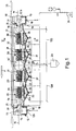
- a surface preparation unit for metal strips processing lines generally indicated with 10 is shown.
- the unit comprises a tank 12, through which a strip 11 to be treated is continuously fed in the direction of the arrow F and returned on a system for the suspension/submersion of the strip made up of a plurality of rollers.
- the tank 12 comprises a main treatment portion 12a, containing an electrolyte solution, and two opposite end portions 12b respectively bearing an input roller 13 and an output deflection roller 14, which may be coupled to a wringing roller 15.
- the end portions 12b of the tank 12 are delimited by a wall 16 for holding the electrolyte, the wall rising from a bottom wall of the tank 12.
- the end portions 12b do not contain electrolyte but they contain a valve 18 at the bottom.
- Submersion rollers 19, which divert the strip 11 beneath the free fluid surface of the electrolyte contained in the tank 12 are respectively arranged immediately downstream of the input roller 13 and immediately upstream of the output roller 14, at each end of the main treatment portion 12a.
- a partition roller 19' arranged at the centre of the tank 12, divides the path of the strip 11 into two free spans 100, each comprised between the submersion roller 19 and the partition roller 19'.
- Each free span 100 contains at least one electrode cell 20, made up of upper and lower electrodes 21 with respect to the strip 11, comprising upper and lower armatures 22, facing the two larger surfaces of the strip 11.
- Figure 1 shows two electrode cells 20 for each free span 100 spaced from each other in the longitudinal direction.
- upper or lower electrode 21 is used to indicate the complete structure that bears a given polarity facing the strip, localized in the armature 22 of the electrode 21, including the mechanical support structure as well as the electric connection one.
- the free span 100 between two successive submersion rollers 19 be preferably comprised between 3.5 m and 7 m.
- a tank 12 shall be provided with only two submersion rollers 19 should the distance between centres thereof, i.e. the free span 100 therebetween be limited between 3.5 and 7 m. Should it be larger, the tank 12 shall be provided with additional submersion rollers 19, such as the partition rollers 19', in a number such to keep each free span 100 of the strip always preferably comprised between 3.5 and 7 m.
- Such arrangement also allows defining, right from the preliminary step, the geometric parameters of the tank 12, thus optimizing both the overall dimensions and the costs of the system.
- the tank 12, according to the present invention, may contain electrode cells 20 all of the direct current type, all of the alternating current type, otherwise it may contain both direct current and alternating current cells, depending on the specific needs of the descaling/pickling process to be performed on the strip.
- the partition rollers 19' arranged between two free spans 100 lose most of their importance as electric separation elements, substantially solely maintaining the mechanical function of positioning, supporting and levelling the geometric defects of the strip 11.
- the position of the submersion rollers 19, 19' ensures that all the armatures 22 of the electrodes 21 are entirely submerged in the electrolyte.
- the strip 11, which reaches the lowest point at the partition roller 19', has - in longitudinal direction - a symmetric development inclined towards the centre of the tank 12. All the members that cooperate with the strip, i.e. the upper and lower armatures 22 and the bottom of the tank are arranged according to a development substantially parallel to the theoretical path of the strip 11 in each free span 100.
- the armatures 22 In order to eliminate scale sludge accumulations on the lower armatures 22 and gas on the upper armatures 22, the armatures 22 have, according to a preferred embodiment, a discontinuous shape having passage slots. Preferably, also the structures on which the armatures 22 are anchored have a discontinuous shape.
- Such discontinuous shape is for example made as rectangular-shaped bars having smaller dimensions in the direction of motion of the strip 11 or, alternatively, circular-shaped bars.
- the bars forming the armatures are spaced from each other to allow, through the gaps therebetween, the evacuation of the waste material thus countering the tendency of the sludge to deposit on the surfaces of the armatures 22 of the lower electrodes 21 and the gas bubbles produced by the electrochemical reactions to aggregate on the surfaces of the armature 22 of the upper electrodes 21.
- the discontinuity in the electrophysical properties of the electrolyte would alter the ideal homogeneous configuration of the flow lines of the electric field within the electrolyte between the armature and the strip with the rarefactions or accumulations random and unstable over time and hence ensuing loss of efficiency of the entire line.
- the discontinuous configuration of the bars forming the lower armatures 22 allows an easier and more effective evacuation of solid products towards the bottom of the tank 12, hence in zones far from the agitation flows of the electrolyte.
- a discontinuous configuration of the bars forming the upper armatures 22 facilitates the evacuation of the bubbles upwards beyond the surface of the liquid.
- the preferred embodiment with bar armatures 22 also opens the possibility of using different materials which due to welding fragility or difficulty are poorly suitable for continuous applications typical of the conventional armatures.
- the discontinuous shape may be obtained, for example, similar to a slot interposed between two rectangular-shaped bars extended along the direction transverse with respect to that of the motion of the strip.
- Groups of slots thus define continuous armature sections having small linear dimensions that may be fixed through methods different from welding, such as for example through special fixing means (for example bolts).
- the discontinuous shape of the armatures 22 allows alternating materials having different characteristics, possibly even different from each other incompatible in terms of electrochemical properties and/or weldability, combining and alternating conventional materials with other materials having specific features such as for example coated titanium or non-metal materials that may be more expensive.
- the construction simplification due to the use of special fixing means improve the maintenance times and the intervention complexity allowing intervening only where required.
- Means for recirculating and agitating the electrolyte also guarantee the moving of the waste material, made up of gas from the lower surface of the strip and scales undissolved from the upper surface, away from the strip 11.
- the recirculation and agitation are actuated by means of a plurality of inlet nozzles 23 for the return of the electrolyte, preferably arranged at each electrode cell 20 on the walls of the tank 12 in submerged position and substantially at the strip 11, in particular at a position slightly lower with respect to the same.
- the high flow rate electrolyte After reconditioning thereof, is introduced into the tank 12 at the "gaps", i.e. between the armatures 22, in a direction coinciding with that of the strip 11 (in co-current flow), or in the opposite direction (in countercurrent flow), depending on the geometries of the tank 12.
- the required flow rate is obtained through pumps 24 which may have high flow rate and low head or operating at normal head (about 35-45 m) that supply jet pumps.
- the electrolyte may also be introduced into the tank through the inlet mouths 25 arranged at the two ends of the tank above the free fluid surface of the electrolyte, allowing an increase of the wet surface.
- the bottom of the tank 12 is shaped to form a hopper 26 which ends with devices 27 for evacuating the waste made up of the undissolved part of the scale, which deposits at the bottom like sludge.
- the evacuation devices 27 are made in form of evacuation bottom outlets which connect - by means of valves - the bottom of each hopper 26 with a discharge pipe 28, which is connected, in turn, with a system 29 for treating the sludgy residue material incorporating the sludge.
- the alternation of the hoppers 26 generates different agitation speeds in the electrolyte.
- the levels closest to the strip 11 are the most agitated ones, hence capable of maintaining more scales in suspension.
- the geometric shape of the hoppers 26 produces calm zones, in the electrolyte, which allow the release of the non-solubilised scaly material. Such material is accumulated at the bottom of each hopper 26 producing sludge easily removable form the discharge pipes 28.
- the hoppers 26, equivalent to the number of electrode cells 20, are provided with pipings 28 having a section such to allow to be alternatingly opened through solenoid valves managed by the system for automating the pickling in such a manner to discharge the sludge quickly without emptying the tank 12 itself.
- the tank 12 has an upper cover 30 entirely sealed and the gases produced by the clearing process as waste material, are evacuated through a plurality of gas evacuation outlets 31 arranged at the sides of the cover 30 in proximity to the ends of the tank 12 and connected to a fumes suctioning collector 32 which leads to the fumes reduction system 33.
- the surface preparation unit for metal strips processing lines 10, subject of the present invention may be used in a descaling and pickling system regardless of whether a direct current, alternating current or combined direct/alternating current electrolyte process is used.
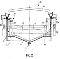
- An electrical power supply system provides for supplying on the upper and lower armatures 22 of the AC electrode 21 the current required for operation through suitable bars or cables 34, as schematically shown in figure 2 .
- the surface preparation unit for metal strips processing lines 10, subject of the present invention is particularly advantageous for an alternating current process, wherein the electrical power supply system of the electrodes has particular new solutions.
- the electrical power supply system 34 provides for supplying onto the upper and lower armatures 22 of the AC electrode 21 the alternating current required for the operation, with a 180° phase shift between the upper and lower armature.
- the upper and lower armatures 22 of each pair of electrodes 21 are shielded between each other, in the parts not involved in the passage of the strip, due to the interposition of plastic shields 35 which contribute to support them in the position parallel to the strip preventing direct electrical contact thereof.
- the electrical power supply system of the alternating current electrodes 34 is obtained in such a manner that all the electrode cells 20 are always supplied with phase voltage with respect to each other, in such a manner that all the armatures 22 of the electrodes 21 are polarized having the same phase, and this regardless of the practical embodiment of the power supply.
- Solutions based on single-phase transformers, each operating on only one phase of the electrical power supply network, followed by current regulators or, as preferred solution, on three-phase current rectifiers energising a common DC bar followed by inverters which, without unbalanced loads between the phases of the electrical power supply network, guarantee the control of the frequency and the waveform of the AC current used, may be mentioned as non-limiting examples of power supply.
- the voltages on the upper and lower armatures 22 are asymmetric with respect to each other, but in phase with respect to the upper and lower armatures 22 of an adjacent cell 20.
- the strip 11 shall preferably be connected to earthing rollers (not shown).
- the power supply system operates regardless of the network voltage allowing an ideal choice, depending on the process performed in the tank, the required frequencies and the waveforms.
- the power supply lines for supplying one phase and the power supply lines for supplying the opposite phase are preferably positioned on opposite sides of the tank 12, as illustrated in figure 2 .
- suitable insulation materials shield and insulate the sections supplied in the tank 12 guaranteeing separate supply of two upper and lower electrodes 21 with safety, reliability and efficiency functions comparable to those of traditional tanks supplied in DC.
- the surface preparation unit for metal strips processing lines subject of the present invention has the advantage of optimising the efficiency of the process regardless of the type of power supply, entirely in alternating current, entirely in direct current or partially in alternating current and in direct current, thus also disposing the high production of sludge and gases typical of such processes.
- the dispersion of current is advantageously reduced - with the ensuing improved energy saving - in the surface preparation unit for metal strips processing lines according to the invention.
- a preferred configuration in conditions of combined power supply, provides for the arrangement of electrodes according to one or more groups of AC electrodes arranged at the inlet of the tank 12 with respect to the direction of movement of the strip, followed by one or more groups of DC electrodes in such a manner to guarantee a high descaling action with ideal conditions for finishing the strip.
- the configuration of the tank may also be advantageously adapted to the required construction geometries.
- the structure of the surface preparation unit advantageously improves the detachment of the waste material from the strip, gaseous and solid, the moving away thereof from the "gap" and the subsequent removal from the tank.
Landscapes
- Chemical & Material Sciences (AREA)
- Engineering & Computer Science (AREA)
- Chemical Kinetics & Catalysis (AREA)
- Electrochemistry (AREA)
- Materials Engineering (AREA)
- Metallurgy (AREA)
- Organic Chemistry (AREA)
- Automation & Control Theory (AREA)
- Electroplating Methods And Accessories (AREA)
- Electrolytic Production Of Metals (AREA)
- Chemically Coating (AREA)
Description
- The present invention refers to a surface preparation unit for metal strips processing lines. Hereinafter, the expression "surface preparation for metal strips" is used for indicating the descaling and/or pickling operations.
- The evolution of the metal strips processing lines has led to the development of more and more efficient processes especially regarding the surface preparation of the surfaces, i.e. descaling and pickling, more commonly of the direct current (DC), or alternating current (AC), less used, or combined alternating current/direct current (AC/DC) electrolyte type. This allowed reducing the number of tanks in the line and/or increasing the travel speed of the strip with a noticeable increase of the tonnage of material treated per time unit and a reduction of environmental impact in terms of lower use of harmful acid solutions, and energy consumptions as well as chemical reagents considering the same production.
- The greater efficiency provided by the new developed processes however did not have a parallel evolution of the environment in which the processes are implemented. In practice, the tanks are, conceptually, the same used conventionally in the electrolyte processes with lower efficiency. Thus, it is not possible to fully exploit the potential offered by such new processes, for example due to the accumulation of slag.
- In the conventional processes, slag, at amounts not particularly high, could be kept in suspension by agitating the bath and filtered alongside the electrolyte. The higher efficiency processes produce a higher amount thereof, of which an ever-higher amount, in form of sludge, is deposited at the tank bottom thus having a negative impact on the hydrodynamic characteristics of the system and requiring higher maintenance costs.
- From a purely electrical point of view, regardless of the more or less innovative materials used and the trajectories followed, the conventionally most commonly used configuration is that referred to as direct current (DC) "grid to grid". Therein, the strip, generally kept at a neutral potential, often "earthed", is submerged in a conductive solution (acid or neutral) and it passes through electrodes also submerged in the electrolyte. The electrodes, or electrode cells, formed by extended and continuous armatures facing the two larger surfaces of the strip, are generally kept at the same potential (positive - anodic or negative - cathodic). The strip, in these conditions, locally behaves like an armature having a sign opposite to that of the grids towards which it faces progressively. Such polarisation produces, on the metal surface beneath the scale itself, the "displacement" in the polarisation curve moving the surface of the strip to conditions of anodic dissolution or cathodic protection. Depending on the voltage and current values there occurs the dissociation of water with development of H2 or 02 on the surface of the strip.
- This alternation of anodes and cathodes reveals some considerable drawbacks.
- two contiguous electrodes are arranged at a practically double mutual potential difference with respect to that having the strip. In order to minimise the dispersed currents, i.e. the currents that pass directly between an anode and a cathode without traversing the strip, then the contiguous armatures should be physically moved away up to a distance much greater than the passage gap of the strip between the electrodes thus leaving large zones of the tank unused.
- The thinner the strip, the higher the impact of the effects due to the low conductibility. In practice, the strip behaves as a conductor between two successive armatures with different potential: the higher the resistance and the more the material facing the armature acquires an electrical potential proximal to that of the armature itself. This leads to the occurrence of surface currents that dissipate in heat part of the supplied energy due to the Joule effect.
- In order to counter such effects there is the tendency of increasing the energy supply, with the increase of the voltage applied to the electrodes, to the detriment of energy saving.
- The acid etching which represents the main action for the pickling process is neutralised when the surface of the strip acquires a cathodic polarisation: the so-called cathodic protection zone which prevents acid etching (HCl, H2SO4 or other acids) on the metal surface preventing the formation of soluble salts produced by the chemical pickling reaction. In practice, such process is interrupted in the zones of the strip facing the anodically polarized armatures.
- the strip is generally supported by only two rollers, or pairs of wringing rollers, arranged at the inlet and outlet of the tank. The span, even of considerable dimensions, for example tens of meters, may be described, with fair approximation, as a "catenary". However, this is true only in case of detectable shape defects, such as for example cambering, puckering on the edges etc, which are relatively common. The presence of such unevenness, with aim of avoiding dangerous short-circuits, requires that the distance between the armature and strip, called "gap", be much greater than, theoretically, strictly necessary. From the information above, the increase of such distance generates an increase of energy consumptions and an increase of the dimensions of the tank, both length-wise and height-wise.
- Furthermore, the conventional configuration of the armatures for the conventional tanks, which are of the horizontal strips type transverse to the direction of motion of the strip, implies serious restrictions regarding the removal of the materials generated by the process. Actually, in the lower gap the gases are accumulated at direct contact with the strip not allowing intimate, continuous and homogeneous contact between the metal and the electrolyte required for the electrolyte cleaning process while the undissolved phase of the scale may be accumulated on the armatures. As a matter of fact, the maximum agitation of the bath is on the strip subjected to movement, at a position relatively distant from the planes of the cells thus negatively contributing to the electric conduction. The situation is identical in the upper gap, with the gases (H2 and 02) not being easy to evacuate near the armatures and the slag which could accumulate in the central area of the strip.
- New processes, such as those, for example, described in patent application
WO 02/50344 A1 WO 02/086199 A2 - An object of the present invention is that of providing a surface preparation unit for metal strips processing lines for accommodating direct current, alternating current or combined alternating/direct current high efficiency electrolytic descaling and/or pickling processes.
- Another object of the present invention is that of providing a surface preparation unit for metal strips processing lines capable of disposing the high production of sludge and gas typical of the high efficiency electrolytic descaling and/or pickling processes.
- Another object of the present invention is that of providing a surface preparation unit for metal strips processing lines which is particularly simple and functional, with low costs.
- These objects according to the present invention are attained by providing a surface preparation unit for metal strips processing lines as outlined in claim 1.
- Further characteristics are provided for in the dependent claims.
- Characteristics and advantages of a surface preparation unit for metal strips processing lines according to the present invention shall be clearer from the description that follows, provided by way of non-limiting example, with reference to the attached drawings, wherein:
-
figure 1 is a side elevational view sectioned along a median plane of a surface preparation unit for metal strips processing lines according to the present invention; -
figure 2 is a schematic and enlarged transverse section of the unit offigure 1 obtained in the plane of line II-II. - With reference to the figures, a surface preparation unit for metal strips processing lines, generally indicated with 10 is shown.
- The unit comprises a
tank 12, through which astrip 11 to be treated is continuously fed in the direction of the arrow F and returned on a system for the suspension/submersion of the strip made up of a plurality of rollers. - The
tank 12 comprises amain treatment portion 12a, containing an electrolyte solution, and twoopposite end portions 12b respectively bearing aninput roller 13 and anoutput deflection roller 14, which may be coupled to a wringingroller 15. Theend portions 12b of thetank 12 are delimited by awall 16 for holding the electrolyte, the wall rising from a bottom wall of thetank 12. Theend portions 12b do not contain electrolyte but they contain avalve 18 at the bottom. -
Submersion rollers 19, which divert thestrip 11 beneath the free fluid surface of the electrolyte contained in thetank 12 are respectively arranged immediately downstream of theinput roller 13 and immediately upstream of theoutput roller 14, at each end of themain treatment portion 12a. - In the embodiment shown in
figure 1 , a partition roller 19', arranged at the centre of thetank 12, divides the path of thestrip 11 into twofree spans 100, each comprised between thesubmersion roller 19 and the partition roller 19'. - Each
free span 100 contains at least oneelectrode cell 20, made up of upper andlower electrodes 21 with respect to thestrip 11, comprising upper andlower armatures 22, facing the two larger surfaces of thestrip 11.Figure 1 shows twoelectrode cells 20 for eachfree span 100 spaced from each other in the longitudinal direction. - The expression upper or
lower electrode 21 is used to indicate the complete structure that bears a given polarity facing the strip, localized in thearmature 22 of theelectrode 21, including the mechanical support structure as well as the electric connection one. - Regardless of the dimension of the
tank 12, it is provided for that thefree span 100 between twosuccessive submersion rollers 19 be preferably comprised between 3.5 m and 7 m. - Hence, a
tank 12 shall be provided with only twosubmersion rollers 19 should the distance between centres thereof, i.e. thefree span 100 therebetween be limited between 3.5 and 7 m. Should it be larger, thetank 12 shall be provided withadditional submersion rollers 19, such as the partition rollers 19', in a number such to keep eachfree span 100 of the strip always preferably comprised between 3.5 and 7 m. - Through the analysis of the speeds and the return elastic aspects of the transverse form of the
strip 11, the Applicant actually identified that a modular arrangement geometry of theelectrode cells 20, having a 3.5 m pitch in case of asingle electrode cell 20 or 7 m pitch for twocontiguous electrode cells 20 regardless of the possible polarisation of theelectrodes 21, allows a quick adaptation of the project of thetank 12 to the required specific operating condition, guaranteeing, simultaneously, the maximum efficiency of thefree span 100 in terms of homogeneity of the electric field. - Such arrangement also allows defining, right from the preliminary step, the geometric parameters of the
tank 12, thus optimizing both the overall dimensions and the costs of the system. - The
tank 12, according to the present invention, may containelectrode cells 20 all of the direct current type, all of the alternating current type, otherwise it may contain both direct current and alternating current cells, depending on the specific needs of the descaling/pickling process to be performed on the strip. - The particular modular arrangement described above finds ideal application in the case of an alternating current power supply, but it may be applied in all configurations for the supply and composition of the
useable electrodes 21. - In particular, in case of use of power supply in alternating current, the partition rollers 19' arranged between two
free spans 100 lose most of their importance as electric separation elements, substantially solely maintaining the mechanical function of positioning, supporting and levelling the geometric defects of thestrip 11. - The position of the
submersion rollers 19, 19' ensures that all thearmatures 22 of theelectrodes 21 are entirely submerged in the electrolyte. - It is clear that the restriction regarding the length of the
free span 100, additionally to the fact that thesubmersion rollers 19, 19' have the effect of flattening possible puckerings on the edges of thestrip 11 and stabilizing the position thereof, allow keeping the diversion with respect to the reference "catenary", schematized infigure 1 with a dash and dot line, under control. This allows keeping the distances between thestrip 11 and theupper armature 22, called "upper gap", as well as between thestrip 11 and thelower armature 22, called "lower gap" low, to reduce electrical consumption. - In the embodiment shown in
figure 1 , thestrip 11, which reaches the lowest point at the partition roller 19', has - in longitudinal direction - a symmetric development inclined towards the centre of thetank 12. All the members that cooperate with the strip, i.e. the upper andlower armatures 22 and the bottom of the tank are arranged according to a development substantially parallel to the theoretical path of thestrip 11 in eachfree span 100. - In order to eliminate scale sludge accumulations on the
lower armatures 22 and gas on theupper armatures 22, thearmatures 22 have, according to a preferred embodiment, a discontinuous shape having passage slots. Preferably, also the structures on which thearmatures 22 are anchored have a discontinuous shape. - Such discontinuous shape is for example made as rectangular-shaped bars having smaller dimensions in the direction of motion of the
strip 11 or, alternatively, circular-shaped bars. The bars forming the armatures are spaced from each other to allow, through the gaps therebetween, the evacuation of the waste material thus countering the tendency of the sludge to deposit on the surfaces of thearmatures 22 of thelower electrodes 21 and the gas bubbles produced by the electrochemical reactions to aggregate on the surfaces of thearmature 22 of theupper electrodes 21. - In both cases, the discontinuity in the electrophysical properties of the electrolyte would alter the ideal homogeneous configuration of the flow lines of the electric field within the electrolyte between the armature and the strip with the rarefactions or accumulations random and unstable over time and hence ensuing loss of efficiency of the entire line.
- The discontinuous configuration of the bars forming the
lower armatures 22 allows an easier and more effective evacuation of solid products towards the bottom of thetank 12, hence in zones far from the agitation flows of the electrolyte. Analogously, a discontinuous configuration of the bars forming theupper armatures 22 facilitates the evacuation of the bubbles upwards beyond the surface of the liquid. - The ideal operating conditions are thus restored.
- The preferred embodiment with
bar armatures 22 also opens the possibility of using different materials which due to welding fragility or difficulty are poorly suitable for continuous applications typical of the conventional armatures. - Specifically, as shown in the figures, the discontinuous shape may be obtained, for example, similar to a slot interposed between two rectangular-shaped bars extended along the direction transverse with respect to that of the motion of the strip. Groups of slots thus define continuous armature sections having small linear dimensions that may be fixed through methods different from welding, such as for example through special fixing means (for example bolts).
- Furthermore, the discontinuous shape of the
armatures 22 allows alternating materials having different characteristics, possibly even different from each other incompatible in terms of electrochemical properties and/or weldability, combining and alternating conventional materials with other materials having specific features such as for example coated titanium or non-metal materials that may be more expensive. - In any case, the construction simplification due to the use of special fixing means improve the maintenance times and the intervention complexity allowing intervening only where required.
- Means for recirculating and agitating the electrolyte also guarantee the moving of the waste material, made up of gas from the lower surface of the strip and scales undissolved from the upper surface, away from the
strip 11. - The recirculation and agitation are actuated by means of a plurality of
inlet nozzles 23 for the return of the electrolyte, preferably arranged at eachelectrode cell 20 on the walls of thetank 12 in submerged position and substantially at thestrip 11, in particular at a position slightly lower with respect to the same. - Through the
return inlet nozzles 23, the high flow rate electrolyte, after reconditioning thereof, is introduced into thetank 12 at the "gaps", i.e. between thearmatures 22, in a direction coinciding with that of the strip 11 (in co-current flow), or in the opposite direction (in countercurrent flow), depending on the geometries of thetank 12. The required flow rate is obtained throughpumps 24 which may have high flow rate and low head or operating at normal head (about 35-45 m) that supply jet pumps. - The electrolyte may also be introduced into the tank through the
inlet mouths 25 arranged at the two ends of the tank above the free fluid surface of the electrolyte, allowing an increase of the wet surface. - At each
electrode cell 20 the bottom of thetank 12 is shaped to form ahopper 26 which ends withdevices 27 for evacuating the waste made up of the undissolved part of the scale, which deposits at the bottom like sludge. Theevacuation devices 27 are made in form of evacuation bottom outlets which connect - by means of valves - the bottom of eachhopper 26 with adischarge pipe 28, which is connected, in turn, with asystem 29 for treating the sludgy residue material incorporating the sludge. - The alternation of the
hoppers 26 generates different agitation speeds in the electrolyte. The levels closest to thestrip 11 are the most agitated ones, hence capable of maintaining more scales in suspension. As the distance from the strip progressively increases, the geometric shape of thehoppers 26 produces calm zones, in the electrolyte, which allow the release of the non-solubilised scaly material. Such material is accumulated at the bottom of eachhopper 26 producing sludge easily removable form thedischarge pipes 28. - As mentioned, the
hoppers 26, equivalent to the number ofelectrode cells 20, are provided withpipings 28 having a section such to allow to be alternatingly opened through solenoid valves managed by the system for automating the pickling in such a manner to discharge the sludge quickly without emptying thetank 12 itself. - The
tank 12 has anupper cover 30 entirely sealed and the gases produced by the clearing process as waste material, are evacuated through a plurality ofgas evacuation outlets 31 arranged at the sides of thecover 30 in proximity to the ends of thetank 12 and connected to afumes suctioning collector 32 which leads to thefumes reduction system 33. - The surface preparation unit for metal
strips processing lines 10, subject of the present invention, may be used in a descaling and pickling system regardless of whether a direct current, alternating current or combined direct/alternating current electrolyte process is used. An electrical power supply system provides for supplying on the upper andlower armatures 22 of theAC electrode 21 the current required for operation through suitable bars orcables 34, as schematically shown infigure 2 . - However, the surface preparation unit for metal
strips processing lines 10, subject of the present invention, is particularly advantageous for an alternating current process, wherein the electrical power supply system of the electrodes has particular new solutions. - In particular, the electrical
power supply system 34 provides for supplying onto the upper andlower armatures 22 of theAC electrode 21 the alternating current required for the operation, with a 180° phase shift between the upper and lower armature. - The upper and
lower armatures 22 of each pair ofelectrodes 21 are shielded between each other, in the parts not involved in the passage of the strip, due to the interposition ofplastic shields 35 which contribute to support them in the position parallel to the strip preventing direct electrical contact thereof. - The electrical power supply system of the alternating
current electrodes 34 is obtained in such a manner that all theelectrode cells 20 are always supplied with phase voltage with respect to each other, in such a manner that all thearmatures 22 of theelectrodes 21 are polarized having the same phase, and this regardless of the practical embodiment of the power supply. Solutions based on single-phase transformers, each operating on only one phase of the electrical power supply network, followed by current regulators or, as preferred solution, on three-phase current rectifiers energising a common DC bar followed by inverters which, without unbalanced loads between the phases of the electrical power supply network, guarantee the control of the frequency and the waveform of the AC current used, may be mentioned as non-limiting examples of power supply. - The voltages on the upper and
lower armatures 22 are asymmetric with respect to each other, but in phase with respect to the upper andlower armatures 22 of anadjacent cell 20. - Thus, regardless of the thickness of the material, the current shall always traverse the
strip 11 conferring it an average potential obviously very close to neutral. Thestrip 11 shall preferably be connected to earthing rollers (not shown). - Furthermore, it is clear that such design solution eliminates - right from the source - the occurrence of those currents in the direction of feeding of the
strip 11 and in the direction of the input branch of thestrip 11, which, in traditional "grid to grid" pickling, disperse considerable amounts of energy. - Lastly, through the preferred configuration, the power supply system operates regardless of the network voltage allowing an ideal choice, depending on the process performed in the tank, the required frequencies and the waveforms.
- Additionally, in the
electrical system 34 for supplying the alternatingcurrent electrodes 21, wherein the twoarmatures 22 of the same pair ofelectrodes 21 are supplied with currents phase-shifted by 180°, thus requiring to be supplied separately implying the increase of the risk of short circuit, the power supply lines for supplying one phase and the power supply lines for supplying the opposite phase are preferably positioned on opposite sides of thetank 12, as illustrated infigure 2 . - Furthermore, suitable insulation materials shield and insulate the sections supplied in the
tank 12 guaranteeing separate supply of two upper andlower electrodes 21 with safety, reliability and efficiency functions comparable to those of traditional tanks supplied in DC. - The surface preparation unit for metal strips processing lines subject of the present invention has the advantage of optimising the efficiency of the process regardless of the type of power supply, entirely in alternating current, entirely in direct current or partially in alternating current and in direct current, thus also disposing the high production of sludge and gases typical of such processes.
- In case of power supply in alternating current, the dispersion of current is advantageously reduced - with the ensuing improved energy saving - in the surface preparation unit for metal strips processing lines according to the invention.
- Furthermore, power supply in alternating current improves the descaling and pickling efficiency hence leading to the simplification of the system and a better performance considering the same average current density, the environmental impact in term of the hazardousness of the finished solutions or solutions to be recycled (reducing the use of pollutant acids) as well as, lastly, energy saving, given that it is capable of attaining similar cleaning levels with lower electrical energy consumption.
- In case of combined power supply, partially in alternating current and in direct current, the separation of the power supply lines described above in relation to power supply in alternating current contributes to improving safety and rejection of possible accidents and/or functional blocks of the
tank 12 due to short circuits. - A preferred configuration, in conditions of combined power supply, provides for the arrangement of electrodes according to one or more groups of AC electrodes arranged at the inlet of the
tank 12 with respect to the direction of movement of the strip, followed by one or more groups of DC electrodes in such a manner to guarantee a high descaling action with ideal conditions for finishing the strip. - The configuration of the tank may also be advantageously adapted to the required construction geometries.
- The optimisation of the "gaps", i.e. the distances between the armatures and the strip, allows reducing the intensity of the current that should traverse the strip with considerable energy saving.
- The structure of the surface preparation unit advantageously improves the detachment of the waste material from the strip, gaseous and solid, the moving away thereof from the "gap" and the subsequent removal from the tank.
- The surface preparation unit for metal strips processing lines thus conceived is susceptible to various modifications and variants, all falling within the invention; furthermore all the details may be replaced by technically equivalent elements. In practice the materials used, as well as the dimensions, may vary according to the technical requirements.
Claims (12)
- Surface preparation unit for metal strips processing lines comprising a tank (12), suitable to contain an electrolyte solution, a system for the suspension/submersion of a strip (11) to be treated, which is continuously fed in said tank (12) in longitudinal direction (F), a plurality of electrode cells (20) comprising upper and lower electrodes (21) respectively comprising upper and lower armatures (22) facing the two larger surfaces of the strip (11) and spaced from it by a spacing called "upper gap" and "lower gap" respectively, said electrodes (21) being connected to an electrical power supply system (34), said tank (12) being shaped at the bottom to form successive hoppers (26), said surface preparation unit being characterized in that at each of said electrode cells (20) there is provided one of said hoppers (26) which ends with devices (27) for evacuating the waste material in form of undissolved scale, which deposits at the bottom in form of sludge, said electrodes (21) having a discontinuous shape, said upper and lower armatures (22) of the electrodes being made up of a plurality of bars spaced from each other to form gaps there between for the evacuation of waste material in form of gas and scale sludges.
- Unit according to claim 1, characterised in that said system for the suspension/submersion of the strip comprises at least one input roller (13) and one output deflection roller (14), as well as at least one submersion roller (19) at each end, wherein said at least one submersion roller (19) at each end is respectively arranged downstream of the input roller (13) and upstream of the output deflection roller (14) to divert the strip (11) beneath the free fluid surface of the electrolyte contained in the tank (12), said submersion rollers (19) being spaced in such a manner as to provide a free span (100) comprised between 3.5 m and 7 m.
- Unit according to claim 2, characterised in that it comprises, for length values of the tank (12) exceeding 7 m, at least one further partition submersion roller (19') which divides the path of the strip (11) into at least two free spans (100), each containing at least one electrode cell (20).
- Unit according to claim 3, characterised in that in each free span (100) the bottom of the tank (12) and the upper and lower armatures (22) are arranged substantially parallel to the theoretical path of the strip (11) between the submersion rollers (19, 19').
- Unit according to any of the preceding claims, characterised in that said upper and lower armatures (22) of each pair of electrodes (21) are shielded between each other by interposing plastic shields (35) which support them in the position parallel to the strip (11) preventing direct electrical contact thereof.
- Unit according to any of the preceding claims, characterised in that it comprises means for recirculating and agitating the electrolyte, said means being suitable to facilitate moving waste materials away from the strip (11), the waste material being made up of gas from the surface below the strip (11) and scale sludge from the upper surface.
- Unit according to claim 6, characterised in that said means for recirculating and agitating the electrolyte comprise a plurality of inlet nozzles (23) for returning the electrolyte at high flow rate, said return inlet nozzles (23) being arranged in submerged position at each electrode cell (20) substantially at the strip level (11).
- Unit according to claim 1, characterised in that said means (27) for evacuating waste material in form of undissolved scale comprise a bottom evacuation opening which connects - by means of a valve - said hopper (26) to a discharge pipe (28) connected, in turn, with a system (29) for treating sludgy residue material containing scale.
- Unit according to claim 8, characterised in that said valves are solenoid valves which alternatively open each hopper (26) in such a manner to discharge the sludge quickly without emptying the tank (12).
- Unit according to any one of the preceding claims, characterised in that said system for supplying electrical power to the electrodes (34) supplies said upper and lower armatures (22) of each cell (20) of electrodes (21) in alternating current, said alternating current being phase-shifted by 180° therebetween, all electrode cells always being supplied with in-phase voltage.
- Unit according to claim 10, characterised in that said electrical power supply (34) comprises single-phase transformers, each operating on only one phase of the electrical power supply network, followed by current regulators.
- Unit according to claim 10, characterised in that said electrical power supply (34) comprises three-phase current rectifiers energizing a direct current bar and followed by inverters which, avoiding unbalanced loads between the phases of the electrical power supply network, guarantee controlling the frequency and waveform of the AC current, regardless of the supply voltage.
Applications Claiming Priority (2)
| Application Number | Priority Date | Filing Date | Title |
|---|---|---|---|
| ITMI2009A001681A IT1395853B1 (en) | 2009-09-30 | 2009-09-30 | SURFACE PREPARATION GROUP FOR METALLIC TAPE PRODUCTION LINES |
| PCT/IB2010/002402 WO2011039596A1 (en) | 2009-09-30 | 2010-09-24 | Surface preparation unit for metal strips processing lines |
Publications (2)
| Publication Number | Publication Date |
|---|---|
| EP2483459A1 EP2483459A1 (en) | 2012-08-08 |
| EP2483459B1 true EP2483459B1 (en) | 2017-06-14 |
Family
ID=42184098
Family Applications (1)
| Application Number | Title | Priority Date | Filing Date |
|---|---|---|---|
| EP10776141.3A Active EP2483459B1 (en) | 2009-09-30 | 2010-09-24 | Surface preparation unit for metal strips processing lines |
Country Status (4)
| Country | Link |
|---|---|
| EP (1) | EP2483459B1 (en) |
| CN (1) | CN102713023B (en) |
| IT (1) | IT1395853B1 (en) |
| WO (1) | WO2011039596A1 (en) |
Families Citing this family (5)
| Publication number | Priority date | Publication date | Assignee | Title |
|---|---|---|---|---|
| ITMI20130493A1 (en) | 2013-03-29 | 2014-09-30 | Tenova Spa | METHOD TO PROCESS THE SURFACE OF A STAINLESS STEEL LAMINATE IN A CONTINUOUS SOLFORIC ACID SOLUTION |
| ITMI20130494A1 (en) | 2013-03-29 | 2014-09-30 | Tenova Spa | METHOD OF TREATING CONTINUOUSLY THE SURFACE OF A STAINLESS STEEL LAMINATE IN A CHLORIDRID ACID-BASED SOLUTION |
| ITMI20130497A1 (en) | 2013-03-29 | 2014-09-30 | Tenova Spa | EQUIPMENT FOR THE CONTINUOUS SURFACE ELECTROLYTIC TREATMENT OF METALLIC SEMI-FINISHED PRODUCTS, IN PARTICULAR FLAT METALLIC SEMI-FINISHED PRODUCTS. |
| CN104928738B (en) * | 2015-05-21 | 2017-04-19 | 中国科学院山西煤炭化学研究所 | Continuous metal electroplating method and device for carbon fiber tows |
| CN105220213A (en) * | 2015-10-24 | 2016-01-06 | 本钢不锈钢冷轧丹东有限责任公司 | Neutral salt electrolysis groove |
Family Cites Families (8)
| Publication number | Priority date | Publication date | Assignee | Title |
|---|---|---|---|---|
| US4859298A (en) * | 1988-12-07 | 1989-08-22 | Chemcut Corporation | Process and apparatus for electrolytically removing protective layers from sheet metal substrate |
| CN2148766Y (en) * | 1992-11-04 | 1993-12-08 | 鞍山钢铁公司 | Metal prolduct surface electrochemical continuous pretreating apparatus |
| AT405060B (en) * | 1996-04-12 | 1999-05-25 | Andritz Patentverwaltung | METHOD AND DEVICE FOR ELECTROLYTICALLY TREATING CONTINUOUS GOODS |
| JP3357032B2 (en) * | 1999-12-21 | 2002-12-16 | ハセ技研株式会社 | Plating apparatus and plating method |
| IT1318919B1 (en) * | 2000-09-22 | 2003-09-19 | Danieli Hi Tech Gmbh | PROCESS AND DEVICE FOR SURFACE ELECTROLYTIC TREATMENT OF METAL TAPES. |
| CN1231615C (en) | 2000-12-18 | 2005-12-14 | 材料开发中心股份公司 | Continuous electrolytic pickling and descaling of carbon steel and stainless steel |
| ITRM20010223A1 (en) | 2001-04-24 | 2002-10-24 | Ct Sviluppo Materiali Spa | METHOD FOR THE CONTINUOUS ELECTROLYTIC DESCRIPTION OF STAINLESS STEELS IN THE PRESENCE OF INDIRECT EFFECTS OF THE CURRENT PASSAGE. |
| AT413707B (en) * | 2004-07-19 | 2006-05-15 | Voest Alpine Ind Anlagen | METHOD AND DEVICE FOR METALING |
-
2009
- 2009-09-30 IT ITMI2009A001681A patent/IT1395853B1/en active
-
2010
- 2010-09-24 CN CN201080042867.3A patent/CN102713023B/en active Active
- 2010-09-24 WO PCT/IB2010/002402 patent/WO2011039596A1/en not_active Ceased
- 2010-09-24 EP EP10776141.3A patent/EP2483459B1/en active Active
Also Published As
| Publication number | Publication date |
|---|---|
| EP2483459A1 (en) | 2012-08-08 |
| CN102713023B (en) | 2015-12-16 |
| CN102713023A (en) | 2012-10-03 |
| IT1395853B1 (en) | 2012-10-26 |
| ITMI20091681A1 (en) | 2011-04-01 |
| WO2011039596A1 (en) | 2011-04-07 |
Similar Documents
| Publication | Publication Date | Title |
|---|---|---|
| US7309408B2 (en) | Industrial wastewater treatment and metals recovery apparatus | |
| EP1115908B1 (en) | Natural gas-assisted steam electrolyzer | |
| US4755305A (en) | Continuous dewatering method | |
| CN100591629C (en) | A high-frequency pulse electrochemical wastewater treatment process and its device | |
| WO2011039596A1 (en) | Surface preparation unit for metal strips processing lines | |
| EP2150500B1 (en) | An electrocoagulation cell | |
| AU2008291662B2 (en) | Method for operating copper electrolysis cells | |
| JPH0839074A (en) | Method and apparatus for treating industrial wastewater by electrolysis | |
| US3650935A (en) | Apparatus for electrolytic surface treatment | |
| CN102010037A (en) | Design scheme of standardized electric flocculation equipment | |
| CN203065598U (en) | Smelting equipment | |
| CN101516785A (en) | Method for removing hazardous substances from liquids and device for carrying out the method | |
| PL96577B1 (en) | METHOD OF ELECTROLYSIS OF COLORED METALS AND DEVICE FOR ELECTROLYSIS OF COLORED METALS | |
| AU2005263476A1 (en) | Method and device for descaling metals | |
| JPS6121319B2 (en) | ||
| IT201800009628A1 (en) | PROCESS AND EQUIPMENT OF ELECTROCOAGULATION FOR TREATMENTS OF PURIFICATION OF CONTAMINATED LIQUIDS | |
| SU1000406A1 (en) | Electrolyzer for purifying effluents | |
| KR200227263Y1 (en) | Inclined settling tank for maximal osculation area | |
| CN208980387U (en) | A kind of adjustable wastewater treatment electrolytic cell of pole span | |
| KR200223757Y1 (en) | Sewage and wastewater treatment system using electrolysis and inclined settler | |
| KR20070031981A (en) | Wastewater treatment device using electrode plate fixing device and its manufacturing method | |
| KR101052606B1 (en) | Electrolysis Line Circulation System for Purification of Abandoned Mine Mine Water | |
| CN222574407U (en) | Electrochemical sewage treatment device | |
| CN115976578B (en) | A cationic membrane packed bed electrode reactor for wet metal recovery and its recovery method | |
| KR20080104925A (en) | Electrolysis Reactor Using Conversion Membrane |
Legal Events
| Date | Code | Title | Description |
|---|---|---|---|
| PUAI | Public reference made under article 153(3) epc to a published international application that has entered the european phase |
Free format text: ORIGINAL CODE: 0009012 |
|
| 17P | Request for examination filed |
Effective date: 20120307 |
|
| AK | Designated contracting states |
Kind code of ref document: A1 Designated state(s): AL AT BE BG CH CY CZ DE DK EE ES FI FR GB GR HR HU IE IS IT LI LT LU LV MC MK MT NL NO PL PT RO SE SI SK SM TR |
|
| DAX | Request for extension of the european patent (deleted) | ||
| GRAP | Despatch of communication of intention to grant a patent |
Free format text: ORIGINAL CODE: EPIDOSNIGR1 |
|
| STAA | Information on the status of an ep patent application or granted ep patent |
Free format text: STATUS: GRANT OF PATENT IS INTENDED |
|
| INTG | Intention to grant announced |
Effective date: 20170104 |
|
| GRAS | Grant fee paid |
Free format text: ORIGINAL CODE: EPIDOSNIGR3 |
|
| GRAA | (expected) grant |
Free format text: ORIGINAL CODE: 0009210 |
|
| STAA | Information on the status of an ep patent application or granted ep patent |
Free format text: STATUS: THE PATENT HAS BEEN GRANTED |
|
| AK | Designated contracting states |
Kind code of ref document: B1 Designated state(s): AL AT BE BG CH CY CZ DE DK EE ES FI FR GB GR HR HU IE IS IT LI LT LU LV MC MK MT NL NO PL PT RO SE SI SK SM TR |
|
| REG | Reference to a national code |
Ref country code: GB Ref legal event code: FG4D |
|
| REG | Reference to a national code |
Ref country code: CH Ref legal event code: EP Ref country code: AT Ref legal event code: REF Ref document number: 901037 Country of ref document: AT Kind code of ref document: T Effective date: 20170615 |
|
| REG | Reference to a national code |
Ref country code: IE Ref legal event code: FG4D |
|
| REG | Reference to a national code |
Ref country code: DE Ref legal event code: R096 Ref document number: 602010042987 Country of ref document: DE |
|
| REG | Reference to a national code |
Ref country code: FR Ref legal event code: PLFP Year of fee payment: 8 |
|
| REG | Reference to a national code |
Ref country code: NL Ref legal event code: FP |
|
| REG | Reference to a national code |
Ref country code: SE Ref legal event code: TRGR |
|
| REG | Reference to a national code |
Ref country code: LT Ref legal event code: MG4D |
|
| PG25 | Lapsed in a contracting state [announced via postgrant information from national office to epo] |
Ref country code: HR Free format text: LAPSE BECAUSE OF FAILURE TO SUBMIT A TRANSLATION OF THE DESCRIPTION OR TO PAY THE FEE WITHIN THE PRESCRIBED TIME-LIMIT Effective date: 20170614 Ref country code: GR Free format text: LAPSE BECAUSE OF FAILURE TO SUBMIT A TRANSLATION OF THE DESCRIPTION OR TO PAY THE FEE WITHIN THE PRESCRIBED TIME-LIMIT Effective date: 20170915 Ref country code: NO Free format text: LAPSE BECAUSE OF FAILURE TO SUBMIT A TRANSLATION OF THE DESCRIPTION OR TO PAY THE FEE WITHIN THE PRESCRIBED TIME-LIMIT Effective date: 20170914 Ref country code: LT Free format text: LAPSE BECAUSE OF FAILURE TO SUBMIT A TRANSLATION OF THE DESCRIPTION OR TO PAY THE FEE WITHIN THE PRESCRIBED TIME-LIMIT Effective date: 20170614 Ref country code: ES Free format text: LAPSE BECAUSE OF FAILURE TO SUBMIT A TRANSLATION OF THE DESCRIPTION OR TO PAY THE FEE WITHIN THE PRESCRIBED TIME-LIMIT Effective date: 20170614 |
|
| REG | Reference to a national code |
Ref country code: AT Ref legal event code: MK05 Ref document number: 901037 Country of ref document: AT Kind code of ref document: T Effective date: 20170614 |
|
| PG25 | Lapsed in a contracting state [announced via postgrant information from national office to epo] |
Ref country code: BG Free format text: LAPSE BECAUSE OF FAILURE TO SUBMIT A TRANSLATION OF THE DESCRIPTION OR TO PAY THE FEE WITHIN THE PRESCRIBED TIME-LIMIT Effective date: 20170914 Ref country code: LV Free format text: LAPSE BECAUSE OF FAILURE TO SUBMIT A TRANSLATION OF THE DESCRIPTION OR TO PAY THE FEE WITHIN THE PRESCRIBED TIME-LIMIT Effective date: 20170614 |
|
| PG25 | Lapsed in a contracting state [announced via postgrant information from national office to epo] |
Ref country code: RO Free format text: LAPSE BECAUSE OF FAILURE TO SUBMIT A TRANSLATION OF THE DESCRIPTION OR TO PAY THE FEE WITHIN THE PRESCRIBED TIME-LIMIT Effective date: 20170614 Ref country code: AT Free format text: LAPSE BECAUSE OF FAILURE TO SUBMIT A TRANSLATION OF THE DESCRIPTION OR TO PAY THE FEE WITHIN THE PRESCRIBED TIME-LIMIT Effective date: 20170614 Ref country code: EE Free format text: LAPSE BECAUSE OF FAILURE TO SUBMIT A TRANSLATION OF THE DESCRIPTION OR TO PAY THE FEE WITHIN THE PRESCRIBED TIME-LIMIT Effective date: 20170614 Ref country code: SK Free format text: LAPSE BECAUSE OF FAILURE TO SUBMIT A TRANSLATION OF THE DESCRIPTION OR TO PAY THE FEE WITHIN THE PRESCRIBED TIME-LIMIT Effective date: 20170614 |
|
| PG25 | Lapsed in a contracting state [announced via postgrant information from national office to epo] |
Ref country code: IS Free format text: LAPSE BECAUSE OF FAILURE TO SUBMIT A TRANSLATION OF THE DESCRIPTION OR TO PAY THE FEE WITHIN THE PRESCRIBED TIME-LIMIT Effective date: 20171014 Ref country code: PL Free format text: LAPSE BECAUSE OF FAILURE TO SUBMIT A TRANSLATION OF THE DESCRIPTION OR TO PAY THE FEE WITHIN THE PRESCRIBED TIME-LIMIT Effective date: 20170614 Ref country code: SM Free format text: LAPSE BECAUSE OF FAILURE TO SUBMIT A TRANSLATION OF THE DESCRIPTION OR TO PAY THE FEE WITHIN THE PRESCRIBED TIME-LIMIT Effective date: 20170614 |
|
| REG | Reference to a national code |
Ref country code: DE Ref legal event code: R097 Ref document number: 602010042987 Country of ref document: DE |
|
| PLBE | No opposition filed within time limit |
Free format text: ORIGINAL CODE: 0009261 |
|
| STAA | Information on the status of an ep patent application or granted ep patent |
Free format text: STATUS: NO OPPOSITION FILED WITHIN TIME LIMIT |
|
| PG25 | Lapsed in a contracting state [announced via postgrant information from national office to epo] |
Ref country code: DK Free format text: LAPSE BECAUSE OF FAILURE TO SUBMIT A TRANSLATION OF THE DESCRIPTION OR TO PAY THE FEE WITHIN THE PRESCRIBED TIME-LIMIT Effective date: 20170614 |
|
| REG | Reference to a national code |
Ref country code: CH Ref legal event code: PL |
|
| 26N | No opposition filed |
Effective date: 20180315 |
|
| GBPC | Gb: european patent ceased through non-payment of renewal fee |
Effective date: 20170924 |
|
| PG25 | Lapsed in a contracting state [announced via postgrant information from national office to epo] |
Ref country code: MC Free format text: LAPSE BECAUSE OF FAILURE TO SUBMIT A TRANSLATION OF THE DESCRIPTION OR TO PAY THE FEE WITHIN THE PRESCRIBED TIME-LIMIT Effective date: 20170614 |
|
| REG | Reference to a national code |
Ref country code: IE Ref legal event code: MM4A |
|
| PG25 | Lapsed in a contracting state [announced via postgrant information from national office to epo] |
Ref country code: LU Free format text: LAPSE BECAUSE OF NON-PAYMENT OF DUE FEES Effective date: 20170924 |
|
| PG25 | Lapsed in a contracting state [announced via postgrant information from national office to epo] |
Ref country code: CH Free format text: LAPSE BECAUSE OF NON-PAYMENT OF DUE FEES Effective date: 20170930 Ref country code: IE Free format text: LAPSE BECAUSE OF NON-PAYMENT OF DUE FEES Effective date: 20170924 Ref country code: GB Free format text: LAPSE BECAUSE OF NON-PAYMENT OF DUE FEES Effective date: 20170924 Ref country code: LI Free format text: LAPSE BECAUSE OF NON-PAYMENT OF DUE FEES Effective date: 20170930 |
|
| PG25 | Lapsed in a contracting state [announced via postgrant information from national office to epo] |
Ref country code: SI Free format text: LAPSE BECAUSE OF FAILURE TO SUBMIT A TRANSLATION OF THE DESCRIPTION OR TO PAY THE FEE WITHIN THE PRESCRIBED TIME-LIMIT Effective date: 20170614 |
|
| REG | Reference to a national code |
Ref country code: FR Ref legal event code: PLFP Year of fee payment: 9 |
|
| PG25 | Lapsed in a contracting state [announced via postgrant information from national office to epo] |
Ref country code: MT Free format text: LAPSE BECAUSE OF NON-PAYMENT OF DUE FEES Effective date: 20170924 |
|
| PG25 | Lapsed in a contracting state [announced via postgrant information from national office to epo] |
Ref country code: HU Free format text: LAPSE BECAUSE OF FAILURE TO SUBMIT A TRANSLATION OF THE DESCRIPTION OR TO PAY THE FEE WITHIN THE PRESCRIBED TIME-LIMIT; INVALID AB INITIO Effective date: 20100924 |
|
| PG25 | Lapsed in a contracting state [announced via postgrant information from national office to epo] |
Ref country code: CY Free format text: LAPSE BECAUSE OF NON-PAYMENT OF DUE FEES Effective date: 20170614 |
|
| PG25 | Lapsed in a contracting state [announced via postgrant information from national office to epo] |
Ref country code: MK Free format text: LAPSE BECAUSE OF FAILURE TO SUBMIT A TRANSLATION OF THE DESCRIPTION OR TO PAY THE FEE WITHIN THE PRESCRIBED TIME-LIMIT Effective date: 20170614 |
|
| PG25 | Lapsed in a contracting state [announced via postgrant information from national office to epo] |
Ref country code: TR Free format text: LAPSE BECAUSE OF FAILURE TO SUBMIT A TRANSLATION OF THE DESCRIPTION OR TO PAY THE FEE WITHIN THE PRESCRIBED TIME-LIMIT Effective date: 20170614 |
|
| PG25 | Lapsed in a contracting state [announced via postgrant information from national office to epo] |
Ref country code: PT Free format text: LAPSE BECAUSE OF FAILURE TO SUBMIT A TRANSLATION OF THE DESCRIPTION OR TO PAY THE FEE WITHIN THE PRESCRIBED TIME-LIMIT Effective date: 20170614 |
|
| PG25 | Lapsed in a contracting state [announced via postgrant information from national office to epo] |
Ref country code: AL Free format text: LAPSE BECAUSE OF FAILURE TO SUBMIT A TRANSLATION OF THE DESCRIPTION OR TO PAY THE FEE WITHIN THE PRESCRIBED TIME-LIMIT Effective date: 20170614 |
|
| P01 | Opt-out of the competence of the unified patent court (upc) registered |
Effective date: 20230505 |
|
| PGFP | Annual fee paid to national office [announced via postgrant information from national office to epo] |
Ref country code: FI Payment date: 20250925 Year of fee payment: 16 |
|
| PGFP | Annual fee paid to national office [announced via postgrant information from national office to epo] |
Ref country code: DE Payment date: 20250929 Year of fee payment: 16 |
|
| PGFP | Annual fee paid to national office [announced via postgrant information from national office to epo] |
Ref country code: NL Payment date: 20250926 Year of fee payment: 16 Ref country code: IT Payment date: 20250919 Year of fee payment: 16 |
|
| PGFP | Annual fee paid to national office [announced via postgrant information from national office to epo] |
Ref country code: BE Payment date: 20250929 Year of fee payment: 16 |
|
| PGFP | Annual fee paid to national office [announced via postgrant information from national office to epo] |
Ref country code: FR Payment date: 20250925 Year of fee payment: 16 |
|
| PGFP | Annual fee paid to national office [announced via postgrant information from national office to epo] |
Ref country code: SE Payment date: 20250927 Year of fee payment: 16 |
|
| PGFP | Annual fee paid to national office [announced via postgrant information from national office to epo] |
Ref country code: CZ Payment date: 20250908 Year of fee payment: 16 |