EP2483090B1 - Suction unit of a vehicle's air conditioning system - Google Patents
Suction unit of a vehicle's air conditioning system Download PDFInfo
- Publication number
- EP2483090B1 EP2483090B1 EP10767968.0A EP10767968A EP2483090B1 EP 2483090 B1 EP2483090 B1 EP 2483090B1 EP 10767968 A EP10767968 A EP 10767968A EP 2483090 B1 EP2483090 B1 EP 2483090B1
- Authority
- EP
- European Patent Office
- Prior art keywords
- air
- canal
- suction unit
- air flow
- unit according
- Prior art date
- Legal status (The legal status is an assumption and is not a legal conclusion. Google has not performed a legal analysis and makes no representation as to the accuracy of the status listed.)
- Revoked
Links
Images
Classifications
-
- B—PERFORMING OPERATIONS; TRANSPORTING
- B60—VEHICLES IN GENERAL
- B60H—ARRANGEMENTS OF HEATING, COOLING, VENTILATING OR OTHER AIR-TREATING DEVICES SPECIALLY ADAPTED FOR PASSENGER OR GOODS SPACES OF VEHICLES
- B60H1/00—Heating, cooling or ventilating devices
- B60H1/00007—Combined heating, ventilating, or cooling devices
- B60H1/00021—Air flow details of HVAC devices
- B60H1/00028—Constructional lay-out of the devices in the vehicle
-
- B—PERFORMING OPERATIONS; TRANSPORTING
- B60—VEHICLES IN GENERAL
- B60H—ARRANGEMENTS OF HEATING, COOLING, VENTILATING OR OTHER AIR-TREATING DEVICES SPECIALLY ADAPTED FOR PASSENGER OR GOODS SPACES OF VEHICLES
- B60H1/00—Heating, cooling or ventilating devices
- B60H1/00507—Details, e.g. mounting arrangements, desaeration devices
- B60H1/00557—Details of ducts or cables
- B60H1/00564—Details of ducts or cables of air ducts
-
- B—PERFORMING OPERATIONS; TRANSPORTING
- B60—VEHICLES IN GENERAL
- B60H—ARRANGEMENTS OF HEATING, COOLING, VENTILATING OR OTHER AIR-TREATING DEVICES SPECIALLY ADAPTED FOR PASSENGER OR GOODS SPACES OF VEHICLES
- B60H1/00—Heating, cooling or ventilating devices
- B60H1/24—Ventilating devices where the heating or cooling is irrelevant
- B60H1/241—Ventilating devices where the heating or cooling is irrelevant characterised by the location of ventilation devices in the vehicle
- B60H1/242—Ventilating devices where the heating or cooling is irrelevant characterised by the location of ventilation devices in the vehicle located in the front area
-
- B—PERFORMING OPERATIONS; TRANSPORTING
- B60—VEHICLES IN GENERAL
- B60H—ARRANGEMENTS OF HEATING, COOLING, VENTILATING OR OTHER AIR-TREATING DEVICES SPECIALLY ADAPTED FOR PASSENGER OR GOODS SPACES OF VEHICLES
- B60H1/00—Heating, cooling or ventilating devices
- B60H1/00007—Combined heating, ventilating, or cooling devices
- B60H1/00021—Air flow details of HVAC devices
- B60H2001/00078—Assembling, manufacturing or layout details
- B60H2001/00085—Assembling, manufacturing or layout details of air intake
Definitions
- This invention is a suction unit of a vehicle's air conditioning system.
- the suction unit of a vehicle's air conditioning system commonly is a self-contained and partly preassembled unit via which the air from the environment is absorbed, filtered and then transported to the air conditioning system using a fan.
- a fan In case of high humidity it is beneficial and desirable to reduce the humidity in order to avoid moisture from entering the fan motor.
- the generic document EP 1 642 755 A1 has shown that it is vital to provide a water separation chamber for humidity reduction upstream from the fan housing.
- the water separation chamber consists of half of a space, which is separated by a wall running from the top to almost the bottom of the space. This forms a U-shaped canal, half of which forms the water separation chamber, in which condensation is collected. Via the other half, drier air flows towards the fan.
- An other suction unit of a vehicle's air conditioning system is known from DE 33 30 951 A1 , which is considered as the closest prior art. It discloses a suction unit of a vehicle's air conditioning system, including an air flow canal, which has a suction opening for fresh air, as well as a fan housing, which possesses an air inlet and an air outlet, wherein the air flow canal runs from the suction opening to the air inlet, and is limited by a canal wall and enfolded by a water separation chamber, in which water drops are collected that form due to the moist air flowing through the water separation chamber, wherein this water separation chamber is limited by canal wall segments at which the condensation is collected, and at the same time, an air outlet of the water separation chamber is directly limited by an air filter upstream from the fan housing, according to all the features of the preamble of claim 1.
- the purpose of the present invention is to further simplify the above mentioned device without compromising its dehydrating properties, as well as reduction of space of the suction unit.
- an outlet ending of the water separation chamber is limited directly through an air filter, which is positioned upstream from the fan.
- the inventors of this suction unit omitted the intermediate canal between the air filter and the water separation chamber, so that the air filter can approach the water separation chamber.
- the air flow canal includes an air recirculation flap upstream said air filter. Therefore, according to the invention, the result is a reduced installation space for the suction unit.
- the air filter is integrated either in a horizontal or a vertical manner regarding the assembly condition of the suction unit in the vehicle.
- the wall of the air flow canal directly adjoins to the fan or is formed to the fan in segments.
- the preferred means for the condensation of the waterdrops from the moist air exclusively are the outer walls that build the segments of the air flow canal.
- canal segments which are used for the collection of condensated water, possess a rougher surface than its vicinal surfaces of the canal wall, so that waterdrops can easily deposit to these segments.
- Another option for the drops to deposit to certain segments of the canal wall is that the segments possess a rib-like pattern.
- the canal wall segments for water condensation can also be furnished with a wire grid or wire meshwork. This aids the formation of waterdrops as well.
- the flow canal can deflect the flow direction of the incoming environmental air between the suction opening and the air inlet by at least 90°, preferably by at least 150°, so that a "U" forms. This serves the space-saving embodiment of this suction unit.
- the air flow canal suction opening for recirculating air should, according to the assembly condition of the suction unit in the vehicle, be positioned at the highest point of the air flow canal or in the vicinity of a portion of the air flow canal, which shows an air flow component directed against gravity.
- These embodiments prevent condensation water to enter into the attached recirculating air canal by travelling through the suction opening.
- the filter itself should preferably be positioned in the upstream part, that is in the part that is positioned after the lowest point of the suction unit in regards to flow in order for as little moisture as possible to reach the air filter.
- the suction unit is completely preassembled and can be installed in the vehicle as is.
- the water separation chamber should feature a drainage outlet for the water at its lowest point.
- more than 30%, especially more than 50% of the air flow canal, which reaches from the suction opening to the air filter, should be aligned downwards as consistent with gravity. This is to ensure the certain separation of the water contained in the fresh air using gravity (and possibly centrifugal force).
- the motor should preferably be positioned level with the suction opening of the unit. This will cause a U-shape of the air flow canal in regards to the flow progression.
- the air flow canal includes an air recirculation flap with a sealable suction opening for recirculating air, said air recirculation flap being arranged upstream the air filter, which will allow recirculated air to re-enter into the suction unit when open.
- the air flow canal can be U-shaped with the fan housing positioned below the suction opening.
- the filter is installed vertically and the water separation chamber forms the centre journal (vertical journal) of the horizontal U.
- FIG. 1 shows a vehicle with noncontinuous lines, while reference numeral 10 symbolizes the fire wall.
- the vehicle features an air conditioning system 12, also called HVAC unit, which facilitates the ventilation, heating and air conditioning of the vehicle.
- a suction unit 14 provides the supply of fresh air inside the vehicle, which can be available completely preassembled.
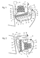
- the suction unit 14 encompasses an air flow canal 16, which features a suction opening 18 for fresh air, that is recirculated air.
- This air flow canal 16 is formed by the outer housing 20 of the suction unit.
- the air flow canal 16 possesses several segments, namely a first segment 22, which vertically extends downwards from the suction opening 18, a centre segment 24, which forms a horizontal segment of the air flow canal 16, as well as a rising third segment 26, which comes to an end in a fan housing 28 with an air inlet 29.
- the fan housing 28 contains a fan motor 30 as well as a fan wheel 32, which is powered by the fan motor. These elements draw in fresh air and transport it to the vehicle's air conditioning system 12 via an air outlet 31 (see arrows).
- the air flow canal 16 is intended to have an air filter after the horizontal or centre segment 24.
- This air filter has the reference numeral 34.
- the air filter 34 is primarily aligned horizontally.
- An air recirculation flap 36 is positioned upstream of the air filter 34 and makes it possible for the air circulation to reach the inside of the vehicle.
- the air flow canal 16 is limited by a canal wall 38, which, for the most part, is completely formed by the outer housing 20.
- the canal wall segments 40 which are limited by a noncontinuous line on the outside and a continuous line on the inside, form segments, which limit the so-called water separation chamber 42.
- This water separation chamber 42 is, in a manner of speaking, part of the air flow canal 16, in which waterdrops from the incoming fresh air are collected by depositing at the canal wall segments 40.
- These canal wall segments 40 attract condensation, which then is collected at the lowest point of the air flow canal 16, which features a drainage outlet for the water.
- the air filter 34 is directly positioned upstream of the water separation chamber 42, right above its air outlet 33.
- the air filter 34 therefore limits the water separation chamber 42 downstream.
- the canal wall 38 of the air flow canal 16 directly adjoins to the fan housing 28 or, optionally, is built through the fan housing 28 in sections in the area marked with reference numeral 46.
- the canal wall segments 40 of the water separation chamber 42 can, for example, possess a rougher surface than the adjacent surfaces of the canal wall 38 outside of the water separation chamber 42 or even a rip-like pattern 48.
- canal wall segments 40 may also be furnished with a wire grid or wire meshwork on the inside.
- the suction opening 18 is positioned at the highest point of the air flow canal 16, approximately at the level of the fan housing 28, or more precisely at the level of the motor 30.
- a suction opening 43 which can be opened and closed via the flap 36 in order to supply the inside of the vehicle with fresh air or not.
- a cover flap 50 upstream from the air recirculation flap 36 On the inside of the air flow canal 16, directly upstream of the air recirculation flap 36, is a cover flap 50 upstream from the air recirculation flap 36. This flap has to be closed when air recirculation is desired.
- the embodiment shown in figure 2 is different from figure 1 due to the assembly or alignment of the air flow canal 16 and the assembly of the air filter 34 and the fan.
- the embodiment shown in figure 2 features the suction opening 18 at the highest point of the suction unit 14.
- the first segment 22 of the air flow canal 16 primarily flows horizontally. It contains cover flap 50. After segment 22, the air flow canal 16 drops down vertically and forms the water separation chamber 42.
- the canal wall 38 with its canal wall segments 40 forms the wall for the condensation of the water. After the horizontal segment 22, the moist outside air will bang into this outer segment of the canal wall 38 while the air streams down, which will accelerate the drainage of the water.
- a vertical air filter 34 directly limits the water separation chamber 42.
- the dry air flows through the air filter 34 and reaches the fan housing 28, then flows on to the air conditioning system 12, which is only depicted symbolically in this drawing.
- the canal wall in area 46 is made of the fan housing 28 or directly adjoins to it.
- the described suction units 14 are designed to be especially compact and they provide dependable dehydration of the incoming air by means of gravity and centrifugal force. Of course, this dehydration also works when the fresh air contains water in frozen form. In this case, snow and ice crystals supported by gravity and/or centrifugal force bang into the canal wall segments 40 of the water separation chamber 42, they melt and discharge in liquid form via the drainage outlet 44.
Landscapes
- Physics & Mathematics (AREA)
- Thermal Sciences (AREA)
- Engineering & Computer Science (AREA)
- Mechanical Engineering (AREA)
- Air-Conditioning For Vehicles (AREA)
Description
- This invention is a suction unit of a vehicle's air conditioning system.
- The suction unit of a vehicle's air conditioning system commonly is a self-contained and partly preassembled unit via which the air from the environment is absorbed, filtered and then transported to the air conditioning system using a fan. However, in case of high humidity it is beneficial and desirable to reduce the humidity in order to avoid moisture from entering the fan motor.
- The generic document
EP 1 642 755 A1 has shown that it is vital to provide a water separation chamber for humidity reduction upstream from the fan housing. The water separation chamber consists of half of a space, which is separated by a wall running from the top to almost the bottom of the space. This forms a U-shaped canal, half of which forms the water separation chamber, in which condensation is collected. Via the other half, drier air flows towards the fan. - An other suction unit of a vehicle's air conditioning system is known from
DE 33 30 951 A1 - This task is accomplished by such a suction unit according to all the features of claim 1. According to the present invention, an outlet ending of the water separation chamber is limited directly through an air filter, which is positioned upstream from the fan. The inventors of this suction unit omitted the intermediate canal between the air filter and the water separation chamber, so that the air filter can approach the water separation chamber. Furthermore, the air flow canal includes an air recirculation flap upstream said air filter. Therefore, according to the invention, the result is a reduced installation space for the suction unit.
- Preferably, the air filter is integrated either in a horizontal or a vertical manner regarding the assembly condition of the suction unit in the vehicle.
- Furthermore, in a preferred form of the invention, the wall of the air flow canal directly adjoins to the fan or is formed to the fan in segments. This feature, of course, can be applied in combination with the aforementioned and the following in order to make for a space-saving embodiment.
- The preferred means for the condensation of the waterdrops from the moist air exclusively are the outer walls that build the segments of the air flow canal.
- Those canal segments, which are used for the collection of condensated water, possess a rougher surface than its vicinal surfaces of the canal wall, so that waterdrops can easily deposit to these segments.
- Another option for the drops to deposit to certain segments of the canal wall is that the segments possess a rib-like pattern.
- The canal wall segments for water condensation can also be furnished with a wire grid or wire meshwork. This aids the formation of waterdrops as well.
- The flow canal can deflect the flow direction of the incoming environmental air between the suction opening and the air inlet by at least 90°, preferably by at least 150°, so that a "U" forms. This serves the space-saving embodiment of this suction unit.
- Preferably, the air flow canal suction opening for recirculating air, should, according to the assembly condition of the suction unit in the vehicle, be positioned at the highest point of the air flow canal or in the vicinity of a portion of the air flow canal, which shows an air flow component directed against gravity. These embodiments prevent condensation water to enter into the attached recirculating air canal by travelling through the suction opening.
- The filter itself should preferably be positioned in the upstream part, that is in the part that is positioned after the lowest point of the suction unit in regards to flow in order for as little moisture as possible to reach the air filter.
- Preferably, the suction unit is completely preassembled and can be installed in the vehicle as is.
- The water separation chamber should feature a drainage outlet for the water at its lowest point.
- Preferably, more than 30%, especially more than 50% of the air flow canal, which reaches from the suction opening to the air filter, should be aligned downwards as consistent with gravity. This is to ensure the certain separation of the water contained in the fresh air using gravity (and possibly centrifugal force).
- While the suction unit is assembled and installed, in order to prevent any liquid from entering the fan motor, the motor should preferably be positioned level with the suction opening of the unit. This will cause a U-shape of the air flow canal in regards to the flow progression.
- According to the invention, the air flow canal includes an air recirculation flap with a sealable suction opening for recirculating air, said air recirculation flap being arranged upstream the air filter, which will allow recirculated air to re-enter into the suction unit when open.
- Preferably, the air flow canal can be U-shaped with the fan housing positioned below the suction opening. In this embodiment, the filter is installed vertically and the water separation chamber forms the centre journal (vertical journal) of the horizontal U.
- Other features and benefits of the invention result from the following description and the following drawings, which will be explained. The drawings show:
- The
figure 1 represents a cross-section view of a first embodiment of the invented suction unit when installed in the vehicle and thefigure 2 represents a second embodiment of the invented suction unit, also when installed. -
Figure 1 shows a vehicle with noncontinuous lines, whilereference numeral 10 symbolizes the fire wall. The vehicle features anair conditioning system 12, also called HVAC unit, which facilitates the ventilation, heating and air conditioning of the vehicle. Asuction unit 14 provides the supply of fresh air inside the vehicle, which can be available completely preassembled. - The
suction unit 14 encompasses anair flow canal 16, which features a suction opening 18 for fresh air, that is recirculated air. Thisair flow canal 16 is formed by theouter housing 20 of the suction unit. - In the shown embodiment, the
air flow canal 16 possesses several segments, namely afirst segment 22, which vertically extends downwards from thesuction opening 18, acentre segment 24, which forms a horizontal segment of theair flow canal 16, as well as a risingthird segment 26, which comes to an end in afan housing 28 with anair inlet 29. Thefan housing 28 contains afan motor 30 as well as afan wheel 32, which is powered by the fan motor. These elements draw in fresh air and transport it to the vehicle'sair conditioning system 12 via an air outlet 31 (see arrows). - The
air flow canal 16 is intended to have an air filter after the horizontal orcentre segment 24. This air filter has thereference numeral 34. Theair filter 34 is primarily aligned horizontally. - An
air recirculation flap 36 is positioned upstream of theair filter 34 and makes it possible for the air circulation to reach the inside of the vehicle. - The
air flow canal 16 is limited by acanal wall 38, which, for the most part, is completely formed by theouter housing 20. - The
canal wall segments 40, which are limited by a noncontinuous line on the outside and a continuous line on the inside, form segments, which limit the so-calledwater separation chamber 42. Thiswater separation chamber 42 is, in a manner of speaking, part of theair flow canal 16, in which waterdrops from the incoming fresh air are collected by depositing at thecanal wall segments 40. Thesecanal wall segments 40 attract condensation, which then is collected at the lowest point of theair flow canal 16, which features a drainage outlet for the water. - The
air filter 34 is directly positioned upstream of thewater separation chamber 42, right above itsair outlet 33. Theair filter 34 therefore limits thewater separation chamber 42 downstream. - Another special feature of the suction unit is that the
canal wall 38 of theair flow canal 16 directly adjoins to thefan housing 28 or, optionally, is built through thefan housing 28 in sections in the area marked withreference numeral 46. - In order to facilitate the deposit of waterdrops, the
canal wall segments 40 of thewater separation chamber 42 can, for example, possess a rougher surface than the adjacent surfaces of thecanal wall 38 outside of thewater separation chamber 42 or even a rip-like pattern 48. - Furthermore, the
canal wall segments 40 may also be furnished with a wire grid or wire meshwork on the inside. - In the displayed embodiment, the
suction opening 18 is positioned at the highest point of theair flow canal 16, approximately at the level of thefan housing 28, or more precisely at the level of themotor 30. - Below the
air filter 34, vertically at the lowest point of theair flow canal 16, is asuction opening 43, which can be opened and closed via theflap 36 in order to supply the inside of the vehicle with fresh air or not. - On the inside of the
air flow canal 16, directly upstream of theair recirculation flap 36, is acover flap 50 upstream from theair recirculation flap 36. This flap has to be closed when air recirculation is desired. - The embodiment shown in
figure 2 is different fromfigure 1 due to the assembly or alignment of theair flow canal 16 and the assembly of theair filter 34 and the fan. - In order to avoid unnecessary repetitions, analogue or identical elements are marked with the already established reference numerals.
- The embodiment shown in
figure 2 features thesuction opening 18 at the highest point of thesuction unit 14. Thefirst segment 22 of theair flow canal 16 primarily flows horizontally. It containscover flap 50. Aftersegment 22, theair flow canal 16 drops down vertically and forms thewater separation chamber 42. Thecanal wall 38 with itscanal wall segments 40 forms the wall for the condensation of the water. After thehorizontal segment 22, the moist outside air will bang into this outer segment of thecanal wall 38 while the air streams down, which will accelerate the drainage of the water. - A
vertical air filter 34 directly limits thewater separation chamber 42. The dry air flows through theair filter 34 and reaches thefan housing 28, then flows on to theair conditioning system 12, which is only depicted symbolically in this drawing. - Incidentally, in this embodiment the canal wall in
area 46 is made of thefan housing 28 or directly adjoins to it. - The described
suction units 14 are designed to be especially compact and they provide dependable dehydration of the incoming air by means of gravity and centrifugal force. Of course, this dehydration also works when the fresh air contains water in frozen form. In this case, snow and ice crystals supported by gravity and/or centrifugal force bang into thecanal wall segments 40 of thewater separation chamber 42, they melt and discharge in liquid form via thedrainage outlet 44.
Claims (12)
- Suction unit of a vehicle's air conditioning system, including an air flow canal (16), which has a suction opening (18) for fresh air,
as well as a fan housing (28), which possesses an air inlet (29) and an air outlet (31), while the air flow canal (16) runs from the suction opening (18) to the air inlet (29), limited by a canal wall (38) and enfolded by a water separation chamber (42), in which water drops are collected that form due to the moist air flowing through the water separation chamber (42),
this water separation chamber (42) limited by canal wall segments (40) at which the condensation is collected,
and at the same time, an air outlet (33) of the water separation chamber (42) is directly limited by an air filter (34) upstream from the fan housing (28), characterized in that said air flow canal (16) includes an air recirculation flap (36) with a sealable suction opening (43) for recirculating air, said air recirculation flap (36) being arranged upstream said air filter (34). - Suction unit according to claim 1 wherein the air filter (34) is integrated either in a horizontal or a vertical manner regarding the assembly condition of the suction unit in the vehicle
- Suction unit, according to claim 1 wherein the canal wall (38) of the air flow canal (16) directly adjoins to the fan housing (28) or is formed to the fan housing (28) in segments.
- Suction unit according to any of the preceding claims wherein the condensation of the waterdrops from the moist air exclusively deposits at the outer walls that build the canal segments (40) of the air flow canal.
- Suction unit according to any of the preceding claims wherein the canal wall segments (40) for the collection of condensated water possess a rougher surface than its vicinal surfaces of the canal wall (38).
- Suction unit according to any of the preceding claims wherein the canal wall segments (40) for the collection of condensated water possess a rip-like pattern (48).
- Suction unit according to any of the preceding claims wherein the canal wall segments (40) for the collection of condensated water are furnished with a wire grid or wire meshwork.
- Suction unit according to any of the preceding claims wherein the air flow canal (16) deflects the flow direction of the incoming environmental air between the suction opening (18) and the air inlet (33) by at least 90°, preferably by at least 150°.
- Suction unit according to any of the preceding claims wherein the air recirculating flap (36) with a sealable suction opening (43) for recirculating air are positioned, according to the assembly condition of the suction unit in the vehicle, at the highest point of the air flow canal (16) or in the vicinity of a portion of the air flow canal (16), which shows an air flow component directed against gravity.
- Suction unit according to any of the preceding claims designed to be completely pre-assembled.
- Suction unit according to any of the preceding claims featuring a drainage outlet (44) at the lowest point of the water separation chamber (42).
- Suction unit according to any of the preceding claims featuring a cover flap (50) upstream of the air filter (34) in the air flow canal (16).
Applications Claiming Priority (2)
| Application Number | Priority Date | Filing Date | Title |
|---|---|---|---|
| DE102009048068A DE102009048068A1 (en) | 2009-10-01 | 2009-10-01 | Suction unit of a vehicle air conditioning system |
| PCT/EP2010/064633 WO2011039346A1 (en) | 2009-10-01 | 2010-10-01 | Suction unit of a vehicle's air conditioning system |
Publications (2)
| Publication Number | Publication Date |
|---|---|
| EP2483090A1 EP2483090A1 (en) | 2012-08-08 |
| EP2483090B1 true EP2483090B1 (en) | 2014-11-05 |
Family
ID=43244853
Family Applications (1)
| Application Number | Title | Priority Date | Filing Date |
|---|---|---|---|
| EP10767968.0A Revoked EP2483090B1 (en) | 2009-10-01 | 2010-10-01 | Suction unit of a vehicle's air conditioning system |
Country Status (5)
| Country | Link |
|---|---|
| US (1) | US8663351B2 (en) |
| EP (1) | EP2483090B1 (en) |
| JP (1) | JP5758901B2 (en) |
| DE (1) | DE102009048068A1 (en) |
| WO (1) | WO2011039346A1 (en) |
Families Citing this family (16)
| Publication number | Priority date | Publication date | Assignee | Title |
|---|---|---|---|---|
| DE102011100697A1 (en) * | 2011-05-06 | 2012-11-08 | GM Global Technology Operations LLC (n. d. Gesetzen des Staates Delaware) | Water separation tank for e.g. left hand drive passenger car to collect and discharge e.g. rain water for cleaning car, has air inlet opening for suction of air via air conditioning module, and closure flap opening and closing inlet opening |
| DE102011105057A1 (en) * | 2011-06-21 | 2012-12-27 | GM Global Technology Operations LLC (n. d. Gesetzen des Staates Delaware) | Air guiding- and water separation system for motor vehicle for passing air for receiving and discharging of water collected at front vehicle pane, has water receiving system for receiving and discharging of water from motor vehicle |
| US9068537B2 (en) * | 2012-12-05 | 2015-06-30 | Ford Global Technologies, Llc | Intake system including remotely located filter assemblies and method for operation of an intake system |
| EP2752317B1 (en) | 2013-05-06 | 2018-03-14 | WEIDPLAS GmbH | Motor vehicle with a water box and air conditioning system |
| DE102013010848B4 (en) * | 2013-06-28 | 2023-09-28 | Andreas Stihl Ag & Co. Kg | Round filter arrangement with a carburettor |
| JP6406637B2 (en) * | 2014-03-31 | 2018-10-17 | 株式会社ケーヒン | Air conditioner for vehicles |
| DE102015107708B4 (en) * | 2014-05-28 | 2020-06-04 | Halla Visteon Climate Control Corporation | Air intake of an air conditioning system of a motor vehicle |
| US9759438B2 (en) | 2014-06-10 | 2017-09-12 | Whirlpool Corporation | Air conditioner with selective filtering for air purification |
| US9803898B2 (en) * | 2014-06-10 | 2017-10-31 | Whirlpool Corporation | Air conditioner with selectable supplemental compressor cooling |
| US10569621B2 (en) | 2016-05-27 | 2020-02-25 | Denso International America, Inc. | Casing for air conditioning unit |
| DE102018204635B4 (en) * | 2018-03-27 | 2023-07-27 | Filtration Group Gmbh | Ventilation device for filtering air and separating water aerosols from air |
| US10761190B1 (en) | 2019-04-12 | 2020-09-01 | Ford Global Technologies, Llc | Moisture control for sensor assembly |
| DE202020102752U1 (en) | 2020-05-14 | 2021-08-17 | Dirk Bäder | Motor vehicle |
| DE102020131659B4 (en) | 2020-11-30 | 2025-01-23 | Dr. Ing. H.C. F. Porsche Aktiengesellschaft | air supply device of an air conditioning system of a motor vehicle |
| CN115257291A (en) * | 2022-08-12 | 2022-11-01 | 浙江联控技术有限公司 | Water separating structure, HVAC system and vehicle |
| CN115230432B (en) * | 2022-08-12 | 2025-09-12 | 浙江联控技术有限公司 | Air intake structures, HVAC systems, and vehicles |
Family Cites Families (8)
| Publication number | Priority date | Publication date | Assignee | Title |
|---|---|---|---|---|
| DE3330951C2 (en) | 1983-08-27 | 1985-08-22 | Daimler-Benz Ag, 7000 Stuttgart | Fresh air supply device for a heating, ventilation or air conditioning device |
| GB2195436B (en) * | 1986-07-12 | 1990-05-30 | Daimler Benz Ag | A motor vehicle fresh air supply device |
| JPS6325127A (en) * | 1986-07-12 | 1988-02-02 | ダイムラ−−ベンツ アクチエンゲゼルシヤフト | Feeder for fresh air in automobile |
| DE19811189C1 (en) | 1998-03-14 | 1999-09-16 | Daimler Chrysler Ag | Automobile body with electrical auxiliaries separated from engine compartment |
| DE20214700U1 (en) * | 2002-09-23 | 2003-12-24 | Abouchaar, Nicolas | Component arrangement of a heating, ventilation and / or air conditioning system |
| US7197885B2 (en) | 2004-09-30 | 2007-04-03 | Valeo Climate Control Corp | Water separator with ribs |
| DE202007014378U1 (en) * | 2007-10-12 | 2009-02-26 | Hengst Gmbh & Co.Kg | Oil mist separator of an internal combustion engine |
| JP4490471B2 (en) * | 2007-11-02 | 2010-06-23 | 関東自動車工業株式会社 | Outside air introduction structure for automobiles |
-
2009
- 2009-10-01 DE DE102009048068A patent/DE102009048068A1/en not_active Ceased
-
2010
- 2010-10-01 WO PCT/EP2010/064633 patent/WO2011039346A1/en not_active Ceased
- 2010-10-01 JP JP2012531443A patent/JP5758901B2/en not_active Expired - Fee Related
- 2010-10-01 EP EP10767968.0A patent/EP2483090B1/en not_active Revoked
- 2010-10-01 US US13/499,538 patent/US8663351B2/en not_active Expired - Fee Related
Also Published As
| Publication number | Publication date |
|---|---|
| US8663351B2 (en) | 2014-03-04 |
| EP2483090A1 (en) | 2012-08-08 |
| WO2011039346A1 (en) | 2011-04-07 |
| JP2013506591A (en) | 2013-02-28 |
| US20120317937A1 (en) | 2012-12-20 |
| DE102009048068A1 (en) | 2011-04-07 |
| JP5758901B2 (en) | 2015-08-05 |
Similar Documents
| Publication | Publication Date | Title |
|---|---|---|
| US8663351B2 (en) | Suction unit of a vehicle's air conditioning system | |
| US9475362B2 (en) | Heating ventilating and air conditioning device for a vehicle | |
| US9623718B2 (en) | Water chamber for a motor vehicle | |
| AU2017227050B2 (en) | Positive pressure vent for a vehicle | |
| CN104822932B (en) | The air inlet module of the free-air diffuser of internal combustion engine | |
| CN106415019A (en) | Suction pulser intended for a heating, ventilation and/or air-conditioning device of a motor vehicle | |
| CA2209429C (en) | Vehicle cab ventilating system | |
| CN102602264A (en) | Air supply duct and vehicle including the air supply duct | |
| JPS6317646B2 (en) | ||
| CN107531289A (en) | Wind-guiding cover plate arrangement for motor vehicle | |
| JP6121200B2 (en) | Gas-liquid separation structure for vehicle air conditioning | |
| WO2009087683A2 (en) | Fresh air duct for vehicle air conditioning system | |
| KR102079957B1 (en) | Blower unit of air conditioner for vehicle | |
| JP2016089756A (en) | Oil catch tank for vehicle | |
| KR101345314B1 (en) | An assembly for ventilating and air-conditioning of a driving compartment of a motor vehicle | |
| WO2014207891A1 (en) | Vehicular air-conditioning device | |
| JP2008013117A (en) | Air conditioner for vehicles | |
| KR20110003671A (en) | Car air conditioner | |
| RU2209736C2 (en) | Air intake for automobile ventilation and heating system | |
| WO2008013120A1 (en) | Automobile air conditioner | |
| FI126825B (en) | ventilation windows | |
| CN105555565B (en) | water tanks for motor vehicles | |
| KR101592987B1 (en) | Direction generator for vehicles | |
| CN223709863U (en) | Air vent structure and heat pump dehumidifier | |
| US20240326555A1 (en) | Heating, ventilation and/or air conditioning system |
Legal Events
| Date | Code | Title | Description |
|---|---|---|---|
| PUAI | Public reference made under article 153(3) epc to a published international application that has entered the european phase |
Free format text: ORIGINAL CODE: 0009012 |
|
| 17P | Request for examination filed |
Effective date: 20120229 |
|
| AK | Designated contracting states |
Kind code of ref document: A1 Designated state(s): AL AT BE BG CH CY CZ DE DK EE ES FI FR GB GR HR HU IE IS IT LI LT LU LV MC MK MT NL NO PL PT RO RS SE SI SK SM TR |
|
| DAX | Request for extension of the european patent (deleted) | ||
| 17Q | First examination report despatched |
Effective date: 20130423 |
|
| GRAP | Despatch of communication of intention to grant a patent |
Free format text: ORIGINAL CODE: EPIDOSNIGR1 |
|
| INTG | Intention to grant announced |
Effective date: 20140528 |
|
| GRAS | Grant fee paid |
Free format text: ORIGINAL CODE: EPIDOSNIGR3 |
|
| GRAA | (expected) grant |
Free format text: ORIGINAL CODE: 0009210 |
|
| AK | Designated contracting states |
Kind code of ref document: B1 Designated state(s): AL AT BE BG CH CY CZ DE DK EE ES FI FR GB GR HR HU IE IS IT LI LT LU LV MC MK MT NL NO PL PT RO RS SE SI SK SM TR |
|
| REG | Reference to a national code |
Ref country code: GB Ref legal event code: FG4D |
|
| REG | Reference to a national code |
Ref country code: CH Ref legal event code: EP |
|
| REG | Reference to a national code |
Ref country code: AT Ref legal event code: REF Ref document number: 694406 Country of ref document: AT Kind code of ref document: T Effective date: 20141115 |
|
| REG | Reference to a national code |
Ref country code: IE Ref legal event code: FG4D |
|
| REG | Reference to a national code |
Ref country code: DE Ref legal event code: R096 Ref document number: 602010020002 Country of ref document: DE Effective date: 20141224 |
|
| REG | Reference to a national code |
Ref country code: AT Ref legal event code: MK05 Ref document number: 694406 Country of ref document: AT Kind code of ref document: T Effective date: 20141105 |
|
| REG | Reference to a national code |
Ref country code: NL Ref legal event code: VDEP Effective date: 20141105 |
|
| REG | Reference to a national code |
Ref country code: LT Ref legal event code: MG4D |
|
| PG25 | Lapsed in a contracting state [announced via postgrant information from national office to epo] |
Ref country code: FI Free format text: LAPSE BECAUSE OF FAILURE TO SUBMIT A TRANSLATION OF THE DESCRIPTION OR TO PAY THE FEE WITHIN THE PRESCRIBED TIME-LIMIT Effective date: 20141105 Ref country code: LT Free format text: LAPSE BECAUSE OF FAILURE TO SUBMIT A TRANSLATION OF THE DESCRIPTION OR TO PAY THE FEE WITHIN THE PRESCRIBED TIME-LIMIT Effective date: 20141105 Ref country code: IS Free format text: LAPSE BECAUSE OF FAILURE TO SUBMIT A TRANSLATION OF THE DESCRIPTION OR TO PAY THE FEE WITHIN THE PRESCRIBED TIME-LIMIT Effective date: 20150305 Ref country code: PT Free format text: LAPSE BECAUSE OF FAILURE TO SUBMIT A TRANSLATION OF THE DESCRIPTION OR TO PAY THE FEE WITHIN THE PRESCRIBED TIME-LIMIT Effective date: 20150305 Ref country code: NL Free format text: LAPSE BECAUSE OF FAILURE TO SUBMIT A TRANSLATION OF THE DESCRIPTION OR TO PAY THE FEE WITHIN THE PRESCRIBED TIME-LIMIT Effective date: 20141105 Ref country code: ES Free format text: LAPSE BECAUSE OF FAILURE TO SUBMIT A TRANSLATION OF THE DESCRIPTION OR TO PAY THE FEE WITHIN THE PRESCRIBED TIME-LIMIT Effective date: 20141105 Ref country code: NO Free format text: LAPSE BECAUSE OF FAILURE TO SUBMIT A TRANSLATION OF THE DESCRIPTION OR TO PAY THE FEE WITHIN THE PRESCRIBED TIME-LIMIT Effective date: 20150205 |
|
| PG25 | Lapsed in a contracting state [announced via postgrant information from national office to epo] |
Ref country code: GR Free format text: LAPSE BECAUSE OF FAILURE TO SUBMIT A TRANSLATION OF THE DESCRIPTION OR TO PAY THE FEE WITHIN THE PRESCRIBED TIME-LIMIT Effective date: 20150206 Ref country code: SE Free format text: LAPSE BECAUSE OF FAILURE TO SUBMIT A TRANSLATION OF THE DESCRIPTION OR TO PAY THE FEE WITHIN THE PRESCRIBED TIME-LIMIT Effective date: 20141105 Ref country code: CY Free format text: LAPSE BECAUSE OF FAILURE TO SUBMIT A TRANSLATION OF THE DESCRIPTION OR TO PAY THE FEE WITHIN THE PRESCRIBED TIME-LIMIT Effective date: 20141105 Ref country code: LV Free format text: LAPSE BECAUSE OF FAILURE TO SUBMIT A TRANSLATION OF THE DESCRIPTION OR TO PAY THE FEE WITHIN THE PRESCRIBED TIME-LIMIT Effective date: 20141105 Ref country code: AT Free format text: LAPSE BECAUSE OF FAILURE TO SUBMIT A TRANSLATION OF THE DESCRIPTION OR TO PAY THE FEE WITHIN THE PRESCRIBED TIME-LIMIT Effective date: 20141105 Ref country code: RS Free format text: LAPSE BECAUSE OF FAILURE TO SUBMIT A TRANSLATION OF THE DESCRIPTION OR TO PAY THE FEE WITHIN THE PRESCRIBED TIME-LIMIT Effective date: 20141105 Ref country code: PL Free format text: LAPSE BECAUSE OF FAILURE TO SUBMIT A TRANSLATION OF THE DESCRIPTION OR TO PAY THE FEE WITHIN THE PRESCRIBED TIME-LIMIT Effective date: 20141105 Ref country code: HR Free format text: LAPSE BECAUSE OF FAILURE TO SUBMIT A TRANSLATION OF THE DESCRIPTION OR TO PAY THE FEE WITHIN THE PRESCRIBED TIME-LIMIT Effective date: 20141105 |
|
| PG25 | Lapsed in a contracting state [announced via postgrant information from national office to epo] |
Ref country code: DK Free format text: LAPSE BECAUSE OF FAILURE TO SUBMIT A TRANSLATION OF THE DESCRIPTION OR TO PAY THE FEE WITHIN THE PRESCRIBED TIME-LIMIT Effective date: 20141105 Ref country code: EE Free format text: LAPSE BECAUSE OF FAILURE TO SUBMIT A TRANSLATION OF THE DESCRIPTION OR TO PAY THE FEE WITHIN THE PRESCRIBED TIME-LIMIT Effective date: 20141105 Ref country code: SK Free format text: LAPSE BECAUSE OF FAILURE TO SUBMIT A TRANSLATION OF THE DESCRIPTION OR TO PAY THE FEE WITHIN THE PRESCRIBED TIME-LIMIT Effective date: 20141105 |
|
| REG | Reference to a national code |
Ref country code: DE Ref legal event code: R026 Ref document number: 602010020002 Country of ref document: DE |
|
| PLBI | Opposition filed |
Free format text: ORIGINAL CODE: 0009260 |
|
| 26 | Opposition filed |
Opponent name: MAHLE INTERNATIONAL GMBH Effective date: 20150804 |
|
| PLAX | Notice of opposition and request to file observation + time limit sent |
Free format text: ORIGINAL CODE: EPIDOSNOBS2 |
|
| REG | Reference to a national code |
Ref country code: FR Ref legal event code: PLFP Year of fee payment: 6 |
|
| PG25 | Lapsed in a contracting state [announced via postgrant information from national office to epo] |
Ref country code: IT Free format text: LAPSE BECAUSE OF FAILURE TO SUBMIT A TRANSLATION OF THE DESCRIPTION OR TO PAY THE FEE WITHIN THE PRESCRIBED TIME-LIMIT Effective date: 20141105 |
|
| PLAF | Information modified related to communication of a notice of opposition and request to file observations + time limit |
Free format text: ORIGINAL CODE: EPIDOSCOBS2 |
|
| PG25 | Lapsed in a contracting state [announced via postgrant information from national office to epo] |
Ref country code: SI Free format text: LAPSE BECAUSE OF FAILURE TO SUBMIT A TRANSLATION OF THE DESCRIPTION OR TO PAY THE FEE WITHIN THE PRESCRIBED TIME-LIMIT Effective date: 20141105 |
|
| PLBB | Reply of patent proprietor to notice(s) of opposition received |
Free format text: ORIGINAL CODE: EPIDOSNOBS3 |
|
| PG25 | Lapsed in a contracting state [announced via postgrant information from national office to epo] |
Ref country code: LU Free format text: LAPSE BECAUSE OF FAILURE TO SUBMIT A TRANSLATION OF THE DESCRIPTION OR TO PAY THE FEE WITHIN THE PRESCRIBED TIME-LIMIT Effective date: 20151001 Ref country code: RO Free format text: LAPSE BECAUSE OF FAILURE TO SUBMIT A TRANSLATION OF THE DESCRIPTION OR TO PAY THE FEE WITHIN THE PRESCRIBED TIME-LIMIT Effective date: 20141105 |
|
| REG | Reference to a national code |
Ref country code: CH Ref legal event code: PL |
|
| GBPC | Gb: european patent ceased through non-payment of renewal fee |
Effective date: 20151001 |
|
| PG25 | Lapsed in a contracting state [announced via postgrant information from national office to epo] |
Ref country code: MC Free format text: LAPSE BECAUSE OF FAILURE TO SUBMIT A TRANSLATION OF THE DESCRIPTION OR TO PAY THE FEE WITHIN THE PRESCRIBED TIME-LIMIT Effective date: 20141105 |
|
| REG | Reference to a national code |
Ref country code: IE Ref legal event code: MM4A |
|
| PG25 | Lapsed in a contracting state [announced via postgrant information from national office to epo] |
Ref country code: GB Free format text: LAPSE BECAUSE OF NON-PAYMENT OF DUE FEES Effective date: 20151001 Ref country code: CH Free format text: LAPSE BECAUSE OF NON-PAYMENT OF DUE FEES Effective date: 20151031 Ref country code: LI Free format text: LAPSE BECAUSE OF NON-PAYMENT OF DUE FEES Effective date: 20151031 |
|
| REG | Reference to a national code |
Ref country code: FR Ref legal event code: PLFP Year of fee payment: 7 |
|
| PG25 | Lapsed in a contracting state [announced via postgrant information from national office to epo] |
Ref country code: IE Free format text: LAPSE BECAUSE OF NON-PAYMENT OF DUE FEES Effective date: 20151001 |
|
| PG25 | Lapsed in a contracting state [announced via postgrant information from national office to epo] |
Ref country code: HU Free format text: LAPSE BECAUSE OF FAILURE TO SUBMIT A TRANSLATION OF THE DESCRIPTION OR TO PAY THE FEE WITHIN THE PRESCRIBED TIME-LIMIT; INVALID AB INITIO Effective date: 20101001 Ref country code: SM Free format text: LAPSE BECAUSE OF FAILURE TO SUBMIT A TRANSLATION OF THE DESCRIPTION OR TO PAY THE FEE WITHIN THE PRESCRIBED TIME-LIMIT Effective date: 20141105 Ref country code: BG Free format text: LAPSE BECAUSE OF FAILURE TO SUBMIT A TRANSLATION OF THE DESCRIPTION OR TO PAY THE FEE WITHIN THE PRESCRIBED TIME-LIMIT Effective date: 20141105 |
|
| RDAF | Communication despatched that patent is revoked |
Free format text: ORIGINAL CODE: EPIDOSNREV1 |
|
| PG25 | Lapsed in a contracting state [announced via postgrant information from national office to epo] |
Ref country code: MT Free format text: LAPSE BECAUSE OF FAILURE TO SUBMIT A TRANSLATION OF THE DESCRIPTION OR TO PAY THE FEE WITHIN THE PRESCRIBED TIME-LIMIT Effective date: 20141105 |
|
| APBM | Appeal reference recorded |
Free format text: ORIGINAL CODE: EPIDOSNREFNO |
|
| APBP | Date of receipt of notice of appeal recorded |
Free format text: ORIGINAL CODE: EPIDOSNNOA2O |
|
| APAH | Appeal reference modified |
Free format text: ORIGINAL CODE: EPIDOSCREFNO |
|
| PG25 | Lapsed in a contracting state [announced via postgrant information from national office to epo] |
Ref country code: BE Free format text: LAPSE BECAUSE OF FAILURE TO SUBMIT A TRANSLATION OF THE DESCRIPTION OR TO PAY THE FEE WITHIN THE PRESCRIBED TIME-LIMIT Effective date: 20141105 |
|
| REG | Reference to a national code |
Ref country code: FR Ref legal event code: PLFP Year of fee payment: 8 |
|
| APBQ | Date of receipt of statement of grounds of appeal recorded |
Free format text: ORIGINAL CODE: EPIDOSNNOA3O |
|
| PG25 | Lapsed in a contracting state [announced via postgrant information from national office to epo] |
Ref country code: MK Free format text: LAPSE BECAUSE OF FAILURE TO SUBMIT A TRANSLATION OF THE DESCRIPTION OR TO PAY THE FEE WITHIN THE PRESCRIBED TIME-LIMIT Effective date: 20141105 |
|
| REG | Reference to a national code |
Ref country code: FR Ref legal event code: PLFP Year of fee payment: 9 |
|
| PG25 | Lapsed in a contracting state [announced via postgrant information from national office to epo] |
Ref country code: AL Free format text: LAPSE BECAUSE OF FAILURE TO SUBMIT A TRANSLATION OF THE DESCRIPTION OR TO PAY THE FEE WITHIN THE PRESCRIBED TIME-LIMIT Effective date: 20141105 |
|
| PGFP | Annual fee paid to national office [announced via postgrant information from national office to epo] |
Ref country code: DE Payment date: 20181009 Year of fee payment: 9 |
|
| PGFP | Annual fee paid to national office [announced via postgrant information from national office to epo] |
Ref country code: FR Payment date: 20181030 Year of fee payment: 9 |
|
| REG | Reference to a national code |
Ref country code: DE Ref legal event code: R064 Ref document number: 602010020002 Country of ref document: DE Ref country code: DE Ref legal event code: R103 Ref document number: 602010020002 Country of ref document: DE |
|
| APBU | Appeal procedure closed |
Free format text: ORIGINAL CODE: EPIDOSNNOA9O |
|
| RDAG | Patent revoked |
Free format text: ORIGINAL CODE: 0009271 |
|
| STAA | Information on the status of an ep patent application or granted ep patent |
Free format text: STATUS: PATENT REVOKED |
|
| 27W | Patent revoked |
Effective date: 20190906 |
|
| PGFP | Annual fee paid to national office [announced via postgrant information from national office to epo] |
Ref country code: TR Payment date: 20190923 Year of fee payment: 10 Ref country code: CZ Payment date: 20190918 Year of fee payment: 10 |