EP2482866B1 - Gehäuse mit veschlussklappe - Google Patents
Gehäuse mit veschlussklappe Download PDFInfo
- Publication number
- EP2482866B1 EP2482866B1 EP10759895.5A EP10759895A EP2482866B1 EP 2482866 B1 EP2482866 B1 EP 2482866B1 EP 10759895 A EP10759895 A EP 10759895A EP 2482866 B1 EP2482866 B1 EP 2482866B1
- Authority
- EP
- European Patent Office
- Prior art keywords
- closing flap
- equipment housing
- coupling element
- housing according
- working position
- Prior art date
- Legal status (The legal status is an assumption and is not a legal conclusion. Google has not performed a legal analysis and makes no representation as to the accuracy of the status listed.)
- Active
Links
Images

Classifications
-
- A—HUMAN NECESSITIES
- A61—MEDICAL OR VETERINARY SCIENCE; HYGIENE
- A61M—DEVICES FOR INTRODUCING MEDIA INTO, OR ONTO, THE BODY; DEVICES FOR TRANSDUCING BODY MEDIA OR FOR TAKING MEDIA FROM THE BODY; DEVICES FOR PRODUCING OR ENDING SLEEP OR STUPOR
- A61M1/00—Suction or pumping devices for medical purposes; Devices for carrying-off, for treatment of, or for carrying-over, body-liquids; Drainage systems
- A61M1/14—Dialysis systems; Artificial kidneys; Blood oxygenators ; Reciprocating systems for treatment of body fluids, e.g. single needle systems for hemofiltration or pheresis
-
- A—HUMAN NECESSITIES
- A61—MEDICAL OR VETERINARY SCIENCE; HYGIENE
- A61M—DEVICES FOR INTRODUCING MEDIA INTO, OR ONTO, THE BODY; DEVICES FOR TRANSDUCING BODY MEDIA OR FOR TAKING MEDIA FROM THE BODY; DEVICES FOR PRODUCING OR ENDING SLEEP OR STUPOR
- A61M1/00—Suction or pumping devices for medical purposes; Devices for carrying-off, for treatment of, or for carrying-over, body-liquids; Drainage systems
- A61M1/14—Dialysis systems; Artificial kidneys; Blood oxygenators ; Reciprocating systems for treatment of body fluids, e.g. single needle systems for hemofiltration or pheresis
- A61M1/16—Dialysis systems; Artificial kidneys; Blood oxygenators ; Reciprocating systems for treatment of body fluids, e.g. single needle systems for hemofiltration or pheresis with membranes
- A61M1/1621—Constructional aspects thereof
-
- A—HUMAN NECESSITIES
- A61—MEDICAL OR VETERINARY SCIENCE; HYGIENE
- A61M—DEVICES FOR INTRODUCING MEDIA INTO, OR ONTO, THE BODY; DEVICES FOR TRANSDUCING BODY MEDIA OR FOR TAKING MEDIA FROM THE BODY; DEVICES FOR PRODUCING OR ENDING SLEEP OR STUPOR
- A61M1/00—Suction or pumping devices for medical purposes; Devices for carrying-off, for treatment of, or for carrying-over, body-liquids; Drainage systems
- A61M1/36—Other treatment of blood in a by-pass of the natural circulatory system, e.g. temperature adaptation, irradiation ; Extra-corporeal blood circuits
- A61M1/3621—Extra-corporeal blood circuits
-
- B—PERFORMING OPERATIONS; TRANSPORTING
- B01—PHYSICAL OR CHEMICAL PROCESSES OR APPARATUS IN GENERAL
- B01D—SEPARATION
- B01D61/00—Processes of separation using semi-permeable membranes, e.g. dialysis, osmosis or ultrafiltration; Apparatus, accessories or auxiliary operations specially adapted therefor
- B01D61/24—Dialysis ; Membrane extraction
- B01D61/30—Accessories; Auxiliary operation
-
- B—PERFORMING OPERATIONS; TRANSPORTING
- B01—PHYSICAL OR CHEMICAL PROCESSES OR APPARATUS IN GENERAL
- B01D—SEPARATION
- B01D65/00—Accessories or auxiliary operations, in general, for separation processes or apparatus using semi-permeable membranes
-
- B—PERFORMING OPERATIONS; TRANSPORTING
- B65—CONVEYING; PACKING; STORING; HANDLING THIN OR FILAMENTARY MATERIAL
- B65D—CONTAINERS FOR STORAGE OR TRANSPORT OF ARTICLES OR MATERIALS, e.g. BAGS, BARRELS, BOTTLES, BOXES, CANS, CARTONS, CRATES, DRUMS, JARS, TANKS, HOPPERS, FORWARDING CONTAINERS; ACCESSORIES, CLOSURES, OR FITTINGS THEREFOR; PACKAGING ELEMENTS; PACKAGES
- B65D43/00—Lids or covers for rigid or semi-rigid containers
- B65D43/14—Non-removable lids or covers
- B65D43/24—Devices for retaining in open position
-
- E—FIXED CONSTRUCTIONS
- E05—LOCKS; KEYS; WINDOW OR DOOR FITTINGS; SAFES
- E05D—HINGES OR SUSPENSION DEVICES FOR DOORS, WINDOWS OR WINGS
- E05D11/00—Additional features or accessories of hinges
- E05D11/10—Devices for preventing movement between relatively-movable hinge parts
-
- E—FIXED CONSTRUCTIONS
- E05—LOCKS; KEYS; WINDOW OR DOOR FITTINGS; SAFES
- E05D—HINGES OR SUSPENSION DEVICES FOR DOORS, WINDOWS OR WINGS
- E05D11/00—Additional features or accessories of hinges
- E05D11/10—Devices for preventing movement between relatively-movable hinge parts
- E05D11/1028—Devices for preventing movement between relatively-movable hinge parts for maintaining the hinge in two or more positions, e.g. intermediate or fully open
-
- A—HUMAN NECESSITIES
- A61—MEDICAL OR VETERINARY SCIENCE; HYGIENE
- A61M—DEVICES FOR INTRODUCING MEDIA INTO, OR ONTO, THE BODY; DEVICES FOR TRANSDUCING BODY MEDIA OR FOR TAKING MEDIA FROM THE BODY; DEVICES FOR PRODUCING OR ENDING SLEEP OR STUPOR
- A61M2209/00—Ancillary equipment
- A61M2209/08—Supports for equipment
- A61M2209/082—Mounting brackets, arm supports for equipment
Definitions
- the invention relates to a device housing for medical devices with a closure flap for service purposes.
- Such device housings are often used in blood treatment devices such as. Hemodialysis machines. Hemodialysis also includes hemofiltration and hemodifiltration.
- hinges also known which combine a pan and slide movement. Also can be according to WO 2008/010004 A1 realize complex movements of flaps or lids via multi-link coupling gears.
- US 2009/0107335 A1 relates to an air trap for a medical infusion device.
- US 5,482,440 relates to a blood treatment system using a peristaltic pumping module with a valve.
- US 2008/0018131 A1 relates to a gooseneck hinge for a motor vehicle.
- US 2002/0147423 A1 relates to systems and methods for performing a blood treatment and / or performing fluid exchange procedures.
- the device housing according to the invention of a blood treatment device has a housing wall and a closure flap for closing an opening of the housing wall in a first position.
- a coupling element is rotatably supported via a first axis of rotation against the housing wall and the closure flap is rotatably supported via a second axis of rotation against the coupling element.
- the closure flap can be set at least in a defined second working position, in which the opening of the housing wall is not closed.
- the closure flap can also be set up in a third defined working position, in which the opening of the housing wall is not closed.
- the opening is, for example, a service opening through which a service person can reach the interior of the device or components located at the back of the closure flap.
- the first and second axes of rotation are preferably aligned parallel and coplanar or parallel to the housing opening and / or the closure flap. Furthermore, the first axis of rotation is in particular not collinear with the second axis of rotation; So they have a lateral offset.
- the working positions are each understood as a defined position of the closure flap, which can be used either via holding means, such as detents, magnets, levers, latches, safety straps, or the like. or gravity and in which the closure flap is held in this position due to said means.
- the opening is attached to a housing wall, which is oriented substantially vertically.
- the flap can be folded down and the following gravity brought in one of the corresponding working positions. Since the closure flap closes the opening in the closed position, the operating and control elements formed on the closure flap are likewise vertically aligned for the user in this position and thus easy to read.
- the closure flap can be mounted against the appliance housing via no further axes of rotation and / or coupling elements.
- This formulation comprises that no further intermediary axes of rotation are provided on both the closure flap and the coupling element.
- the coupling element according to the invention may be multi-part, such as by a plurality of parallel arranged identical or similar parts with bearing points which lie on the same axes of rotation. While it is known in mechanics to use components via multi-element coupling elements, such as e.g. Four-link coupling gear, a simple and inexpensive solution is provided in the proposed construction.
- closure flap is also guided during its movement via no linear guides against the device housing.
- a linear guide includes i.d.R. the risk of tilting the guide is associated with increased manufacturing costs and more prone to wear. Thus, this results in an advantage of the exact and cost-effective leadership.
- This formulation includes that preferably not provided on the flap, as well as the coupling element no bearings in the form of a linear guide.
- a latching mechanism between the coupling element and the closure flap is provided.
- the flapper is substantially vertically aligned in the second operating position.
- substantially vertical in particular comprises angle deviations of +/- 15 °, preferably +/- 5 ° to the vertical. Due to the vertical orientation, the service person can read the controls and controls well and the flap is secured against swinging out of this position.
- the locking mechanism can be realized in particular by manually closing and / or openable bars or hooks or by spring-supported detents or magnetic or friction-locking means or utilization of gravity.
- the locking mechanism may also have several latching positions.
- the closure flap tends to pivot from the second working position to the third working position.
- the third stable working position is a position in which the opening of the housing wall is open and the closure flap is not in the vertical position.
- At the third workstation may alternatively be provided a locking mechanism described above.
- the bearing of the closure flap against the coupling element can have a longitudinal slot, via which the closure flap is detachable and in particular liftable with respect to the coupling element (30).
- a longitudinal slot may be formed as a U-shaped receptacle in the coupling element such that an axis or bolt of the closure flap urges into the bottom of the "U" due to gravity.
- the flap can be easily removed by lifting.
- a function reversal by a mutual exchange of the recording and the bolt is possible. Possibly. This removal is only after opening a closure element, such as a bolt oa. possible.
- a stop may be provided which prevents easy slipping out of the U-shaped receptacle and allows removal only via a multi-stage movement in different directions.
- the coupling element may be arcuate and a lower leg of the sheet remains in all three positions within the device housing and an upper leg of the sheet is guided in the open working positions through the opening of the housing.
- the term "bow” is to be understood here broadly and is intended to include in particular any mechanical configuration of the coupling element, in which the bearing points of the axes of rotation are connected to each other so that at least partially a clear width is formed in their center, in which the transition to one of the open Working positions the housing wall can be partially absorbed.
- the coupling element can be guided completely within the housing below the opening mentioned, and thus an optical, design-related advantage results.
- operating elements of the device are arranged on the outside of the closure flap. These include electrical or mechanical adjustment devices, controls, displays or (hose) pumps, closures, valves or the like.
- the access area to the opening of the housing wall in the third working position may be greater than in the second working position.
- the said access area is defined as the space in front of the opening at a distance of 0 to 60 cm from the housing wall to the outside.
- the opening angle of the closure flap can be greater than the opening angle of the coupling element.
- the opening angle is understood as the angular difference of the rotation of the respective element from the first position to the third working position. This angle is not the relative motion in the axis of rotation, but is limited to a fixed datum, such as a. the side wall related. Due to this angular position, the rear of the attachments located on the inside of the flap is better accessible in the unfolded third working position from above for service purposes.
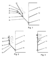
- FIG. 1 shows a side view of a housing wall 10, which is usually designed as the front of the device, where the user accessible control units 28 are located.
- a housing wall 10 which is usually designed as the front of the device, where the user accessible control units 28 are located.
- an opening 14 is provided, which is indicated by dashed lines, and via which the service technician can reach the interior of the device. This opening 14 can be closed with the closure flap 20.
- At least part of an extracorporeal blood treatment module EBM can be provided on the closure flap 20.
- controls and controls 28 such as pumps, especially blood and / or heparin pumps, flow meters, displays, valves, Absperrklemmen, drip chambers, hose holders, sensors (pressure, conductivity, temperature, level -, optical sensors, etc.) and filters arranged.
- sensors pressure, conductivity, temperature, level -, optical sensors, etc.
- filters filters arranged at the back of the control flap are provided the corresponding electric drives of the pumps, supply and disposal hose systems and electronic control and monitoring units.
- the closure flap 20 may be further configured to receive a medical treatment cassette. Accordingly, on the closure flap 20 both holders for mechanical recording and actuators and sensors, or electrical interfaces may be present to interact with appropriate means in the medical treatment cassette.
- the closure flap 20 closes the opening 14, the rear components 29 of the EBM are completely received in the device.
- a pivot point of a second axis of rotation 34 is provided, on which a coupling element 30 engages.
- This coupling element 30 is designed as a coupling rod or a corresponding stamped part or laser-cut part (see Fig. 6 ).
- This coupling element 30 comprises a lower bearing point, which is mounted as the first axis of rotation 12 against the housing.
- the closure flap 20 is therefore pivotable against the housing via the two degrees of freedom of the two axes of rotation 34 and 12.
- the coupling element 30 is preferably designed in the form of two parallel and substantially symmetrical stamped parts, so as to increase the guidance and torsional rigidity.
- the closure flap 20 can be opened after the opening of closure elements, not shown, such as latches or notches about the first axis of rotation 12 and thus passes in the third working position Fig. 1 ,
- closure elements not shown, such as latches or notches about the first axis of rotation 12 and thus passes in the third working position Fig. 1
- the front of the flap 20 is inclined with the controls and controls 28 down and the EBM is outside the housing and is well accessible from above and the sides for service tasks.
- An unillustrated stop between the closure flap 20 and the coupling element 30 ensures that the closure flap 20 does not pivot further down due to gravity.
- an unillustrated stop between the coupling element 30 and the housing ensures that its pivotal movement is limited.
- a tether 17 may preferably be secured between the housing and the closure flap 20 and in the deployed position (see eg Fig. 1 ) absorb at least part of the weight forces.
- the first, second and third positions are each stable positions. That is, it must overcome a resistance in the form of a catch, or open a bolt or a movement against gravity are performed to bring the flap from this stable position.
- Fig. 1-5 Schematic diagrams are.
- the second axis of rotation 34 need not be arranged below the closure flap 20, but the closure flap may also extend below the second axis of rotation 34, as shown by the extension 37 of the closure flap 20 down in Fig. 2 is shown.
- the axes of rotation 12, 34 may be offset inwardly, so that the corresponding bearings in the closed position according to Fig. 3 completely housed in the housing and not visible from the outside. This is, for example, at the bearing point of the first axis of rotation 12 according to Fig. 6 shown.
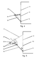
- Fig. 5 an advantage of the invention over the prior art can be seen.
- Embodiments with a first axis of rotation 12 and without a second axis of rotation 34 were known from the prior art Fig. 5 can be greater than the opening angle ⁇ through the second axis of rotation 34 of the opening angle ⁇ , so that the service person can reach well from above the back of the EBM. This has not been possible so far, because due to the limitations of the cable and hose lengths, the EBM could not be folded forward over a larger lower opening angle ⁇ . Due to the two axes of rotation, a larger opening angle ⁇ can be achieved without the EBM being far away from the housing.
- Fig. 2 The execution according to Fig. 2 , in which the shutter 20 is vertically aligned is just one example. Likewise, other service orientations, for example. Vertically +/- 10 ° or +/- 30 ° be advantageous or the alternative embodiment of Fig. 4 in which the closure flap 20 faces upwards with its front side. Thus, in the latter case, a service person can reach the inside of the device well through the opening 14 and at the same time reach, read and operate the operating and control elements 28 of the closure flap 20.
- Fig. 7 shows a variant in which the side wall 10 is inclined in the region of the opening 14 upwards.
- a rounding is provided as a convex contour.
- the device is given an appealing design, and since the closure flap 20 lies approximately at the level of the breast of a person standing in front of it, operating devices located on the closure flap 20 are easier to reach.
- the angular position of the closure flap 20, as in Fig. 7 shown identical to the orientation of the closed state. So a parallel offset was performed.
- a safety belt 17 is shown, which is held on the one hand on the housing wall 10 or in the housing and attached to the other on the closure flap 20.
- This safety belt 17 is designed as a limp element, such as rope, belt or belt and stands according to Fig. 5 under tension, so absorbs weight forces of the shutter 20 and the EBM 29 and provides for the limitation of the opening angle ⁇ . Also, the opening angle ⁇ can be limited by the gripping belt 17.
- Fig. 6 shows a specific embodiment of the coupling element 30, of which preferably two identical or symmetrical executed and aligned in parallel and cooperatively store the flap 20. According to the principles of Fig. 1-5 it appears as if the coupling element 30 is visible from the outside in the closed first position. This is not absolutely necessary, since the coupling element 30 also according to Fig. 6 can be executed arcuate. Here, a lower leg 30a is always in the housing, while an upper leg 30b can swing out of the housing through the opening 14 for the open working positions. Thus, the visual impression of the exterior view of the device below the closure flap 20 is not disturbed by a visible coupling element 30. Fig. 6 further shows a stop 31, which limits the slot 39 upwards.
- the stopper 31 ensures that at a removal of the EBM a double movement, ie a lifting and a lateral displacement must be performed, so as to accidentally fall out, as in to prevent an abutment from below.
- the coupling element 30 is as a stamped and bent part made of metal with a sufficient thickness, for. Min. 2 mm +/- 1 mm and has on an upper leg 30b an Entriegler 35, and a bend generated by bending 36, which is engageable with a corresponding stop (not shown) on the closure flap 20 and thus the closure flap 20th in a vertical working position according to Fig. 2 can hold.
- the coupling element 30 can easily deform elastically so that the angled portion 36 can be removed from the aforementioned abutment like a bolt and the closure flap 20 can be pivoted in succession along the second axis of rotation 34. In this way, the storage of the closure flap 20 and also the definition of the working positions can be realized in a one-piece coupling element 30 cost-effective, such as by a laser-cut workpiece on the one hand.
- Fig. 8 shows the storage of the coupling element 30 via a bearing support 43 which is fixed to and preferably in the device housing.
- a bearing support 43 which is fixed to and preferably in the device housing.
- plastic discs 42 On both sides of the coupling element 30 are plastic discs 42, to one side in addition a washer 41 is provided.
- a rivet 44 On the other side, a rivet 44 is used, which holds the said elements under axial prestress.
- a braking or a certain damping of the coupling element 30 is achieved in addition to the storage. Since the EBM has a considerable weight of about 15 kg, this braking or damping makes sense, since with undamped mechanism when reaching the end position high forces would be exerted on the construction and there would be the risk of falling out of the EBM.
- the damping can be assisted by gas springs / dampers (not shown).
- the plastic discs 42 facilitate by the resistance to movement, which they exert on the coupling element 30, the insertion of the EBMs during service and assembly activities in the appropriate recordings. Introducing a bearing pin of the EBMs in the corresponding receptacle of the coupling element 30 is namely facilitated by the fact that the coupling element 30 remains stable in position by said braking.
Landscapes
- Health & Medical Sciences (AREA)
- Engineering & Computer Science (AREA)
- Heart & Thoracic Surgery (AREA)
- Urology & Nephrology (AREA)
- Vascular Medicine (AREA)
- Anesthesiology (AREA)
- General Health & Medical Sciences (AREA)
- Veterinary Medicine (AREA)
- Public Health (AREA)
- Animal Behavior & Ethology (AREA)
- Life Sciences & Earth Sciences (AREA)
- Biomedical Technology (AREA)
- Hematology (AREA)
- Mechanical Engineering (AREA)
- Emergency Medicine (AREA)
- Chemical & Material Sciences (AREA)
- Chemical Kinetics & Catalysis (AREA)
- Water Supply & Treatment (AREA)
- Cardiology (AREA)
- External Artificial Organs (AREA)
Description
- Die Erfindung bezieht sich auf ein Gerätegehäuse für medizinische Geräte mit einer Verschlussklappe für Servicezwecke.
- Derartige Gerätegehäuse werden häufig bei Blutbehandlungsgeräten wie bspw. Hämodialysemaschinen eingesetzt. Hämodialyse umfasst auch Hämofiltration und Hämodifiltration.
- Bei diesen Geräten ist es notwendig, im Servicefall einfach an das Innere des Geräts zu gelangen. Dazu wird eine Verschlussklappe, welche über ein Scharnier oder Gelenk an einer Seite oder der Front des Geräts befestigt ist, aus dem Gehäuse ausgeklappt. An dieser Verschlussklappe sind üblicherweise technische Einrichtungen, wie z.B. das extrakorporale Blutbehandlungsmodul (EBM) befestigt. So kann ein Servicetechniker einfach an das Geräteinnere und an alle Seiten des EBM gelangen, da letzteres aufgrund des Aufklappens zumindest großteils außerhalb des Geräteinneren befindlich ist.
- Im Hausgerätebau sind, wie unter
DE 10 2005 021 540 A1 oderEP 1 535 556 B1 gezeigt, auch Scharniere bekannt, welche eine Schwenk- und Schiebebewegung verbinden. Auch lassen sich gemäßWO 2008/010004 A1 über mehrgliedrige Koppelgetriebe komplexe Bewegungen von Klappen oder Deckeln realisieren. - Bei bekannten Bauformen der Verschlussklappe von Blutbehandlungsgeräten wird üblicherweise lediglich eine Schwenkachse vorgesehen. Dabei ist die Front der Verschlussklappe, an der sich diverse Einstell- und Anzeigeeinheiten befinden, im ausgeklappten Zustand nach unten geneigt, so dass sie von dem Servicetechniker schlecht einsehbar ist.
-
US 2009/0107335 A1 betrifft eine Luftfalle für eine medizinische Infusionsvorrichtung. -
US 5,482,440 betrifft ein Blutbehandlungssystem unter Verwendung eines peristaltischen Pumpmoduls mit einem Ventil. -
US 2008/0018131 A1 betrifft ein Schwanenhalsscharnier für ein Kraftfahrzeug. -
US 2002/0147423 A1 betrifft Systeme und Verfahren zum Durchführen einer Blutbehandlung und/oder zum Durchführen von Fluidaustauschverfahren. - Es ist die Aufgabe der Erfindung die bekannten Nachteile zu vermeiden und ein kostengünstiges und robustes Gehäuse bereitzustellen, bei welcher der Techniker die benötigten Serviceaufgaben im Geräteinneren und den an der Verschlussklappe befindlichen Komponenten vornehmen und gleichzeitig die an der Vorderseite der Verschlussklappe befindlichen Bedienkomponenten gut erreichen kann.
- Diese Aufgabe wird durch das Gerätegehäuse mit den Merkmalen des Anspruchs 1 gelöst. Weiterbildende Ausführungsformen sind in den Unteransprüchen angegeben.
- Das erfindungsgemäße Gerätegehäuse eines Blutbehandlungsgeräts weist eine Gehäusewand und eine Verschlussklappe zum Verschließen einer Öffnung der Gehäusewand in einer ersten Position auf. Dabei ist ein Koppelelement über eine erste Drehachse gegen die Gehäusewand drehbar gelagert und die Verschlussklappe ist über eine zweite Drehachse gegen das Koppelelement drehbar gelagert. Dabei ist die Verschlussklappe zumindest in einer definierten zweiten Arbeitsposition einrichtbar, bei der die Öffnung der Gehäusewand nicht verschlossen ist. Vorteilhafterweise ist die Verschlussklappe auch in einer dritten definierten Arbeitsposition einrichtbar, bei der die Öffnung der Gehäusewand nicht verschlossen ist. Die Öffnung ist bspw. eine Serviceöffnung, durch die eine Serviceperson das Innere des Geräts oder an der Rückseite der Verschlussklappe befindliche Komponenten erreichen kann. Die erste und zweite Drehachse sind vorzugsweise parallel und komplanar oder parallel zu der Gehäuseöffnung und/oder der Verschlussklappe ausgerichtet. Ferner ist die erste Drehachse insbesondere nicht kollinear zu der zweiten Drehachse; sie haben also einen seitlichen Versatz. Die Arbeitspositionen werden als je eine definierte Lage der Verschlussklappe verstanden, welche entweder über Haltemittel, wie Rasten, Magnete, Hebel, Riegel, Fanggurte o.ä. oder der Schwerkraft bestimmt werden und bei der die Verschlussklappe aufgrund der genannten Mittel in dieser Lage gehalten wird. Während bei einer bekannten Klappe nur eine Drehachse vorgesehen ist, so kann durch die zusätzliche zweite Drehachse die Winkellage der Verschlussklappe in der Lage, bei der das Koppelelement in einer komplett ausgeklappten Lage ist, verändert und so eingerichtet werden, dass die Serviceperson neben den Servicebereichen auch die Front mit den Bedien- und Steuerelementen gut erreichen. Da diese Arbeitspositionen eine Lagestabilität aufweisen, kann die Serviceperson gut in diesen Lagen an der Verschlussklappe arbeiten, Einstellungen vornehmen und das Geräteinnere erreichen.
- Vorteilhafterweise ist die Öffnung an einer Gehäusewand angebracht, welche im Wesentlichen vertikal ausgerichtet ist. So kann die Verschlussklappe nach unten weggeklappt werden und der Schwerkraft folgend in eine der entsprechenden Arbeitspositionen gebracht werden. Da die Verschlussklappe in der geschlossenen Position die Öffnung verschließt, sind die an der Verschlussklappe angeformten Bedien- und Steuerelemente für den Benutzer in dieser Lage ebenfalls vertikal ausgerichtet und somit gut ablesbar.
- Weiterführend kann die Verschlussklappe über keine weiteren Drehachsen und/oder Koppelelemente gegen das Gerätegehäuse gelagert sein. Diese Formulierung umfasst, dass sowohl an der Verschlussklappe als auch dem Koppelelement keine weiteren zwischengeschalteten Drehachsen vorgesehen sind. Das erfindungsgemäße Koppelelement kann aber mehrteilig sein, wie etwa durch mehrere parallel angeordnete baugleiche oder -ähnliche Teile mit Lagerpunkten die auf den gleichen Drehachsen liegen. Während es in der Mechanik bekannt ist, Komponenten über mehrgliedrige Koppelelemente, wie z.B. viergliedrige Koppelgetriebe, zu führen, wird bei der vorgeschlagenen Konstruktion eine einfache und kostengünstige Lösung bereitgestellt.
- Ferner wird weiterführend auch die Verschlussklappe bei ihrer Bewegung über keine Linearführungen gegen das Gerätegehäuse geführt. Eine Linearführung beinhaltet i.d.R. die Gefahr des Verkantens der Führung, ist mit erhöhten Herstellkosten verbunden und eher gegen Verschleiß anfällig. So ergibt sich vorliegend ein Vorteil der exakten und kostengünstigen Führung. Diese Formulierung umfasst, dass vorzugsweise sowohl an der Verschlussklappe, wie auch dem Koppelelement keine Lagerungen in Form einer Linearführung vorgesehen sind.
- In einer weiteren Ausgestaltung ist ein Rastmechanismus zwischen dem Koppelelement und der Verschlussklappe vorgesehen ist. Vorzugsweise ist, wenn der Rastmechanismus in einer rastenden Stellung ist, die Verschlussklappe in der zweiten Arbeitsposition im Wesentlichen vertikal ausgerichtet. Im Wesentlichen vertikal umfasst insbesondere Winkelabweichungen von +/- 15°, vorzugsweise +/-5° gegen die Vertikale. Durch die vertikale Ausrichtung kann die Serviceperson die Bedien- und Steuerelemente gut ablesen und die Verschlussklappe ist gegen ein Herausschwenken aus dieser Stellung gesichert.
- Der Rastmechanismus kann insbesondere durch manuell verschließ- und/oder öffenbare Riegel oder Verhakungen oder durch federgestützte Rasten oder magnetische oder reibhaftende Mittel oder Ausnutzung der Schwerkraft realisiert sein. Der Rastmechanismus kann auch mehrere rastende Stellungen aufweisen.
- Im Fall, dass die Gehäusewand des Gehäuses leicht schräg, nach oben geneigt zulaufend ausgeführt und/oder entsprechend gewölbt ist, ist es vorteilhaft, die Neigung der Verschlussklappe parallel zu der Gehäusewand auszuführen.
- Vorteilhafterweise tendiert die Verschlussklappe aufgrund der Schwerkraft dazu, von der zweiten Arbeitsposition in die dritte Arbeitsposition zu schwenken. Dabei ist die dritte stabile Arbeitsposition eine Lage, bei der die Öffnung der Gehäusewand geöffnet ist und die Verschlussklappe nicht in der vertikalen Lage ist. An der dritten Arbeitsstation kann alternativ ein oben beschriebener Rastmechanismus vorgesehen sein.
- Vorteilhafterweise kann die Lagerung der Verschlussklappe gegen das Koppelelement einen Längsschlitz aufweisen, über den die Verschlussklappe gegenüber dem Koppelelement (30) lösbar und insbesondere aushebbar ist. Ein derartiger Längsschlitz kann als U-förmige Aufnahme so in das Koppelelement geformt sein, dass eine Achse oder Bolzen der Verschlussklappe aufgrund der Schwerkraft in den Grund des "U"s drängt. Für Service- und Austauschzwecke ist so die Verschlussklappe durch Anheben leicht entfernbar. Selbstverständlich ist eine Funktionsumkehr durch einen wechselseitigen Austausch der Aufnahme und des Bolzens möglich. Ggf. ist dieses Entfernen erst nach Öffnen eines Verschlusselements, wie eines Riegels o.ä. möglich. Auch kann ein Anschlag vorgesehen sein, der ein einfaches Herausrutschen aus der U-förmigen Aufnahme verhindert und die Entnahme nur über eine mehrstufige Bewegung in unterschiedlichen Richtungen erlaubt.
- Zur Verbesserung der Festigkeit und insbesondere Verwindungssteifigkeit können auch zwei oder mehr im Wesentlichen spiegelsymmetrische oder identische Koppelelemente vorgesehen sein, die parallel zueinander ausgerichtet sind. Hierbei sind die Achsen der Lagerungen jeweils kollinear.
- In einer weiterführenden Ausgestaltung kann das Koppelelement bogenförmig sein und ein unterer Schenkel des Bogens verbleibt in allen drei Positionen innerhalb des Gerätegehäuses und ein oberer Schenkel des Bogens wird in den geöffneten Arbeitspositionen durch die Öffnung aus dem Gehäuse geführt. Der Begriff "Bogen" ist hier weit zu verstehen und soll insbesondere jede mechanische Ausgestaltung des Koppelelements umfassen, bei der die Lagerstellen der Drehachsen so miteinander verbunden sind, dass in ihrer Mitte zumindest teilweise eine lichte Weite entsteht, in welche beim Übergang in eine der geöffneten Arbeitspositionen die Gehäusewand teilweise aufgenommen werden kann. Durch diese Ausgestaltung kann das Koppelelement unterhalb der genannten Öffnung komplett innerhalb des Gehäuses geführt werden und so ergibt sich ein optischer, designmäßiger Vorteil.
- Vorteilhafterweise sind an der Außenseite der Verschlussklappe Bedienelemente des Geräts angeordnet. Hierzu zählen elektrische oder mechanische Einstelleinrichtungen, Bedienelemente, Anzeigen oder (Schlauch-)Pumpen, Verschlüsse, Ventile oder ähnliches.
- Ferner kann der Zugangsbereich zu der Öffnung der Gehäusewand in der dritten Arbeitsposition größer sein als in der zweiten Arbeitsposition. Der genannte Zugangsbereich wird als der Raum vor der Öffnung im Abstand von 0 bis 60 cm von der Gehäusewand nach außen definiert. Durch das Wegklappen der Verschlussklappe von der zweiten in die dritte Arbeitsposition um die zweite Drehachse wird dieser Raum größer und somit das Innere des Gehäuses besser für Montageaufgaben erreichbar. Wenn lediglich eine einzige (untere) Drehachse vorhanden wäre, so ließe sich der Zugangsbereich nur dadurch vergrößern, dass der Kippwinkel dieser Drehachse vergrößert würde. Dies bringt aber den Nachteil, dass die Entfernung von der Verschlussklappe zum Gehäuse auch größer würde, was das Problem erzeugt, dass die Anschlusskabel und -schläuche entsprechend größer ausgelegt werden müssten. Durch die definierte dritte Arbeitsposition wird zum einen die Öffnung besser frei gegeben und dies ohne dass der genannte Abstand, also die benötigte Verbindungslänge der Versorgungsleitungen, entsprechend erhöht werden muss.
- Auch kann in der dritten Arbeitsposition der Öffnungswinkel der Verschlussklappe größer sein als der Öffnungswinkel des Koppelelements. Der Öffnungswinkel wird verstanden als die Winkeldifferenz der Drehung des jeweiligen Elements von der ersten Position in die dritte Arbeitsposition. Dieser Winkel ist nicht die Relativbewegung in der Drehachse, sondern wird auf eine ortsfeste Bezugsgröße, wie z.B. die Seitenwand bezogen. Aufgrund dieser Winkellage ist die Rückseite der an der Innenseite der Verschlussklappe befindlichen Anbauteile besser in der ausgeklappten dritten Arbeitsposition von oben für Servicezwecke zugänglich.
- Anhand der Zeichnung wird die Erfindung erläutert. Es zeigen:
- Fig. 1
- eine Prinzipskizze einer Seitenansicht des Gerätegehäuses in der dritten Arbeitsposition, bei der die Verschlussklappe geöffnet ist und die Verschlussklappe nicht vertikal ausgerichtet ist,
- Fig. 2
- die Prinzipskizze in einer zweiten Arbeitsposition, bei der ein Rastmechanismus die Verschlussklappe vertikal oder senkrecht hält,
- Fig. 3
- die Prinzipskizze in einer ersten Position, bei der die Verschlussklappe geschlossen ist,
- Fig. 4
- eine alternative Ausführungsform der zweiten Arbeitsposition,
- Fig. 5
- eine alternative Ausführungsform der dritten Arbeitsposition,
- Fig. 6
- eine konkrete Ausgestaltung des Koppelelements,
- Fig. 7
- eine Variante der
Fig. 2 mit schräger Front der Seitenwand und. - Fig. 8
- die Lagerung der Koppelelemente 30.
- In der Prinzipskizze gemäß
Fig. 1 wird die Erfindung vereinfacht dargestellt. Sie zeigt eine Seitenansicht einer Gehäusewand 10, welche üblicherweise als die Gerätefront ausgeführt ist, an welcher sich dem Benutzer zugängliche Bedienteile 28 befinden. In der Gehäusewand 10 ist eine Öffnung 14 vorgesehen, welche gestrichelt angedeutet ist, und über die der Servicetechniker das Innere des Gerätes erreichen kann. Diese Öffnung 14 kann mit der Verschlussklappe 20 verschlossen werden. - An der Verschlussklappe 20 können zumindest Teiles eines extrakorporalen Blutbehandlungsmoduls EBM vorgesehen sein. Dabei sind an der Vorderseite der Bedienklappe des Blutbehandlungsgeräts Bedien- und Steuerelemente 28, wie Pumpen, insbesondere Blut- und/oder Heparinpumpen, Durchflussmesser, Anzeigen, Ventile, Absperrklemmen, Tropfkammern, Schlauchhalter, Sensoren (Druck-, Leitfähigkeits-, Temperatur-, Pegel-, optische Sensoren etc.) und Filter, angeordnet. An der Rückseite der Bedienklappe sind die entsprechenden elektrischen Antriebe der Pumpen, Ver- und Entsorgungsschlauchsysteme und elektronische Steuer- und Kontrolleinheiten vorgesehen.
- Die Verschlussklappe 20 kann weiter dazu eingerichtet sein, eine medizinische Behandlungskassette aufzunehmen. Entsprechend können an der Verschlussklappe 20 sowohl Halterungen zur mechanischen Aufnahme als auch Aktoren und Sensoren, bzw. elektrische Schnittstellen vorhanden sein, um mit entsprechenden Mitteln in der medizinischen Behandlungskassette zu interagieren.
- Wenn die Verschlussklappe 20 die Öffnung 14 verschließt, werden die rückseitigen Bestandteile 29 des EBM komplett im Gerät aufgenommen. Dies entspricht der üblichen Arbeitsweise des Geräts und ist in
Fig. 3 dargestellt. An einem unteren Bereich der Verschlussklappe 20 ist ein Drehpunkt einer zweiten Drehachse 34 vorgesehen, an dem ein Koppelelement 30 angreift. Dieses Koppelelement 30 ist als eine Koppelstange oder ein entsprechendes Stanzteil oder lasergeschnittenes Teil ausgeführt (sieheFig. 6 ). Dieses Koppelelement 30 umfasst einen unteren Lagerpunkt, welcher als erste Drehachse 12 gegen das Gehäuse gelagert ist. Die Verschlussklappe 20 ist also über die zwei Freiheitsgrade der zwei Drehachsen 34 und 12 gegen das Gehäuse schwenkbar. In einer praktischen Ausführungsform wird vorzugsweise das Koppelelement 30 in Form von zwei parallelen und im Wesentlichen symmetrischen Stanzteilen ausgeführt, um so die Führung und Verwindungssteifigkeit zu erhöhen. - Von der in
Fig. 3 gezeigten ersten geschlossenen Position lässt sich die Verschlussklappe 20 nach dem Öffnen von nicht dargestellten Verschlusselementen, wie Riegeln oder Rasten um die erste Drehachse 12 aufklappen und gelangt so in die dritte Arbeitsposition gemäßFig. 1 . Hier ist die Front der Verschlussklappe 20 mit den Bedien- und Steuerelementen 28 nach unten geneigt und das EBM liegt außerhalb des Gehäuses und ist von oben und den Seiten gut für Serviceaufgaben zugänglich. Ein nicht dargestellter Anschlag zwischen der Verschlussklappe 20 und dem Koppelelement 30 sorgt dafür, dass die Verschlussklappe 20 nicht aufgrund der Schwerkraft weiter nach unten schwenkt. Ebenso sorgt ein nicht dargestellter Anschlag zwischen dem Koppelelement 30 und dem Gehäuse dafür, dass seine Schwenkbewegung begrenzt wird. Ein Halteband oder Fanggurt 17 kann bevorzugt zwischen dem Gehäuse und der Verschlussklappe 20 befestigt sein und in der ausgeklappten Stellung (siehe z.B.Fig. 1 ) zumindest einen Teil der Gewichtskräfte aufnehmen. - Das bislang beschriebene Schwenken ist ein Schwenken ausschließlich um die erste Drehachse 12. Wenn nun die Verschlussklappe 20 entgegen dieser Schwenkrichtung um die zweite Schwenkachse 34 geschwenkt wird, so gelangt die Verschlussklappe 20 in die zweite geöffnete Arbeitsposition gemäß
Fig. 2 , bei der die Verschlussklappe 20 vertikal ausgerichtet ist, das EBM weiterhin gut erreichbar ist und die Bedien- und Steuerelemente 28 vertikal nach vorne ausgerichtet. Anders als in der dritten Arbeitsposition sind die Bedien- und Steuerelemente 28 nicht nach unten geneigt. In dieser zweiten Arbeitsposition kann der Servicetechniker die üblichen Bedienvorgänge des Benutzers gut nachvollziehen und gleichzeitig die notwendigen Serviceaufgaben vornehmen. - Die erste, zweite und dritte Position sind jeweils stabile Lagen. Das heißt, es muss ein Widerstand in Form einer Rast überwunden werden, oder ein Riegel geöffnet oder eine Bewegung entgegen der Schwerkraft durchgeführt werden, um die Verschlussklappe aus dieser stabilen Lage zu bringen.
- Es sei betont, dass die
Fig. 1 - 5 Prinzipskizzen sind. So muss bspw. die zweite Drehachse 34 nicht unterhalb der Verschlussklappe 20 angeordnet sein, sondern die Verschlussklappe kann sich auch unterhalb der zweiten Drehachse 34 erstrecken, wie dies durch die Verlängerung 37 der Verschlussklappe 20 nach unten inFig. 2 dargestellt ist. Ebenfalls können die Drehachsen 12, 34 nach innen versetzt sein, so dass die entsprechenden Lagerungen in der geschlossenen Position gemäßFig. 3 komplett im Gehäuse aufgenommen und von außen nicht sichtbar sind. Dies ist bspw. bei dem Lagerpunkt der ersten Drehachse 12 gemäßFig. 6 gezeigt. - Aus
Fig. 5 ist ein Vorteil der Erfindung gegenüber dem Stand der Technik ersichtlich. Bekannt aus dem Stand der Technik waren Ausführungen mit einer ersten Drehachse 12 und ohne eine zweite Drehachse 34. GemäßFig. 5 kann durch die zweite Drehachse 34 der Öffnungswinkel β größer als der Öffnungswinkel α sein, so dass die Serviceperson gut von oben die Rückseite des EBM erreichen kann. Dies war bislang nicht möglich, da aufgrund der Begrenzungen der Kabel- und Schlauchlängen das EBM nicht über einen größeren unteren Öffnungswinkel α weiter vorgeklappt werden konnte. Durch die beiden Drehachsen kann ein größerer Öffnungswinkel β erreicht werden, ohne dass das EBM weit von dem Gehäuse entfernt ist. - Die Ausführung gemäß
Fig. 2 , bei der die Verschlussklappe 20 senkrecht ausgerichtet ist, ist nur ein Beispiel. Ebenso können andere Serviceausrichtungen bspw. senkrecht +/- 10° oder +/- 30° vorteilhaft sein oder die alternative Ausführung derFig. 4 , bei der die Verschlussklappe 20 mit ihrer Frontseite nach oben zeigt. So kann eine Serviceperson im letzteren Fall gut zum einen durch die Öffnung 14 das Geräteinnere erreichen und gleichzeitig die Bedien- und Steuerelemente 28 der Verschlussklappe 20 erreichen, ablesen und bedienen. -
Fig. 7 zeigt eine Variante, bei der die Seitenwand 10 im Bereich der Öffnung 14 nach oben geneigt ist. Zusätzlich ist eine Rundung als eine konvexe Kontur vorgesehen. Dadurch wird dem Gerät ein ansprechendes Design verliehen und da die Verschlussklappe 20 etwa in Brusthöhe einer vor ihr stehenden Person liegt, sind an der Verschlussklappe 20 befindliche Bedienteile besser zu erreichen. Nach dem Öffnen ist die Winkellage der Verschlussklappe 20, wie inFig. 7 dargestellt, identisch zu der Ausrichtung des geschlossenen Zustands. Es wurde also ein Parallelversatz durchgeführt. - Ferner ist in
Fig. 5 ein Fanggurt 17 dargestellt, welcher zum einen an der Gehäusewand 10 oder im Gehäuse gehalten und zum anderen an der Verschlussklappe 20 befestigt ist. Dieser Fanggurt 17 ist als ein biegeschlaffes Element, wie Seil, Band oder Gurt ausgeführt und steht gemäßFig. 5 unter Zugspannung, nimmt so Gewichtskräfte der Verschlussklappe 20 und des EBM 29 auf und sorgt für die Begrenzung des Öffnungswinkels β. Auch kann durch den Fanggurt 17 der Öffnungswinkel α begrenzt werden. -
Fig. 6 zeigt eine konkrete Ausgestaltung des Koppelelements 30, von dem vorzugsweise zwei Stück baugleich oder symmetrisch ausgeführt und parallel ausgerichtet sind und zusammenwirkend die Verschlussklappe 20 lagern. Gemäß den Prinzipien derFig. 1 - 5 erscheint es, als ob das Koppelelement 30 auch in der geschlossenen ersten Position von außen sichtbar sei. Dies ist aber nicht zwingend nötig, da das Koppelelement 30 auch gemäßFig. 6 bogenförmig ausgeführt sein kann. Hierbei ist ein unterer Schenkel 30a stets im Gehäuse, während ein oberer Schenkel 30b für die geöffneten Arbeitspositionen durch die Öffnung 14 aus dem Gehäuse herausschwenken kann. So wird der optische Eindruck der Außenansicht des Geräts unterhalb der Verschlussklappe 20 nicht durch ein sichtbares Koppelelement 30 gestört.Fig. 6 zeigt ferner einen Anschlag 31, welcher den Schlitz 39 nach oben begrenzt. Wenn der Schlitz 39 zusätzlich zur Lagerung um die Drehachse 34 verwendet wird, so sorgt der Anschlag 31 dafür, dass bei einer Entnahme des EBM eine doppelte Bewegung, also ein Anheben und ein seitliches Versetzen durchgeführt werden muss, um so ein unbeabsichtigtes Herausfallen, wie bei einem Anstoßen von unten zu verhindern. - Das Koppelelement 30 ist als Stanz- und Biegeteil aus Metall mit einer ausreichenden Dicke, z. B. min. 2 mm +/- 1 mm ausgeführt und weist an einem oberen Schenkel 30b einen Entriegler 35 auf, und eine durch Biegen erzeugte Abwinklung 36, welche mit einem entsprechenden Anschlag (nicht dargestellt) an der Verschlussklappe 20 in Eingriff bringbar ist und so die Verschlussklappe 20 in einer vertikalen Arbeitsposition gemäß
Fig. 2 halten kann. Wenn nun die Serviceperson den Entriegler 35 (gemäßFig. 6 in die Zeichenebene) drückt, so kann sich das Koppelelement 30 leicht elastisch verformen, so dass die Abwinklung 36 wie ein Riegel aus dem genannten Anschlag entfernbar wird und die Verschlussklappe 20 in Folge entlang der zweiten Drehachse 34 schwenkbar ist. Auf diese Weise können kostengünstig, wie z.B. durch ein lasergeschnittenes Werkstück, zum einen die Lagerung der Verschlussklappe 20 und auch die Definition der Arbeitspositionen in einem einstückigen Koppelelement 30 realisiert werden. -
Fig. 8 zeigt die Lagerung des Koppelelements 30 über einen Lagerträger 43, der am und vorzugsweise im Gerätegehäuse befestigt ist. Zu beiden Seiten des Koppelelements 30 befinden sich Kunststoffscheiben 42, wobei zu der einen Seite zusätzlich eine Unterlegscheibe 41 vorgesehen ist. Zu der anderen Seite wird eine Niet 44 eingesetzt, welche die genannten Elemente unter axialer Vorspannung hält. Dadurch wird neben der Lagerung eine Bremsung oder eine gewisse Dämpfung des Koppelelements 30 erreicht. Da das EBM mit ca. 15 kg ein nennenswertes Gewicht aufweist, ist diese Bremsung oder Dämpfung sinnvoll, da bei ungedämpfter Mechanik beim Erreichen der Endlage hohe Kräfte auf die Konstruktion ausgeübt würden und auch die Gefahr des Herausfallens des EBMs bestünde. Zusätzlich kann die Dämpfung durch Gasdruckfedern/-dämpfer (nicht dargestellt) unterstützt werden. Weiter erleichtern die Kunststoffscheiben 42 durch den Bewegungswiderstand, welchen sie auf das Koppelelement 30 ausüben, das Einführen des EBMs bei Service- und Montagetätigkeiten in die entsprechenden Aufnahmen. Das Einführen eines Lagerbolzens des EBMs in die entsprechende Aufnahme des Koppelelements 30 wird nämlich dadurch erleichtert, dass das Koppelelement 30 durch die genannte Bremsung lagestabil bleibt. - Merkmale unterschiedlicher Ausführungsformen sind frei miteinander kombinierbar. Insbesondere sind die Lagen und Definitionen der unterschiedlichen Arbeitspositionen frei austauschbar und mehr als die drei genannten stabilen Arbeitspositionen sind vom Erfindungsgedanken umfasst.
Claims (15)
- Gerätegehäuse für ein Blutbehandlungsgerät, mit einer Gehäusewand (10) und einer Verschlussklappe (20), welche eine Öffnung (14) in der Gehäusewand (10) in einer ersten Position verschließt und wobei ein Koppelelement (30) über eine erste Drehachse (12) gegen die Gehäusewand (10) drehbar gelagert ist und die Verschlussklappe (20) über eine zweite Drehachse (34) gegen das Koppelelement (30) drehbar gelagert ist, wobei die Verschlussklappe (20) zumindest in einer definierten zweiten Arbeitsposition einrichtbar ist, bei der die Öffnung (14) der Gehäusewand nicht verschlossen ist,
dadurch gekennzeichnet, dass
die Verschlussklappe (20) zumindest Teile (28, 29) eines extrakorporalen Blutbehandlungsmoduls umfassend mindestens eine Pumpe und/oder einen Durchflussmesser und/oder ein Ventil und/oder eine Absperrklemme aufweist. - Gerätegehäuse gemäß Anspruch 1, dadurch gekennzeichnet, dass die Verschlussklappe (20) ferner in einer definierten dritten Arbeitsposition einrichtbar ist, bei der die Öffnung (14) der Gehäusewand nicht verschlossen ist.
- Gerätegehäuse gemäß Anspruch 1 oder 2, dadurch gekennzeichnet, dass die Gehäusewand (10) im Wesentlichen vertikal ausgerichtet ist.
- Gerätegehäuse gemäß einem der vorangegangenen Ansprüche, dadurch gekennzeichnet, dass die Verschlussklappe über keine weiteren Drehachsen und/oder Koppelelemente gegen das Gerätegehäuse gelagert ist.
- Gerätegehäuse gemäß einem der vorangegangenen Ansprüche, dadurch gekennzeichnet, dass die Verschlussklappe (20) über keine Linearführungen gegen das Gerätegehäuse geführt ist.
- Gerätegehäuse gemäß einem der vorangegangenen Ansprüche, dadurch gekennzeichnet, dass ein Rastmechanismus (22, 32; 36) zwischen dem Koppelelement (30) und der Verschlussklappe (20) vorgesehen ist und insbesondere der Rastmechanismus so eingerichtet ist, dass die Verschlussklappe (20) in der zweiten Arbeitsposition im Wesentlichen vertikal ausgerichtet ist, wenn der Rastmechanismus (22, 32) in einer rastenden Stellung ist.
- Gerätegehäuse gemäß einem der Ansprüche 1 - 4 dadurch gekennzeichnet, dass ein Rastmechanismus (22, 32; 36) zwischen dem Koppelelement (30) und der Verschlussklappe (20) vorgesehen ist und insbesondere der Rastmechanismus so eingerichtet ist, dass die Verschlussklappe (20) in der zweiten Arbeitsposition im Wesentlichen parallel zu der Gehäusewand (10) ausgerichtet ist, wenn der Rastmechanismus (22, 32) in einer rastenden Stellung ist.
- Gerätegehäuse gemäß einem der vorangegangenen Ansprüche, dadurch gekennzeichnet, dass die Verschlussklappe aufgrund der Schwerkraft dazu tendiert, von der zweiten Arbeitsposition in die dritte Arbeitsposition zu schwenken.
- Gerätegehäuse gemäß einem der vorangegangenen Ansprüche, dadurch gekennzeichnet, dass das Koppelelement (30) oder die Verschlussklappe (20) im Bereich der zweiten Drehachse (34) einen Längsschlitz aufweist, über den die Verschlussklappe (20) gegenüber dem Koppelelement (30) lösbar und insbesondere aushebbar ist.
- Gerätegehäuse gemäß einem der vorangegangenen Ansprüche, dadurch gekennzeichnet, dass zwei im Wesentlichen spiegelsymmetrische Koppelelemente (30) vorgesehen sind, die parallel zueinander ausgerichtet sind.
- Gerätegehäuse gemäß einem der vorangegangenen Ansprüche, dadurch gekennzeichnet, dass das Koppelelement (30) bogenförmig ist und ein unterer Schenkel (30a) des Bogens in allen drei Positionen innerhalb des Gerätegehäuses verbleibt und ein oberer Schenkel (30b) des Bogens in den geöffneten Arbeitspositionen durch die Öffnung (14) aus dem Gehäuse geführt wird.
- Gerätegehäuse gemäß einem der vorangegangenen Ansprüche, dadurch gekennzeichnet, dass an der Außenseite der Verschlussklappe (20) Bedien- und Funktionselemente (28) des Geräts angeordnet sind.
- Gerätegehäuse gemäß einem der vorangegangenen Ansprüche, dadurch gekennzeichnet, dass der Zugangsbereich zu der Öffnung (14) durch eine Serviceperson in der dritten Arbeitsposition größer ist als in der zweiten Arbeitsposition.
- Gerätegehäuse gemäß einem der vorangegangenen Ansprüche, dadurch gekennzeichnet, dass in der dritten Arbeitsposition der Öffnungswinkel (β) der Verschlussklappe (20) größer ist als der Öffnungswinkel (α) des Koppelelements (30).
- Gerätegehäuse gemäß einem der vorangegangenen Ansprüche, dadurch gekennzeichnet, dass die Teile eines extrakorporalen Blutbehandlungsmoduls Blut- und/oder Heparinpumpen, Tropfkammern, Schlauchhalter, Sensoren, Druck-, Leitfähigkeits-, Temperatur-, Pegel- und/oder optische Sensoren und/oder Filter aufweisen.
Applications Claiming Priority (2)
| Application Number | Priority Date | Filing Date | Title |
|---|---|---|---|
| DE102009045095.5A DE102009045095C5 (de) | 2009-09-29 | 2009-09-29 | Gehäuse mit Verschlussklappe |
| PCT/EP2010/064448 WO2011039248A1 (de) | 2009-09-29 | 2010-09-29 | Gehäuse mit veschlussklappe |
Publications (3)
| Publication Number | Publication Date |
|---|---|
| EP2482866A1 EP2482866A1 (de) | 2012-08-08 |
| EP2482866B1 true EP2482866B1 (de) | 2015-07-22 |
| EP2482866B2 EP2482866B2 (de) | 2024-09-11 |
Family
ID=43216868
Family Applications (1)
| Application Number | Title | Priority Date | Filing Date |
|---|---|---|---|
| EP10759895.5A Active EP2482866B2 (de) | 2009-09-29 | 2010-09-29 | Gehäuse mit veschlussklappe |
Country Status (7)
| Country | Link |
|---|---|
| US (1) | US9289543B2 (de) |
| EP (1) | EP2482866B2 (de) |
| JP (1) | JP5580898B2 (de) |
| CN (1) | CN102596282B (de) |
| DE (1) | DE102009045095C5 (de) |
| IN (1) | IN2012DN00965A (de) |
| WO (1) | WO2011039248A1 (de) |
Families Citing this family (6)
| Publication number | Priority date | Publication date | Assignee | Title |
|---|---|---|---|---|
| DE102015103937A1 (de) | 2015-03-17 | 2016-09-22 | B. Braun Avitum Ag | Blutbehandlungsgerät mit separatem Türabteil |
| DE102016107721B3 (de) * | 2016-04-26 | 2017-07-13 | B. Braun Avitum Ag | Justierbarer Türbeschlag |
| CN107226276B (zh) * | 2017-07-06 | 2019-06-11 | 北京吾天科技有限公司 | 一种保护盖开合机构 |
| DE102021109406A1 (de) * | 2021-04-14 | 2022-10-20 | Endress+Hauser Conducta Gmbh+Co. Kg | Sensorhalterung für einen Durchflusssensor und Verfahren zur Wartung |
| DE102022111834A1 (de) | 2022-05-11 | 2023-11-16 | Berbel Ablufttechnik Gmbh | Mauerkasten |
| CN116534457B (zh) * | 2023-06-28 | 2023-10-17 | 临沂中联水泥有限公司 | 一种危废输送专用双翻板卸灰阀 |
Citations (10)
| Publication number | Priority date | Publication date | Assignee | Title |
|---|---|---|---|---|
| US5482440A (en) | 1993-12-22 | 1996-01-09 | Baxter Int | Blood processing systems using a peristaltic pump module with valve and sensing station for operating a peristaltic pump tube cassette |
| US20020147423A1 (en) | 1997-02-14 | 2002-10-10 | Nxstage Medical Inc. | Systems and methods for performing blood processing and/or fluid exchange procedures |
| WO2005038628A2 (en) | 2003-10-17 | 2005-04-28 | Audiovox Corporation | Mobile entertainment system |
| EP1535556B1 (de) | 2001-01-12 | 2006-07-19 | Alan L. Backus | Spiess-Einheit für Barbecue Grill |
| DE102005021540A1 (de) | 2005-05-10 | 2006-11-16 | BSH Bosch und Siemens Hausgeräte GmbH | Scharnier zum Schwenkverschieben einer zur Seite hin zu öffnenden Tür |
| WO2008010004A1 (en) | 2006-07-14 | 2008-01-24 | Gambro Lundia Ab | Blood processing apparatus |
| US20080018131A1 (en) | 2006-07-24 | 2008-01-24 | Gm Global Technology Operations, Inc. | Gooseneck Hinge Assembly for Vehicle |
| US20090107335A1 (en) | 2007-02-27 | 2009-04-30 | Deka Products Limited Partnership | Air trap for a medical infusion device |
| US7527343B2 (en) | 2004-07-16 | 2009-05-05 | Lg Electronics Inc. | Refrigerator having basket lift apparatus |
| EP2319551A2 (de) | 2007-10-12 | 2011-05-11 | DEKA Products Limited Partnership | Vorrichtung für Hämodialyse |
Family Cites Families (15)
| Publication number | Priority date | Publication date | Assignee | Title |
|---|---|---|---|---|
| JP4416368B2 (ja) * | 1997-02-14 | 2010-02-17 | ネクステージ メディカル インコーポレイテッド | カートリッジ内に配置された体外流体流パネルを使用する流体処理装置及び方法 |
| DE29909761U1 (de) * | 1999-06-07 | 2000-10-19 | Hauni Maschinenbau AG, 21033 Hamburg | Scharnier |
| DE10152436C1 (de) * | 2001-12-14 | 2003-04-10 | Huwil Werke Gmbh | Scharnier |
| DE10224750A1 (de) * | 2002-06-04 | 2003-12-24 | Fresenius Medical Care De Gmbh | Vorrichtung zur Behandlung einer medizinischen Flüssigkeit |
| ES2306951T3 (es) * | 2004-11-24 | 2008-11-16 | Lifebridge Medizintechnik Ag | Dispositivo para proporcionar un circuito de sangre extracorporal. |
| US7935074B2 (en) * | 2005-02-28 | 2011-05-03 | Fresenius Medical Care Holdings, Inc. | Cassette system for peritoneal dialysis machine |
| DE112007000423B4 (de) * | 2006-02-22 | 2017-05-11 | Lg Electronics Inc. | Geschirrspülmaschine |
| US8393690B2 (en) * | 2007-02-27 | 2013-03-12 | Deka Products Limited Partnership | Enclosure for a portable hemodialysis system |
| US8512553B2 (en) * | 2007-07-05 | 2013-08-20 | Baxter International Inc. | Extracorporeal dialysis ready peritoneal dialysis machine |
| AU2008302149B2 (en) * | 2007-09-19 | 2013-11-28 | Fresenius Medical Care Holdings, Inc. | Dialysis systems and related components |
| EP2246080B1 (de) * | 2007-10-12 | 2016-02-10 | DEKA Products Limited Partnership | Extrakorporaler blutkreislauf |
| US8114276B2 (en) * | 2007-10-24 | 2012-02-14 | Baxter International Inc. | Personal hemodialysis system |
| WO2008090406A2 (en) * | 2007-12-21 | 2008-07-31 | Gambro Lundia Ab | Disposable extracorporeal blood circuit and apparatus for the extracorporeal treatment of blood |
| CA2976872C (en) * | 2008-10-07 | 2021-04-13 | Fresenius Medical Care Holdings, Inc. | Priming system and method for dialysis systems |
| NZ592652A (en) * | 2008-10-30 | 2013-10-25 | Fresenius Med Care Hldg Inc | Modular, portable dialysis system |
-
2009
- 2009-09-29 DE DE102009045095.5A patent/DE102009045095C5/de not_active Expired - Fee Related
-
2010
- 2010-09-29 WO PCT/EP2010/064448 patent/WO2011039248A1/de not_active Ceased
- 2010-09-29 JP JP2012530295A patent/JP5580898B2/ja active Active
- 2010-09-29 CN CN201080041680.1A patent/CN102596282B/zh active Active
- 2010-09-29 EP EP10759895.5A patent/EP2482866B2/de active Active
- 2010-09-29 US US13/498,721 patent/US9289543B2/en active Active
-
2012
- 2012-02-02 IN IN965DEN2012 patent/IN2012DN00965A/en unknown
Patent Citations (10)
| Publication number | Priority date | Publication date | Assignee | Title |
|---|---|---|---|---|
| US5482440A (en) | 1993-12-22 | 1996-01-09 | Baxter Int | Blood processing systems using a peristaltic pump module with valve and sensing station for operating a peristaltic pump tube cassette |
| US20020147423A1 (en) | 1997-02-14 | 2002-10-10 | Nxstage Medical Inc. | Systems and methods for performing blood processing and/or fluid exchange procedures |
| EP1535556B1 (de) | 2001-01-12 | 2006-07-19 | Alan L. Backus | Spiess-Einheit für Barbecue Grill |
| WO2005038628A2 (en) | 2003-10-17 | 2005-04-28 | Audiovox Corporation | Mobile entertainment system |
| US7527343B2 (en) | 2004-07-16 | 2009-05-05 | Lg Electronics Inc. | Refrigerator having basket lift apparatus |
| DE102005021540A1 (de) | 2005-05-10 | 2006-11-16 | BSH Bosch und Siemens Hausgeräte GmbH | Scharnier zum Schwenkverschieben einer zur Seite hin zu öffnenden Tür |
| WO2008010004A1 (en) | 2006-07-14 | 2008-01-24 | Gambro Lundia Ab | Blood processing apparatus |
| US20080018131A1 (en) | 2006-07-24 | 2008-01-24 | Gm Global Technology Operations, Inc. | Gooseneck Hinge Assembly for Vehicle |
| US20090107335A1 (en) | 2007-02-27 | 2009-04-30 | Deka Products Limited Partnership | Air trap for a medical infusion device |
| EP2319551A2 (de) | 2007-10-12 | 2011-05-11 | DEKA Products Limited Partnership | Vorrichtung für Hämodialyse |
Non-Patent Citations (5)
| Title |
|---|
| "Dialysegerät Dialog+", FIRMA B. BRAUN, April 2005 (2005-04-01), pages 2-2 - 2-5, XP055290111 |
| "Fachpflege Nephrologie und Dialyse", München, ISBN: 978-3-437-26252-4, article G. BREUCH, pages: 138,271, XP055289188 |
| "Fresenius Medical Care führt neue Dialsemaschine 5008 ein: verbesserte Lebensqualität für Patienten und effizienter Ressourcenverbrauch", PRESSEMITTEILUNG DER PATENTINHABERIN ZUM DIALYSEGERÄT DES TYPS 5008, XP055290114 |
| G . BREUCH ET AL., DIALYSE FÜR EINSTEIGER, 2007, Mün- chen, ISBN: 978-3-437-27790-0 |
| SERVICE-HANDBUCH DER PATENTINHABERIN ZUM DIALYSEGERÄT DES TYPS 5008 |
Also Published As
| Publication number | Publication date |
|---|---|
| IN2012DN00965A (de) | 2015-04-10 |
| DE102009045095B4 (de) | 2011-05-26 |
| DE102009045095C5 (de) | 2019-04-18 |
| EP2482866B2 (de) | 2024-09-11 |
| EP2482866A1 (de) | 2012-08-08 |
| US9289543B2 (en) | 2016-03-22 |
| JP2013505096A (ja) | 2013-02-14 |
| CN102596282A (zh) | 2012-07-18 |
| US20120181296A1 (en) | 2012-07-19 |
| JP5580898B2 (ja) | 2014-08-27 |
| DE102009045095A1 (de) | 2011-04-07 |
| WO2011039248A1 (de) | 2011-04-07 |
| CN102596282B (zh) | 2015-10-14 |
Similar Documents
| Publication | Publication Date | Title |
|---|---|---|
| DE10342659B4 (de) | Flurförderzeug mit einer seitlichen Rahmenöffnung und einer Tür mit Doppelscharnier | |
| DE10249658B4 (de) | Öffnungs- und Schließmechanismus und den Mechanismus verwendende Öffnungs- und Schließvorrichtung | |
| EP2482866B2 (de) | Gehäuse mit veschlussklappe | |
| DE102012109611A1 (de) | Vorrichtung zur Aufnahme einer Kamera mit vier Gelenken | |
| DE202007006689U1 (de) | Antriebseinrichtung für einen Beschlag | |
| DE102012025626A1 (de) | Vorrichtung zur Aufnahme einer Kamera mit vier Gelenken | |
| EP2677104B1 (de) | Sicherheitsschrank | |
| EP2949846A1 (de) | Vorrichtung zum bewegen einer möbelklappe und möbel | |
| DE102005050222A1 (de) | Gelenkbeschlag für Kraftfahrzeugsitze und mit einer Ronde | |
| DE202012102701U1 (de) | Innenliegendes 180-Grad-Scharnier mit zwangsgeführter Schwenkbewegung | |
| WO2017025186A1 (de) | Peritonealdialysegerät | |
| DE102012111428A1 (de) | Kartuschenhalterung für eine Dialysemaschine | |
| EP3447174A1 (de) | Maschinenverkleidung | |
| AT525030A1 (de) | Möbelantriebssystem für ein bewegbares Möbelteil | |
| DE102007043995B4 (de) | Drape-Schutzglas-Anordnung für Operations-Mikroskope | |
| DE102012111095A1 (de) | Schwenkhebelverschluss mit geringer Einbautiefe | |
| DE102011120090B4 (de) | Hutablage für ein Kraftfahrzeug | |
| EP3018280B1 (de) | Türantrieb | |
| EP3276113B1 (de) | Duschtrennwand mit einer tür mit wenigstens einem türscharnier | |
| DE102006004016B4 (de) | Fahrzeug mit einer in Scharnieren aufgenommenen Frontklappe | |
| EP4314573B1 (de) | Kopplungsvorrichtung | |
| DE102010051936A1 (de) | Kameraanordnung | |
| AT521177B1 (de) | Möbelbeschlag | |
| DE202007017835U1 (de) | Gelenkarm-Markise | |
| DE29602411U1 (de) | Vakuumsauger |
Legal Events
| Date | Code | Title | Description |
|---|---|---|---|
| PUAI | Public reference made under article 153(3) epc to a published international application that has entered the european phase |
Free format text: ORIGINAL CODE: 0009012 |
|
| 17P | Request for examination filed |
Effective date: 20120427 |
|
| AK | Designated contracting states |
Kind code of ref document: A1 Designated state(s): AL AT BE BG CH CY CZ DE DK EE ES FI FR GB GR HR HU IE IS IT LI LT LU LV MC MK MT NL NO PL PT RO SE SI SK SM TR |
|
| DAX | Request for extension of the european patent (deleted) | ||
| 17Q | First examination report despatched |
Effective date: 20130214 |
|
| GRAP | Despatch of communication of intention to grant a patent |
Free format text: ORIGINAL CODE: EPIDOSNIGR1 |
|
| INTG | Intention to grant announced |
Effective date: 20140924 |
|
| GRAP | Despatch of communication of intention to grant a patent |
Free format text: ORIGINAL CODE: EPIDOSNIGR1 |
|
| INTG | Intention to grant announced |
Effective date: 20150223 |
|
| GRAS | Grant fee paid |
Free format text: ORIGINAL CODE: EPIDOSNIGR3 |
|
| GRAA | (expected) grant |
Free format text: ORIGINAL CODE: 0009210 |
|
| AK | Designated contracting states |
Kind code of ref document: B1 Designated state(s): AL AT BE BG CH CY CZ DE DK EE ES FI FR GB GR HR HU IE IS IT LI LT LU LV MC MK MT NL NO PL PT RO SE SI SK SM TR |
|
| REG | Reference to a national code |
Ref country code: GB Ref legal event code: FG4D Free format text: NOT ENGLISH |
|
| REG | Reference to a national code |
Ref country code: CH Ref legal event code: EP |
|
| REG | Reference to a national code |
Ref country code: IE Ref legal event code: FG4D Free format text: LANGUAGE OF EP DOCUMENT: GERMAN |
|
| REG | Reference to a national code |
Ref country code: AT Ref legal event code: REF Ref document number: 737520 Country of ref document: AT Kind code of ref document: T Effective date: 20150815 |
|
| REG | Reference to a national code |
Ref country code: FR Ref legal event code: PLFP Year of fee payment: 6 |
|
| REG | Reference to a national code |
Ref country code: DE Ref legal event code: R096 Ref document number: 502010009893 Country of ref document: DE |
|
| REG | Reference to a national code |
Ref country code: CH Ref legal event code: NV Representative=s name: SCHMAUDER AND PARTNER AG PATENT- UND MARKENANW, CH |
|
| REG | Reference to a national code |
Ref country code: SE Ref legal event code: TRGR |
|
| REG | Reference to a national code |
Ref country code: LT Ref legal event code: MG4D |
|
| REG | Reference to a national code |
Ref country code: NL Ref legal event code: MP Effective date: 20150722 |
|
| PG25 | Lapsed in a contracting state [announced via postgrant information from national office to epo] |
Ref country code: NO Free format text: LAPSE BECAUSE OF FAILURE TO SUBMIT A TRANSLATION OF THE DESCRIPTION OR TO PAY THE FEE WITHIN THE PRESCRIBED TIME-LIMIT Effective date: 20151022 Ref country code: FI Free format text: LAPSE BECAUSE OF FAILURE TO SUBMIT A TRANSLATION OF THE DESCRIPTION OR TO PAY THE FEE WITHIN THE PRESCRIBED TIME-LIMIT Effective date: 20150722 Ref country code: LV Free format text: LAPSE BECAUSE OF FAILURE TO SUBMIT A TRANSLATION OF THE DESCRIPTION OR TO PAY THE FEE WITHIN THE PRESCRIBED TIME-LIMIT Effective date: 20150722 Ref country code: LT Free format text: LAPSE BECAUSE OF FAILURE TO SUBMIT A TRANSLATION OF THE DESCRIPTION OR TO PAY THE FEE WITHIN THE PRESCRIBED TIME-LIMIT Effective date: 20150722 Ref country code: GR Free format text: LAPSE BECAUSE OF FAILURE TO SUBMIT A TRANSLATION OF THE DESCRIPTION OR TO PAY THE FEE WITHIN THE PRESCRIBED TIME-LIMIT Effective date: 20151023 |
|
| PG25 | Lapsed in a contracting state [announced via postgrant information from national office to epo] |
Ref country code: PT Free format text: LAPSE BECAUSE OF FAILURE TO SUBMIT A TRANSLATION OF THE DESCRIPTION OR TO PAY THE FEE WITHIN THE PRESCRIBED TIME-LIMIT Effective date: 20151123 Ref country code: HR Free format text: LAPSE BECAUSE OF FAILURE TO SUBMIT A TRANSLATION OF THE DESCRIPTION OR TO PAY THE FEE WITHIN THE PRESCRIBED TIME-LIMIT Effective date: 20150722 Ref country code: ES Free format text: LAPSE BECAUSE OF FAILURE TO SUBMIT A TRANSLATION OF THE DESCRIPTION OR TO PAY THE FEE WITHIN THE PRESCRIBED TIME-LIMIT Effective date: 20150722 Ref country code: IS Free format text: LAPSE BECAUSE OF FAILURE TO SUBMIT A TRANSLATION OF THE DESCRIPTION OR TO PAY THE FEE WITHIN THE PRESCRIBED TIME-LIMIT Effective date: 20151122 Ref country code: PL Free format text: LAPSE BECAUSE OF FAILURE TO SUBMIT A TRANSLATION OF THE DESCRIPTION OR TO PAY THE FEE WITHIN THE PRESCRIBED TIME-LIMIT Effective date: 20150722 |
|
| REG | Reference to a national code |
Ref country code: DE Ref legal event code: R026 Ref document number: 502010009893 Country of ref document: DE |
|
| PG25 | Lapsed in a contracting state [announced via postgrant information from national office to epo] |
Ref country code: DK Free format text: LAPSE BECAUSE OF FAILURE TO SUBMIT A TRANSLATION OF THE DESCRIPTION OR TO PAY THE FEE WITHIN THE PRESCRIBED TIME-LIMIT Effective date: 20150722 Ref country code: EE Free format text: LAPSE BECAUSE OF FAILURE TO SUBMIT A TRANSLATION OF THE DESCRIPTION OR TO PAY THE FEE WITHIN THE PRESCRIBED TIME-LIMIT Effective date: 20150722 Ref country code: SK Free format text: LAPSE BECAUSE OF FAILURE TO SUBMIT A TRANSLATION OF THE DESCRIPTION OR TO PAY THE FEE WITHIN THE PRESCRIBED TIME-LIMIT Effective date: 20150722 Ref country code: CZ Free format text: LAPSE BECAUSE OF FAILURE TO SUBMIT A TRANSLATION OF THE DESCRIPTION OR TO PAY THE FEE WITHIN THE PRESCRIBED TIME-LIMIT Effective date: 20150722 Ref country code: MC Free format text: LAPSE BECAUSE OF FAILURE TO SUBMIT A TRANSLATION OF THE DESCRIPTION OR TO PAY THE FEE WITHIN THE PRESCRIBED TIME-LIMIT Effective date: 20150722 Ref country code: LU Free format text: LAPSE BECAUSE OF FAILURE TO SUBMIT A TRANSLATION OF THE DESCRIPTION OR TO PAY THE FEE WITHIN THE PRESCRIBED TIME-LIMIT Effective date: 20150929 |
|
| PLBI | Opposition filed |
Free format text: ORIGINAL CODE: 0009260 |
|
| PLAF | Information modified related to communication of a notice of opposition and request to file observations + time limit |
Free format text: ORIGINAL CODE: EPIDOSCOBS2 |
|
| PLAX | Notice of opposition and request to file observation + time limit sent |
Free format text: ORIGINAL CODE: EPIDOSNOBS2 |
|
| PG25 | Lapsed in a contracting state [announced via postgrant information from national office to epo] |
Ref country code: RO Free format text: LAPSE BECAUSE OF FAILURE TO SUBMIT A TRANSLATION OF THE DESCRIPTION OR TO PAY THE FEE WITHIN THE PRESCRIBED TIME-LIMIT Effective date: 20150722 |
|
| 26 | Opposition filed |
Opponent name: B. BRAUN AVITUM AG Effective date: 20160422 |
|
| REG | Reference to a national code |
Ref country code: IE Ref legal event code: MM4A |
|
| PG25 | Lapsed in a contracting state [announced via postgrant information from national office to epo] |
Ref country code: IE Free format text: LAPSE BECAUSE OF NON-PAYMENT OF DUE FEES Effective date: 20150929 |
|
| REG | Reference to a national code |
Ref country code: FR Ref legal event code: PLFP Year of fee payment: 7 |
|
| PG25 | Lapsed in a contracting state [announced via postgrant information from national office to epo] |
Ref country code: SI Free format text: LAPSE BECAUSE OF FAILURE TO SUBMIT A TRANSLATION OF THE DESCRIPTION OR TO PAY THE FEE WITHIN THE PRESCRIBED TIME-LIMIT Effective date: 20150722 |
|
| PLBB | Reply of patent proprietor to notice(s) of opposition received |
Free format text: ORIGINAL CODE: EPIDOSNOBS3 |
|
| REG | Reference to a national code |
Ref country code: AT Ref legal event code: MM01 Ref document number: 737520 Country of ref document: AT Kind code of ref document: T Effective date: 20150929 |
|
| PG25 | Lapsed in a contracting state [announced via postgrant information from national office to epo] |
Ref country code: AT Free format text: LAPSE BECAUSE OF NON-PAYMENT OF DUE FEES Effective date: 20150929 |
|
| PG25 | Lapsed in a contracting state [announced via postgrant information from national office to epo] |
Ref country code: MT Free format text: LAPSE BECAUSE OF FAILURE TO SUBMIT A TRANSLATION OF THE DESCRIPTION OR TO PAY THE FEE WITHIN THE PRESCRIBED TIME-LIMIT Effective date: 20150722 |
|
| PG25 | Lapsed in a contracting state [announced via postgrant information from national office to epo] |
Ref country code: BG Free format text: LAPSE BECAUSE OF FAILURE TO SUBMIT A TRANSLATION OF THE DESCRIPTION OR TO PAY THE FEE WITHIN THE PRESCRIBED TIME-LIMIT Effective date: 20150722 Ref country code: HU Free format text: LAPSE BECAUSE OF FAILURE TO SUBMIT A TRANSLATION OF THE DESCRIPTION OR TO PAY THE FEE WITHIN THE PRESCRIBED TIME-LIMIT; INVALID AB INITIO Effective date: 20100929 Ref country code: SM Free format text: LAPSE BECAUSE OF FAILURE TO SUBMIT A TRANSLATION OF THE DESCRIPTION OR TO PAY THE FEE WITHIN THE PRESCRIBED TIME-LIMIT Effective date: 20150722 |
|
| PG25 | Lapsed in a contracting state [announced via postgrant information from national office to epo] |
Ref country code: NL Free format text: LAPSE BECAUSE OF FAILURE TO SUBMIT A TRANSLATION OF THE DESCRIPTION OR TO PAY THE FEE WITHIN THE PRESCRIBED TIME-LIMIT Effective date: 20150722 Ref country code: CY Free format text: LAPSE BECAUSE OF FAILURE TO SUBMIT A TRANSLATION OF THE DESCRIPTION OR TO PAY THE FEE WITHIN THE PRESCRIBED TIME-LIMIT Effective date: 20150722 |
|
| PG25 | Lapsed in a contracting state [announced via postgrant information from national office to epo] |
Ref country code: BE Free format text: LAPSE BECAUSE OF NON-PAYMENT OF DUE FEES Effective date: 20150930 |
|
| REG | Reference to a national code |
Ref country code: FR Ref legal event code: PLFP Year of fee payment: 8 |
|
| PG25 | Lapsed in a contracting state [announced via postgrant information from national office to epo] |
Ref country code: TR Free format text: LAPSE BECAUSE OF FAILURE TO SUBMIT A TRANSLATION OF THE DESCRIPTION OR TO PAY THE FEE WITHIN THE PRESCRIBED TIME-LIMIT Effective date: 20150722 |
|
| PLCK | Communication despatched that opposition was rejected |
Free format text: ORIGINAL CODE: EPIDOSNREJ1 |
|
| STAA | Information on the status of an ep patent application or granted ep patent |
Free format text: STATUS: THE PATENT HAS BEEN GRANTED |
|
| APBM | Appeal reference recorded |
Free format text: ORIGINAL CODE: EPIDOSNREFNO |
|
| APBP | Date of receipt of notice of appeal recorded |
Free format text: ORIGINAL CODE: EPIDOSNNOA2O |
|
| APAH | Appeal reference modified |
Free format text: ORIGINAL CODE: EPIDOSCREFNO |
|
| APBQ | Date of receipt of statement of grounds of appeal recorded |
Free format text: ORIGINAL CODE: EPIDOSNNOA3O |
|
| PG25 | Lapsed in a contracting state [announced via postgrant information from national office to epo] |
Ref country code: MK Free format text: LAPSE BECAUSE OF FAILURE TO SUBMIT A TRANSLATION OF THE DESCRIPTION OR TO PAY THE FEE WITHIN THE PRESCRIBED TIME-LIMIT Effective date: 20150722 |
|
| REG | Reference to a national code |
Ref country code: FR Ref legal event code: PLFP Year of fee payment: 9 |
|
| PG25 | Lapsed in a contracting state [announced via postgrant information from national office to epo] |
Ref country code: AL Free format text: LAPSE BECAUSE OF FAILURE TO SUBMIT A TRANSLATION OF THE DESCRIPTION OR TO PAY THE FEE WITHIN THE PRESCRIBED TIME-LIMIT Effective date: 20150722 |
|
| PGFP | Annual fee paid to national office [announced via postgrant information from national office to epo] |
Ref country code: SE Payment date: 20200826 Year of fee payment: 11 |
|
| REG | Reference to a national code |
Ref country code: SE Ref legal event code: EUG |
|
| PG25 | Lapsed in a contracting state [announced via postgrant information from national office to epo] |
Ref country code: SE Free format text: LAPSE BECAUSE OF NON-PAYMENT OF DUE FEES Effective date: 20210930 |
|
| APBU | Appeal procedure closed |
Free format text: ORIGINAL CODE: EPIDOSNNOA9O |
|
| PLAY | Examination report in opposition despatched + time limit |
Free format text: ORIGINAL CODE: EPIDOSNORE2 |
|
| PLBC | Reply to examination report in opposition received |
Free format text: ORIGINAL CODE: EPIDOSNORE3 |
|
| PLAY | Examination report in opposition despatched + time limit |
Free format text: ORIGINAL CODE: EPIDOSNORE2 |
|
| PLBC | Reply to examination report in opposition received |
Free format text: ORIGINAL CODE: EPIDOSNORE3 |
|
| PUAH | Patent maintained in amended form |
Free format text: ORIGINAL CODE: 0009272 |
|
| STAA | Information on the status of an ep patent application or granted ep patent |
Free format text: STATUS: PATENT MAINTAINED AS AMENDED |
|
| 27A | Patent maintained in amended form |
Effective date: 20240911 |
|
| AK | Designated contracting states |
Kind code of ref document: B2 Designated state(s): AL AT BE BG CH CY CZ DE DK EE ES FI FR GB GR HR HU IE IS IT LI LT LU LV MC MK MT NL NO PL PT RO SE SI SK SM TR |
|
| REG | Reference to a national code |
Ref country code: DE Ref legal event code: R102 Ref document number: 502010009893 Country of ref document: DE |
|
| REG | Reference to a national code |
Ref country code: DE Ref legal event code: R082 Ref document number: 502010009893 Country of ref document: DE Representative=s name: MAUCHER JENKINS PATENTANWAELTE & RECHTSANWAELT, DE |
|
| REG | Reference to a national code |
Ref country code: CH Ref legal event code: U11 Free format text: ST27 STATUS EVENT CODE: U-0-0-U10-U11 (AS PROVIDED BY THE NATIONAL OFFICE) Effective date: 20251001 |
|
| PGFP | Annual fee paid to national office [announced via postgrant information from national office to epo] |
Ref country code: DE Payment date: 20250820 Year of fee payment: 16 |
|
| PGFP | Annual fee paid to national office [announced via postgrant information from national office to epo] |
Ref country code: IT Payment date: 20250820 Year of fee payment: 16 |
|
| PGFP | Annual fee paid to national office [announced via postgrant information from national office to epo] |
Ref country code: GB Payment date: 20250822 Year of fee payment: 16 |
|
| PGFP | Annual fee paid to national office [announced via postgrant information from national office to epo] |
Ref country code: FR Payment date: 20250820 Year of fee payment: 16 |
|
| PGFP | Annual fee paid to national office [announced via postgrant information from national office to epo] |
Ref country code: CH Payment date: 20251001 Year of fee payment: 16 |