EP2482109B1 - Traction limiting element for a fibre optic connection, patch cable and pigtail with this traction limiting element - Google Patents
Traction limiting element for a fibre optic connection, patch cable and pigtail with this traction limiting element Download PDFInfo
- Publication number
- EP2482109B1 EP2482109B1 EP12150005.2A EP12150005A EP2482109B1 EP 2482109 B1 EP2482109 B1 EP 2482109B1 EP 12150005 A EP12150005 A EP 12150005A EP 2482109 B1 EP2482109 B1 EP 2482109B1
- Authority
- EP
- European Patent Office
- Prior art keywords
- limiting element
- receiving
- tension limiting
- receiving device
- fibre
- Prior art date
- Legal status (The legal status is an assumption and is not a legal conclusion. Google has not performed a legal analysis and makes no representation as to the accuracy of the status listed.)
- Active
Links
- 239000000835 fiber Substances 0.000 title claims description 48
- 210000002105 tongue Anatomy 0.000 claims description 39
- 230000003287 optical effect Effects 0.000 claims description 13
- 239000013307 optical fiber Substances 0.000 claims description 10
- 239000004952 Polyamide Substances 0.000 claims description 4
- 239000004697 Polyetherimide Substances 0.000 claims description 4
- 229920002647 polyamide Polymers 0.000 claims description 4
- 229920001601 polyetherimide Polymers 0.000 claims description 4
- 239000002184 metal Substances 0.000 claims description 3
- 239000004033 plastic Substances 0.000 claims description 3
- 229920003023 plastic Polymers 0.000 claims description 3
- 229910000639 Spring steel Inorganic materials 0.000 claims description 2
- 238000005452 bending Methods 0.000 claims description 2
- 239000013013 elastic material Substances 0.000 claims description 2
- 238000009434 installation Methods 0.000 description 6
- 230000006378 damage Effects 0.000 description 5
- 239000000463 material Substances 0.000 description 5
- 238000000926 separation method Methods 0.000 description 5
- 230000005540 biological transmission Effects 0.000 description 3
- 208000027418 Wounds and injury Diseases 0.000 description 2
- 238000002788 crimping Methods 0.000 description 2
- 230000001419 dependent effect Effects 0.000 description 2
- 208000014674 injury Diseases 0.000 description 2
- 230000008439 repair process Effects 0.000 description 2
- 102100029272 5-demethoxyubiquinone hydroxylase, mitochondrial Human genes 0.000 description 1
- 101000770593 Homo sapiens 5-demethoxyubiquinone hydroxylase, mitochondrial Proteins 0.000 description 1
- 238000004026 adhesive bonding Methods 0.000 description 1
- 239000004760 aramid Substances 0.000 description 1
- 229920006231 aramid fiber Polymers 0.000 description 1
- 230000006866 deterioration Effects 0.000 description 1
- 238000006073 displacement reaction Methods 0.000 description 1
- 239000003365 glass fiber Substances 0.000 description 1
- 239000006223 plastic coating Substances 0.000 description 1
- 230000001681 protective effect Effects 0.000 description 1
- 238000010008 shearing Methods 0.000 description 1
- 230000001960 triggered effect Effects 0.000 description 1
Images


Classifications
-
- G—PHYSICS
- G02—OPTICS
- G02B—OPTICAL ELEMENTS, SYSTEMS OR APPARATUS
- G02B6/00—Light guides; Structural details of arrangements comprising light guides and other optical elements, e.g. couplings
- G02B6/46—Processes or apparatus adapted for installing or repairing optical fibres or optical cables
- G02B6/50—Underground or underwater installation; Installation through tubing, conduits or ducts
- G02B6/54—Underground or underwater installation; Installation through tubing, conduits or ducts using mechanical means, e.g. pulling or pushing devices
-
- G—PHYSICS
- G02—OPTICS
- G02B—OPTICAL ELEMENTS, SYSTEMS OR APPARATUS
- G02B6/00—Light guides; Structural details of arrangements comprising light guides and other optical elements, e.g. couplings
- G02B6/24—Coupling light guides
- G02B6/36—Mechanical coupling means
- G02B6/38—Mechanical coupling means having fibre to fibre mating means
- G02B6/3807—Dismountable connectors, i.e. comprising plugs
- G02B6/3887—Anchoring optical cables to connector housings, e.g. strain relief features
- G02B6/38875—Protection from bending or twisting
-
- G—PHYSICS
- G02—OPTICS
- G02B—OPTICAL ELEMENTS, SYSTEMS OR APPARATUS
- G02B6/00—Light guides; Structural details of arrangements comprising light guides and other optical elements, e.g. couplings
- G02B6/24—Coupling light guides
- G02B6/36—Mechanical coupling means
- G02B6/38—Mechanical coupling means having fibre to fibre mating means
- G02B6/3807—Dismountable connectors, i.e. comprising plugs
- G02B6/3887—Anchoring optical cables to connector housings, e.g. strain relief features
- G02B6/3888—Protection from over-extension or over-compression
-
- G—PHYSICS
- G02—OPTICS
- G02B—OPTICAL ELEMENTS, SYSTEMS OR APPARATUS
- G02B6/00—Light guides; Structural details of arrangements comprising light guides and other optical elements, e.g. couplings
- G02B6/24—Coupling light guides
- G02B6/36—Mechanical coupling means
- G02B6/38—Mechanical coupling means having fibre to fibre mating means
- G02B6/3807—Dismountable connectors, i.e. comprising plugs
- G02B6/389—Dismountable connectors, i.e. comprising plugs characterised by the method of fastening connecting plugs and sockets, e.g. screw- or nut-lock, snap-in, bayonet type
- G02B6/3893—Push-pull type, e.g. snap-in, push-on
-
- G—PHYSICS
- G02—OPTICS
- G02B—OPTICAL ELEMENTS, SYSTEMS OR APPARATUS
- G02B6/00—Light guides; Structural details of arrangements comprising light guides and other optical elements, e.g. couplings
- G02B6/46—Processes or apparatus adapted for installing or repairing optical fibres or optical cables
- G02B6/50—Underground or underwater installation; Installation through tubing, conduits or ducts
- G02B6/54—Underground or underwater installation; Installation through tubing, conduits or ducts using mechanical means, e.g. pulling or pushing devices
- G02B6/545—Pulling eyes
-
- G—PHYSICS
- G02—OPTICS
- G02B—OPTICAL ELEMENTS, SYSTEMS OR APPARATUS
- G02B6/00—Light guides; Structural details of arrangements comprising light guides and other optical elements, e.g. couplings
- G02B6/24—Coupling light guides
- G02B6/36—Mechanical coupling means
- G02B6/38—Mechanical coupling means having fibre to fibre mating means
- G02B6/3807—Dismountable connectors, i.e. comprising plugs
- G02B6/389—Dismountable connectors, i.e. comprising plugs characterised by the method of fastening connecting plugs and sockets, e.g. screw- or nut-lock, snap-in, bayonet type
- G02B6/3894—Screw-lock type
Definitions
- the present invention relates to a tension limiting element for a fiber optic connection, as well as a patch cord and a pigtail with a tension limiting element.
- Fiber optic connectors in particular plug connectors, are known from the prior art. These connectors allow you to easily create a fiber optic connection that can even be created by a layperson. Due to the ever-increasing amount of data required even in private households, in many places the fiber optic network is already being installed into the house or apartment so that a broadband connection is available. Even end devices are already connected directly to the fiber optic network. Conventional fiber-optic connectors usually have a positive lock so that the fiber-optic connection cannot be accidentally separated. If such connectors are now also used in home applications, there is, on the one hand, a considerable risk of injury, since such fiber-optic connections can act as tripping hazards and the connection will not be separated if there is excessive tensile load on the connector.
- JP60205511A and JP60205512A reveal a fiber optic connector.
- One half of the connector points to the side Locking arms which engage in corresponding grooves on the counterpart.
- EP 0 510 240 A1 _ reveals a fiber-optic connector that can be protected from unwanted separation with a safety nut.
- a similar fiber optic connector is also available US6152608 shown.
- a tension-limiting element for a fiber-optic connecting line, as well as a patch cord and a pigtail with a tension-limiting element are to be provided, which separates the fiber-optic connection when a maximum permissible tensile force is exceeded.
- a tension limiting element according to the invention for a fiber-optic connection contains at least a first and a second receiving device, as well as means which allow the fiber-optic connection to be separated at a predefined location.
- Both receiving devices have a receiving body.
- This receiving body comprises a receptacle for receiving and fixing one or more optical fibers parallel to an axial direction and connecting means for connecting the first to the second receiving device.
- the connecting means are designed in such a way that the connection between the first and second receiving devices can be separated under the influence of a predetermined or predeterminable tensile force. It is particularly conceivable that the tensile force is individually set or adjustable within predetermined limits.
- the tensile force can be set or adjustable between 5 and 30 N, preferably between 10 and 25 N, particularly preferably between 15 and 20 N.
- the receiving body of one receiving device has a collet with slots and several tongues and the connecting means are arranged on the tongue of the collet.
- a collet is understood to mean any means that encloses a counterpart and is slotted in such a way that its inner diameter can be changed at least in a partial area.
- the fiber arranged in the tension limiter is optimally protected from external influences by the collet.
- a collet chuck makes it possible to easily connect the two holding devices.
- the connecting means can be locking means. This enables easy installation of the draft limiter.
- the connecting means can also have alternative forms, such as a magnetic connection or a material connection with predetermined breaking points.
- At least one connecting means of the receiving body of the first receiving device can have a locking lug.
- This locking lug preferably projects from an outer surface of the receiving body and is at least partially circumferential.
- at least one connecting means of the receiving body of the second receiving device can have a locking edge which can be locked with the locking lug of the first receiving device.
- the locking lug or the locking edge can also be arranged on the receiving body of the other receiving device.
- a combination of locking lug and locking edge for example, a hemispherical projecting structure and a corresponding recess in the opposite receiving body are conceivable.
- both receiving bodies each have a combination of locking lug and locking edge.
- the locking lug and locking edge are then arranged offset on each receiving body.
- the locking lug and the locking edge of the two receiving bodies are aligned with one another so that a locking connection can be created.
- the locking lug and/or the locking edge can be designed in a ramp shape.
- the unlocking force of the connecting means and thus also the maximum tensile force that can be absorbed by the tension limiting element can be influenced by the angle of inclination of the ramp. This angle of inclination is preferably between 45° and 60°. Of course, this unlocking force can also be controlled by other means such as the dimensioning of the tongue or the material used.
- the tongue can consist of an elastic material, preferably plastic, particularly preferably polyamide (PA) or polyetherimide (PEI). Other materials are also conceivable.
- PA polyamide
- PEI polyetherimide
- the tensile force required for separating the optical connection can be adjusted through a suitable choice of material combined with the structural design, in particular the thickness and length of the tongue.
- a securing element is arranged above the tongue so as to be rotatable about an axis of rotation running in the axial direction, so that the clamping force of the tongue can then be influenced depending on the orientation.
- a sleeve-shaped securing element would then have a recess which is arranged corresponding to the tongue. The clamping force of the tongue would then be influenced according to the rotational position of the recess.
- the securing element can be rotated into an open position in which no influence is exerted on the clamping force of the tongue. Such a position is particularly advantageous for assembling the tension limiter because the connecting means then exert the least force during assembly. Accordingly, the securing element can be rotated into a closed position, where any movement of the tongue is blocked. In such a closed position, the securing element completely covers the tongue. Of course, the securing element can assume any position between the open position and the closed position, so that the tensile force can be adjusted continuously.
- the receiving bodies can have a fastening area, in particular a crimp neck, for fastening a strain relief of a fiber optic cable.
- a fastening area ensures that a tensile stress acting on the tension limiter, which is smaller than the tensile force required for separation, does not act on the fiber and possibly cause a deterioration in the transmission quality or even damage the fiber.
- the strain limiter is not equipped with a fiber-optic cable with strain relief, but only with a fiber that has a simple plastic coating.
- Each receptacle for receiving and fixing one or more optical fibers can include at least one conventional ferrule.
- these ferrules can be the means for separating the fiber-optic connection.
- a conventional Ferrule is, for example, a connector pin with at least one hole for receiving an optical fiber.
- Ferrules with an outer diameter of 2.5mm and 1.25mm for glass fibers are particularly well known.
- a ferrule is also understood to mean, for example, an MT ferrule, which can in particular accommodate two or more fibers.
- a ferrule can also have a different shape and/or in particular be designed for plastic fibers.
- the ferrule of the receptacle of the first receptacle can be firmly connected to the receptacle body.
- the end faces of the ferrules must meet each other with a precisely defined pressure in order to enable suitable transmission quality.
- the ferrule of the receptacle of the second receptacle can be resiliently connected to the receptacle body in the axial direction. It goes without saying that the spring-loaded or firmly connected ferrule can be swapped here. It is also conceivable that both ferrules are resiliently connected to the corresponding receiving body.
- the ferrules can be placed on one another using one or more guide sleeves be aligned.
- guide sleeves are known to those skilled in the art, particularly for ferrules with a diameter of 2.5mm or 1.25mm, as slotted sleeves, so-called sleeves.
- the guide sleeve can be attached to the receiving body of the fixed ferrule.
- the first receiving device can comprise a means which, when the first receiving device is separated from the second receiving device, cuts through an optical fiber arranged in the tension limiting element. It is not relevant whether this means is arranged in the first or the second receiving device.
- the receiving body can be designed directly in such a way that it serves as a receptacle for the fibers. Such a solution can be implemented independently of the collet chuck solution mentioned above.
- the means for separating the optical fiber may be a blade which is movable transversely to the axial direction.
- the blade can be a bent sheet metal part, preferably made of spring steel.
- other means are also conceivable. For example, shearing forces could act on the fiber, causing the fiber to break. However, the fiber could also be scratched and put under tension, which would also lead to fiber breakage.
- the blade can be arranged on the receiving body of the first receiving device and the second receiving device can have a ramp.
- This ramp could be designed in such a way that when the two receiving devices are separated, the ramp can be brought into operative connection with the blade in such a way that the blade is displaced and a fiber arranged in the tension limiting element can be severed. It goes without saying that the blade and ramp are interchangeable.
- the receiving body of a receiving device can be replaced by a pull-in head, the pull-in head having a fastening element for attaching a pull-in strand.
- a tension limiting element modified in this way no longer serves to separate a fiber-optic connecting line, it can, for example, serve as a protective device if a pre-assembled optical fiber is to be pulled into a cable duct or into an installation pipe.
- the fastening means on the pull-in head can be designed, for example, as a bore or opening transverse to the axial direction.
- a patch cord according to the invention comprises a fiber-optic cable with fiber-optic connectors arranged on both sides, and between the two connectors a tension-limiting element as described above and defined in claim 1.
- a pigtail according to the invention comprises a fiber-optic cable with a fiber-optic connector arranged on one side and a tension limiting element mounted on the fiber-optic cable, preferably close to the fiber-optic connector, as described above and defined in claim 1.
- close is understood to mean a range from 0mm to 1000mm, preferably 50mm to 500mm, particularly preferably 100mm to 250mm.
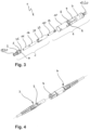
- Figure 1 shows a tension limiting element 1 not according to the invention assembled on a fiber-optic cable 33, with a securing element 10 in a closed position 12.
- the train limiting element 1 has two receiving devices 2, 6.
- a collet chuck 9 of a receiving body 7 of the receiving device 6 can be seen under the securing element 10.
- the tension limiting element 1 is provided on both sides with anti-kink sleeves 22, which protect the assembled cable 33 in the area of the tension limiting element 1 from excessive bending stress.
- FIG 2 is the train limiting element 1 according to Figure 1 shown, with the anti-kink sleeves 22 removed and the securing element 10 in an open position 11. Also visible are crimp sleeves 21, which are normally covered by the anti-kink sleeves 22. With the help of these crimp sleeves 21, a strain relief, usually a large number of aramid fibers, of the cable 33 is provided on a crimp neck 20 (see Figure 3 ) of the receiving device 2, 6 attached. Because the securing element 10 is in the open position 11, now The collet chuck 9 with several tongues 8 of the receiving device 6 is clearly visible. The tongues 8 are equipped with locking lugs 5 (see Figure 3 ) are locked and form the actual train limitation.
- FIG. 3 shows a first embodiment of a draft limiting element 1 not according to the invention in an exploded view.
- a first receiving device 2 comprises a receiving body 3, a ferrule 14, a guide sleeve 16 and a sleeve holder 23.
- a second receiving device 6 in turn comprises a receiving body 7 and a ferrule 14 ', a securing element 10 and a spring 15.
- the Ferrule 14 is firmly connected to the receiving body 3.
- the ferrules 14, 14 'of the two receiving devices 2, 6 are aligned with one another by means of the guide sleeve 16.
- the sleeve holder 23 is used to fasten the guide sleeve 16 to the receiving body 3.
- the receiving body 3 also has locking lugs 5 with which the tongues 8 of the collet chuck 9 of the receiving body 7 of the second receiving device 6 can lock.
- the locking lugs 5 protrude from an outer surface 4 of the receiving body 3.
- the ferrule 14 'of the second receiving device 6 is resiliently connected to the receiving body 7. When assembled, the spring 15 ensures that the end faces of the two ferrules 14, 14' meet each other with the necessary contact pressure.
- Both receiving bodies 3, 9 have a fastening area 19 in the form of a crimp neck 20 for fastening a strain relief for a cable.
- the Figure 5a shows a longitudinal section through the finished tension limiting element 1 according to Figure 3 .
- the fiber 30 is guided from one side into the fixed ferrule 14 of the first receiving device 2 and aligned with the resilient ferrule 14 'of the second receiving device by means of the guide sleeve 16. From the other side, a fiber 30' is guided into the resilient ferrule 14' of the second receiving device 6, so that the two fibers 30, 30' establish an optical connection.
- the fibers 30, 30' are glued into the corresponding ferrules 14, 14' and the end surfaces of the ferrules 14, 14' are machined.
- the ferrule 14 'of the second receiving device 6 is resiliently fastened in the receiving body 7.
- the ferrule 14 ' has a groove 26 into which a slotted ring 27 is inserted.
- This ring 27 secures the ferrule 14 ', but allows a slight longitudinal displacement in the axial direction R, so that the spring 15 can accommodate the tolerances of the individual components and ensures sufficient contact pressure on the two end surfaces of the ferrules 14, 14'.
- FIG 5b shows a detailed view of area A according to Figure 5a .
- the locking lug 5 of the receiving body 3 is shown greatly enlarged.
- Both the locking lug 5 and the locking edge 28 of the tongue 8 have an angle of inclination. In the example shown, this angle of inclination is 55°. Using this angle of inclination as well as other parameters, the separation of the optical Connection required tensile force can be adjusted. It is also conceivable that only the locking edge 28 or the locking lug 5 has an angle of inclination.
- a first receiving device 2 comprises a receiving body 3 and a fiber separating means in the form of a blade 17 and a release sleeve 36.
- the blade 17 is designed as a bent sheet metal part and has a cutting edge 29 at its front end, with which a fiber arranged in the tension limiting element can be severed.
- the blade 17 is attached directly to the receiving body 3.
- the receiving body 3 has a fiber guide, on the front edge of which the cutting edge 29 of the blade 17 is aligned in the assembled state.
- the release sleeve 36 has a hollow cylindrical shape, with a ramp 18 on the inside of the release sleeve 36 (see Figure 9 ) is arranged, which is in operative connection with the blade 17 in the assembled state.
- the release sleeve 36 has latching means 37 on its outside, which allow attachment to a receiving body 7 within a collet chuck 9 of a second receiving device 6.
- This second receiving device 6 includes the receiving body 7 with the collet chuck 9 and several tongues 8, as well as a securing element 10.
- Both receiving bodies 3, 7 have a fastening area 19 in the form of a crimp neck 20 for fastening a strain relief of a cable.
- Figure 7 shows the draft limiting element Figure 6 , ready-made on one side, but not yet put together.
- the release sleeve 36 is arranged above the blade 17 and the fiber guide of the first receiving device 2.
- the fiber guide has a hole which receives the fiber 30.
- the blade 17 does not touch fiber 30.
- the fiber 30 comes from a cable 33, which with its strain relief on a crimp neck 20 by means of a crimp sleeve 21 (both see Figure 9 ) is attached under an anti-kink grommet 22.
- the second receiving device 6 is prepared for installation, the securing element 10 is correspondingly in an open position 11, so that the tongues 8 of the collet chuck 9 are easy to open.
- the fiber 30 is now inserted into the receiving device 6 and initially remains freely movable in the receiving body.
- the release sleeve 36 is inserted into the collet chuck 9 and locked with its locking means 37 inside the collet chuck 9.
- a cable jacket with integrated tensile load is then pushed onto the fiber 30.
- the fastening area 19 is provided with a cross slot, the fiber 30 is also mechanically clamped when the crimping is completed. It goes without saying that in addition to or instead of this mechanical fixation of the fiber 30, gluing the fiber 30 in the receiving body 3 is also conceivable.
- the securing element 10 is in an open position 11, so that it has little or no influence on the tensile force.
- the tensile force is therefore only dependent on the choice of material of the collet chuck 9 or the tongues 8, as well as the mechanical design of the tongues 8 and the locking lug 5.
- Figure 9 shows a longitudinal section through the finished tension limiting element 1 according to Figure 6 .
- the release sleeve 36 can be seen, which is locked in the collet 9 of the receiving body 7.
- the release sleeve 36 has a ramp 18 on its inside, which is in operative connection with the blade 17. If the two receiving devices 2, 6 are pulled apart, that is, if the tensile force on the cable 33 is greater than the set maximum permissible tensile force of the tension limiting element, the release sleeve 36 will slide with its ramp 18 over the blade 17 and the blade will thus slide onto the fiber Press 30. The fiber 30 is thus severed.
- Figure 10 shows a perspective view of a separated train limiting element 1 in an alternative embodiment without a securing element.
- Two corresponding receiving devices 2, 6 are shown, the first receiving device 2 being provided with locking lugs 5.
- the receiving device 6 is equipped with a collet chuck 9 in the form of a partially slotted sleeve and two tongues 8.
- the tongues 8 are provided with locking edges 28, which are arranged in openings in the tongues.
- Both receiving devices 2, 6 are provided with anti-kink sleeves 22, which protect the cable 33 from injuries.
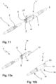
- FIG 11 a first embodiment according to the invention of a separated draft limiting element 1 is shown.
- This draft limiting element 1 has a security element 10.
- the first recording device 2 is equipped with a locking lug 5, which can cooperate with a corresponding locking edge 28 of the second recording device 6.
- the second receiving device 6 in turn has a receiving body 7 with a collet 9 with tongues 8.
- the locking edge 28 is arranged in an opening in the tongue 8.
- a sleeve is provided as a securing element 10, which is rotatable about an axis of rotation D on the collet.
- the securing element 10 has a recess which leaves the tongue 8 free in the state shown, so that the tongue 8 is freely movable. By turning the securing element 10 in the direction of the arrow, the tongue 8 can be blocked so that the tension limiting element 1 ensures a firm connection.
- the Figure 12a shows a modified train limiting element 1 'according to Figure 11 , whereby the receiving body 7 of the second receiving device 6 (see Figure 11 ) was replaced by a pull-in head 41.
- the recording device 6 off Figure 11 becomes a pull-in aid 40, which, however, is identical to the receiving device 6 Figure 11 is provided with a collet 9 with tongues 8 and a securing element 10.
- Figure 12b is the modified train limiting element 1 ' Figure 12b shown in assembled state.
- the securing element 10 is rotated so that the first receiving device 2 is firmly connected to the pull-in aid 40.
- This function is particularly important when pulling a cable into a cable duct or installation pipe.
- the pull-in head 41 is provided with an opening 42.
Description
Die vorliegende Erfindung betrifft ein Zugbegrenzungselement für eine faseroptische Verbindung, sowie ein Patchcord und ein Pigtail mit einem Zugbegrenzungselement.The present invention relates to a tension limiting element for a fiber optic connection, as well as a patch cord and a pigtail with a tension limiting element.
Aus dem Stand der Technik sind faseroptische Verbinder, insbesondere Steckverbinder bekannt. Diese Verbinder erlauben ein einfaches Erstellen einer faseroptischen Verbindung, welche sogar von einem Laien erstellt werden kann. Aufgrund der immer höheren Datenmenge, welche selbst in privaten Haushalten erforderlich ist, wird vielerorts bereits das Glasfasernetz bis ins Haus bzw. in die Wohnung installiert, so dass ein Breitbandanschluss zur Verfügung steht. Selbst Endgeräte werden schon direkt an das Glasfasernetz angeschlossen. Herkömmliche faseroptische Verbinder verfügen meist über eine formschlüssige Verriegelung, so dass keine ungewollte Trennung der faseroptischen Verbindung erfolgen kann. Werden nun solche Verbinder auch in Heimanwendungen eingesetzt, besteht einerseits ein erhebliches Verletzungsrisiko, da solche faseroptischen Verbindungen als Stolperfallen wirken können und die Verbindung bei übermässiger Zugbelastung am Verbinder nicht getrennt wird. Auf der anderen Seite kann es vorkommen, dass durch solche Stolperunfälle das Endgerät oder aber die Installationsdose in der Zimmerwand beschädigt wird. Sowohl Beschädigungen am Endgerät als auch an der Installationsdose führen zu langwierigen und kostenintensiven Reparaturen. Der Benutzer kann das entsprechende Endgerät oder aber den Breitbandanschluss bis nach erfolgter Reparatur nicht mehr nutzen.Fiber optic connectors, in particular plug connectors, are known from the prior art. These connectors allow you to easily create a fiber optic connection that can even be created by a layperson. Due to the ever-increasing amount of data required even in private households, in many places the fiber optic network is already being installed into the house or apartment so that a broadband connection is available. Even end devices are already connected directly to the fiber optic network. Conventional fiber-optic connectors usually have a positive lock so that the fiber-optic connection cannot be accidentally separated. If such connectors are now also used in home applications, there is, on the one hand, a considerable risk of injury, since such fiber-optic connections can act as tripping hazards and the connection will not be separated if there is excessive tensile load on the connector. On the other hand, it can happen that such tripping accidents damage the end device or the installation box in the room wall. Damage to both the end device and the installation box leads to lengthy and costly repairs. The user can no longer use the corresponding device or the broadband connection until the repair has been carried out.
Es ist Aufgabe der Erfindung, die Nachteile des Standes der Technik zu überwinden. Insbesondere soll ein Zugbegrenzungselement für eine faseroptische Verbindungsleitung, sowie ein Patchcord und ein Pigtail mit einem Zugbegrenzungselement zur Verfügung gestellt werden, welches bei Überschreiten einer maximal zulässigen Zugkraft die faseroptische Verbindung trennt.It is the object of the invention to overcome the disadvantages of the prior art. In particular, a tension-limiting element for a fiber-optic connecting line, as well as a patch cord and a pigtail with a tension-limiting element are to be provided, which separates the fiber-optic connection when a maximum permissible tensile force is exceeded.
Diese Aufgabe wird durch ein Zugbegrenzungselement gemäss Anspruch 1, sowie durch ein Patchcord und ein Pigtail gemäss den Ansprüchen 15 und 16 gelöst. Weitere Ausführungsformen ergeben sich aus den abhängigen Patentansprüchen.This task is achieved by a train limiting element according to
Ein erfindungsgemässes Zugbegrenzungselement für eine faseroptische Verbindung enthält mindestens eine erste und eine zweite Aufnahmevorrichtung, sowie Mittel, welche eine Trennung der faseroptischen Verbindung an einem vordefinierten Ort erlauben. Dabei weisen beide Aufnahmevorrichtungen einen Aufnahmekörper auf. Dieser Aufnahmekörper umfasst eine Aufnahme zum Aufnehmen und Fixieren einer oder mehrerer optischen Fasern parallel zu einer Achsrichtung sowie Verbindungsmittel zum Verbinden der ersten mit der zweiten Aufnahmevorrichtung. Die Verbindungsmittel sind so ausgestaltet, dass die Verbindung zwischen der ersten und zweiten Aufnahmevorrichtung unter Einwirkung einer vorbestimmten oder vorbestimmbaren Zugkraft trennbar ist. Es ist insbesondere denkbar, dass die Zugkraft innerhalb vorgegebener Grenzen individuell eingestellt oder einstellbar ist. So kann beispielsweise die Zugkraft zwischen 5 und 30 N, bevorzugt zwischen 10 und 25 N, besonders bevorzugt zwischen 15 und 20 N eingestellt oder einstellbar sein. Der Aufnahmekörper der einen Aufnahmevorrichtung weist eine Spannzange mit Schlitzen und mehreren Zungen auf und die Verbindungsmittel sind an der Zunge der Spannzange angeordnet. Unter einer Spannzange wird hier und im Folgenden jedes Mittel verstanden, welches ein Gegenstück umschliesst und dabei so geschlitzt ist, dass sein Innendurchmesser mindestens in einem Teilbereich veränderbar ist. Die in der Zugbegrenzung angeordnete Faser wird durch die Spannzange optimal vor Ausseneinflüssen geschützt. Ausserdem wird mit einer Spannzange ein einfaches Verbinden der beiden Aufnahmevorrichtungen ermöglicht.A tension limiting element according to the invention for a fiber-optic connection contains at least a first and a second receiving device, as well as means which allow the fiber-optic connection to be separated at a predefined location. Both receiving devices have a receiving body. This receiving body comprises a receptacle for receiving and fixing one or more optical fibers parallel to an axial direction and connecting means for connecting the first to the second receiving device. The connecting means are designed in such a way that the connection between the first and second receiving devices can be separated under the influence of a predetermined or predeterminable tensile force. It is particularly conceivable that the tensile force is individually set or adjustable within predetermined limits. So can For example, the tensile force can be set or adjustable between 5 and 30 N, preferably between 10 and 25 N, particularly preferably between 15 and 20 N. The receiving body of one receiving device has a collet with slots and several tongues and the connecting means are arranged on the tongue of the collet. Here and below, a collet is understood to mean any means that encloses a counterpart and is slotted in such a way that its inner diameter can be changed at least in a partial area. The fiber arranged in the tension limiter is optimally protected from external influences by the collet. In addition, a collet chuck makes it possible to easily connect the two holding devices.
Die Verbindungsmittel können Rastmittel sein. Somit wird eine einfache Installation der Zugbegrenzung ermöglicht. Die Verbindungsmittel können jedoch auch alternative Formen aufweisen, wie beispielsweise eine Magnetverbindung oder eine stoffschlüssige Verbindung mit Sollbruchstellen.The connecting means can be locking means. This enables easy installation of the draft limiter. However, the connecting means can also have alternative forms, such as a magnetic connection or a material connection with predetermined breaking points.
Mindestens ein Verbindungsmittel des Aufnahmekörpers der ersten Aufnahmevorrichtung kann eine Rastnase aufweisen. Diese Rastnase steht vorzugsweise von einer Aussenfläche des Aufnahmekörpers vor und ist mindestens teilweise umlaufend ausgebildet. Entsprechend kann mindestens ein Verbindungsmittel des Aufnahmekörpers der zweiten Aufnahmevorrichtung eine Rastkante aufweisen, welche mit der Rastnase der ersten Aufnahmevorrichtung verrastbar ist. Es versteht sich von selbst, dass die Rastnase bzw. die Rastkante auch auf dem Aufnahmekörper der anderen Aufnahmevorrichtung angeordnet sein kann. Anstelle einer Kombination von Rastnase und Rastkante sind beispielsweise eine halbkugelförmige vorstehende Struktur und eine entsprechende Ausnehmung im gegenüberliegenden Aufnahmekörpers denkbar. Ausserdem ist es denkbar, dass beide Aufnahmekörper je über eine Kombination aus Rastnase und Rastkante verfügen. Rastnase und Rastkante sind dann an jedem Aufnahmekörper versetzt angeordnet. Selbstverständlich sind die Rastnase und die Rastkante der beiden Aufnahmekörper zueinander ausgerichtet, so dass eine Rastverbindung erstellt werden kann. Die Rastnase und/oder die Rastkante können rampenförmig ausgebildet sein. Durch den Neigungswinkel der Rampe kann die Entriegelungskraft des Verbindungsmittels und somit auch die maximal vom Zugbegrenzungselement aufnehmbare Zugkraft beeinflusst werden. Dieser Neigungswinkel beträgt vorzugsweise zwischen 45° und 60°. Selbstverständlich kann diese Entriegelungskraft auch durch andere Mittel wie beispielsweise die Dimensionierung der Zunge oder das verwendete Material kontrolliert werden.At least one connecting means of the receiving body of the first receiving device can have a locking lug. This locking lug preferably projects from an outer surface of the receiving body and is at least partially circumferential. Accordingly, at least one connecting means of the receiving body of the second receiving device can have a locking edge which can be locked with the locking lug of the first receiving device. It goes without saying that the locking lug or the locking edge can also be arranged on the receiving body of the other receiving device. Instead of a combination of locking lug and locking edge, for example, a hemispherical projecting structure and a corresponding recess in the opposite receiving body are conceivable. Furthermore, it is conceivable that both receiving bodies each have a combination of locking lug and locking edge. The locking lug and locking edge are then arranged offset on each receiving body. Of course, the locking lug and the locking edge of the two receiving bodies are aligned with one another so that a locking connection can be created. The locking lug and/or the locking edge can be designed in a ramp shape. The unlocking force of the connecting means and thus also the maximum tensile force that can be absorbed by the tension limiting element can be influenced by the angle of inclination of the ramp. This angle of inclination is preferably between 45° and 60°. Of course, this unlocking force can also be controlled by other means such as the dimensioning of the tongue or the material used.
Die Zunge kann aus einem elastischen Material, vorzugsweise aus Kunststoff, besonders bevorzugt aus Polyamid (PA) oder Polyetherimid (PEI) bestehen. Andere Materialien sind ebenfalls denkbar. Durch eine geeignete Materialwahl kombiniert mit der konstruktiven Ausgestaltung, insbesondere der Dicke und der Länge der Zunge kann, wie bereits erwähnt, die für die Trennung der optischen Verbindung benötigte Zugkraft eingestellt werden.The tongue can consist of an elastic material, preferably plastic, particularly preferably polyamide (PA) or polyetherimide (PEI). Other materials are also conceivable. As already mentioned, the tensile force required for separating the optical connection can be adjusted through a suitable choice of material combined with the structural design, in particular the thickness and length of the tongue.
Ein Sicherungselement ist um eine in Achsrichtung verlaufende Drehachse drehbar über der Zunge angeordnet, so dass die Klemmkraft der Zunge dann je nach Ausrichtung beeinflussbar ist. Ein hülsenförmiges Sicherungselement würde dann über eine Ausnehmung verfügen, welche entsprechend der Zunge angeordnet ist. Die Klemmkraft der Zunge würde dann entsprechend der Drehposition der Ausnehmung beeinflusst.A securing element is arranged above the tongue so as to be rotatable about an axis of rotation running in the axial direction, so that the clamping force of the tongue can then be influenced depending on the orientation. A sleeve-shaped securing element would then have a recess which is arranged corresponding to the tongue. The clamping force of the tongue would then be influenced according to the rotational position of the recess.
Das Sicherungselement ist in eine offene Position verdrehbar, in der kein Einfluss auf die Klemmkraft der Zunge ausgeübt wird. Eine solche Position ist insbesondere für die Montage der Zugbegrenzung vorteilhaft, weil dann die Verbindungsmittel auch beim Zusammenbau die geringste Kraft ausüben. Entsprechend ist das Sicherungselement in eine Schliessposition verdrehbar, wo jede Bewegung der Zunge blockiert wird. In einer solchen Schliessposition überdeckt das Sicherungselement die Zunge komplett. Selbstverständlich kann das Sicherungselement jede Lage zwischen der offenen Position und der Schliessposition einnehmen, so dass die Zugkraft stufenlos eingestellt werden kann.The securing element can be rotated into an open position in which no influence is exerted on the clamping force of the tongue. Such a position is particularly advantageous for assembling the tension limiter because the connecting means then exert the least force during assembly. Accordingly, the securing element can be rotated into a closed position, where any movement of the tongue is blocked. In such a closed position, the securing element completely covers the tongue. Of course, the securing element can assume any position between the open position and the closed position, so that the tensile force can be adjusted continuously.
Die Aufnahmekörper können einen Befestigungsbereich, insbesondere einen Crimphals, zum Befestigen einer Zugentlastung eines faseroptischen Kabels aufweisen. Durch einen solchen Befestigungsbereich wir sichergestellt, dass eine auf die Zugbegrenzung wirkende Zugspannung, welche kleiner als die zum Trennen benötigte Zugkraft ist, nicht auf die Faser einwirkt und gegebenenfalls eine Verschlechterung der Übertragungsqualität bewirkt oder gar die Faser beschädigt. Es ist jedoch auch denkbar, dass die Zugbegrenzung nicht mit einem faseroptischen Kabel mit Zugentlastung, sondern nur mit einer Faser, welche eine einfache Kunststoffummantelung aufweist bestückt wird.The receiving bodies can have a fastening area, in particular a crimp neck, for fastening a strain relief of a fiber optic cable. Such a fastening area ensures that a tensile stress acting on the tension limiter, which is smaller than the tensile force required for separation, does not act on the fiber and possibly cause a deterioration in the transmission quality or even damage the fiber. However, it is also conceivable that the strain limiter is not equipped with a fiber-optic cable with strain relief, but only with a fiber that has a simple plastic coating.
Jede Aufnahme zum Aufnehmen und Fixieren einer oder mehrerer optischen Fasern kann mindestens eine herkömmliche Ferrule umfassen. Ausserdem können diese Ferrulen entsprechend die Mittel zur Trennung der faseroptischen Verbindung sein. Unter einer herkömmlichen Ferrule wird beispielsweise ein Steckerstift mit mindestens einer Bohrung zur Aufnahme einer optischen Faser verstanden. Bekannt sind insbesondere die Ferrulen mit einem Aussendurchmesser von 2.5mm und 1.25mm für Glasfasern. Ebenso wird aber unter einer Ferrule beispielsweise auch eine MT-Ferrule verstanden, welche insbesondere zwei oder mehrere Fasern aufnehmen kann. Selbstverständlich kann eine Ferrule auch eine andere Form aufweisen und/oder insbesondere auch für Kunststofffasern ausgebildet sein. Es versteht sich von selbst, dass die Endflächen der Ferrulen und entsprechen auch der optischen Fasern so bearbeitet sein müssen, dass eine dem Anwendungszweck entsprechende Datenübertragung gewährleistet werden kann. Dadurch, dass Ferrulen zum Erstellen und Trennen der optischen Verbindung verwendet werden, kann das Zugbegrenzungselement nach einer durch übermässige Zuglast bewirkten Trennung wieder verwendet werden und die optische Verbindung bei entsprechender Ausgestaltung der Aufnahmevorrichtungen einfach durch Zusammenstecken wieder erstellt werden.Each receptacle for receiving and fixing one or more optical fibers can include at least one conventional ferrule. In addition, these ferrules can be the means for separating the fiber-optic connection. Under a conventional Ferrule is, for example, a connector pin with at least one hole for receiving an optical fiber. Ferrules with an outer diameter of 2.5mm and 1.25mm for glass fibers are particularly well known. However, a ferrule is also understood to mean, for example, an MT ferrule, which can in particular accommodate two or more fibers. Of course, a ferrule can also have a different shape and/or in particular be designed for plastic fibers. It goes without saying that the end surfaces of the ferrules and also the optical fibers must be processed in such a way that data transmission can be ensured in accordance with the intended application. Because ferrules are used to create and separate the optical connection, the tension limiting element can be used again after a separation caused by excessive tensile load and the optical connection can be recreated simply by plugging it together if the receiving devices are designed accordingly.
Die Ferrule der Aufnahme der ersten Aufnahmevorrichtung kann fest mit dem Aufnahmekörper verbunden sein. Bei optischen Verbindungen mit Ferrulen müssen die Ferrulen mit ihren Endflächen mit einem genau definierten Druck aufeinander treffen, um eine geeignete Übertragungsqualität zu ermöglichen. Um diesen Druck zu gewährleisten kann die Ferrule der Aufnahme der zweiten Aufnahmevorrichtung in Achsrichtung federnd mit dem Aufnahmekörper verbunden sein. Es versteht sich von selbst, dass hier wiederum die gefederte bzw. die fest verbundene Ferrule vertauscht werden können. Ebenso ist es denkbar, dass beide Ferrulen federnd mit dem entsprechenden Aufnahmekörper verbunden sind.The ferrule of the receptacle of the first receptacle can be firmly connected to the receptacle body. In the case of optical connections with ferrules, the end faces of the ferrules must meet each other with a precisely defined pressure in order to enable suitable transmission quality. In order to ensure this pressure, the ferrule of the receptacle of the second receptacle can be resiliently connected to the receptacle body in the axial direction. It goes without saying that the spring-loaded or firmly connected ferrule can be swapped here. It is also conceivable that both ferrules are resiliently connected to the corresponding receiving body.
Wie bei optischen Verbindern mit Ferrulen üblich, können die Ferrulen mittels einer oder mehrerer Führungshülsen aufeinander ausgerichtet sein. Solche Führungshülsen sind dem Fachmann insbesondere für Ferrulen mit einem Durchmesser von 2.5mm bzw. 1.25mm als geschlitzte Hülsen, so genannte Sleeves bekannt. Die Führungshülse kann am Aufnahmekörper der fixen Ferrule befestigt sein.As is usual with optical connectors with ferrules, the ferrules can be placed on one another using one or more guide sleeves be aligned. Such guide sleeves are known to those skilled in the art, particularly for ferrules with a diameter of 2.5mm or 1.25mm, as slotted sleeves, so-called sleeves. The guide sleeve can be attached to the receiving body of the fixed ferrule.
Alternativ zu einer Ferrule kann die erste Aufnahmevorrichtung ein Mittel umfasst, welches beim Trennen der ersten von der zweiten Aufnahmevorrichtung eine im Zugbegrenzungselement angeordnete optische Faser durchtrennt. Dabei ist es nicht relevant, ob dieses Mittel in der ersten oder der zweiten Aufnahmevorrichtung angeordnet ist. Der Aufnahmekörper kann dabei direkt so ausgestaltet sein, dass er als Aufnahme für die Fasern dient. Eine solche Lösung kann unabhängig von der vorab genannten Lösung der Spannzange realisiert werden.As an alternative to a ferrule, the first receiving device can comprise a means which, when the first receiving device is separated from the second receiving device, cuts through an optical fiber arranged in the tension limiting element. It is not relevant whether this means is arranged in the first or the second receiving device. The receiving body can be designed directly in such a way that it serves as a receptacle for the fibers. Such a solution can be implemented independently of the collet chuck solution mentioned above.
Das Mittel zum Trennen der optischen Faser kann eine Klinge sein, welche quer zu zur Achsrichtung bewegbar ist. Dabei kann die Klinge ein Blechbiegeteil, vorzugsweise aus einem Federstahl, sein. Neben einer Klinge zum Durchtrennen der Faser sind auch andere Mittel denkbar. Beispielsweise könnten Scherkräfte auf die Faser einwirken, welche die Faser zum Brechen bringen. Die Faser könnte aber auch angeritzt und unter Zug gesetzt werden, was ebenfalls zu einem Faserbruch führen würde.The means for separating the optical fiber may be a blade which is movable transversely to the axial direction. The blade can be a bent sheet metal part, preferably made of spring steel. In addition to a blade for cutting through the fiber, other means are also conceivable. For example, shearing forces could act on the fiber, causing the fiber to break. However, the fiber could also be scratched and put under tension, which would also lead to fiber breakage.
Die Klinge kann am Aufnahmekörper der ersten Aufnahmevorrichtung angeordnet sein und die zweite Aufnahmevorrichtung kann eine Rampe aufweisen. Diese Rampe könnte so ausgestaltet sein, dass beim Trennen der beiden Aufnahmevorrichtungen die Rampe mit der Klinge derart in Wirkverbindung bringbar ist, dass die Klinge verschoben wird und eine im Zugbegrenzungselement angeordnete Faser durchtrennbar ist. Es versteht sich wiederum von selbst, dass Klinge und Rampe vertauschbar sind.The blade can be arranged on the receiving body of the first receiving device and the second receiving device can have a ramp. This ramp could be designed in such a way that when the two receiving devices are separated, the ramp can be brought into operative connection with the blade in such a way that the blade is displaced and a fiber arranged in the tension limiting element can be severed. It goes without saying that the blade and ramp are interchangeable.
Der Aufnahmekörper einer Aufnahmevorrichtung kann ersetzbar sein durch einen Einziehkopf, wobei der Einziehkopf ein Befestigungselement zum Befestigen einer Einzuglitze aufweist. Ein derart modifiziertes Zugbegrenzungselement dient zwar nicht mehr der Trennung einer faseroptischen Verbindungsleitung, kann jedoch beispielsweise als Schutzvorrichtung dienen, wenn eine vormontierte optische Faser in einen Kabelkanal oder in ein Installationsrohr eingezogen werden soll. Das Befestigungsmittel am Einziehkopf kann beispielsweise als Bohrung oder Öffnung quer zur Achsrichtung ausgestaltet sein.The receiving body of a receiving device can be replaced by a pull-in head, the pull-in head having a fastening element for attaching a pull-in strand. Although a tension limiting element modified in this way no longer serves to separate a fiber-optic connecting line, it can, for example, serve as a protective device if a pre-assembled optical fiber is to be pulled into a cable duct or into an installation pipe. The fastening means on the pull-in head can be designed, for example, as a bore or opening transverse to the axial direction.
Ein erfindungsgemässes Patchcord umfasst ein faseroptisches Kabel mit beidseitig angeordneten faseroptischen Verbindern, sowie zwischen den beiden Verbindern ein Zugbegrenzungselement wie vorgängig beschrieben und in Anspruch 1 definiert.A patch cord according to the invention comprises a fiber-optic cable with fiber-optic connectors arranged on both sides, and between the two connectors a tension-limiting element as described above and defined in
Ein solches Patchcord kann ähnlich einem elektrischen CAT5-Netzwerk-Patchkabel von einem Heimanwender direkt mit einem entsprechen ausgerüsteten Endgerät sowie mit einer entsprechenden Datendose verbunden werden. Somit wird bei übermässiger Zug-Beanspruchung die faseroptische Verbindung getrennt, bevor die Datendose oder das Endgerät beschädigt werden. Ein erfindungsgemässes Pigtail umfasst ein faseroptisches Kabel mit einem einseitig angeordneten faseroptischen Verbinder sowie ein auf dem faseroptischen Kabel, vorzugsweise nahe am faseroptischen Verbinder angebrachtes Zugbegrenzungselement, wie vorgängig beschrieben und in Anspruch 1 definiert.Similar to an electrical CAT5 network patch cable, such a patch cord can be connected by a home user directly to an appropriately equipped end device and to a corresponding data socket. This means that if there is excessive tensile stress, the fiber optic connection is separated before the data socket or the terminal device is damaged. A pigtail according to the invention comprises a fiber-optic cable with a fiber-optic connector arranged on one side and a tension limiting element mounted on the fiber-optic cable, preferably close to the fiber-optic connector, as described above and defined in
Dabei wird unter nah ein Bereich von 0mm bis 1000mm, vorzugsweise 50mm bis 500mm, besonders bevorzugt 100mm bis 250mm verstanden.The term close is understood to mean a range from 0mm to 1000mm, preferably 50mm to 500mm, particularly preferably 100mm to 250mm.
Anhand von Figuren wird die Erfindung im Folgenden näher erläutert. Es zeigen:
- Figur 1:
- ein nicht erfindungsgemässes Zugbegrenzungselement konfektioniert auf einem faseroptischen Kabel, wobei sich ein Sicherungselement in einer Schliessposition befindet,
- Figur 2:
- das
Zugbegrenzungselement gemäss Figur 1 , wobei Knickschutztüllen abgezogen sind und sich das Sicherungselement in einer offenen Position befindet, - Figur 3:
- eine erste Ausführungsform eines nicht erfindungsgemässen Zugbegrenzungselementes in einer Explosionszeichnung,
- Figur 4:
- das
Zugbegrenzungselement aus Figur 3 nach der Trennung der optischen Verbindung durch Überschreiten der eingestellten Zugkraft, - Figur 5a:
- einen Längsschnitt durch das fertig konfektionierte Zugbegrenzungselement gemäss
Figur 3 , - Figur 5b:
- eine Detailansicht auf den Bereich A gemäss
Figur 5a , - Figur 6:
- eine zweite Ausführungsform eines nicht erfindungsgemässen Zugbegrenzungselementes in einer Explosionszeichnung,
- Figur 7:
- das
Zugbegrenzungselement aus Figur 6 , einseitig fertig konfektioniert, jedoch noch nicht zusammengesteckt, - Figur 8:
- das
Zugbegrenzungselement aus Figur 6 nach der Trennung der optischen Verbindung durch Überschreiten der eingestellten Zugkraft, - Figur 9:
- einen Längsschnitt durch das fertig konfektionierte Zugbegrenzungselement gemäss
Figur 6 , - Figur 10:
- ein aufgetrenntes Zugbegrenzungselement in einer Ausführungsform ohne Sicherungselement,
- Figur 11:
- eine Ausführungsform eines aufgetrennten Zugbegrenzungselementes mit Sicherungselement gemäss der Erfindung
- Figur 12a:
- ein Zugbegrenzungselement mit einer Einziehhilfe vor dem Verbinden, und
- Figur 12b:
- das Zugbegrenzungselement gemäss
Figur 12a bereit zum Einziehen.
- Figure 1:
- a tension limiting element not according to the invention assembled on a fiber-optic cable, with a securing element being in a closed position,
- Figure 2:
- the train limiting element according to
Figure 1 , with the anti-kink grommets removed and the securing element in an open position, - Figure 3:
- a first embodiment of a draft limiting element not according to the invention in an exploded drawing,
- Figure 4:
- the draft limiting element
Figure 3 after the optical connection has been separated by exceeding the set tensile force, - Figure 5a:
- a longitudinal section through the finished tension limiting element according to
Figure 3 , - Figure 5b:
- a detailed view of area A according to
Figure 5a , - Figure 6:
- a second embodiment of a draft limiting element not according to the invention in an exploded drawing,
- Figure 7:
- the draft limiting element
Figure 6 , ready-made on one side, but not yet put together, - Figure 8:
- the draft limiting element
Figure 6 after the optical connection has been separated by exceeding the set tensile force, - Figure 9:
- a longitudinal section through the finished tension limiting element according to
Figure 6 , - Figure 10:
- a separated train limiting element in an embodiment without a securing element,
- Figure 11:
- an embodiment of a separated draft limiting element with a securing element according to the invention
- Figure 12a:
- a tension limiting element with a pull-in aid before connecting, and
- Figure 12b:
- the train limiting element according to
Figure 12a ready to move in.
In
In der
Die
Dargestellt in
In der
In der gezeigten Darstellung ist das Sicherungselement 10 in einer offenen Position 11, so dass es keinen oder nur einen geringen Einfluss auf die Zugkraft hat. Die Zugkraft ist somit nur durch die Materialwahl der Spannzange 9 bzw. der Zungen 8, sowie durch die mechanische Ausgestaltung der Zungen 8 und der Rastnase 5 abhängig.In the illustration shown, the securing
In
Die
In
Claims (16)
- Tension limiting element (1) for a fibre optic connection line:- a first and a second receiving device (2, 6),- Means that allow the fibre optic connection to be disconnected at a predefined location,wherein the first and the second receiving device (2, 6) each have a receiving body (3, 7) which- has a holder for receiving and fixing one or more optical fibres (30, 30') parallel to an axial direction (R) and- connecting means for connecting the first to the second receiving device (2, 6),wherein the connecting means are designed such that the connection between the first and second receiving devices (2, 6) can be separated under the action of a predetermined or predeterminable tensile force,wherein the receiving body (7) of one receiving device (6) has a collet chuck (9) with slots and a plurality of tongues (8) and the connecting means are arranged on the tongue (8) of the collet chuck (9), wherein the collet chuck (9) of the one holding device (6) and a counterpart of the other holding device (2) are designed in such a way that the collet chuck (9) can enclose the counterpart, wherein the collet chuck (9) is slotted in such a way that an internal diameter of the collet chuck (9) can be varied at least in a partial region,characterised in that a securing element (10) rotatable about an axis of rotation (D) extending in the axial direction (R) is arranged above the tongue (8), so that a clamping force of the tongues (8) can be influenced depending on the position of the securing element (10), wherein the securing element (10) can be rotated into an open position (11), in which no influence is exerted on the clamping force of the tongues (8), and into a closed position (12), where any movement of the tongues (8) is blocked.
- Tension limiting element (1) according to claim 1, characterised in that the connecting means are latching means.
- Tension limiting element (1) according to claim 1 or 2, characterised in that at least one connecting means of the receiving body (3) of the first receiving device (2) has a latching lug (5) which projects from an outer surface (4) of the receiving body (3) and is designed to be at least partially circumferential.
- Tension limiting element (1) according to claim 3, characterised in that at least one connecting means of the receiving body (7) of the second receiving device (6) has a latching edge (28) which can be latched to the latching lug (5) of the first receiving device (2).
- Tension limiting element (1) according to one of claims 1 to 4, characterised in that the tongue (8) consists of an elastic material, preferably of plastic, particularly preferably of polyamide (PA) or polyetherimide (PEI).
- Tension limiting element (1) according to one of claims 1 to 5, characterised in that the receiving bodies (3, 7) have a fastening region (19) for fastening a strain relief of a fibre-optic cable (33).
- A tension limiting element (1) according to any one of claims 1 to 6, characterised in that each receptacle for receiving and fixing one or more optical fibres comprises at least one conventional ferrule (14, 14') and in that these ferrules (14, 14') are the means for separating the optical fibre connection.
- Tension limiting element (1) according to claim 7, characterised in that the ferrule (14) of the receptacle of the first receiving device (2) is firmly connected to the receiving body (3) .
- Tension limiting element (1) according to claim 7 or 8, characterised in that the ferrule (14') of the receptacle of the second receiving device (6) is resiliently connected to the receiving body (7) in the axial direction (R).
- Tension limiting element (1) according to one of claims 7 to 9, characterised in that the ferrules (14, 14') are aligned with one another by means of one or more guide sleeves (16).
- Tension limiting element (1) according to one of claims 1 to 6, characterised in that the first receiving device (2) comprises a means which, when separating the first from the second receiving device (6), cuts through an optical fibre (30, 30') arranged in the tension limiting element (1).
- Tension limiting element (1) according to claim 11, characterised in that the means for separating the optical fibre is a blade (17) which is movable transversely to the axial direction (R).
- Tension limiting element (1) according to claim 12, characterised in that the blade (17) is a sheet metal bending part, preferably made of a spring steel.
- Tension limiting element (1) according to claim 12 or 13, characterised in that the blade (17) is arranged on the receiving body (3) of the first receiving device (2) and the second receiving device (6) has a ramp (18) which, when the two receiving devices (2, 6) are separated, can be brought into operative connection with the blade (17) in such a way that a fibre (30, 30') arranged in the tension limiting element (1) can be severed.
- Patch cord consisting of a fibre-optic cable (33) with fibre-optic connectors arranged on both sides, characterised in that a tension limiting element (1) according to one of claims 1 to 14 is arranged between the two connectors.
- Pigtail consisting of a fibre-optic cable (33) with a fibre-optic connector arranged at one end, characterised in that a tension limiting element (1) according to one of claims 1 to 14 is arranged on the fibre-optic cable (33), preferably close to the fibre-optic connector.
Applications Claiming Priority (1)
| Application Number | Priority Date | Filing Date | Title |
|---|---|---|---|
| CH00156/11A CH704400A1 (en) | 2011-01-28 | 2011-01-28 | Zugbegrenzungselement for a fiber optic link, and patch cord and pigtail with this Zugbegrenzungselement. |
Publications (3)
| Publication Number | Publication Date |
|---|---|
| EP2482109A2 EP2482109A2 (en) | 2012-08-01 |
| EP2482109A3 EP2482109A3 (en) | 2012-09-26 |
| EP2482109B1 true EP2482109B1 (en) | 2024-03-13 |
Family
ID=45375266
Family Applications (1)
| Application Number | Title | Priority Date | Filing Date |
|---|---|---|---|
| EP12150005.2A Active EP2482109B1 (en) | 2011-01-28 | 2012-01-02 | Traction limiting element for a fibre optic connection, patch cable and pigtail with this traction limiting element |
Country Status (2)
| Country | Link |
|---|---|
| EP (1) | EP2482109B1 (en) |
| CH (1) | CH704400A1 (en) |
Families Citing this family (12)
| Publication number | Priority date | Publication date | Assignee | Title |
|---|---|---|---|---|
| CN104823090B (en) | 2012-11-30 | 2017-04-05 | 泰科电子公司 | The joints of optical fibre with field-attachable outconnector housing |
| DE102013105779A1 (en) * | 2013-06-05 | 2014-12-11 | Reichle & De-Massari Ag | connector device |
| CN104808295B (en) | 2014-01-29 | 2017-01-11 | 泰科电子(上海)有限公司 | Cable traction assembly and assembling and disassembly method thereof |
| CN104849815B (en) | 2014-02-14 | 2017-01-18 | 泰科电子(上海)有限公司 | Optical fiber connector and assembly method therefor |
| CN104849816B (en) | 2014-02-14 | 2017-01-11 | 泰科电子(上海)有限公司 | Optical fiber connector and assembly method therefor |
| CN105445862B (en) | 2014-07-09 | 2018-01-19 | 泰科电子(上海)有限公司 | The joints of optical fibre and its on-site assembly method |
| WO2017095928A1 (en) | 2015-11-30 | 2017-06-08 | Commscope Technologies Llc | Fiber optic connector and assembly thereof |
| US10641970B2 (en) | 2015-12-16 | 2020-05-05 | Commscope Technologies Llc | Field installed fiber optic connector |
| EP3270200A1 (en) | 2016-07-14 | 2018-01-17 | Diamond SA | Adapter part for receiving a connector part and optical module |
| DE202019001267U1 (en) | 2019-03-19 | 2020-06-25 | Hauff-Technik Gmbh & Co. Kg | Junction box device |
| DE102019007483A1 (en) | 2018-11-29 | 2020-06-04 | Hauff-Technik Gmbh & Co. Kg | Junction box device |
| EP3660990B1 (en) | 2018-11-29 | 2024-01-10 | Hauff-Technik GmbH & Co. KG | Method for providing a data cable connection |
Citations (2)
| Publication number | Priority date | Publication date | Assignee | Title |
|---|---|---|---|---|
| JPS59126508A (en) * | 1983-01-08 | 1984-07-21 | Sumitomo Electric Ind Ltd | Optical connector |
| US6152608A (en) * | 1998-04-10 | 2000-11-28 | Packard Hughes Interconnect Company | Snap lock connector for optical fiber systems |
Family Cites Families (7)
| Publication number | Priority date | Publication date | Assignee | Title |
|---|---|---|---|---|
| JPS60205511A (en) * | 1984-03-30 | 1985-10-17 | Nec Corp | Optical fiber connector |
| JPS60205512A (en) * | 1984-03-30 | 1985-10-17 | Nec Corp | Optical fiber connector |
| US4872736A (en) * | 1988-04-19 | 1989-10-10 | American Telephone And Telegraph Company, At&T Bell Laboratories | Connector assembly having a latching mechanism |
| CH684956A5 (en) * | 1991-04-23 | 1995-02-15 | Interlemo Holding Sa | connection device. |
| JP2000036346A (en) * | 1998-07-16 | 2000-02-02 | Sumitomo Wiring Syst Ltd | Connector for electric connections |
| DE29918358U1 (en) * | 1999-10-18 | 1999-12-23 | Rosenberger Hochfrequenztech | Coupler for coaxial connectors |
| US7654849B2 (en) * | 2007-03-22 | 2010-02-02 | Edwards Lifesciences Corporation | Releasably locking auto-aligning fiber optic connector |
-
2011
- 2011-01-28 CH CH00156/11A patent/CH704400A1/en unknown
-
2012
- 2012-01-02 EP EP12150005.2A patent/EP2482109B1/en active Active
Patent Citations (2)
| Publication number | Priority date | Publication date | Assignee | Title |
|---|---|---|---|---|
| JPS59126508A (en) * | 1983-01-08 | 1984-07-21 | Sumitomo Electric Ind Ltd | Optical connector |
| US6152608A (en) * | 1998-04-10 | 2000-11-28 | Packard Hughes Interconnect Company | Snap lock connector for optical fiber systems |
Also Published As
| Publication number | Publication date |
|---|---|
| EP2482109A2 (en) | 2012-08-01 |
| CH704400A1 (en) | 2012-07-31 |
| EP2482109A3 (en) | 2012-09-26 |
Similar Documents
| Publication | Publication Date | Title |
|---|---|---|
| EP2482109B1 (en) | Traction limiting element for a fibre optic connection, patch cable and pigtail with this traction limiting element | |
| EP1860473B1 (en) | Optical connector having a latchable and longitudinally movable holder in a mount part | |
| EP1254387B1 (en) | Optical connector for simultaneously connecting a plurality of fiber optical cables and adapter for said connector | |
| WO2004001471A1 (en) | Connector-plug part for an optical plug-in connection, method for connecting a connector-plug part to the end of an optical waveguide cable and device for carrying out said method | |
| EP3152809A2 (en) | Electric device | |
| CH703904A2 (en) | Connector. | |
| DE3517388A1 (en) | CONNECTING PART FOR A FIBER-OPTICAL CABLE | |
| WO2014146640A1 (en) | Clip-on elbow for a plug connector | |
| EP2115509B1 (en) | Plug parts for an optical plug connection | |
| EP3182186A1 (en) | Cable train interception element for optical fibre cable | |
| DE102006046181B4 (en) | Strain relief device for a fiber optic cable | |
| DE2824507C2 (en) | Connector for the electromagnetic coupling of optical fiber conductors | |
| WO2010124849A2 (en) | Plug for connecting fiber-optic cable connectors | |
| EP1493053A1 (en) | Fiber-optic plug comprising crimped knobs | |
| EP0373340B1 (en) | Demountable connector for coupling of two optical fibers | |
| DE10008613C2 (en) | Transition piece | |
| EP3255472A2 (en) | Cable retention element | |
| EP3152801B1 (en) | Contact retaining part with secured pull-out protection | |
| DE19851867C2 (en) | Device for the detachable connection of optical fibers to one another or to electro-optical transmitting and / or receiving devices | |
| DE102013112114B3 (en) | Insert for insertion into a connector part of a connector | |
| EP3190440A1 (en) | Optical fibre connection socket | |
| DE102008028518B4 (en) | Electrical plug device | |
| DE102013109951B4 (en) | Connector with a fuse element | |
| DE20317751U1 (en) | Process to manufacture a two-part connector for fiber optic cable using modified prior art connector housing | |
| DE10253390A1 (en) | Plug connector device has adapter for insertion into insertion opening with its plug-in end, especially reversibly, and for connection to bend protection element at other end |
Legal Events
| Date | Code | Title | Description |
|---|---|---|---|
| PUAI | Public reference made under article 153(3) epc to a published international application that has entered the european phase |
Free format text: ORIGINAL CODE: 0009012 |
|
| AK | Designated contracting states |
Kind code of ref document: A2 Designated state(s): AL AT BE BG CH CY CZ DE DK EE ES FI FR GB GR HR HU IE IS IT LI LT LU LV MC MK MT NL NO PL PT RO RS SE SI SK SM TR |
|
| AX | Request for extension of the european patent |
Extension state: BA ME |
|
| PUAL | Search report despatched |
Free format text: ORIGINAL CODE: 0009013 |
|
| AK | Designated contracting states |
Kind code of ref document: A3 Designated state(s): AL AT BE BG CH CY CZ DE DK EE ES FI FR GB GR HR HU IE IS IT LI LT LU LV MC MK MT NL NO PL PT RO RS SE SI SK SM TR |
|
| AX | Request for extension of the european patent |
Extension state: BA ME |
|
| RIC1 | Information provided on ipc code assigned before grant |
Ipc: G02B 6/38 20060101AFI20120822BHEP |
|
| 17P | Request for examination filed |
Effective date: 20130129 |
|
| STAA | Information on the status of an ep patent application or granted ep patent |
Free format text: STATUS: EXAMINATION IS IN PROGRESS |
|
| 17Q | First examination report despatched |
Effective date: 20170330 |
|
| STAA | Information on the status of an ep patent application or granted ep patent |
Free format text: STATUS: EXAMINATION IS IN PROGRESS |
|
| STAA | Information on the status of an ep patent application or granted ep patent |
Free format text: STATUS: EXAMINATION IS IN PROGRESS |
|
| GRAP | Despatch of communication of intention to grant a patent |
Free format text: ORIGINAL CODE: EPIDOSNIGR1 |
|
| STAA | Information on the status of an ep patent application or granted ep patent |
Free format text: STATUS: GRANT OF PATENT IS INTENDED |
|
| INTG | Intention to grant announced |
Effective date: 20231023 |
|
| GRAS | Grant fee paid |
Free format text: ORIGINAL CODE: EPIDOSNIGR3 |
|
| GRAA | (expected) grant |
Free format text: ORIGINAL CODE: 0009210 |
|
| STAA | Information on the status of an ep patent application or granted ep patent |
Free format text: STATUS: THE PATENT HAS BEEN GRANTED |
|
| AK | Designated contracting states |
Kind code of ref document: B1 Designated state(s): AL AT BE BG CH CY CZ DE DK EE ES FI FR GB GR HR HU IE IS IT LI LT LU LV MC MK MT NL NO PL PT RO RS SE SI SK SM TR |
|
| REG | Reference to a national code |
Ref country code: GB Ref legal event code: FG4D Free format text: NOT ENGLISH |
|
| REG | Reference to a national code |
Ref country code: CH Ref legal event code: EP |
|
| REG | Reference to a national code |
Ref country code: DE Ref legal event code: R096 Ref document number: 502012017250 Country of ref document: DE |