EP2482090A1 - System zur messung partieller entladungen in stromleitungen - Google Patents
System zur messung partieller entladungen in stromleitungen Download PDFInfo
- Publication number
- EP2482090A1 EP2482090A1 EP10818451A EP10818451A EP2482090A1 EP 2482090 A1 EP2482090 A1 EP 2482090A1 EP 10818451 A EP10818451 A EP 10818451A EP 10818451 A EP10818451 A EP 10818451A EP 2482090 A1 EP2482090 A1 EP 2482090A1
- Authority
- EP
- European Patent Office
- Prior art keywords
- cable
- power lines
- partial discharges
- inductive
- sensors
- Prior art date
- Legal status (The legal status is an assumption and is not a legal conclusion. Google has not performed a legal analysis and makes no representation as to the accuracy of the status listed.)
- Withdrawn
Links
Images


Classifications
-
- G—PHYSICS
- G01—MEASURING; TESTING
- G01R—MEASURING ELECTRIC VARIABLES; MEASURING MAGNETIC VARIABLES
- G01R31/00—Arrangements for testing electric properties; Arrangements for locating electric faults; Arrangements for electrical testing characterised by what is being tested not provided for elsewhere
- G01R31/12—Testing dielectric strength or breakdown voltage ; Testing or monitoring effectiveness or level of insulation, e.g. of a cable or of an apparatus, for example using partial discharge measurements; Electrostatic testing
- G01R31/1227—Testing dielectric strength or breakdown voltage ; Testing or monitoring effectiveness or level of insulation, e.g. of a cable or of an apparatus, for example using partial discharge measurements; Electrostatic testing of components, parts or materials
- G01R31/1263—Testing dielectric strength or breakdown voltage ; Testing or monitoring effectiveness or level of insulation, e.g. of a cable or of an apparatus, for example using partial discharge measurements; Electrostatic testing of components, parts or materials of solid or fluid materials, e.g. insulation films, bulk material; of semiconductors or LV electronic components or parts; of cable, line or wire insulation
- G01R31/1272—Testing dielectric strength or breakdown voltage ; Testing or monitoring effectiveness or level of insulation, e.g. of a cable or of an apparatus, for example using partial discharge measurements; Electrostatic testing of components, parts or materials of solid or fluid materials, e.g. insulation films, bulk material; of semiconductors or LV electronic components or parts; of cable, line or wire insulation of cable, line or wire insulation, e.g. using partial discharge measurements
-
- G—PHYSICS
- G01—MEASURING; TESTING
- G01R—MEASURING ELECTRIC VARIABLES; MEASURING MAGNETIC VARIABLES
- G01R15/00—Details of measuring arrangements of the types provided for in groups G01R17/00 - G01R29/00, G01R33/00 - G01R33/26 or G01R35/00
- G01R15/14—Adaptations providing voltage or current isolation, e.g. for high-voltage or high-current networks
- G01R15/142—Arrangements for simultaneous measurements of several parameters employing techniques covered by groups G01R15/14 - G01R15/26
-
- G—PHYSICS
- G01—MEASURING; TESTING
- G01R—MEASURING ELECTRIC VARIABLES; MEASURING MAGNETIC VARIABLES
- G01R31/00—Arrangements for testing electric properties; Arrangements for locating electric faults; Arrangements for electrical testing characterised by what is being tested not provided for elsewhere
- G01R31/12—Testing dielectric strength or breakdown voltage ; Testing or monitoring effectiveness or level of insulation, e.g. of a cable or of an apparatus, for example using partial discharge measurements; Electrostatic testing
-
- G—PHYSICS
- G01—MEASURING; TESTING
- G01R—MEASURING ELECTRIC VARIABLES; MEASURING MAGNETIC VARIABLES
- G01R31/00—Arrangements for testing electric properties; Arrangements for locating electric faults; Arrangements for electrical testing characterised by what is being tested not provided for elsewhere
- G01R31/50—Testing of electric apparatus, lines, cables or components for short-circuits, continuity, leakage current or incorrect line connections
Definitions
- the present invention refers to a system for measuring partial discharges in power lines that combines the use of two different sensors to determine the direction of movement of the discharge pulses produced In a power line, so that the area from which the electrical discharge comes can be determined in order to facilitate maintenance and repair thereof.
- the invention is applicable in mains of power distribution for high and medium voltage, and more particularly in lines connected to electric machines such as generator or transformer engines, so as to determine if the discharge pulses come from the line or electrical machine.
- the invention has developed a new system for measuring partial discharges in power lines that has the novelty of being based on the use of an inductive sensor, which is coupled to the cable to be measured by means of a magnetic field, and a capacitive sensor that is coupled to the cable to be measured by means of an electric field, so that both are connected to measurement device comprising means for detecting the polarity of the pulse picked up by the inductive sensor, means for detecting the polarity of the pulse picked up by the capacitive sensor and means for determining the direction of movement of the discharge pulses from the detectable polarities.
- the measurement device comprises means for storing an experimentally obtained table, which indicates the direction from which the partial discharge comes on the basis of the polarities detected from the inductive and capacitive sensors, so that after detecting the polarity of the partial discharge in the inductive sensor and capacitive sensor, the means for determining the polarity access the table and determine the direction in which the partial discharge has been produced (right or left of the point of measurement).
- the inductive and capacitive sensors are installed inside the power line record cell, so that the inductive sensor is installed in the ground wire of the bent end that is conventionally used to perform the connection of the cable to the cell isolator, and the capacitive sensor is installed in a rear plug provided in such bent end.
- the inductive sensor is installed embracing the cable shield.
- the invention enables performing the measurements discussed from outside the cell, whereby both the inductive and capacitive sensor are connected to both separate cables that end outside the cell by wall bushings, to which the measurement device is connected from outside the cell. This feature also allows performing the measurement without de-energizing the line.
- the capacitive sensor comprises a metal shield, which as was previously mentioned, is installed in the rear plug of the bent end, and which is also grounded.
- the metal shield includes a connector that is not isolated there from, whereby the connection to the cable that goes to the wall bushing is carried out. A surge protection exploder is sandwiched in this cable.
- the connector is not isolated; it is coupled to a nut that is conventionally used as a measurement point by means of a coupling thread. Furthermore, the non-insulated connector is connected to the thread through a resistor arranged in parallel with the previous direct coupling. This arrangement allows carrying out the coupling by means of an electric field of the capacitive sensor to obtain the pulse generated by an electric discharge produced in the cable.
- power lines are formed by three cables, for conducting each of the different phases making it up. It Is expected that the inductive and capacitive sensors be coupled to the cables of the three phases that make up the power line, so that the measure can be made In the three cables that make up the power line, but obviously the measure can be performed in a single cable, if so required.
- the invention allows measuring the direction of movement of the pulses produced by electric discharges, if two measurement devices are connected to adjacent cells, which capture with nanoseconds precision, the time that each pulse has been captured in each cell, the point at which the discharge occurred is allowed to be detected, for such purpose the measurement device is connected to a means for comparing the data registered in each measurement device, wherein from the propagation rate of the pulses, which rate is conventionally known, and the direction of propagation determined by each device in each cell, the source of the discharge Is detected.
- the means for determining the direction of movement of the discharge pulses comprise a module that, when it receives a signal from one of the sensors, Interprets it as pulses produced by noise, so that filtering thereof is carried out, distinguishing noise from partial discharges.
- the inductive sensor and capacitive sensor are provided within the cable-gland device (bushing) of those provided for connecting an electric machine to the power line.
- both sensors are installed on the conductor and connected to respective coaxial connectors which are fixed on the walls of the cable-gland device, so that through said coaxial connectors the connection with the measurement device is carried out, which allows distinguishing between pulses coming from inside the electric machine and those coming through the power lines to which the electric machines are connected.
- the inductive and the capacitive sensors are also installed in the three-phases making up the power lines connected to the electric machine, so that all points through which pulses may enter or exit can be monitored.
- the electric machines that are typically connected to the mains are transformers, motors and generators, which allow the distinction between partial discharge pulses coming from inside the electric machine or the line itself to which they are connected, while allowing the detection of the noise pulses produced and discriminating them against partial discharge pulses.
- undergrounded power lines comprise some register cells 1 in which the cables 2 making up each of the phases of the power line are connected to a circuit breaker (not shown) through a bent end 3.
- the invention provides the incorporation of an inductive 4 and capacitive 5 sensors.
- the inductive sensor is coupled to the cable 2 by means of a magnetic field
- the capacitive sensor 5 is coupled to the cable 2 by means of an electric field.
- the inductive sensor 4 is built by using a high frequency toroidal core that is installed in the ground braid 6 of the cell ends 1 or other appropriate point.
- the inductive sensor 4 is installed embracing the cable shield, which has been shown in Figure 5 by the dashed line. Figure 5 will be explained later.
- the capacitive sensor 5 is installed in the rear plug 7, and consists of a metal shield 8 connected to ground, In which a non-insulated connector 9 of said metal shied 8 is arranged, so that said connector 9 is coupled to the nut 10, which is conventionally in the rear plug 7. This coupling is carried out by a thread 11 that is directly connected to the connector 9 and through a parallel connected resistor 12.
- Both the connector 9 of the capacitive sensor 5 and the toroidal core of the inductive sensor 4 are connected to respective wall bushings 13 arranged on the gate 14 of the cell 1 by means of high-frequency coaxial cables 15, 16.
- the wall bushings 13 are coaxial.
- a surge protection exploder 17 Is sandwiched in order to protect the measurement device 18 that is used to make the measurement provided by the different sensors 4 and 5.
- the measurement device 18 is connected to each of the sensors 4 and 5 of each one of the cables 2, which make up the phases of the power line, through the wall bushings 13, so as to be able to make the measurements.
- the measurement device 18 is provided with means for detecting the polarity of the pulse picked up by the inductive sensor 4 and by the capacitive sensor 5.
- the measurement device 18 comprises means for determining the direction of movement of the discharge pulses on the basis of the detected polarity of the pulses picked up by the Inductive sensor 4 and capacitive sensor 5, thus determining whether the pulse comes from the left or the right of the measuring point.
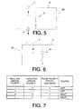
- This table which is shown in Figure 7 also includes the polarity of the partial discharge pulse, previously experimentally obtained from the polarity of the partial discharge in the inductive sensor and from the polarity of the partial discharge in the capacitive sensor.
- Figure 5 shows the layout of circuit equivalent to that depicted in Figure 1 for the case wherein the partial discharge pulse 20 has been produced to the right of the measuring point, so that in this case the pulse is positive, which determines that the polarity of the pulse detected in the inductive sensor 4 is positive and the polarity detected in the capacitive sensor is also positive, as shown in the table in Figure 7 , so that in this case the measurement device detects that the partial discharge pulse 20 comes from the right.
- Figure 6 shows the case wherein the partial discharge pulse 20 has negative polarity, In which case the polarity detected by the capacitive sensor is negative and the polarity detected by the inductive sensor is positive, which indicates that the partial discharge pulse 20 has been produced to the left of the measuring point.
- the other possible cases of partial discharge pulses that can be produced are not described as they are obvious to the person skilled in the art from the table shown in Figure 7 .
- the cables 2 from power lines also produce noise pulses that are generally coupled to the ground network and cable meshes 2, in which case the circumstance that one of the two capacitive 5 and inductive 4 sensors will not detect the noise pulse will occur, whereby the measurement device 18 knows that there has been an electric discharge when the two sensors detect the pulses, whereby noise pulses are differentiated from those generated by partial discharges.
- the time at which each detected pulse has reached the cell 1 makes it possible to locate the source of the discharge by comparing the data registered at each measurement device 18, whereby these are connected to means for comparing the data registered in each measurement device 18.
- a measurement device will detect that a pulse comes from the left and the other one comes from the right. With the time difference of the registers, assuming a given rate of propagation that is known, and checking the direction of the pulses on both measurement devices, the source 19 or partial discharge position 19 is determined.
- FIGS 8 and 9 show another possible embodiment of the invention that Is applied In electric machines 21 that are connected to a power line, so that it can determine that when a partial discharge occurs this comes from the electric machine or from the very line to which it is connected.
- the electric machines 21 can be motors, generators and transformers.
- the inductive sensors 4 are arranged around the cable 2 and in each of the phases of the power line are connected to measurement device 18.
- the capacitive sensor 5 consists of a capacitor and a resistor between which the socket for connecting to the measurement device 18 is made.
- the inductive sensor 4 is mounted around the cable 2 and is connected to a coaxial connector 24 that is supported on the sidewalls of the cable-gland device 22, so that said coaxial connector 24 constitutes the means for connecting the measurement device 18, thus making it possible to carry out the pulse sensing from outside the cable-gland device 22.
- the cable 2 is connected to a capacitor, which through a resistor is connected to the metal framework 22, which junction point of the capacitor and resistor is connected to a coaxial connector 24, just like to the previous one, which is also supported on the sidewalls of the cable-gland device22 in order to make it possible to allow the sensing by electrical coupling by means of a measurement device 18 connected to the coaxial connector 24.
Applications Claiming Priority (2)
| Application Number | Priority Date | Filing Date | Title |
|---|---|---|---|
| ES200930734A ES2365779B1 (es) | 2009-09-25 | 2009-09-25 | Sistema de medida de descargas parciales en líneas eléctricas. |
| PCT/ES2010/070614 WO2011036325A1 (es) | 2009-09-25 | 2010-09-23 | Sistema de medida de descargas parciales en líneas eléctricas |
Publications (1)
| Publication Number | Publication Date |
|---|---|
| EP2482090A1 true EP2482090A1 (de) | 2012-08-01 |
Family
ID=43795434
Family Applications (1)
| Application Number | Title | Priority Date | Filing Date |
|---|---|---|---|
| EP10818451A Withdrawn EP2482090A1 (de) | 2009-09-25 | 2010-09-23 | System zur messung partieller entladungen in stromleitungen |
Country Status (3)
| Country | Link |
|---|---|
| EP (1) | EP2482090A1 (de) |
| ES (1) | ES2365779B1 (de) |
| WO (1) | WO2011036325A1 (de) |
Cited By (2)
| Publication number | Priority date | Publication date | Assignee | Title |
|---|---|---|---|---|
| CN102981106A (zh) * | 2012-11-12 | 2013-03-20 | 华北电力大学 | 一种三相交叉互联电缆中间接头局部放电的在线检测方法 |
| NO20161993A1 (en) * | 2016-12-15 | 2018-04-09 | Wirescan As | Method for measuring an impedance of an electric cable, a coupler arrangement and uses thereof |
Families Citing this family (4)
| Publication number | Priority date | Publication date | Assignee | Title |
|---|---|---|---|---|
| RU2511607C1 (ru) * | 2012-10-01 | 2014-04-10 | Федеральное государственное бюджетное образовательное учреждение высшего профессионального образования "Владимирский государственный университет имени Александра Григорьевича и Николая Григорьевича Столетовых" (ВлГУ) | Способ электрошумовой диагностики высоковольтного оборудования |
| CN111766485A (zh) * | 2020-07-20 | 2020-10-13 | 国网新疆电力有限公司乌鲁木齐供电公司 | 用于电缆绝缘检测的电容传感器及其使用方法 |
| CN114113949A (zh) * | 2021-12-03 | 2022-03-01 | 广东电网有限责任公司广州供电局 | 一种测量局部放电的装置 |
| CN115166448B (zh) * | 2022-08-10 | 2023-04-07 | 特恩普电力科技(杭州)有限公司 | 一种开关柜局部放电监测装置 |
Family Cites Families (2)
| Publication number | Priority date | Publication date | Assignee | Title |
|---|---|---|---|---|
| EP0411863B1 (de) * | 1989-07-31 | 1995-12-20 | Mitsui Petrochemical Industries, Ltd. | Anordnung zur Überwachung der Isolationsverschlechterung einer elektrischen Installation |
| SE515387C2 (sv) * | 1995-05-02 | 2001-07-23 | Abb Research Ltd | Övervakning av interna partiella urladdningar i en krafttransformator |
-
2009
- 2009-09-25 ES ES200930734A patent/ES2365779B1/es active Active
-
2010
- 2010-09-23 WO PCT/ES2010/070614 patent/WO2011036325A1/es active Application Filing
- 2010-09-23 EP EP10818451A patent/EP2482090A1/de not_active Withdrawn
Non-Patent Citations (1)
| Title |
|---|
| See references of WO2011036325A1 * |
Cited By (7)
| Publication number | Priority date | Publication date | Assignee | Title |
|---|---|---|---|---|
| CN102981106A (zh) * | 2012-11-12 | 2013-03-20 | 华北电力大学 | 一种三相交叉互联电缆中间接头局部放电的在线检测方法 |
| CN102981106B (zh) * | 2012-11-12 | 2015-05-06 | 华北电力大学 | 一种三相交叉互联电缆中间接头局部放电的在线检测方法 |
| NO20161993A1 (en) * | 2016-12-15 | 2018-04-09 | Wirescan As | Method for measuring an impedance of an electric cable, a coupler arrangement and uses thereof |
| NO342173B1 (en) * | 2016-12-15 | 2018-04-09 | Wirescan As | Method for measuring an impedance of an electric cable, a coupler arrangement and uses thereof |
| WO2018111115A1 (en) * | 2016-12-15 | 2018-06-21 | Wirescan As | Method for measuring an impedance of an electric cable, a coupler arrangement and uses thereof |
| RU2765259C2 (ru) * | 2016-12-15 | 2022-01-27 | Уайрскан Ас | Способ измерения импеданса электрического кабеля, компоновка соединителя и их применение |
| US11280849B2 (en) | 2016-12-15 | 2022-03-22 | Wirescan As | Method for measuring an impedance of an electric cable, a coupler arrangement and uses thereof |
Also Published As
| Publication number | Publication date |
|---|---|
| ES2365779A1 (es) | 2011-10-11 |
| WO2011036325A1 (es) | 2011-03-31 |
| ES2365779B1 (es) | 2012-09-04 |
Similar Documents
| Publication | Publication Date | Title |
|---|---|---|
| EP2453247B1 (de) | Teilentladungskoppler zur Anwendung bei Hochspannungsgeneratorschienen | |
| CN103913679B (zh) | 高压开关柜局部放电在线监测系统 | |
| EP2482090A1 (de) | System zur messung partieller entladungen in stromleitungen | |
| CN103597365B (zh) | 部分放电产生的故障的定位设备和方法 | |
| Kumpulainen et al. | Pre-emptive arc fault detection techniques in switchgear and controlgear | |
| EP1252529B1 (de) | Prüfverbindung für teilentladungsdetektionen, teilentladungsdetektor- und verfahren zur erfassung von teilentladungen an einem stromkabel | |
| US9146268B2 (en) | Method and device for monitoring a sheath voltage arrester of a cable system | |
| CN102981106A (zh) | 一种三相交叉互联电缆中间接头局部放电的在线检测方法 | |
| CN103558523A (zh) | 一种开关柜局部放电检测装置 | |
| CN103558524A (zh) | 一种开关柜局部放电检测装置 | |
| CN104919324A (zh) | 天线与电缆的连接状态确认装置及确认方法 | |
| CN202583397U (zh) | 一种高压开关柜局部放电监测及定位系统 | |
| CN103713244B (zh) | 一种用于配电电缆局部放电的带电检测方法 | |
| CN106249054B (zh) | 电容式电压互感器及其一体化检测传感器 | |
| JP2015075482A (ja) | 部分放電検知プローブと携帯型部分放電測定器及び測定方法 | |
| CN204044215U (zh) | 一种用于局放检测及定位的多口高频脉冲电流互感器 | |
| JP2008191113A (ja) | ケーブル終端部の部分放電検出装置 | |
| CN106771843A (zh) | 一种单芯电力电缆的故障行波测距方法 | |
| CN114814465B (zh) | 一种配电线路故障查找系统及方法 | |
| CN101614582B (zh) | 一种提高旋转机械轴振动测量系统抗干扰能力的方法 | |
| Bergius | Implementation of on-line partial discharge measurements in medium voltage cable network | |
| JPH03128471A (ja) | 電気設備の絶縁劣化監視装置 | |
| CN210465583U (zh) | 一种用于海缆故障监测的传感器 | |
| CN1131278A (zh) | 用于耦合高压带电设备中的局部放电脉冲传感器 | |
| CN210664586U (zh) | 一种开关柜状态监测传感器组件 |
Legal Events
| Date | Code | Title | Description |
|---|---|---|---|
| PUAI | Public reference made under article 153(3) epc to a published international application that has entered the european phase |
Free format text: ORIGINAL CODE: 0009012 |
|
| 17P | Request for examination filed |
Effective date: 20110907 |
|
| AK | Designated contracting states |
Kind code of ref document: A1 Designated state(s): AL AT BE BG CH CY CZ DE DK EE ES FI FR GB GR HR HU IE IS IT LI LT LU LV MC MK MT NL NO PL PT RO SE SI SK SM TR |
|
| DAX | Request for extension of the european patent (deleted) | ||
| STAA | Information on the status of an ep patent application or granted ep patent |
Free format text: STATUS: THE APPLICATION IS DEEMED TO BE WITHDRAWN |
|
| 18D | Application deemed to be withdrawn |
Effective date: 20160401 |