EP2481588A1 - Liquid ejection apparatus and nonvolatile storage medium storing program - Google Patents
Liquid ejection apparatus and nonvolatile storage medium storing program Download PDFInfo
- Publication number
- EP2481588A1 EP2481588A1 EP12152831A EP12152831A EP2481588A1 EP 2481588 A1 EP2481588 A1 EP 2481588A1 EP 12152831 A EP12152831 A EP 12152831A EP 12152831 A EP12152831 A EP 12152831A EP 2481588 A1 EP2481588 A1 EP 2481588A1
- Authority
- EP
- European Patent Office
- Prior art keywords
- ejection
- humid
- liquid
- air
- space
- Prior art date
- Legal status (The legal status is an assumption and is not a legal conclusion. Google has not performed a legal analysis and makes no representation as to the accuracy of the status listed.)
- Granted
Links
Images




Classifications
-
- B—PERFORMING OPERATIONS; TRANSPORTING
- B41—PRINTING; LINING MACHINES; TYPEWRITERS; STAMPS
- B41J—TYPEWRITERS; SELECTIVE PRINTING MECHANISMS, i.e. MECHANISMS PRINTING OTHERWISE THAN FROM A FORME; CORRECTION OF TYPOGRAPHICAL ERRORS
- B41J2/00—Typewriters or selective printing mechanisms characterised by the printing or marking process for which they are designed
- B41J2/005—Typewriters or selective printing mechanisms characterised by the printing or marking process for which they are designed characterised by bringing liquid or particles selectively into contact with a printing material
- B41J2/01—Ink jet
- B41J2/135—Nozzles
- B41J2/165—Prevention or detection of nozzle clogging, e.g. cleaning, capping or moistening for nozzles
- B41J2/16517—Cleaning of print head nozzles
- B41J2/1652—Cleaning of print head nozzles by driving a fluid through the nozzles to the outside thereof, e.g. by applying pressure to the inside or vacuum at the outside of the print head
-
- B—PERFORMING OPERATIONS; TRANSPORTING
- B41—PRINTING; LINING MACHINES; TYPEWRITERS; STAMPS
- B41J—TYPEWRITERS; SELECTIVE PRINTING MECHANISMS, i.e. MECHANISMS PRINTING OTHERWISE THAN FROM A FORME; CORRECTION OF TYPOGRAPHICAL ERRORS
- B41J2/00—Typewriters or selective printing mechanisms characterised by the printing or marking process for which they are designed
- B41J2/005—Typewriters or selective printing mechanisms characterised by the printing or marking process for which they are designed characterised by bringing liquid or particles selectively into contact with a printing material
- B41J2/01—Ink jet
- B41J2/135—Nozzles
- B41J2/165—Prevention or detection of nozzle clogging, e.g. cleaning, capping or moistening for nozzles
-
- B—PERFORMING OPERATIONS; TRANSPORTING
- B41—PRINTING; LINING MACHINES; TYPEWRITERS; STAMPS
- B41J—TYPEWRITERS; SELECTIVE PRINTING MECHANISMS, i.e. MECHANISMS PRINTING OTHERWISE THAN FROM A FORME; CORRECTION OF TYPOGRAPHICAL ERRORS
- B41J2/00—Typewriters or selective printing mechanisms characterised by the printing or marking process for which they are designed
- B41J2/005—Typewriters or selective printing mechanisms characterised by the printing or marking process for which they are designed characterised by bringing liquid or particles selectively into contact with a printing material
- B41J2/01—Ink jet
- B41J2/135—Nozzles
- B41J2/165—Prevention or detection of nozzle clogging, e.g. cleaning, capping or moistening for nozzles
- B41J2/16505—Caps, spittoons or covers for cleaning or preventing drying out
- B41J2/16508—Caps, spittoons or covers for cleaning or preventing drying out connected with the printer frame
Definitions
- the present invention relates to a liquid ejection apparatus configured to eject liquid such as ink and to a nonvolatile storage medium storing a program to be executed by the liquid ejection apparatus.
- Patent Document 1 Japanese Patent Application Publication No. 2009-34912 discloses a fluid ejecting apparatus, as an ink-jet printer, configured to seal a space facing an ejection face of a head with a moisture-retention head cap when image recording is not performed, and configured to supply into the moisture-retention head cap water steam generated by a humidifier.
- a preliminary-ejection head cap into which ink is ejected is provided independently of the moisture-retention head cap, whereby the ink is not ejected into the moisture-retention head cap.
- Inventors of the present invention have found that, even if a moisture-retention head cap into which ink is not ejected is used, ink mist flying around a head and ink having unintentionally leaked from nozzles are accumulated in the moisture-retention head cap with passage of usage time of a recording apparatus, and this accumulated ink in the cap functions as a drying agent, thereby speeding up drying of the ink in the nozzles after the capping of the moisture-retention head cap.
- the supply of the water steam generated by the humidifier into the moisture-retention head cap may be not enough to humidify the ink in the nozzles. It is noted that this can be applied to the head cap functioning as both of the preliminary-ejection head cap and the moisture-retention head cap.
- This invention has been developed in view of the above-described situations, and it is an object of the present invention to provide a liquid ejection apparatus and a nonvolatile storage medium storing a program to be executed by the liquid ejection apparatus, capable of appropriately humidifying ejection openings even where liquid is accumulated in a cap.
- a liquid ejection apparatus comprising: a liquid-ejection head having an ejection face in which a plurality of ejection openings are formed, the liquid-ejection head being configured to eject liquid through the plurality of ejection openings to record an image on a recording medium; a sealing mechanism configured to selectively establish (i) a sealing state in which the sealing mechanism seals an ejection space in which the plurality of ejection openings are open, from an outside and (ii) an unsealing state in which the sealing mechanism does not seal the ejection space from the outside; a humid-air supply mechanism configured to supply a humid air into the ejection space when the sealing mechanism is in the sealing state; and a controller configured to control the humid-air supply mechanism such that an amount of the humid air to be supplied into the ejection space from the humid-air supply mechanism when the sealing mechanism is in the sealing state increases with a longer length of time of the unsealing state just before the current sealing
- the object indicated above may be achieved according to the present invention which provides a nonvolatile storage medium storing a program to be executed by a liquid ejection apparatus, the liquid ejection apparatus comprising: a liquid-ejection head having an ejection face in which a plurality of ejection openings are formed, the liquid-ejection head being configured to eject liquid through the plurality of ejection openings to record an image on a recording medium; a sealing mechanism configured to selectively establish (i) a sealing state in which the sealing mechanism seals an ejection space in which the plurality of ejection openings are open, from an outside and (ii) an unsealing state in which the sealing mechanism does not seal the ejection space from the outside; and a humid-air supply mechanism configured to supply a humid air into the ejection space, the program comprising: controlling the humid-air supply mechanism such that an amount of the humid air to be supplied into the ejection space from the humid-air supply mechanism when the sealing mechanism is in the sealing state increases with a longer
- the longer the length of time of the unsealing state just before the current sealing state the larger the amount of the humid air is which is to be supplied into the ejection space from the humid-air supply mechanism when the sealing mechanism is in the sealing state.
- a humidity in the ejection space can be adjusted to a relatively high humidity by the accumulated liquid, making it possible to appropriately humidify the ejection openings even where the liquid has been accumulated in the ejection space.
- the controller is configured to control the humid-air supply mechanism such that a humid-air supply period that is a length of time for which the humid air is supplied from the humid-air supply mechanism into the ejection space when the sealing mechanism is in the sealing state increases with the longer length of time of the unsealing state just before the current sealing state.
- the longer a humid-air supply period is which is a length of time for which the humid air is supplied from the humid-air supply mechanism into the ejection space when the sealing mechanism is in the sealing state.
- the controller is configured to determine the humid-air supply period in the current sealing state. Where the supply of the humid air has been stopped before the humid-air supply period in the current sealing state has not passed from a start of the supply of the humid air, the controller adds a time corresponding to a remaining time of the humid-air supply period in the current sealing state to a humid-air supply period.
- the liquid ejection apparatus comprises a humidity sensor configured to detect a humidity of an ambient air around the sealing mechanism.
- the controller is configured to determine the humid-air supply period on the basis of a result of the detection of the humidity sensor.
- the controller is configured to control the humid-air supply mechanism such that, after a first predetermined period has passed from a stop of the supply of the humid air into the ejection space in the current sealing state when the sealing mechanism is in the sealing state, the supply of the humid air into the ejection space is restarted in a next sealing state.
- the controller is configured to control the humid-air supply mechanism such that a density or a viscosity of the liquid in the plurality of ejection openings is made equal to or lower than a proper value by the supply of the humid air into the ejection space.
- the controller is configured to control the humid-air supply mechanism such that the humid-air supply period increases with a longer time elapsed from the last ejection of a liquid droplet from one of the plurality of ejection openings before the current sealing state is started.
- the controller is configured to further control the liquid-ejection head.
- the controller is configured to control the liquid-ejection head to eject a liquid droplet not contributing to the image recording from the plurality of ejection openings and then eject a liquid droplet contributing to the image recording from the plurality of ejection openings.
- the humidity of the ejection space, the density of the liquid near the ejection openings, a density of liquid other than the liquid near the ejection openings are brought into conditions of equilibrium.
- the density of the liquid near the ejection openings may become a relatively low density According to the construction as described above, only the liquid having the relatively low density is discharged, thereby preventing the lowering of the ejection characteristics.
- the sealing mechanism includes a cap member having a recessed portion formed therein. An opening end of the cap member contacts the ejection face to cause the sealing mechanism to establish the sealing state.
- the printer 1 includes a casing 1a having a rectangular parallelepiped shape.
- a sheet-discharge portion 31 is provided on a top plate of the casing 1a.
- An inner space of the casing 1a is divided into spaces A, B, and C in order from an upper side thereof.
- spaces A and B is formed a sheet conveyance path continuous to the sheet-discharge portion 31.
- ink cartridges 39 each as an ink supply source for ink-jet heads 10 each as an example of a liquid-ejection head.
- the space A there are arranged the four heads 10, a conveyance unit 21 for conveying a sheet P as an example of a recording medium, a guide unit for guiding the sheet P, a humidifying mechanism 50 (see Fig. 5 ) used for a humidifying maintenance, and so on.
- a controller 1p configured to control operations of components of the printer 1 to control an overall operation of the printer 1.
- the controller 1p controls: a conveyance operation of components of the printer 1 for conveying the sheet P; an ink ejecting operation synchronized with the conveyance of the sheet P; a maintenance operation for recovering or maintaining an ejection characteristic; and so on.
- the maintenance operation includes flushing, purging, wiping, humidifying maintenance, and so on.
- the flushing is an operation for forcibly ejecting ink from a part of or all of ejection openings 14a by driving actuators of the head 10 on the basis of flushing data that is different from the image data.
- the purging is an operation for forcibly ejecting the ink from all of the ejection openings 14a by applying a pressure to the ink in the head 10 by, e.g., a pump.
- the wiping is an operation for wiping foreign matters on ejection faces 10a by a wiper after the flushing or the purging.
- the humidifying maintenance is an operation for supplying humid air into ejection spaces (inner spaces) S1 (see Fig. 5 ) respectively facing the ejection faces 10a. It is noted that the humidifying maintenance will be explained in more detail later.
- the conveyance unit 21 includes (a) belt rollers 6, 7, (b) an endless conveyance belt 8 wound around the rollers 6, 7, (c) a nip roller 4 and a peeling plate 5 respectively disposed on opposite sides (outsides) of the conveyance belt 8, (d) a platen 9 disposed inside the conveyance belt 8, and so on.
- the belt roller 7 is a drive roller that is rotated in a clockwise direction in Fig. 1 by a conveyance motor, not shown.
- the conveyance belt 8 runs or is circulated along bold arrow in Fig. 1 in accordance with the rotation of the belt roller 7.
- the belt roller 6 is a driven roller that is rotated in the clockwise direction in Fig. 1 in accordance with the circulation of the conveyance belt 8.
- the nip roller 4 is disposed so as to face the belt roller 6 and press the sheet P supplied from an upstream side in a conveyance direction, onto a support face 8a of the conveyance belt 8 as an outer circumferential face thereof
- the sheet P is then conveyed toward the belt roller 7 in accordance with the circulation of the conveyance belt 8 while being supported on the support face 8a.
- the peeling plate 5 is disposed so as to face the belt roller 7, and peels the sheet P from the support face 8a and then guides the sheet P toward a downstream side in the conveyance direction.
- the platen 9 is disposed so as to face the four heads 10 and support an upper loop of the conveyance belt 8 from an inside thereof.
- Each of the heads 10 is a line head having a generally rectangular parallelepiped shape elongated in a main scanning direction in which each head 10 reciprocates.
- a lower face of each head 10 is the ejection face 10a having a multiplicity of the ejection openings 14a (see Figs. 3 and 4 ) opened therein.
- the four heads 10 eject inks of respective four colors, namely, magenta, cyan, yellow, and black from the respective ejection faces 10a.
- the four heads 10 are arranged in a sub-scanning direction at predetermined pitches and are supported by the casing 1a via a head holder 3.
- the head holder 3 supports the heads 10 such that the ejection faces 10a face the support face 8a of the upper loop of the conveyance belt 8 with a specific space therebetween for the recording operation.
- the circular caps 40 each for covering an outer region of the ejection face 10a of a corresponding one of the heads 10. Specific constructions of the heads 10 and the head holder 3 will be explained later.
- the guide unit includes an upstream guide portion and a downstream guide portion disposed with the conveyance unit 21 interposed therebetween.
- the upstream guide portion includes two guides 27a, 27b and a pair of conveyance rollers 26.
- the guide portion connects between a sheet-supply unit 1b (which will be described below) and the conveyance unit 21.
- the downstream guide portion includes two guides 29a, 29b and two pairs of conveyance rollers 28. This guide portion connects between the conveyance unit 21 and the sheet-discharge portion 31.
- the sheet-supply unit 1b In the space B is disposed the sheet-supply unit 1b that is mountable on and removable from the casing 1a.
- the sheet-supply unit 1b includes a sheet-supply tray 23 and a sheet-supply roller 25.
- the sheet-supply tray 23 has a box-like shape opening upward so as to accommodate various sizes of the sheet P.
- the sheet-supply roller 25 is rotated to supply an uppermost one of the sheets P in the sheet-supply tray 23 toward the upstream guide portion.
- the controller 1p drives a plurality of motors such as a sheet-supply motor, not shown, for the sheet-supply roller 25, a sheet-conveyance motor, not shown, for the conveyance rollers of each of the upstream and downstream guide portions, the above-described conveyance motor, and the like.
- the sheet P supplied from the sheet-supply tray 23 is supplied to the conveyance unit 21 by the conveyance rollers 26.
- the heads 10 When the sheet P passes through positions just under the heads 10 in the sub-scanning direction, the heads 10 eject the inks of the respective four colors in order from the respective ejection faces 10a, to record or form a color image on the sheet P.
- the ink ejection is performed on the basis of a detection signal outputted from a sheet sensor 32.
- the sheet P is then peeled by the peeling plate 5 and conveyed upward by the conveyance rollers 28.
- the sheet P is then discharged onto the sheet-discbarge portion 31 through an opening 30.
- the sub-scanning direction is a direction parallel to the conveyance direction in which the sheet P is conveyed by the conveyance unit 21, and the main scanning direction is a direction parallel to a horizontal plane and perpendicular to the sub-scanning direction.
- an ink unit 1c is disposed so as to be mountable on and removable from the casing 1a.
- the ink unit 1c includes a cartridge tray 35 and the four cartridges 39 accommodated in the tray 35 side by side.
- the inks stored in the respective cartridges 39 are to be supplied to the respective heads 10 via respective ink tubes, not shown.
- each head 10 there will be next explained the construction of each head 10 with reference to Figs. 2-4 and 7 in detail. It is noted that, in Fig. 3 , pressure chambers 16 and apertures 15 are illustrated by solid lines for easier understanding purposes though these elements are located under actuator units 17 and thus should be illustrated by broken lines. It is further noted that, since the four heads 10 have the same construction, the following explanation will be given for one of the heads 10 for the sake of simplicity.
- the head 10 includes a reservoir unit 11, a channel unit 12 (see Fig. 7 ), the eight actuator units 17 (see Fig. 2 ) fixed to an upper face 12x of the channel unit 12, a Flexible Printed Circuit (FPC) 19 (see Fig. 4 ) bonded to each of the actuator units 17 and so on which are stacked on one another in a vertical direction.
- the reservoir unit 11 are formed ink channels including a reservoir that temporarily stores the ink supplied from the cartridge 39 (see Fig. 1 ).
- In the channel unit 12 are formed ink channels each extending from a corresponding one of openings 12y of the upper face 12x (see Fig.
- the actuator units 17 include piezoelectric actuators for the respective ejection openings 14a.
- Protruding portions and recessed portions are formed on and in a lower face of the reservoir unit 11.
- the protruding portions are bonded to the upper face 12x of the channel unit 12 at areas on which no actuator units 17 are disposed (noted that the areas include the openings 12y and are enclosed with two-dot chain lines in Fig. 2 ).
- a distal end face of each of the protruding portions has an opening connected to the reservoir and facing a corresponding one of the openings 12y of the channel unit 12.
- the recessed portions face the upper face 12x of the channel unit 12, faces of the respective actuator units 17, and a face of the FPC 19 with slight spaces formed therebetween.
- the channel unit 12 is a stacked body constituted by nine metal rectangular plates 12a-12i (see Fig. 4 ) having generally the same size and bonded to one another.
- the channel unit 12 includes: manifold channels 13 each having a corresponding one of the openings 12y as one end; sub-manifold channels 13a each branched from a corresponding one of the manifold channels 13; the individual ink channels 14 respectively extending from outlets of the sub-manifold channels 13a to the ejection openings 14a via the pressure chambers 16.
- the individual channel 14 is formed for each ejection opening 14a so as to have the aperture 15 functioning as a restrictor for adjusting a channel resistance.
- rhombic openings for respectively exposing the pressure chambers 16 are formed in matrix in areas on the upper face 12x to which the actuator units 17 are respectively bonded.
- the ejection openings 14a are formed in matrix in the same pattern as the pressure chambers 16, in the lower face (i.e., the ejection face 10a) at areas opposed to the areas on the upper face 12x to which the actuator units 17 are respectively bonded.
- each of the actuator units 17 each having a trapezoid shape are arranged on the upper face 12x in two arrays in a staggered configuration.
- each of the actuator units 17 covers the multiplicity of the pressure chambers 16 formed under the actuator unit 17.
- each of the actuator units 17 includes: a plurality of piezoelectric layers expanding over the multiplicity of the pressure chambers 16; and electrodes interposing the piezoelectric layers in a thickness direction of the actuator units 17.
- the electrodes include: a common electrode common for the pressure chambers 16 and individual electrodes provided for the respective pressure chambers 16. The individual electrodes are formed on a face of an uppermost one of the piezoelectric layers.
- the FPC 19 has wirings corresponding to the respective electrodes of the actuator units 17, and a driver IC, not shown, is mounted on the wirings.
- the FPC 19 is fixed at one end thereof to the actuator units 17 and at the other end to a control board, not shown, of the head 10, which is disposed on an upper side of the reservoir unit 11. Under the control of the controller 1p (see Fig. 1 ), the FPC 19 sends the driver IC various drive signals outputted from the control board and sends the actuator units 17 signals produced by the driver IC.
- the head holder 3 is a frame made of a metal, for example.
- the cap 40 and a pair of joints 51 are mounted on the head holder 3.
- each pair of the joints 51 respectively constitute one and the other ends of the circulation channel of the humidifying mechanism 50 and are respectively disposed near one and the other ends of a corresponding one of the heads 10 in a longitudinal direction thereof.
- an air is sucked through an opening (outlet opening) 51a formed in a lower face of one of the pair of the joints 51 (the left joint 51 in Fig. 5 ), and a humid air is supplied through an opening (inlet opening) 51b formed in a lower face of the other of the pair of the joints 51.
- each of the joints 51 has a generally cylindrical shape and has a basal end portion 51x and a distal end portion 51y extending from the basal end portion 51x.
- a hollow space 51z is formed through the basal end portion 51x and the distal end portion 51y in the vertical direction.
- the basal end portion 51x and the distal end portion 51y have different outside diameters from each other, specifically, the basal end portion 51x has a greater outside diameter than that of the distal end portion 51y.
- the hollow space 51z has a uniform diameter along the vertical direction.
- the distal end portion 51y has a cutout in an outer face of an upper end thereof.
- a diameter of an upper end portion of the distal end portion 51y decreases from a lower side to an upper side thereof, that is, the upper end portion of the distal end portion 51y is tapered. This facilitates a connection of one end of a tube 55 or 57 to the distal end portion 51y.
- the joints 51 are fixed to the head holder 3 in a state in which the distal end portions 51y are inserted and fitted in respective through holes 3a of the head holder 3.
- the through holes 3a are formed at respective positions at which the joints 51 are disposed on the head holder 3, that is, the through holes 3a are respectively formed near one and the other ends of the head 10 in the longitudinal direction thereof.
- the outside diameter of the distal end portion 51y is one size smaller than that of the through hole 3 a.
- a small space is formed between an outer circumferential face of the distal end portion 51y and a wall face defining the through hole 3a of the head holder 3. This space is sealed by, e.g., a sealing material when the joint 51 is fixed to the head holder 3.
- Each cap 40 has a circular shape in plan view for enclosing an outer peripheral area of the ejection face 10a of the corresponding head 10.
- the cap 40 includes: an elastic member 41 supported by the head holder 3 via a fixed portion 41c, and a movable member 42 movable upward and downward.
- the elastic member 41 is formed of an elastic material such as a rubber and includes (a) a base portion 41x, (b) a projecting portion 41a projecting downward from a lower face of the base portion 41x so as to have an inverted triangle shape in cross section, (c) the fixed portion 41c having a T-shape in cross section and fixed to the head holder 3, and (e) a connecting portion 41d for connecting the base portion 41x and the fixed portion 41c to each other.
- the elastic member 41 has a circular shape in plan view for enclosing the outer peripheral area of the ejection face 10a. An upper end portion of the fixed portion 41c is fixed to the head holder 3 by adhesive, for example.
- the fixed portion 41c is sandwiched near the through hole 3a between the head holder 3 and the basal end portion 51x of the joint 51.
- the connecting portion 41d extends from a lower end of the fixed portion 41c and curves to an outside in a direction away from the ejection face 10a in plan view, so as to be connected to a lower end of the base portion 41x.
- the connecting portion 41d is deformable so as to be deformed according to the upward and downward movement of the movable member 42.
- An upper face of the base portion 41x has a recessed portion 41 b that is fitted on a lower end of the movable member 42.
- the movable member 42 is formed of a rigid material and has a circular shape in plan view for enclosing an outer peripheral area of the ejection face 10a of the head 10 like the elastic member 41.
- the movable member 42 is supported by the head holder 3 via the elastic member 41 so as to be movable relative to the head holder 3 in the vertical direction.
- the movable member 42 is connected to a plurality of gears 43 and moved upward and downward by the gears 43 rotated by a drive power outputted from an up-down motor 44 (see Fig. 8 ) under the control of the controller 1p.
- the base portion 41x is also moved upward and downward with the movable member 42 because the lower end of the movable member 42 is fitted in the recessed portion 41b of the elastic member 41,
- the projecting portion 41a is also moved upward and downward in the state in which the fixed portion 41c is fixed to the head holder 3.
- a position of a distal end 41al of the projecting portion 41a relative to the ejection face 10a in the vertical direction is changed.
- the projecting portion 41a is selectively positioned at a contact position (see Fig. 5 ) at which the distal end 41a1 is held in contact with the support face 8a of the conveyance belt 8 and at a distant position (see Fig. 6 ) at which the distal end 41a1 is distant from the support face 8a of the conveyance belt 8.
- a contact position at which the distal end 41a1 is held in contact with the support face 8a of the conveyance belt 8
- a distant position see Fig. 6
- a capping state airtight sealing state
- an uncapping state (unsealing state) is established in which the ejection space S1 communicates with the outside space S2.
- the ejection space S1 is a space facing the ejection face 10a, in other words, the ejection space S1 is the space in which the plurality of the ejection openings 14a formed in the ejection face 10a are opened, in other words, the ejection space S1 is the space to which the ink is ejected from the plurality of the ejection openings 14a.
- the caps 40 and the support faces 8a can be considered as examples of a sealing mechanism.
- the projecting portion 41a is distant from the ejection face 10a over an entire perimeter of the ejection face 10a (i.e., the lower face of the head 10 in Fig. 2 ) in plan view.
- the humidifying mechanism 50 as one example of a humid-air supply mechanism includes the joints 51, the tubes 55, 57, a tube 56, a pump 53, and a tank 54.
- the pair of the joints 51 are provided for each head 10, as shown in Fig. 7
- the single pump 53 and the single tank 54 are provided in the printer 1, that is, the single pump 53 and the single tank 54 are provided for the four heads 10 (see Fig. 7 ).
- the tube 55 includes a main portion 55a common for the four heads 10 and four branch portions 55b branched from the main portion 55a and each extending to a corresponding one of the joints 51.
- the tube 57 includes a main portion 57a common for the four heads 10 and four branch portions 57b branched from the main portion 57a and each extending to a corresponding one of the joints 51.
- One ends of the tube 55 are respectively fitted on the distal end portions 51y of the joints 51 (left joints 51 in Fig. 5 ) provided on the respective heads 10.
- the other end of the tube 55 is connected to the pump 53. That is, the tube 55 communicably connects the pump 53 and the hollow space 51z of one of each pair of the joints 51 to each other.
- the tube 56 communicably connects the pump 53 and the tank 54 to each other.
- One ends of the tube 57 (distal ends of the respective branch portions 57b) are respectively fitted on the distal end portions 51y of the joints 51 (right joints 51 in Fig. 5 ) provided on the respective heads 10.
- the other end of the tube 57 (an end of the main portion 57a opposite to the branch portions 57b) is connected to the tank 54. That is, the tube 57 communicably connects the tank 54 and the hollow space 51z of the other of each pair of the joints 51 to each other.
- the tank 54 stores water in its lower space and stores in its upper space the humid air humidified by the water stored in the lower space.
- the tube 56 is connected to a side face of the tank 54 below a water surface (i.e., an upper surface of the water), that is, the tube 56 is connected to the lower space of the tank 54.
- the tube 57 is connected to another side face of the tank 54 above the water surface, that is, the tube 57 communicates with the upper space of the tank 54.
- a check valve not shown, is provided on the tube 56 for preventing the water in the tank 54 from flowing into the pump 53, resulting in that the air flows only in a direction indicated by arrows in Fig. 5 .
- the controller 1p includes a Central Processing Unit (CPU); a nonvolatile memory for rewritably storing programs executed by the CPU and data used for these programs; and a Random Access Memory (RAM) for temporarily storing the date upon the execution of the program.
- the controller 1p includes various functional sections which are constituted by cooperation of these hardwares and softwares in the nonvolatile memory with each other. These programs are stored in various storage media such as a flexible disc, a CD-ROM, and a memory card, and installed from these storage medium into the nonvolatile memory. It is noted that control programs stored in the storage medium may be programs to be executed directly by the CPU and may be programs that become executable by being installed to the nonvolatile memory.
- control programs may be encrypted and/or compressed.
- the controller 1p includes an image-data storage section 61, a head controlling section 62, a capping-history storage section 63, a maintenance controlling section 64, and a conveyance controlling section 65.
- the image-data storage section 61 stores the image data based on which an image is recorded on the sheet P.
- the conveyance controlling section 65 is configured to control the conveyance unit 21 such that the sheet P is conveyed through the sheet conveyance path at a predetermined speed.
- the head controlling section 62 is configured to control the heads 10 such that the image is recorded on the sheet P conveyed by the conveyance unit 21 on the basis of the image data stored in the image-data storage section 61, and such that the flushing is performed in the maintenance operation.
- the capping-history storage section 63 stores therein a history of the uncapping state of each cap 40, a time corresponding to a remaining time of a supply time (which will be described below), an elapsed time elapsed from the last ejection of the ink from the ejection opening(s) 14a, and so on.
- the maintenance controlling section 64 is configured to control the pump 53 of the humidifying mechanism 50 and the up-down motor 44 for moving upward and downward the movable members 42 (the distal ends 41a1 of the respective projecting portions 41a) in order to perform the humidifying maintenance.
- the humidifying maintenance is an operation for humidifying the inside of each ejection space S1 in the state in which the cap 40 is in the capping state, and the humidifying maintenance is started after the image recording is completed. It is noted that the heads 10, the head holder 3, and the conveyance belt 8 are located at their respective predetermined positions during operations of the humidifying maintenance which will be described below.
- the head holder 3 is positioned while holding the heads 10 such that a predetermined space suitable for the recording is formed between the ejection faces 10a and the support face 8a.
- the maintenance controlling section 64 initially rotates the gears 43 to lower the movable member 42.
- the projecting portion 41a is located at the distant position (see Fig. 6 ) in the recording but moved to the contact position (see Fig. 5 ) by the downward movement of the movable member 42.
- the ejection space S1 is sealed to establish the capping state. It is noted that, in a standby state or a sleep (suspended) state other than the recording, the maintenance controlling section 64 moves the projecting portion 41a to the contact position to establish the capping state.
- the maintenance controlling section 64 includes a supply-time determining section 64a configured to determine a length of time for driving the pump 53 (i.e., the supply time for supplying the humid air into the ejection space S1) such that a density or a viscosity of the ink in the ejection openings 14a is equal to or lower than a proper value.
- the supply-time determining section 64a calculates the supply time such that the longer a length of time of a preceding (the last) uncapping state of the cap 40, which time is obtained by the capping history storage section 63, the longer the supply time in the current state is.
- the supply-time determining section 64a then corrects the obtained supply time such that, the longer the elapsed time elapsed from the last ejection of the ink from any of the ejection openings 14a, the longer the supply time in the current state is. Further, the supply-time determining section 64a corrects the obtained supply time such that the supply time is made longer, where a humidity detected by a humidity sensor 58 for detecting a humidity of an ambient air of the cap or caps 40 is equal to or lower than a predetermined value. It is noted that the proper value of the ink density is within a range in which a deterioration of the image is not caused when the image is formed on the sheet P by the ejection of the ink thereon, and this proper value is normally obtained by experiment.
- the proper value of the ink viscosity is within a range in which the ink is stably ejected from the heads 10 onto the sheet P, and this proper value is normally obtained by experiment.
- the humidity sensor 58 is for detecting the humidity of the ambient air of the caps 40 and disposed around the caps 40 in the outside space S2. It is noted that, since it can be considered that a humidity of the space in the casing 1a is generally the same at any positions in the space, the humidity sensor 58 can be disposed at any position in the casing 1a.
- the maintenance controlling section 64 then drives the pump 53 to suck the air in each ejection space S1 through the opening 51a of the corresponding joint 51, In this operation, the air sucked through the opening 51a is moved to the pump 53 through the hollow space 51z of the joint 51 and the tube 55 and then to the tank 54 through the tube 56.
- the air is supplied to the lower space of the tank 54 (on a lower side of the water surface).
- the air humidified by the water in the tank 54 (the humid air) is discharged from the upper space of the tank 54.
- the humidity of the humid air discharged from the upper space of the tank 54 is a value near 100%.
- the humidity of the humid air may be any value as long as the humidity is higher than the environmental humidity (i.e., a predetermined humidity that is the humidity of the outside space S2 around the caps 40).
- This humid air is supplied to the ejection space S1 from the opening 51b of the joint 51 through the tube 57.
- boldface arrows indicate the flow of the air before the humidification
- outline (white) arrows indicate the flow of the air after the humidification.
- the maintenance controlling section 64 controls switching valves, not shown, and so on provided on the branch portions 55b, 57b shown in Fig. 7 to selectively adjust the flows of the air in the branch portions 55b, 57b.
- the supply of the humid air from the opening 51b into the ejection space S1 increases humidity in the ejection space S1.
- the ink accumulated in the cap 40 is humidified, and the density and the viscosity of the ink in the ejection openings 14a are lowered.
- the maintenance controlling section 64 stops the driving of the pump 53 when the supply time obtained as described above has passed from the start of the driving of the pump 53. As a result, the humidifying maintenance is completed. It is noted that the humidity of the ejection space S1 lowers by, e.g., leaking of the humid air.
- the maintenance controlling section 64 drives the pump 53 again for a specific length of time to repeat the humidification of the ejection space S1.
- the first predetermined period is a predetermined length of time extending from the start of the capping state to a point in time when the supply of the humid air into the ejection space S1 is required again after the humidity of the ejection space S1 in the capping state lowers with the passage of time from the stop of the supply of the humid air.
- the maintenance controlling section 64 discontinues the humidifying maintenance and stops the driving of the pump 53 when having received the recording command before the supply time obtained as described above has passed from the start of the driving of the pump 53. Where a predetermined length of time (as one example of a second predetermined period) has not passed from the start of the driving of the pump 53 when the receiving command has been received, the maintenance controlling section 64 changes a state of the printer 1 to a recording state after flushing of the ink from the ejection openings 14a (ink ejection not contributing to or not related to the image forming) is performed.
- the maintenance controlling section 64 changes the state of the printer 1 to the recording state without the flushing. Thereafter, when the humidifying maintenance is started again after the image recording based on the recording command is completed, the supply-time determining section 64a adds, to the supply time obtained as described above, the time corresponding to the remaining time of the supply time. It is noted that the time corresponding to the remaining time of the supply time is the remaining time itself (a period obtained by subtracting, from the obtained supply time, a period from the start of the driving of the pump 53 to the stop of the driving of the pump 53) or a time obtained by multiplying the remaining time by a specific coefficient, for example.
- the second predetermined period is a length of time extending from the start of the driving of the pump 53 to a point in time when each of all of the humidity of the ejection space S1, a density of the ink near the ejection openings 14a, and a density of the ink other than the ink near the ejection openings 14a becomes the proper value of the ink density or the ink viscosity (in other words, when each of all of the humidity and densities becomes constant).
- the ink density of the ink near the ejection openings 14a is higher than the proper value (or the ink viscosity is higher than the proper value).
- flushing for discharging only the ink having a relatively high density or viscosity can prevent a lowering of ejection characteristics and the image deterioration.
- a reason why the time corresponding to the remaining time of the supply time is added to the obtained supply time is for the following reason, for example. That is, each of the ink viscosity and so on (including the ink density) in the ejection openings 14a is the proper value, but a viscosity and so on of the ink accumulated in the ejection space S1 is less than the proper value.
- the maintenance controlling section 64 changes the state of the cap 40 to the capping state to change the state of the printer 1 to a standby state after the completion of the image recording.
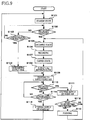
- the controller 1p in S103 judges whether or not a predetermined time has passed from a point in time when the cap 40 becomes the capping state.
- the controller 1p repeats the judgment in S102, Where the predetermined time has passed from the point in time when the cap 40 becomes the capping state (S103: YES), the maintenance controlling section 64 in S104 determines the supply time as the predetermined time and in S109 drives the pump 53 to start the supply of the humid air into the ejection space S1.
- the maintenance controlling section 64 in S105 changes the state of the cap 40 from the capping state to the uncapping state and the capping-history storage section 63 stores a time at which the uncapping state is started. Then in S106, the image recording is performed on the basis of the received recording command.
- the maintenance controlling section 64 in S107 starts the humidifying maintenance by changing the state of the cap 40 from the uncapping state to the capping state, and the capping-history storage section 63 stores a time at which the last uncapping state is finished.
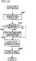
- the supply-time determining section 64a determines the supply time. As shown in Fig. 10 , in this determination, the supply-time determining section 64a in S201 calculates the supply time such that the longer the length of time of the preceding uncapping state of the cap 40, which time is obtained by the capping history storage section 63, the longer the supply time is.
- the supply-time determining section 64a judges whether the humidifying maintenance has been discontinued or not.
- the controller 1p in S203 adds the time corresponding to the remaining time of the supply time to the obtained supply time. Then in S204, the supply-time determining section 64a then corrects the obtained supply time such that, the longer the elapsed time elapsed from the last ejection of the ink from any of the ejection openings 14a, the longer the supply time is. Further, in S205, the supply-time determining section 64a corrects the obtained supply time such that the supply time is made longer, where the humidity detected by the humidity sensor 58 for detecting the humidity of the ambient air of the caps 40 is equal to or lower than the predetermined value.
- the maintenance controlling section 64 in S109 drives the pump 53 to supply the humid air into the ejection space S1. Then in S110, the maintenance controlling section 64 judges whether a new recording command has been received during the supply of the humid air or not. Where a new recording command has been received (S110: YES), the maintenance controlling section 64 in S111 stop the pump 53 to stop the supply of the humid air into the ejection space S1.
- the flushing of the ink from the ejection openings 14a is performed in S113, and then in S105 the state of the cap 40 is changed from the capping state to the uncapping state, and the above-described processings are repeated. Further, where the predetermined time (the second predetermined period) has passed from the start of the driving of the pump 53 (S112: NO) at the time when a new recording command has been received (S110: YES), the maintenance controlling section 64 executes the processings S105 and subsequent steps without flushing of the ink from the ejection openings 14a.
- the maintenance controlling section 64 in S114 judges whether the supply time obtained or determined as described above has passed from the start of the driving of the pump 53 or not. Where the supply time has not passed (S114: NO), the maintenance controlling section 64 in S110 judges again whether a new recording command has been received or not. Where the supply time has passed (S114: YES), the maintenance controlling section 64 in S115 stops the pump 53 to stop the supply of the humid air into the ejection space S1 and in S101 changes the state of the printer 1 to the standby state.
- the humidification of the ejection space S1 can be performed such that the ink density or the ink viscosity in the cap 40 becomes the proper value. That is, even where the ink is accumulated in the cap 40, the humidification can be performed into the ejection space S1 appropriately.
- the supply-time determining section 64a adds the time corresponding to the remaining time of the supply time when the humidifying maintenance has been discontinued, to the obtained supply time in the next humidifying maintenance. As a result, even where the ink is accumulated in the cap 40, the humidification of the ejection openings 14a can be reliably performed.
- the supply-time determining section 64a makes the supply time longer where the humidity detected by the humidity sensor 58 for detecting the humidity of the ambient air of the caps 40 is equal to or lower than the predetermined value, it is possible to accurately adjust the humidity of the ejection space S1.
- the ejection space S1 is humidified again.
- the cap 40 is in the capping state, the lowering of the humidity of the ejection space S1 with the passage of time can be prevented, making it possible to prevent the increase in the ink viscosity or the ink density in the ejection openings 14a.
- the supply time for supplying the humid air into the ejection space S1 is determined such that the density or the viscosity of the ink in the ejection openings 14a is equal to or lower than the proper value, it is possible to prevent the lowering of the ink ejection characteristics due to increased viscosity of the ink in the ejection openings 14a by the drying.
- the supply time is determined such that, the longer the elapsed time elapsed from the last ejection of the ink from any of the ejection openings 14a, the longer the supply time is made.
- the drying it is possible to prevent the lowering of the ink ejection characteristics due to the increased viscosity of the ink in the ejection openings 14a by the drying.
- the state of the printer 1 is changed to the recording state after the humidifying maintenance is discontinued and the flushing of the ink from the ejection openings 14a is performed.
- the recording command has been received before the predetermined time shorter than the obtained supply time has passed from the start of the driving of the pump 53
- the state of the printer 1 is changed to the recording state after the humidifying maintenance is discontinued and the flushing of the ink from the ejection openings 14a is performed.
- the air sucked through the opening 51a is moved to the pump 53 through the hollow space 51z of the joint 51 and the tube 55 and then to the tank 54 through the tube 56.
- the air is then moved through the tube 57 and supplied from the opening 51b into the ejection space S1. Since this circulation allows reuse of the humid air, the humid air can be speedily supplied. Further, the humid air can be supplied in the state in which the ejection space S1 is sealed.
- the distal end 41a1 is selectively positioned at the contact position at which the distal end 41a1 is held in contact with the support face 8a of the conveyance belt 8 and at the distant position at which the distal end 41a1 is distant from the support face 8a of the conveyance belt 8.
- the ejection spaces S1 can be reliably sealed by a simple construction. Further, it is possible to speedily change the capping state and the uncapping state to each other.
- the time (period) of the supply of the humid air is adjusted in, e.g., S201, but an amount of the humid air to be supplied from the humidifying mechanism 50 into the ejection space S1 may be adjusted on the basis of, e.g., a time (period) of a preceding uncapping state.
- the amount of the humid air to be supplied from the humidifying mechanism 50 into the ejection space S1 may be increased with the longer preceding uncapping state.
- a remaining amount of the supply amount (an amount obtained by subtracting, from a supply amount determined in advance, an amount of the humid air supplied in the period from the start of the driving of the pump 53 to the stop of the driving of the pump 53) in the last humidification may be added to a humid-air supply amount in a current humidification.
- the supply amount of the humid air in the current humidification may be increased with the longer elapsed time elapsed from the last ink ejection before the current humidification.
- the supply amount of the humid air may be corrected to be made larger.
- the amount of the humid air to be supplied from the humidifying mechanism 50 into the ejection space S1 can be increased by lengthening the time for supplying the humid air as in the above-described embodiment or by increasing an amount of the humid air discharged per unit time by the pump 53 of the humidifying mechanism 50. In the latter case, the supply amount of the humid air can be increased without lengthening the supply time of the humid air. It is noted that the supply amount of the humid air may be increased by lengthening the time for supplying the humid air and increasing the amount of the humid air discharged per unit time by the pump 53.
- the supply-time determining section 64a adds the time corresponding to the remaining time of the supply time when the humidifying maintenance has been discontinued, to the obtained supply time in the next humidifying maintenance, but the time corresponding to the remaining time may not be added to the obtained supply time.
- the supply-time determining section 64a calculates the supply time such that, the longer the length of time of the preceding uncapping state of the cap 40, which time is obtained by the capping history storage section 63, the longer the supply time is, but in addition to this, the supply-time determining section 64a may calculate the supply time such that, the longer a length of time from the establishment of the capping state to the start of the supply of the humid air, the longer the supply time is. This is because the drying of the ink in the ejection openings 14a continues also after the capping state is established (noted that a speed of the drying is slower than in the uncapping state).
- the supply-time determining section 64a makes the supply time longer where the humidity detected by the humidity sensor 58 for detecting the humidity of the ambient air of the caps 40 is equal to or lower than the predetermined value, but the supply time may be determined without considering the humidity of the ambient air of the caps 40.
- the printer 1 may be configured such that the printer 1 includes a temperature sensor for detecting a temperature of the ambient air of the caps 40, and the supply-time determining section 64a determines the supply time such that the supply time is made longer where a temperature detected by the temperature sensor is equal to or higher than a predetermined value.
- the ejection space S1 is humidified again, but such a humidification may not be performed.
- the supply time for supplying the humid air into the ejection space S1 is determined such that the density or the viscosity of the ink in the ejection openings 14a is equal to or lower than the proper value, but where the humidity in the ejection space S1 is higher than the environmental humidity, the density or the viscosity of the ink in the ejection openings 14a may be equal to or higher than the proper value.
- the supply of the humid air makes it possible to reduce an amount of the ink to be discharged.
- this printer 1 may be configured such that the flushing is performed each time when the humidifying maintenance is discontinued.
- the humid air is reused by the circulation in the humidifying maintenance but may be discharged to the outside of the ejection space S1 without the circulation of the humid air.
- the projecting portion 41a is not limited to be movable as in the above-described embodiment.
- the printer 1 may be configured such that the projecting portions are fixed to the head holder so as not to be movable, and positions of the distal ends of the respective projecting portions relative to the ejection face are constant.
- the positions of the distal ends of the respective projecting portions relative to the ejection face can be changed by raising and lowering the head holder or the support face of the conveyance belt, whereby the projecting portions can be selectively positioned at the contact position and the distant position.
- a cap 240 as one example of a cap member may be formed independently of the head 10.
- the cap 240 is disposed at a position facing the ejection face 10a by a cap moving mechanism, not shown.
- the cap 240 can be selectively positioned at a contact position at which an end portion 241a (as one example of an opening end) of the cap 240 is held in contact with the ejection face 10a and a distant position at which the end portion 241a is distant from the ejection face 10a by raising or lowering at least one of the head 10 and the cap 240.
- an ejection space S201 is sealed with the cap 240 (a capping state).
- the ejection space S201 is not sealed (an uncapping state).
- the inlet opening and the outlet opening of the circulation channel are formed in the head holder, but the inlet opening and the outlet opening may be formed in the head, the head holder, or the cap. Where the inlet opening and the outlet opening are formed in the cap, the humidifying mechanism 50 may be provided near the caps (noted that, in Fig. 5 , the humidifying mechanism 50 is provided near the heads 10).
- the pump 53 and the tank 54 are used as the humidifying mechanism in the above-described embodiment, but other components or mechanism may be used as long as the air in the circulation channel can be humidified.
- the printer 1 may be configured such that the humidification is performed only by the tank 54 without providing the pump 53.
- the humidification may be performed by further using a heating means such as a heater, by using an ultrasound humidifying means, or by disposing a wet porous material such as a wet sponge or a wet cloth in the circulation channel.
- the present invention is applicable to any of a line printer and a serial printer. Further, the application of the present invention is not limited to the printer, and the present invention is also applicable to devices such as a facsimile machine and a copying machine. Further, the present invention is also applicable to a device configured to eject liquid other than the ink.
Landscapes
- Ink Jet (AREA)
Abstract
Description
- The present invention relates to a liquid ejection apparatus configured to eject liquid such as ink and to a nonvolatile storage medium storing a program to be executed by the liquid ejection apparatus.
- Patent Document 1 (Japanese Patent Application Publication No.
2009-34912 - Inventors of the present invention have found that, even if a moisture-retention head cap into which ink is not ejected is used, ink mist flying around a head and ink having unintentionally leaked from nozzles are accumulated in the moisture-retention head cap with passage of usage time of a recording apparatus, and this accumulated ink in the cap functions as a drying agent, thereby speeding up drying of the ink in the nozzles after the capping of the moisture-retention head cap. In this case, merely the supply of the water steam generated by the humidifier into the moisture-retention head cap may be not enough to humidify the ink in the nozzles. It is noted that this can be applied to the head cap functioning as both of the preliminary-ejection head cap and the moisture-retention head cap.
- This invention has been developed in view of the above-described situations, and it is an object of the present invention to provide a liquid ejection apparatus and a nonvolatile storage medium storing a program to be executed by the liquid ejection apparatus, capable of appropriately humidifying ejection openings even where liquid is accumulated in a cap.
- The object indicated above may be achieved according to the present invention which provides a liquid ejection apparatus, comprising: a liquid-ejection head having an ejection face in which a plurality of ejection openings are formed, the liquid-ejection head being configured to eject liquid through the plurality of ejection openings to record an image on a recording medium; a sealing mechanism configured to selectively establish (i) a sealing state in which the sealing mechanism seals an ejection space in which the plurality of ejection openings are open, from an outside and (ii) an unsealing state in which the sealing mechanism does not seal the ejection space from the outside; a humid-air supply mechanism configured to supply a humid air into the ejection space when the sealing mechanism is in the sealing state; and a controller configured to control the humid-air supply mechanism such that an amount of the humid air to be supplied into the ejection space from the humid-air supply mechanism when the sealing mechanism is in the sealing state increases with a longer length of time of the unsealing state just before the current sealing state.
- The object indicated above may be achieved according to the present invention which provides a nonvolatile storage medium storing a program to be executed by a liquid ejection apparatus, the liquid ejection apparatus comprising: a liquid-ejection head having an ejection face in which a plurality of ejection openings are formed, the liquid-ejection head being configured to eject liquid through the plurality of ejection openings to record an image on a recording medium; a sealing mechanism configured to selectively establish (i) a sealing state in which the sealing mechanism seals an ejection space in which the plurality of ejection openings are open, from an outside and (ii) an unsealing state in which the sealing mechanism does not seal the ejection space from the outside; and a humid-air supply mechanism configured to supply a humid air into the ejection space, the program comprising: controlling the humid-air supply mechanism such that an amount of the humid air to be supplied into the ejection space from the humid-air supply mechanism when the sealing mechanism is in the sealing state increases with a longer length of time of the unsealing state just before the current sealing state.
- In the liquid ejection apparatus constructed as described above and the program to be executed by the liquid ejection apparatus, the longer the length of time of the unsealing state just before the current sealing state, the larger the amount of the humid air is which is to be supplied into the ejection space from the humid-air supply mechanism when the sealing mechanism is in the sealing state. Thus, even where water (moisture) of the air supplied into the ejection space is sucked into liquid accumulated in the ejection space, a humidity in the ejection space can be adjusted to a relatively high humidity by the accumulated liquid, making it possible to appropriately humidify the ejection openings even where the liquid has been accumulated in the ejection space.
- In the liquid ejection apparatus, the controller is configured to control the humid-air supply mechanism such that a humid-air supply period that is a length of time for which the humid air is supplied from the humid-air supply mechanism into the ejection space when the sealing mechanism is in the sealing state increases with the longer length of time of the unsealing state just before the current sealing state.
- According to the construction as described above, the longer the length of time of the unsealing state just before the current sealing state, the longer a humid-air supply period is which is a length of time for which the humid air is supplied from the humid-air supply mechanism into the ejection space when the sealing mechanism is in the sealing state. Thus, even where the water (moisture) of the air supplied into the ejection space is sucked into the liquid accumulated in the ejection space by the accumulated liquid, the humidity in the ejection space can be adjusted to the relatively high humidity, making it possible to appropriately humidify the ejection openings even where the liquid has been accumulated in the ejection space.
- In the liquid ejection apparatus, the controller is configured to determine the humid-air supply period in the current sealing state. Where the supply of the humid air has been stopped before the humid-air supply period in the current sealing state has not passed from a start of the supply of the humid air, the controller adds a time corresponding to a remaining time of the humid-air supply period in the current sealing state to a humid-air supply period.
- According to the construction as described above, even if the liquid is accumulated in the ejection space, the humidification of the ejection openings can be reliably performed.
- The liquid ejection apparatus comprises a humidity sensor configured to detect a humidity of an ambient air around the sealing mechanism. The controller is configured to determine the humid-air supply period on the basis of a result of the detection of the humidity sensor.
- According to the construction as described above, it is possible to accurately adjust the humidity in the ejection space.
- In the liquid ejection apparatus, the controller is configured to control the humid-air supply mechanism such that, after a first predetermined period has passed from a stop of the supply of the humid air into the ejection space in the current sealing state when the sealing mechanism is in the sealing state, the supply of the humid air into the ejection space is restarted in a next sealing state.
- According to the construction as described above, even where the sealing mechanism is in the sealing state, a lowering of the humidity in the ejection space with the passage of time can be prevented, making it possible to prevent an increase in a viscosity or a density of the liquid in the ejection openings.
- In the liquid ejection apparatus, the controller is configured to control the humid-air supply mechanism such that a density or a viscosity of the liquid in the plurality of ejection openings is made equal to or lower than a proper value by the supply of the humid air into the ejection space.
- According to the construction as described above, it is possible to prevent a lowering of ejection characteristics due to increased viscosity of the liquid in the ejection openings by drying.
- In the liquid ejection apparatus, the controller is configured to control the humid-air supply mechanism such that the humid-air supply period increases with a longer time elapsed from the last ejection of a liquid droplet from one of the plurality of ejection openings before the current sealing state is started.
- According to the construction as described above, it is possible to prevent the lowering of the ejection characteristics due to the increased viscosity of the liquid in the ejection openings by drying.
- In the liquid ejection apparatus, the controller is configured to further control the liquid-ejection head. Where the supply of the humid air into the ejection space by the humid-air supply mechanism is stopped to start the image recording before a second predetermined period has passed from a start of the supply of the humid air into the ejection space, the controller is configured to control the liquid-ejection head to eject a liquid droplet not contributing to the image recording from the plurality of ejection openings and then eject a liquid droplet contributing to the image recording from the plurality of ejection openings.
- It requires a relatively long time (a second predetermined period) that the humidity of the ejection space, the density of the liquid near the ejection openings, a density of liquid other than the liquid near the ejection openings are brought into conditions of equilibrium. Where the supply of the air is stopped before the second predetermined period has passed, the density of the liquid near the ejection openings may become a relatively low density According to the construction as described above, only the liquid having the relatively low density is discharged, thereby preventing the lowering of the ejection characteristics.
- In the liquid ejection apparatus, the sealing mechanism includes a cap member having a recessed portion formed therein. An opening end of the cap member contacts the ejection face to cause the sealing mechanism to establish the sealing state.
- According to the construction as described above, it is possible to seal the ejection space with a simple construction.
- The objects, features, advantages, and technical and industrial significance of the present invention will be better understood by reading the following detailed description of an embodiment of the invention, when considered in connection with the accompanying drawings, in which:
-
Fig. 1 is a side view generally showing an internal structure of an ink-jet printer as an embodiment of the present invention; -
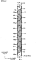
Fig. 2 is a plan view showing a channel unit and actuator units of each ink-jet head of the printer inFig. 1 ; -
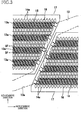
Fig. 3 is an enlarged view showing an area III enclosed by one-dot chain line inFig. 2 ; -
Fig. 4 is a partial cross-sectional view taken along line IV-IV inFig. 3 ; -
Fig. 5 is a schematic view showing a head holder and a humidifying mechanism of the printer inFig. 1 ; -
Fig. 6 is a partial cross-sectional view showing an area VI enclosed with a one-dot chain line inFig. 5 ; -
Fig. 7 is a schematic view showing connection between all the heads of the printer inFig. 1 and a humidifying mechanism; -
Fig. 8 is a block diagram showing functions of a controller of the printer inFig. 1 ; -
Fig. 9 is a flow-chart showing a recording operation of the printer inFig. 1 ; -
Fig. 10 is a flow-chart showing a supply time determination inFig. 9 ; and -
Fig. 11 is a view for explaining a modification of the embodiment of the present invention. - Hereinafter, there will be described an embodiment of the present invention by reference to the drawings.
- First, there will be explained an overall construction of an ink-
jet printer 1 as an embodiment of the present invention. - As shown in
Fig. 1 , theprinter 1 includes acasing 1a having a rectangular parallelepiped shape. A sheet-discharge portion 31 is provided on a top plate of thecasing 1a. An inner space of thecasing 1a is divided into spaces A, B, and C in order from an upper side thereof. In the spaces A and B is formed a sheet conveyance path continuous to the sheet-discharge portion 31. In the space C are accommodatedink cartridges 39 each as an ink supply source for ink-jet heads 10 each as an example of a liquid-ejection head. - In the space A, there are arranged the four
heads 10, aconveyance unit 21 for conveying a sheet P as an example of a recording medium, a guide unit for guiding the sheet P, a humidifying mechanism 50 (seeFig. 5 ) used for a humidifying maintenance, and so on. In an upper portion of the space A, there is disposed acontroller 1p configured to control operations of components of theprinter 1 to control an overall operation of theprinter 1. - On the basis of image data transmitted from an external device, the
controller 1p controls: a conveyance operation of components of theprinter 1 for conveying the sheet P; an ink ejecting operation synchronized with the conveyance of the sheet P; a maintenance operation for recovering or maintaining an ejection characteristic; and so on. The maintenance operation includes flushing, purging, wiping, humidifying maintenance, and so on. The flushing is an operation for forcibly ejecting ink from a part of or all ofejection openings 14a by driving actuators of thehead 10 on the basis of flushing data that is different from the image data. The purging is an operation for forcibly ejecting the ink from all of theejection openings 14a by applying a pressure to the ink in thehead 10 by, e.g., a pump. The wiping is an operation for wiping foreign matters on ejection faces 10a by a wiper after the flushing or the purging. The humidifying maintenance is an operation for supplying humid air into ejection spaces (inner spaces) S1 (seeFig. 5 ) respectively facing the ejection faces 10a. It is noted that the humidifying maintenance will be explained in more detail later. - The
conveyance unit 21 includes (a)belt rollers endless conveyance belt 8 wound around therollers roller 4 and apeeling plate 5 respectively disposed on opposite sides (outsides) of theconveyance belt 8, (d) a platen 9 disposed inside theconveyance belt 8, and so on. Thebelt roller 7 is a drive roller that is rotated in a clockwise direction inFig. 1 by a conveyance motor, not shown. Theconveyance belt 8 runs or is circulated along bold arrow inFig. 1 in accordance with the rotation of thebelt roller 7. Thebelt roller 6 is a driven roller that is rotated in the clockwise direction inFig. 1 in accordance with the circulation of theconveyance belt 8. Thenip roller 4 is disposed so as to face thebelt roller 6 and press the sheet P supplied from an upstream side in a conveyance direction, onto asupport face 8a of theconveyance belt 8 as an outer circumferential face thereof The sheet P is then conveyed toward thebelt roller 7 in accordance with the circulation of theconveyance belt 8 while being supported on thesupport face 8a. The peelingplate 5 is disposed so as to face thebelt roller 7, and peels the sheet P from thesupport face 8a and then guides the sheet P toward a downstream side in the conveyance direction. The platen 9 is disposed so as to face the fourheads 10 and support an upper loop of theconveyance belt 8 from an inside thereof. - Each of the
heads 10 is a line head having a generally rectangular parallelepiped shape elongated in a main scanning direction in which eachhead 10 reciprocates. A lower face of eachhead 10 is theejection face 10a having a multiplicity of theejection openings 14a (seeFigs. 3 and4 ) opened therein. In a recording operation, the fourheads 10 eject inks of respective four colors, namely, magenta, cyan, yellow, and black from the respective ejection faces 10a. The four heads 10 are arranged in a sub-scanning direction at predetermined pitches and are supported by thecasing 1a via ahead holder 3. Thehead holder 3 supports theheads 10 such that the ejection faces 10a face thesupport face 8a of the upper loop of theconveyance belt 8 with a specific space therebetween for the recording operation. On thehead holder 3 are provided thecircular caps 40 each for covering an outer region of theejection face 10a of a corresponding one of theheads 10. Specific constructions of theheads 10 and thehead holder 3 will be explained later. - The guide unit includes an upstream guide portion and a downstream guide portion disposed with the
conveyance unit 21 interposed therebetween. The upstream guide portion includes twoguides conveyance rollers 26. The guide portion connects between a sheet-supply unit 1b (which will be described below) and theconveyance unit 21. The downstream guide portion includes twoguides conveyance rollers 28. This guide portion connects between theconveyance unit 21 and the sheet-discharge portion 31. - In the space B is disposed the sheet-
supply unit 1b that is mountable on and removable from thecasing 1a. The sheet-supply unit 1b includes a sheet-supply tray 23 and a sheet-supply roller 25. The sheet-supply tray 23 has a box-like shape opening upward so as to accommodate various sizes of the sheet P. The sheet-supply roller 25 is rotated to supply an uppermost one of the sheets P in the sheet-supply tray 23 toward the upstream guide portion. - As described above, in the spaces A, B is formed the sheet conveyance path extending from the sheet-
supply unit 1b to the sheet-discharge portion 31 via theconveyance unit 21. On the basis of a recording command transmitted from the external device, thecontroller 1p drives a plurality of motors such as a sheet-supply motor, not shown, for the sheet-supply roller 25, a sheet-conveyance motor, not shown, for the conveyance rollers of each of the upstream and downstream guide portions, the above-described conveyance motor, and the like. The sheet P supplied from the sheet-supply tray 23 is supplied to theconveyance unit 21 by theconveyance rollers 26. When the sheet P passes through positions just under theheads 10 in the sub-scanning direction, theheads 10 eject the inks of the respective four colors in order from the respective ejection faces 10a, to record or form a color image on the sheet P. The ink ejection is performed on the basis of a detection signal outputted from asheet sensor 32. The sheet P is then peeled by the peelingplate 5 and conveyed upward by theconveyance rollers 28. The sheet P is then discharged onto the sheet-discbarge portion 31 through anopening 30. - Here, the sub-scanning direction is a direction parallel to the conveyance direction in which the sheet P is conveyed by the
conveyance unit 21, and the main scanning direction is a direction parallel to a horizontal plane and perpendicular to the sub-scanning direction. - In the space C, an
ink unit 1c is disposed so as to be mountable on and removable from thecasing 1a. Theink unit 1c includes acartridge tray 35 and the fourcartridges 39 accommodated in thetray 35 side by side. The inks stored in therespective cartridges 39 are to be supplied to therespective heads 10 via respective ink tubes, not shown. - There will be next explained the construction of each
head 10 with reference toFigs. 2-4 and7 in detail. It is noted that, inFig. 3 ,pressure chambers 16 andapertures 15 are illustrated by solid lines for easier understanding purposes though these elements are located underactuator units 17 and thus should be illustrated by broken lines. It is further noted that, since the fourheads 10 have the same construction, the following explanation will be given for one of theheads 10 for the sake of simplicity. - The
head 10 includes a reservoir unit 11, a channel unit 12 (seeFig. 7 ), the eight actuator units 17 (seeFig. 2 ) fixed to anupper face 12x of thechannel unit 12, a Flexible Printed Circuit (FPC) 19 (seeFig. 4 ) bonded to each of theactuator units 17 and so on which are stacked on one another in a vertical direction. In the reservoir unit 11 are formed ink channels including a reservoir that temporarily stores the ink supplied from the cartridge 39 (seeFig. 1 ). In thechannel unit 12 are formed ink channels each extending from a corresponding one ofopenings 12y of theupper face 12x (seeFig. 2 ) of thechannel unit 12 to a corresponding one of theejection openings 14a formed in a lower face of the channel unit 12 (i.e., theejection face 10a). Theactuator units 17 include piezoelectric actuators for therespective ejection openings 14a. - Protruding portions and recessed portions are formed on and in a lower face of the reservoir unit 11. The protruding portions are bonded to the
upper face 12x of thechannel unit 12 at areas on which noactuator units 17 are disposed (noted that the areas include theopenings 12y and are enclosed with two-dot chain lines inFig. 2 ). A distal end face of each of the protruding portions has an opening connected to the reservoir and facing a corresponding one of theopenings 12y of thechannel unit 12. As a result, the reservoir andindividual ink channels 14 are communicated with each other via the above-described openings. The recessed portions face theupper face 12x of thechannel unit 12, faces of therespective actuator units 17, and a face of theFPC 19 with slight spaces formed therebetween. - The
channel unit 12 is a stacked body constituted by nine metalrectangular plates 12a-12i (seeFig. 4 ) having generally the same size and bonded to one another. As shown inFigs. 2-4 , thechannel unit 12 includes:manifold channels 13 each having a corresponding one of theopenings 12y as one end;sub-manifold channels 13a each branched from a corresponding one of themanifold channels 13; theindividual ink channels 14 respectively extending from outlets of thesub-manifold channels 13a to theejection openings 14a via thepressure chambers 16. As shown inFig. 4 , theindividual channel 14 is formed for each ejection opening 14a so as to have theaperture 15 functioning as a restrictor for adjusting a channel resistance. Generally rhombic openings for respectively exposing thepressure chambers 16 are formed in matrix in areas on theupper face 12x to which theactuator units 17 are respectively bonded. Theejection openings 14a are formed in matrix in the same pattern as thepressure chambers 16, in the lower face (i.e., theejection face 10a) at areas opposed to the areas on theupper face 12x to which theactuator units 17 are respectively bonded. - As shown in
Fig. 2 , theactuator units 17 each having a trapezoid shape are arranged on theupper face 12x in two arrays in a staggered configuration. As shown inFig. 3 , each of theactuator units 17 covers the multiplicity of thepressure chambers 16 formed under theactuator unit 17. Though not shown, each of theactuator units 17 includes: a plurality of piezoelectric layers expanding over the multiplicity of thepressure chambers 16; and electrodes interposing the piezoelectric layers in a thickness direction of theactuator units 17. The electrodes include: a common electrode common for thepressure chambers 16 and individual electrodes provided for therespective pressure chambers 16. The individual electrodes are formed on a face of an uppermost one of the piezoelectric layers. - The
FPC 19 has wirings corresponding to the respective electrodes of theactuator units 17, and a driver IC, not shown, is mounted on the wirings. TheFPC 19 is fixed at one end thereof to theactuator units 17 and at the other end to a control board, not shown, of thehead 10, which is disposed on an upper side of the reservoir unit 11. Under the control of thecontroller 1p (seeFig. 1 ), theFPC 19 sends the driver IC various drive signals outputted from the control board and sends theactuator units 17 signals produced by the driver IC. - There will be next explained a construction of the
head holder 3 with reference toFigs. 2 ,5 , and6 . - The
head holder 3 is a frame made of a metal, for example. For eachhead 10, thecap 40 and a pair ofjoints 51 are mounted on thehead holder 3. - As shown in
Fig. 5 , each pair of thejoints 51 respectively constitute one and the other ends of the circulation channel of thehumidifying mechanism 50 and are respectively disposed near one and the other ends of a corresponding one of theheads 10 in a longitudinal direction thereof. In the humidifying maintenance, an air is sucked through an opening (outlet opening) 51a formed in a lower face of one of the pair of the joints 51 (the left joint 51 inFig. 5 ), and a humid air is supplied through an opening (inlet opening) 51b formed in a lower face of the other of the pair of thejoints 51. - As shown in
Fig. 6 , each of thejoints 51 has a generally cylindrical shape and has a basal end portion 51x and a distal end portion 51y extending from the basal end portion 51x. Ahollow space 51z is formed through the basal end portion 51x and the distal end portion 51y in the vertical direction. The basal end portion 51x and the distal end portion 51y have different outside diameters from each other, specifically, the basal end portion 51x has a greater outside diameter than that of the distal end portion 51y. Thehollow space 51z has a uniform diameter along the vertical direction. The distal end portion 51y has a cutout in an outer face of an upper end thereof. A diameter of an upper end portion of the distal end portion 51y decreases from a lower side to an upper side thereof, that is, the upper end portion of the distal end portion 51y is tapered. This facilitates a connection of one end of atube - The
joints 51 are fixed to thehead holder 3 in a state in which the distal end portions 51y are inserted and fitted in respective throughholes 3a of thehead holder 3. The throughholes 3a are formed at respective positions at which thejoints 51 are disposed on thehead holder 3, that is, the throughholes 3a are respectively formed near one and the other ends of thehead 10 in the longitudinal direction thereof. The outside diameter of the distal end portion 51y is one size smaller than that of the throughhole 3 a. Thus, a small space is formed between an outer circumferential face of the distal end portion 51y and a wall face defining the throughhole 3a of thehead holder 3. This space is sealed by, e.g., a sealing material when the joint 51 is fixed to thehead holder 3. - Each
cap 40 has a circular shape in plan view for enclosing an outer peripheral area of theejection face 10a of the correspondinghead 10. Thecap 40 includes: anelastic member 41 supported by thehead holder 3 via a fixed portion 41c, and amovable member 42 movable upward and downward. - The
elastic member 41 is formed of an elastic material such as a rubber and includes (a) abase portion 41x, (b) a projectingportion 41a projecting downward from a lower face of thebase portion 41x so as to have an inverted triangle shape in cross section, (c) the fixed portion 41c having a T-shape in cross section and fixed to thehead holder 3, and (e) a connectingportion 41d for connecting thebase portion 41x and the fixed portion 41c to each other. Theelastic member 41 has a circular shape in plan view for enclosing the outer peripheral area of theejection face 10a. An upper end portion of the fixed portion 41c is fixed to thehead holder 3 by adhesive, for example. The fixed portion 41c is sandwiched near the throughhole 3a between thehead holder 3 and the basal end portion 51x of the joint 51. The connectingportion 41d extends from a lower end of the fixed portion 41c and curves to an outside in a direction away from theejection face 10a in plan view, so as to be connected to a lower end of thebase portion 41x. The connectingportion 41d is deformable so as to be deformed according to the upward and downward movement of themovable member 42. An upper face of thebase portion 41x has a recessedportion 41 b that is fitted on a lower end of themovable member 42. - The
movable member 42 is formed of a rigid material and has a circular shape in plan view for enclosing an outer peripheral area of theejection face 10a of thehead 10 like theelastic member 41. Themovable member 42 is supported by thehead holder 3 via theelastic member 41 so as to be movable relative to thehead holder 3 in the vertical direction. Specifically, themovable member 42 is connected to a plurality ofgears 43 and moved upward and downward by thegears 43 rotated by a drive power outputted from an up-down motor 44 (seeFig. 8 ) under the control of thecontroller 1p. In this upward and downward movement of themovable member 42, thebase portion 41x is also moved upward and downward with themovable member 42 because the lower end of themovable member 42 is fitted in the recessedportion 41b of theelastic member 41, When themovable member 42 is moved upward and downward, the projectingportion 41a is also moved upward and downward in the state in which the fixed portion 41c is fixed to thehead holder 3. As a result, a position of a distal end 41al of the projectingportion 41a relative to theejection face 10a in the vertical direction is changed. - According to the upward and downward movement of the
movable member 42, the projectingportion 41a is selectively positioned at a contact position (seeFig. 5 ) at which the distal end 41a1 is held in contact with thesupport face 8a of theconveyance belt 8 and at a distant position (seeFig. 6 ) at which the distal end 41a1 is distant from thesupport face 8a of theconveyance belt 8. As shown inFig. 5 , when the projectingportion 41a is positioned at the contact position, a capping state (airtight sealing state) is established in which the ejection space S1 formed between theejection face 10a and thesupport face 8a is isolated from or does not communicate with an outside space S2. As shown inFig. 6 , when the projectingportion 41a is positioned at the distant position, an uncapping state (unsealing state) is established in which the ejection space S1 communicates with the outside space S2. It is noted that the ejection space S1 is a space facing theejection face 10a, in other words, the ejection space S1 is the space in which the plurality of theejection openings 14a formed in theejection face 10a are opened, in other words, the ejection space S1 is the space to which the ink is ejected from the plurality of theejection openings 14a. It is further noted that thecaps 40 and the support faces 8a can be considered as examples of a sealing mechanism. - The projecting
portion 41a is distant from theejection face 10a over an entire perimeter of theejection face 10a (i.e., the lower face of thehead 10 inFig. 2 ) in plan view. - There will be next explained a construction of the
humidifying mechanism 50 with reference toFigs. 5 and7 . - As shown in
Fig. 5 , thehumidifying mechanism 50 as one example of a humid-air supply mechanism includes thejoints 51, thetubes tube 56, apump 53, and atank 54. Although the pair of thejoints 51 are provided for eachhead 10, as shown inFig. 7 , thesingle pump 53 and thesingle tank 54 are provided in theprinter 1, that is, thesingle pump 53 and thesingle tank 54 are provided for the four heads 10 (seeFig. 7 ). Thetube 55 includes amain portion 55a common for the fourheads 10 and fourbranch portions 55b branched from themain portion 55a and each extending to a corresponding one of thejoints 51. Likewise, thetube 57 includes amain portion 57a common for the fourheads 10 and fourbranch portions 57b branched from themain portion 57a and each extending to a corresponding one of thejoints 51. - One ends of the tube 55 (distal ends of the
respective branch portions 55b) are respectively fitted on the distal end portions 51y of the joints 51 (left joints 51 inFig. 5 ) provided on the respective heads 10. The other end of the tube 55 (an end of themain portion 55a opposite to thebranch portions 55b) is connected to thepump 53. That is, thetube 55 communicably connects thepump 53 and thehollow space 51z of one of each pair of thejoints 51 to each other. Thetube 56 communicably connects thepump 53 and thetank 54 to each other. One ends of the tube 57 (distal ends of therespective branch portions 57b) are respectively fitted on the distal end portions 51y of the joints 51 (right joints 51 inFig. 5 ) provided on the respective heads 10. The other end of the tube 57 (an end of themain portion 57a opposite to thebranch portions 57b) is connected to thetank 54. That is, thetube 57 communicably connects thetank 54 and thehollow space 51z of the other of each pair of thejoints 51 to each other. - The
tank 54 stores water in its lower space and stores in its upper space the humid air humidified by the water stored in the lower space. Thetube 56 is connected to a side face of thetank 54 below a water surface (i.e., an upper surface of the water), that is, thetube 56 is connected to the lower space of thetank 54. Thetube 57 is connected to another side face of thetank 54 above the water surface, that is, thetube 57 communicates with the upper space of thetank 54. It is noted that a check valve, not shown, is provided on thetube 56 for preventing the water in thetank 54 from flowing into thepump 53, resulting in that the air flows only in a direction indicated by arrows inFig. 5 . - There will be next explained the
controller 1p. Thecontroller 1p includes a Central Processing Unit (CPU); a nonvolatile memory for rewritably storing programs executed by the CPU and data used for these programs; and a Random Access Memory (RAM) for temporarily storing the date upon the execution of the program. Thecontroller 1p includes various functional sections which are constituted by cooperation of these hardwares and softwares in the nonvolatile memory with each other. These programs are stored in various storage media such as a flexible disc, a CD-ROM, and a memory card, and installed from these storage medium into the nonvolatile memory. It is noted that control programs stored in the storage medium may be programs to be executed directly by the CPU and may be programs that become executable by being installed to the nonvolatile memory. Further, the control programs may be encrypted and/or compressed. As shown inFig. 8 , thecontroller 1p includes an image-data storage section 61, ahead controlling section 62, a capping-history storage section 63, amaintenance controlling section 64, and aconveyance controlling section 65. - The image-
data storage section 61 stores the image data based on which an image is recorded on the sheet P. Theconveyance controlling section 65 is configured to control theconveyance unit 21 such that the sheet P is conveyed through the sheet conveyance path at a predetermined speed. Thehead controlling section 62 is configured to control theheads 10 such that the image is recorded on the sheet P conveyed by theconveyance unit 21 on the basis of the image data stored in the image-data storage section 61, and such that the flushing is performed in the maintenance operation. - The capping-
history storage section 63 stores therein a history of the uncapping state of eachcap 40, a time corresponding to a remaining time of a supply time (which will be described below), an elapsed time elapsed from the last ejection of the ink from the ejection opening(s) 14a, and so on. - The
maintenance controlling section 64 is configured to control thepump 53 of thehumidifying mechanism 50 and the up-downmotor 44 for moving upward and downward the movable members 42 (the distal ends 41a1 of the respective projectingportions 41a) in order to perform the humidifying maintenance. The humidifying maintenance is an operation for humidifying the inside of each ejection space S1 in the state in which thecap 40 is in the capping state, and the humidifying maintenance is started after the image recording is completed. It is noted that theheads 10, thehead holder 3, and theconveyance belt 8 are located at their respective predetermined positions during operations of the humidifying maintenance which will be described below. Thehead holder 3 is positioned while holding theheads 10 such that a predetermined space suitable for the recording is formed between the ejection faces 10a and thesupport face 8a. - In the humidifying maintenance, the
maintenance controlling section 64 initially rotates thegears 43 to lower themovable member 42. The projectingportion 41a is located at the distant position (seeFig. 6 ) in the recording but moved to the contact position (seeFig. 5 ) by the downward movement of themovable member 42. As a result, the ejection space S1 is sealed to establish the capping state. It is noted that, in a standby state or a sleep (suspended) state other than the recording, themaintenance controlling section 64 moves the projectingportion 41a to the contact position to establish the capping state. - The
maintenance controlling section 64 includes a supply-time determining section 64a configured to determine a length of time for driving the pump 53 (i.e., the supply time for supplying the humid air into the ejection space S1) such that a density or a viscosity of the ink in theejection openings 14a is equal to or lower than a proper value. Here, the supply-time determining section 64a calculates the supply time such that the longer a length of time of a preceding (the last) uncapping state of thecap 40, which time is obtained by the cappinghistory storage section 63, the longer the supply time in the current state is. The supply-time determining section 64a then corrects the obtained supply time such that, the longer the elapsed time elapsed from the last ejection of the ink from any of theejection openings 14a, the longer the supply time in the current state is. Further, the supply-time determining section 64a corrects the obtained supply time such that the supply time is made longer, where a humidity detected by ahumidity sensor 58 for detecting a humidity of an ambient air of the cap or caps 40 is equal to or lower than a predetermined value. It is noted that the proper value of the ink density is within a range in which a deterioration of the image is not caused when the image is formed on the sheet P by the ejection of the ink thereon, and this proper value is normally obtained by experiment. Further, the proper value of the ink viscosity is within a range in which the ink is stably ejected from theheads 10 onto the sheet P, and this proper value is normally obtained by experiment. It is noted that thehumidity sensor 58 is for detecting the humidity of the ambient air of thecaps 40 and disposed around thecaps 40 in the outside space S2. It is noted that, since it can be considered that a humidity of the space in thecasing 1a is generally the same at any positions in the space, thehumidity sensor 58 can be disposed at any position in thecasing 1a. - The
maintenance controlling section 64 then drives thepump 53 to suck the air in each ejection space S1 through theopening 51a of the corresponding joint 51, In this operation, the air sucked through theopening 51a is moved to thepump 53 through thehollow space 51z of the joint 51 and thetube 55 and then to thetank 54 through thetube 56. The air is supplied to the lower space of the tank 54 (on a lower side of the water surface). The air humidified by the water in the tank 54 (the humid air) is discharged from the upper space of thetank 54. The humidity of the humid air discharged from the upper space of thetank 54 is a value near 100%. It is noted that the humidity of the humid air may be any value as long as the humidity is higher than the environmental humidity (i.e., a predetermined humidity that is the humidity of the outside space S2 around the caps 40). This humid air is supplied to the ejection space S1 from theopening 51b of the joint 51 through thetube 57. InFig. 5 , boldface arrows indicate the flow of the air before the humidification, and outline (white) arrows indicate the flow of the air after the humidification. In response to the above-described driving of thepump 53, themaintenance controlling section 64 controls switching valves, not shown, and so on provided on thebranch portions Fig. 7 to selectively adjust the flows of the air in thebranch portions - The supply of the humid air from the opening 51b into the ejection space S1 increases humidity in the ejection space S1. As the humidity in the ejection space S1 increases, the ink accumulated in the
cap 40 is humidified, and the density and the viscosity of the ink in theejection openings 14a are lowered. Themaintenance controlling section 64 stops the driving of thepump 53 when the supply time obtained as described above has passed from the start of the driving of thepump 53. As a result, the humidifying maintenance is completed. It is noted that the humidity of the ejection space S1 lowers by, e.g., leaking of the humid air. In order to solve this problem, each time when a predetermined length of time (as one example of a first predetermined period) passes after the completion of the humidifying maintenance, themaintenance controlling section 64 drives thepump 53 again for a specific length of time to repeat the humidification of the ejection space S1. It is noted that the first predetermined period is a predetermined length of time extending from the start of the capping state to a point in time when the supply of the humid air into the ejection space S1 is required again after the humidity of the ejection space S1 in the capping state lowers with the passage of time from the stop of the supply of the humid air. - It is noted that the
maintenance controlling section 64 discontinues the humidifying maintenance and stops the driving of thepump 53 when having received the recording command before the supply time obtained as described above has passed from the start of the driving of thepump 53. Where a predetermined length of time (as one example of a second predetermined period) has not passed from the start of the driving of thepump 53 when the receiving command has been received, themaintenance controlling section 64 changes a state of theprinter 1 to a recording state after flushing of the ink from theejection openings 14a (ink ejection not contributing to or not related to the image forming) is performed. Where the predetermined length of time has passed from the start of the driving of thepump 53 when the receiving command has been received, themaintenance controlling section 64 changes the state of theprinter 1 to the recording state without the flushing. Thereafter, when the humidifying maintenance is started again after the image recording based on the recording command is completed, the supply-time determining section 64a adds, to the supply time obtained as described above, the time corresponding to the remaining time of the supply time. It is noted that the time corresponding to the remaining time of the supply time is the remaining time itself (a period obtained by subtracting, from the obtained supply time, a period from the start of the driving of thepump 53 to the stop of the driving of the pump 53) or a time obtained by multiplying the remaining time by a specific coefficient, for example. Here, the second predetermined period is a length of time extending from the start of the driving of thepump 53 to a point in time when each of all of the humidity of the ejection space S1, a density of the ink near theejection openings 14a, and a density of the ink other than the ink near theejection openings 14a becomes the proper value of the ink density or the ink viscosity (in other words, when each of all of the humidity and densities becomes constant). Where the driving of thepump 53 is stopped before the second predetermined period has passed, the ink density of the ink near theejection openings 14a is higher than the proper value (or the ink viscosity is higher than the proper value). Thus, flushing for discharging only the ink having a relatively high density or viscosity can prevent a lowering of ejection characteristics and the image deterioration. Further, a reason why the time corresponding to the remaining time of the supply time is added to the obtained supply time is for the following reason, for example. That is, each of the ink viscosity and so on (including the ink density) in theejection openings 14a is the proper value, but a viscosity and so on of the ink accumulated in the ejection space S1 is less than the proper value. Thus, only the supply of the humid air for the obtained supply time is not enough for humidifying the ink accumulated in the ejection space S1 such that each of the viscosity and so on thereof becomes the proper value (in other words, each of the viscosity and so on becomes constant), resulting that the ink accumulated in the ejection space S1 functions as a drying agent. As a result, it becomes impossible to humidifying the ink in theejection openings 14a to the proper value. - There will be next explained the recording operation in the
printer 1 with reference toFig. 9 . As shown inFig. 9 , in S101, themaintenance controlling section 64 changes the state of thecap 40 to the capping state to change the state of theprinter 1 to a standby state after the completion of the image recording. Where themaintenance controlling section 64 has not received the recording command (S102: NO), thecontroller 1p in S103 judges whether or not a predetermined time has passed from a point in time when thecap 40 becomes the capping state. Where the predetermined time has not passed (S103: NO), thecontroller 1p repeats the judgment in S102, Where the predetermined time has passed from the point in time when thecap 40 becomes the capping state (S103: YES), themaintenance controlling section 64 in S104 determines the supply time as the predetermined time and in S109 drives thepump 53 to start the supply of the humid air into the ejection space S1. - Where the recording command has been received (S102: YES), the
maintenance controlling section 64 in S105 changes the state of thecap 40 from the capping state to the uncapping state and the capping-history storage section 63 stores a time at which the uncapping state is started. Then in S106, the image recording is performed on the basis of the received recording command. - When the image recording is completed, the
maintenance controlling section 64 in S107 starts the humidifying maintenance by changing the state of thecap 40 from the uncapping state to the capping state, and the capping-history storage section 63 stores a time at which the last uncapping state is finished. Then in S108, the supply-time determining section 64a determines the supply time. As shown inFig. 10 , in this determination, the supply-time determining section 64a in S201 calculates the supply time such that the longer the length of time of the preceding uncapping state of thecap 40, which time is obtained by the cappinghistory storage section 63, the longer the supply time is. Then in S202, the supply-time determining section 64a judges whether the humidifying maintenance has been discontinued or not. Where the humidifying maintenance has been discontinued (S202: YES), thecontroller 1p in S203 adds the time corresponding to the remaining time of the supply time to the obtained supply time. Then in S204, the supply-time determining section 64a then corrects the obtained supply time such that, the longer the elapsed time elapsed from the last ejection of the ink from any of theejection openings 14a, the longer the supply time is. Further, in S205, the supply-time determining section 64a corrects the obtained supply time such that the supply time is made longer, where the humidity detected by thehumidity sensor 58 for detecting the humidity of the ambient air of thecaps 40 is equal to or lower than the predetermined value. - Returning to the flow-chart in
Fig. 9 , themaintenance controlling section 64 in S109 drives thepump 53 to supply the humid air into the ejection space S1. Then in S110, themaintenance controlling section 64 judges whether a new recording command has been received during the supply of the humid air or not. Where a new recording command has been received (S110: YES), themaintenance controlling section 64 in S111 stop thepump 53 to stop the supply of the humid air into the ejection space S1. Where the predetermined time (the second predetermined period) has not passed at this time from the start of the driving of the pump 53 (S112: YES), the flushing of the ink from theejection openings 14a is performed in S113, and then in S105 the state of thecap 40 is changed from the capping state to the uncapping state, and the above-described processings are repeated. Further, where the predetermined time (the second predetermined period) has passed from the start of the driving of the pump 53 (S112: NO) at the time when a new recording command has been received (S110: YES), themaintenance controlling section 64 executes the processings S105 and subsequent steps without flushing of the ink from theejection openings 14a. - Where a new recording command has not been received (S110: NO), the
maintenance controlling section 64 in S114 judges whether the supply time obtained or determined as described above has passed from the start of the driving of thepump 53 or not. Where the supply time has not passed (S114: NO), themaintenance controlling section 64 in S110 judges again whether a new recording command has been received or not. Where the supply time has passed (S114: YES), themaintenance controlling section 64 in S115 stops thepump 53 to stop the supply of the humid air into the ejection space S1 and in S101 changes the state of theprinter 1 to the standby state. - As described above, in this
printer 1, the longer the time of the last or preceding uncapping state, the longer the time for supplying the humid air is made. Thus, even where the water (moisture) of the humid air supplied into the ejection space S1 of thecap 40 is sucked into the ink accumulated in an area of thecap 40 facing the ejection space S1 (e.g., ink mist flying around thehead 10 and the ink unintentionally leaked from theejection openings 14a), the humidification of the ejection space S1 can be performed such that the ink density or the ink viscosity in thecap 40 becomes the proper value. That is, even where the ink is accumulated in thecap 40, the humidification can be performed into the ejection space S1 appropriately. - Further, when the humidifying maintenance is discontinued by receiving the recording command before the supply time has passed from the start of the driving of the
pump 53, the supply-time determining section 64a adds the time corresponding to the remaining time of the supply time when the humidifying maintenance has been discontinued, to the obtained supply time in the next humidifying maintenance. As a result, even where the ink is accumulated in thecap 40, the humidification of theejection openings 14a can be reliably performed. - Further, since the supply-
time determining section 64a makes the supply time longer where the humidity detected by thehumidity sensor 58 for detecting the humidity of the ambient air of thecaps 40 is equal to or lower than the predetermined value, it is possible to accurately adjust the humidity of the ejection space S1. - Further, when the predetermined time has passed from the completion of the humidifying maintenance, the ejection space S1 is humidified again. Thus, even where the
cap 40 is in the capping state, the lowering of the humidity of the ejection space S1 with the passage of time can be prevented, making it possible to prevent the increase in the ink viscosity or the ink density in theejection openings 14a. - In addition, the supply time for supplying the humid air into the ejection space S1 is determined such that the density or the viscosity of the ink in the
ejection openings 14a is equal to or lower than the proper value, it is possible to prevent the lowering of the ink ejection characteristics due to increased viscosity of the ink in theejection openings 14a by the drying. - Further, the supply time is determined such that, the longer the elapsed time elapsed from the last ejection of the ink from any of the
ejection openings 14a, the longer the supply time is made. Thus, it is possible to prevent the lowering of the ink ejection characteristics due to the increased viscosity of the ink in theejection openings 14a by the drying. - Further, when the recording command has been received before the predetermined time shorter than the obtained supply time has passed from the start of the driving of the
pump 53, the state of theprinter 1 is changed to the recording state after the humidifying maintenance is discontinued and the flushing of the ink from theejection openings 14a is performed. Thus, it is possible to discharge only a low density part of the ink of theejection openings 14a. - Further, in the humidifying maintenance, the air sucked through the
opening 51a is moved to thepump 53 through thehollow space 51z of the joint 51 and thetube 55 and then to thetank 54 through thetube 56. The air is then moved through thetube 57 and supplied from the opening 51b into the ejection space S1. Since this circulation allows reuse of the humid air, the humid air can be speedily supplied. Further, the humid air can be supplied in the state in which the ejection space S1 is sealed. - Further, the distal end 41a1 is selectively positioned at the contact position at which the distal end 41a1 is held in contact with the
support face 8a of theconveyance belt 8 and at the distant position at which the distal end 41a1 is distant from thesupport face 8a of theconveyance belt 8. Thus, the ejection spaces S1 can be reliably sealed by a simple construction. Further, it is possible to speedily change the capping state and the uncapping state to each other. - While the embodiment of the present invention has been described above, it is to be understood that the invention is not limited to the details of the illustrated embodiment, but may be embodied with various changes and modifications, which may occur to those skilled in the art, without departing from the spirit and scope of the invention.
- In the above-described embodiment, the time (period) of the supply of the humid air is adjusted in, e.g., S201, but an amount of the humid air to be supplied from the
humidifying mechanism 50 into the ejection space S1 may be adjusted on the basis of, e.g., a time (period) of a preceding uncapping state. For example, as the processing corresponding to S201, the amount of the humid air to be supplied from thehumidifying mechanism 50 into the ejection space S1 may be increased with the longer preceding uncapping state. Further, as the processing corresponding to S203, where the last or preceding humidification control is discontinued, a remaining amount of the supply amount (an amount obtained by subtracting, from a supply amount determined in advance, an amount of the humid air supplied in the period from the start of the driving of thepump 53 to the stop of the driving of the pump 53) in the last humidification may be added to a humid-air supply amount in a current humidification. Further, as the processing corresponding to S204, the supply amount of the humid air in the current humidification may be increased with the longer elapsed time elapsed from the last ink ejection before the current humidification. Further, as the processing corresponding to S205, where the humidity detected by thehumidity sensor 58 is equal to or lower than the predetermined value, the supply amount of the humid air may be corrected to be made larger. - It is noted that the amount of the humid air to be supplied from the
humidifying mechanism 50 into the ejection space S1 can be increased by lengthening the time for supplying the humid air as in the above-described embodiment or by increasing an amount of the humid air discharged per unit time by thepump 53 of thehumidifying mechanism 50. In the latter case, the supply amount of the humid air can be increased without lengthening the supply time of the humid air. It is noted that the supply amount of the humid air may be increased by lengthening the time for supplying the humid air and increasing the amount of the humid air discharged per unit time by thepump 53. - For example, in the above-described embodiment, when the humidifying maintenance is discontinued by receiving the recording command before the supply time has passed from the start of the driving of the
pump 53, the supply-time determining section 64a adds the time corresponding to the remaining time of the supply time when the humidifying maintenance has been discontinued, to the obtained supply time in the next humidifying maintenance, but the time corresponding to the remaining time may not be added to the obtained supply time. - Further, in the above-described embodiment, the supply-
time determining section 64a calculates the supply time such that, the longer the length of time of the preceding uncapping state of thecap 40, which time is obtained by the cappinghistory storage section 63, the longer the supply time is, but in addition to this, the supply-time determining section 64a may calculate the supply time such that, the longer a length of time from the establishment of the capping state to the start of the supply of the humid air, the longer the supply time is. This is because the drying of the ink in theejection openings 14a continues also after the capping state is established (noted that a speed of the drying is slower than in the uncapping state). - Further, in the above-described embodiment, the supply-
time determining section 64a makes the supply time longer where the humidity detected by thehumidity sensor 58 for detecting the humidity of the ambient air of thecaps 40 is equal to or lower than the predetermined value, but the supply time may be determined without considering the humidity of the ambient air of thecaps 40. Further, theprinter 1 may be configured such that theprinter 1 includes a temperature sensor for detecting a temperature of the ambient air of thecaps 40, and the supply-time determining section 64a determines the supply time such that the supply time is made longer where a temperature detected by the temperature sensor is equal to or higher than a predetermined value. - Further, in the above-described embodiment, when the predetermined time has passed from the completion of the humidifying maintenance, the ejection space S1 is humidified again, but such a humidification may not be performed.
- In addition, in the above-described embodiment, the supply time for supplying the humid air into the ejection space S1 is determined such that the density or the viscosity of the ink in the
ejection openings 14a is equal to or lower than the proper value, but where the humidity in the ejection space S1 is higher than the environmental humidity, the density or the viscosity of the ink in theejection openings 14a may be equal to or higher than the proper value. In such a configuration, it is required to discharge ink having a density or a viscosity that has become equal to or higher than the proper value by the flushing, but the supply of the humid air makes it possible to reduce an amount of the ink to be discharged. - Further, in the above-described embodiment, the longer the elapsed time elapsed from the last ejection of the ink from the ejection opening(s) 14a, the longer the supply time is determined to be, but the supply time may be determined without considering the elapsed time.
- Further, in the above-described embodiment, when the recording command has been received before the predetermined time shorter than the obtained supply time has passed from the start of the driving of the
pump 53, the humidifying maintenance is discontinued, and the flushing of the ink is performed from theejection openings 14a, but the flushing may not be performed. Further, thisprinter 1 may be configured such that the flushing is performed each time when the humidifying maintenance is discontinued. - Further, in the above-described embodiment, the humid air is reused by the circulation in the humidifying maintenance but may be discharged to the outside of the ejection space S1 without the circulation of the humid air.
- Further, the projecting
portion 41a is not limited to be movable as in the above-described embodiment. For example, theprinter 1 may be configured such that the projecting portions are fixed to the head holder so as not to be movable, and positions of the distal ends of the respective projecting portions relative to the ejection face are constant. In this case, the positions of the distal ends of the respective projecting portions relative to the ejection face can be changed by raising and lowering the head holder or the support face of the conveyance belt, whereby the projecting portions can be selectively positioned at the contact position and the distant position. - Further, as shown in
Fig. 11 , acap 240 as one example of a cap member may be formed independently of thehead 10. In this case, thecap 240 is disposed at a position facing theejection face 10a by a cap moving mechanism, not shown. Thecap 240 can be selectively positioned at a contact position at which anend portion 241a (as one example of an opening end) of thecap 240 is held in contact with theejection face 10a and a distant position at which theend portion 241a is distant from theejection face 10a by raising or lowering at least one of thehead 10 and thecap 240. When thecap 240 is located at the contact position, an ejection space S201 is sealed with the cap 240 (a capping state). When thecap 240 is located at the distant position, the ejection space S201 is not sealed (an uncapping state). Thus, it is possible to seal the ejection space S201 by a simple construction. - Further, in the above-described embodiment, the inlet opening and the outlet opening of the circulation channel are formed in the head holder, but the inlet opening and the outlet opening may be formed in the head, the head holder, or the cap. Where the inlet opening and the outlet opening are formed in the cap, the
humidifying mechanism 50 may be provided near the caps (noted that, inFig. 5 , thehumidifying mechanism 50 is provided near the heads 10). - Further, the
pump 53 and thetank 54 are used as the humidifying mechanism in the above-described embodiment, but other components or mechanism may be used as long as the air in the circulation channel can be humidified. For example, theprinter 1 may be configured such that the humidification is performed only by thetank 54 without providing thepump 53. Further, the humidification may be performed by further using a heating means such as a heater, by using an ultrasound humidifying means, or by disposing a wet porous material such as a wet sponge or a wet cloth in the circulation channel. - The present invention is applicable to any of a line printer and a serial printer. Further, the application of the present invention is not limited to the printer, and the present invention is also applicable to devices such as a facsimile machine and a copying machine. Further, the present invention is also applicable to a device configured to eject liquid other than the ink.
Claims (10)
- A liquid ejection apparatus, comprising:a liquid-ejection head (10) having an ejection face (10a) in which a plurality of ejection openings (14a) are formed, the liquid-ejection head being configured to eject liquid through the plurality of ejection openings to record an image on a recording medium;a sealing mechanism (40(41,42,43),8a) configured to selectively establish (i) a sealing state in which the sealing mechanism seals an ejection space in which the plurality of ejection openings are open, from an outside and (ii) an unsealing state in which the sealing mechanism does not seal the ejection space from the outside;a humid-air supply mechanism (50) configured to supply a humid air into the ejection space when the sealing mechanism is in the sealing state; anda controller (1p) configured to control the humid-air supply mechanism such that an amount of the humid air to be supplied into the ejection space from the humid-air supply mechanism when the sealing mechanism is in the sealing state increases with a longer length of time of the unsealing state just before the current sealing state.
- The liquid ejection apparatus according to claim 1, wherein the controller is configured to control the humid-air supply mechanism such that a humid-air supply period that is a length of time for which the humid air is supplied from the humid-air supply mechanism into the ejection space when the sealing mechanism is in the sealing state increases with the longer length of time of the unsealing state just before the current sealing state.
- The liquid ejection apparatus according to claim 2,
wherein the controller is configured to determine the humid-air supply period in the current sealing state, and
wherein, where the supply of the humid air has been stopped before the humid-air supply period in the current sealing state has not passed from a start of the supply of the humid air, the controller adds a time corresponding to a remaining time of the humid-air supply period in the current sealing state to a humid-air supply period in a next sealing state. - The liquid ejection apparatus according to claim 2, further comprising a humidity sensor (58) configured to detect a humidity of an ambient air around the sealing mechanism,
wherein the controller is configured to determine the humid-air supply period on the basis of a result of the detection of the humidity sensor. - The liquid ejection apparatus according to any one of claims 1 to 4, wherein the controller is configured to control the humid-air supply mechanism such that, after a first predetermined period has passed from a stop of the supply of the humid air into the ejection space in the current sealing state when the sealing mechanism is in the sealing state, the supply of the humid air into the ejection space is restarted.
- The liquid ejection apparatus according to any one of claims 1 to 5, wherein the controller is configured to control the humid-air supply mechanism such that a density or a viscosity of the liquid in the plurality of ejection openings is made equal to or lower than a proper value by the supply of the humid air into the ejection space.
- The liquid ejection apparatus according to claim 2, wherein the controller is configured to control the humid-air supply mechanism such that the humid-air supply period increases with a longer time elapsed from the last ejection of a liquid droplet from one of the plurality of ejection openings before the current sealing state is started.
- The liquid ejection apparatus according to any one of claims 1 to 7,
wherein the controller is configured to further control the liquid-ejection head, and
wherein, where the supply of the humid air into the ejection space by the humid-air supply mechanism is stopped to start the image recording before a second predetermined period has passed from a start of the supply of the humid air into the ejection space, the controller is configured to control the liquid-ejection head to eject a liquid droplet not contributing to the image recording from the plurality of ejection openings and then eject a liquid droplet contributing to the image recording from the plurality of ejection openings. - The liquid ejection apparatus according to any one of claims 1 to 8, wherein the sealing mechanism includes a cap member (240) having a recessed portion formed therein, and
wherein an opening end (241a) of the cap member contacts the ejection face to cause the sealing mechanism to establish the sealing state. - A nonvolatile storage medium storing a program to be executed by a liquid ejection apparatus, the liquid ejection apparatus comprising:a liquid-ejection head (10) having an ejection face (10a) in which a plurality of ejection openings (14a) are formed, the liquid-ejection head being configured to eject liquid through the plurality of ejection openings to record an image on a recording medium;a sealing mechanism (40(41,42,43),8a) configured to selectively establish (i) a sealing state in which the sealing mechanism seals an ejection space in which the plurality of ejection openings are open, from an outside and (ii) an unsealing state in which the sealing mechanism does not seal the ejection space from the outside; anda humid-air supply mechanism (50) configured to supply a humid air into the ejection space, the program comprising:controlling the humid-air supply mechanism such that an amount of the humid air to be supplied into the ejection space from the humid-air supply mechanism when the sealing mechanism is in the sealing state increases with a longer length of time of the unsealing state just before the current sealing state.
Applications Claiming Priority (1)
| Application Number | Priority Date | Filing Date | Title |
|---|---|---|---|
| JP2011018954A JP5472143B2 (en) | 2011-01-31 | 2011-01-31 | Liquid ejection apparatus and program |
Publications (2)
| Publication Number | Publication Date |
|---|---|
| EP2481588A1 true EP2481588A1 (en) | 2012-08-01 |
| EP2481588B1 EP2481588B1 (en) | 2013-04-17 |
Family
ID=45655265
Family Applications (1)
| Application Number | Title | Priority Date | Filing Date |
|---|---|---|---|
| EP12152831.9A Active EP2481588B1 (en) | 2011-01-31 | 2012-01-27 | Liquid ejection apparatus and nonvolatile storage medium storing program |
Country Status (4)
| Country | Link |
|---|---|
| US (1) | US8651618B2 (en) |
| EP (1) | EP2481588B1 (en) |
| JP (1) | JP5472143B2 (en) |
| CN (1) | CN102615973B (en) |
Families Citing this family (7)
| Publication number | Priority date | Publication date | Assignee | Title |
|---|---|---|---|---|
| JP5304809B2 (en) | 2011-01-31 | 2013-10-02 | ブラザー工業株式会社 | Liquid ejection device, control device, and program |
| JP5790207B2 (en) | 2011-06-30 | 2015-10-07 | ブラザー工業株式会社 | Liquid ejection device |
| JP6111533B2 (en) * | 2012-05-23 | 2017-04-12 | ブラザー工業株式会社 | Liquid ejection device |
| JP6048005B2 (en) * | 2012-08-31 | 2016-12-21 | ブラザー工業株式会社 | Liquid ejection device |
| JP6278635B2 (en) * | 2013-08-13 | 2018-02-14 | キヤノン株式会社 | Recording device |
| JP2016087923A (en) | 2014-11-04 | 2016-05-23 | キヤノン株式会社 | Printing equipment and head protection method |
| DE102017220343A1 (en) * | 2017-11-15 | 2019-05-16 | Heidelberger Druckmaschinen Ag | Printing machine with a pressure bar for inkjet |
Citations (3)
| Publication number | Priority date | Publication date | Assignee | Title |
|---|---|---|---|---|
| US4223324A (en) * | 1978-03-17 | 1980-09-16 | Matsushita Electric Industrial Co., Ltd. | Liquid ejection system with air humidifying means operative during standby periods |
| US20050168517A1 (en) * | 2004-01-30 | 2005-08-04 | Seiko Epson Corporation | Droplet jetting apparatus, method of operating droplet jetting apparatus, and device manufacturing method |
| JP2009034912A (en) | 2007-08-02 | 2009-02-19 | Seiko Epson Corp | Fluid ejection device |
Family Cites Families (15)
| Publication number | Priority date | Publication date | Assignee | Title |
|---|---|---|---|---|
| JPH03184852A (en) | 1989-12-15 | 1991-08-12 | Canon Inc | Ink jet recording device |
| US6406123B1 (en) * | 1998-09-07 | 2002-06-18 | Seiko Epson Corporation | Capping unit for ink jet recording head incorporated in ink jet recording apparatus and method of manufacturing the same |
| JP2002361908A (en) * | 2000-11-15 | 2002-12-18 | Seiko Epson Corp | Liquid ejecting apparatus and ejecting head cleaning method |
| JP2003334962A (en) | 2002-05-22 | 2003-11-25 | Seiko Epson Corp | Printing apparatus and method for moisturizing nozzle |
| JP2004175063A (en) * | 2002-11-29 | 2004-06-24 | Konica Minolta Holdings Inc | Ink jet recorder |
| JP2005212138A (en) * | 2004-01-27 | 2005-08-11 | Seiko Epson Corp | Droplet ejection apparatus and method and device manufacturing method |
| JP2005313114A (en) * | 2004-04-30 | 2005-11-10 | Seiko Epson Corp | Droplet ejection device, droplet ejection method, electro-optic device manufacturing method, electro-optic device, and electronic apparatus |
| JP2006159717A (en) | 2004-12-09 | 2006-06-22 | Ricoh Co Ltd | Image forming apparatus |
| US20090109257A1 (en) * | 2007-10-24 | 2009-04-30 | Seiko Epson Corporation | Fluid ejecting apparatus |
| JP2009184132A (en) | 2008-02-04 | 2009-08-20 | Seiko Epson Corp | Liquid ejection device |
| JP4306785B2 (en) * | 2008-02-12 | 2009-08-05 | コニカミノルタホールディングス株式会社 | Printing device |
| JP2009274332A (en) * | 2008-05-15 | 2009-11-26 | Ricoh Co Ltd | Maintaining recovering method, maintaining recovering apparatus, and image forming apparatus |
| JP2009298040A (en) * | 2008-06-13 | 2009-12-24 | Sharp Corp | Image forming apparatus |
| JP5246197B2 (en) * | 2010-03-30 | 2013-07-24 | ブラザー工業株式会社 | Liquid ejection device |
| JP5304809B2 (en) | 2011-01-31 | 2013-10-02 | ブラザー工業株式会社 | Liquid ejection device, control device, and program |
-
2011
- 2011-01-31 JP JP2011018954A patent/JP5472143B2/en active Active
-
2012
- 2012-01-27 EP EP12152831.9A patent/EP2481588B1/en active Active
- 2012-01-30 US US13/361,665 patent/US8651618B2/en active Active
- 2012-01-31 CN CN201210021412.4A patent/CN102615973B/en active Active
Patent Citations (3)
| Publication number | Priority date | Publication date | Assignee | Title |
|---|---|---|---|---|
| US4223324A (en) * | 1978-03-17 | 1980-09-16 | Matsushita Electric Industrial Co., Ltd. | Liquid ejection system with air humidifying means operative during standby periods |
| US20050168517A1 (en) * | 2004-01-30 | 2005-08-04 | Seiko Epson Corporation | Droplet jetting apparatus, method of operating droplet jetting apparatus, and device manufacturing method |
| JP2009034912A (en) | 2007-08-02 | 2009-02-19 | Seiko Epson Corp | Fluid ejection device |
Also Published As
| Publication number | Publication date |
|---|---|
| US20120194605A1 (en) | 2012-08-02 |
| JP5472143B2 (en) | 2014-04-16 |
| CN102615973B (en) | 2014-08-20 |
| JP2012158069A (en) | 2012-08-23 |
| CN102615973A (en) | 2012-08-01 |
| US8651618B2 (en) | 2014-02-18 |
| EP2481588B1 (en) | 2013-04-17 |
Similar Documents
| Publication | Publication Date | Title |
|---|---|---|
| EP2465683B1 (en) | Liquid ejection apparatus and storage medium storing program | |
| EP2371549B1 (en) | Liquid ejecting apparatus | |
| EP2481588B1 (en) | Liquid ejection apparatus and nonvolatile storage medium storing program | |
| US8596754B2 (en) | Liquid ejection apparatus | |
| US8926038B2 (en) | Liquid ejection apparatus, controller therefor, nonvolatile storage medium storing program for controlling the apparatus | |
| US8596749B2 (en) | Liquid ejection apparatus and method for replacing humidification-liquid tank of the apparatus | |
| US8777344B2 (en) | Liquid ejection apparatus | |
| EP2574467B1 (en) | Liquid ejection apparatus | |
| EP2471659B1 (en) | Liquid ejection apparatus and storage medium storing program | |
| US9073313B2 (en) | Liquid ejection apparatus | |
| US20150306880A1 (en) | Liquid ejection apparatus | |
| JP5712896B2 (en) | Liquid ejection device | |
| JP5780043B2 (en) | Liquid ejection device | |
| US8944561B2 (en) | Liquid ejection apparatus |
Legal Events
| Date | Code | Title | Description |
|---|---|---|---|
| PUAI | Public reference made under article 153(3) epc to a published international application that has entered the european phase |
Free format text: ORIGINAL CODE: 0009012 |
|
| AK | Designated contracting states |
Kind code of ref document: A1 Designated state(s): AL AT BE BG CH CY CZ DE DK EE ES FI FR GB GR HR HU IE IS IT LI LT LU LV MC MK MT NL NO PL PT RO RS SE SI SK SM TR |
|
| AX | Request for extension of the european patent |
Extension state: BA ME |
|
| 17P | Request for examination filed |
Effective date: 20120813 |
|
| GRAP | Despatch of communication of intention to grant a patent |
Free format text: ORIGINAL CODE: EPIDOSNIGR1 |
|
| RIN1 | Information on inventor provided before grant (corrected) |
Inventor name: TAMAKI, SHUICHI Inventor name: TAIRA, HIROSHI |
|
| GRAS | Grant fee paid |
Free format text: ORIGINAL CODE: EPIDOSNIGR3 |
|
| GRAA | (expected) grant |
Free format text: ORIGINAL CODE: 0009210 |
|
| AK | Designated contracting states |
Kind code of ref document: B1 Designated state(s): AL AT BE BG CH CY CZ DE DK EE ES FI FR GB GR HR HU IE IS IT LI LT LU LV MC MK MT NL NO PL PT RO RS SE SI SK SM TR |
|
| REG | Reference to a national code |
Ref country code: GB Ref legal event code: FG4D |
|
| REG | Reference to a national code |
Ref country code: CH Ref legal event code: EP |
|
| REG | Reference to a national code |
Ref country code: IE Ref legal event code: FG4D |
|
| REG | Reference to a national code |
Ref country code: AT Ref legal event code: REF Ref document number: 607004 Country of ref document: AT Kind code of ref document: T Effective date: 20130515 |
|
| REG | Reference to a national code |
Ref country code: DE Ref legal event code: R096 Ref document number: 602012000025 Country of ref document: DE Effective date: 20130606 |
|
| REG | Reference to a national code |
Ref country code: AT Ref legal event code: MK05 Ref document number: 607004 Country of ref document: AT Kind code of ref document: T Effective date: 20130417 |
|
| REG | Reference to a national code |
Ref country code: LT Ref legal event code: MG4D |
|
| REG | Reference to a national code |
Ref country code: NL Ref legal event code: VDEP Effective date: 20130417 |
|
| PG25 | Lapsed in a contracting state [announced via postgrant information from national office to epo] |
Ref country code: SE Free format text: LAPSE BECAUSE OF FAILURE TO SUBMIT A TRANSLATION OF THE DESCRIPTION OR TO PAY THE FEE WITHIN THE PRESCRIBED TIME-LIMIT Effective date: 20130417 Ref country code: IS Free format text: LAPSE BECAUSE OF FAILURE TO SUBMIT A TRANSLATION OF THE DESCRIPTION OR TO PAY THE FEE WITHIN THE PRESCRIBED TIME-LIMIT Effective date: 20130817 Ref country code: GR Free format text: LAPSE BECAUSE OF FAILURE TO SUBMIT A TRANSLATION OF THE DESCRIPTION OR TO PAY THE FEE WITHIN THE PRESCRIBED TIME-LIMIT Effective date: 20130718 Ref country code: NO Free format text: LAPSE BECAUSE OF FAILURE TO SUBMIT A TRANSLATION OF THE DESCRIPTION OR TO PAY THE FEE WITHIN THE PRESCRIBED TIME-LIMIT Effective date: 20130717 Ref country code: BE Free format text: LAPSE BECAUSE OF FAILURE TO SUBMIT A TRANSLATION OF THE DESCRIPTION OR TO PAY THE FEE WITHIN THE PRESCRIBED TIME-LIMIT Effective date: 20130417 Ref country code: LT Free format text: LAPSE BECAUSE OF FAILURE TO SUBMIT A TRANSLATION OF THE DESCRIPTION OR TO PAY THE FEE WITHIN THE PRESCRIBED TIME-LIMIT Effective date: 20130417 Ref country code: SI Free format text: LAPSE BECAUSE OF FAILURE TO SUBMIT A TRANSLATION OF THE DESCRIPTION OR TO PAY THE FEE WITHIN THE PRESCRIBED TIME-LIMIT Effective date: 20130417 Ref country code: FI Free format text: LAPSE BECAUSE OF FAILURE TO SUBMIT A TRANSLATION OF THE DESCRIPTION OR TO PAY THE FEE WITHIN THE PRESCRIBED TIME-LIMIT Effective date: 20130417 Ref country code: PT Free format text: LAPSE BECAUSE OF FAILURE TO SUBMIT A TRANSLATION OF THE DESCRIPTION OR TO PAY THE FEE WITHIN THE PRESCRIBED TIME-LIMIT Effective date: 20130819 Ref country code: AT Free format text: LAPSE BECAUSE OF FAILURE TO SUBMIT A TRANSLATION OF THE DESCRIPTION OR TO PAY THE FEE WITHIN THE PRESCRIBED TIME-LIMIT Effective date: 20130417 Ref country code: ES Free format text: LAPSE BECAUSE OF FAILURE TO SUBMIT A TRANSLATION OF THE DESCRIPTION OR TO PAY THE FEE WITHIN THE PRESCRIBED TIME-LIMIT Effective date: 20130728 |
|
| PG25 | Lapsed in a contracting state [announced via postgrant information from national office to epo] |
Ref country code: PL Free format text: LAPSE BECAUSE OF FAILURE TO SUBMIT A TRANSLATION OF THE DESCRIPTION OR TO PAY THE FEE WITHIN THE PRESCRIBED TIME-LIMIT Effective date: 20130417 Ref country code: RS Free format text: LAPSE BECAUSE OF FAILURE TO SUBMIT A TRANSLATION OF THE DESCRIPTION OR TO PAY THE FEE WITHIN THE PRESCRIBED TIME-LIMIT Effective date: 20130417 Ref country code: HR Free format text: LAPSE BECAUSE OF FAILURE TO SUBMIT A TRANSLATION OF THE DESCRIPTION OR TO PAY THE FEE WITHIN THE PRESCRIBED TIME-LIMIT Effective date: 20130417 Ref country code: CY Free format text: LAPSE BECAUSE OF FAILURE TO SUBMIT A TRANSLATION OF THE DESCRIPTION OR TO PAY THE FEE WITHIN THE PRESCRIBED TIME-LIMIT Effective date: 20130417 Ref country code: LV Free format text: LAPSE BECAUSE OF FAILURE TO SUBMIT A TRANSLATION OF THE DESCRIPTION OR TO PAY THE FEE WITHIN THE PRESCRIBED TIME-LIMIT Effective date: 20130417 Ref country code: BG Free format text: LAPSE BECAUSE OF FAILURE TO SUBMIT A TRANSLATION OF THE DESCRIPTION OR TO PAY THE FEE WITHIN THE PRESCRIBED TIME-LIMIT Effective date: 20130717 |
|
| PG25 | Lapsed in a contracting state [announced via postgrant information from national office to epo] |
Ref country code: SK Free format text: LAPSE BECAUSE OF FAILURE TO SUBMIT A TRANSLATION OF THE DESCRIPTION OR TO PAY THE FEE WITHIN THE PRESCRIBED TIME-LIMIT Effective date: 20130417 Ref country code: CZ Free format text: LAPSE BECAUSE OF FAILURE TO SUBMIT A TRANSLATION OF THE DESCRIPTION OR TO PAY THE FEE WITHIN THE PRESCRIBED TIME-LIMIT Effective date: 20130417 Ref country code: DK Free format text: LAPSE BECAUSE OF FAILURE TO SUBMIT A TRANSLATION OF THE DESCRIPTION OR TO PAY THE FEE WITHIN THE PRESCRIBED TIME-LIMIT Effective date: 20130417 Ref country code: EE Free format text: LAPSE BECAUSE OF FAILURE TO SUBMIT A TRANSLATION OF THE DESCRIPTION OR TO PAY THE FEE WITHIN THE PRESCRIBED TIME-LIMIT Effective date: 20130417 |
|
| PLBE | No opposition filed within time limit |
Free format text: ORIGINAL CODE: 0009261 |
|
| STAA | Information on the status of an ep patent application or granted ep patent |
Free format text: STATUS: NO OPPOSITION FILED WITHIN TIME LIMIT |
|
| PG25 | Lapsed in a contracting state [announced via postgrant information from national office to epo] |
Ref country code: RO Free format text: LAPSE BECAUSE OF FAILURE TO SUBMIT A TRANSLATION OF THE DESCRIPTION OR TO PAY THE FEE WITHIN THE PRESCRIBED TIME-LIMIT Effective date: 20130417 Ref country code: IT Free format text: LAPSE BECAUSE OF FAILURE TO SUBMIT A TRANSLATION OF THE DESCRIPTION OR TO PAY THE FEE WITHIN THE PRESCRIBED TIME-LIMIT Effective date: 20130417 Ref country code: NL Free format text: LAPSE BECAUSE OF FAILURE TO SUBMIT A TRANSLATION OF THE DESCRIPTION OR TO PAY THE FEE WITHIN THE PRESCRIBED TIME-LIMIT Effective date: 20130417 |
|
| 26N | No opposition filed |
Effective date: 20140120 |
|
| REG | Reference to a national code |
Ref country code: DE Ref legal event code: R097 Ref document number: 602012000025 Country of ref document: DE Effective date: 20140120 |
|
| PG25 | Lapsed in a contracting state [announced via postgrant information from national office to epo] |
Ref country code: LU Free format text: LAPSE BECAUSE OF FAILURE TO SUBMIT A TRANSLATION OF THE DESCRIPTION OR TO PAY THE FEE WITHIN THE PRESCRIBED TIME-LIMIT Effective date: 20140127 |
|
| REG | Reference to a national code |
Ref country code: IE Ref legal event code: MM4A |
|
| PG25 | Lapsed in a contracting state [announced via postgrant information from national office to epo] |
Ref country code: IE Free format text: LAPSE BECAUSE OF NON-PAYMENT OF DUE FEES Effective date: 20140127 |
|
| PG25 | Lapsed in a contracting state [announced via postgrant information from national office to epo] |
Ref country code: MC Free format text: LAPSE BECAUSE OF FAILURE TO SUBMIT A TRANSLATION OF THE DESCRIPTION OR TO PAY THE FEE WITHIN THE PRESCRIBED TIME-LIMIT Effective date: 20130417 |
|
| REG | Reference to a national code |
Ref country code: CH Ref legal event code: PL |
|
| PG25 | Lapsed in a contracting state [announced via postgrant information from national office to epo] |
Ref country code: CH Free format text: LAPSE BECAUSE OF NON-PAYMENT OF DUE FEES Effective date: 20150131 Ref country code: LI Free format text: LAPSE BECAUSE OF NON-PAYMENT OF DUE FEES Effective date: 20150131 |
|
| REG | Reference to a national code |
Ref country code: FR Ref legal event code: PLFP Year of fee payment: 5 |
|
| PG25 | Lapsed in a contracting state [announced via postgrant information from national office to epo] |
Ref country code: MT Free format text: LAPSE BECAUSE OF FAILURE TO SUBMIT A TRANSLATION OF THE DESCRIPTION OR TO PAY THE FEE WITHIN THE PRESCRIBED TIME-LIMIT Effective date: 20130417 |
|
| PG25 | Lapsed in a contracting state [announced via postgrant information from national office to epo] |
Ref country code: SM Free format text: LAPSE BECAUSE OF FAILURE TO SUBMIT A TRANSLATION OF THE DESCRIPTION OR TO PAY THE FEE WITHIN THE PRESCRIBED TIME-LIMIT Effective date: 20130417 |
|
| PG25 | Lapsed in a contracting state [announced via postgrant information from national office to epo] |
Ref country code: HU Free format text: LAPSE BECAUSE OF FAILURE TO SUBMIT A TRANSLATION OF THE DESCRIPTION OR TO PAY THE FEE WITHIN THE PRESCRIBED TIME-LIMIT; INVALID AB INITIO Effective date: 20120127 Ref country code: TR Free format text: LAPSE BECAUSE OF FAILURE TO SUBMIT A TRANSLATION OF THE DESCRIPTION OR TO PAY THE FEE WITHIN THE PRESCRIBED TIME-LIMIT Effective date: 20130417 |
|
| REG | Reference to a national code |
Ref country code: FR Ref legal event code: PLFP Year of fee payment: 6 |
|
| REG | Reference to a national code |
Ref country code: FR Ref legal event code: PLFP Year of fee payment: 7 |
|
| PG25 | Lapsed in a contracting state [announced via postgrant information from national office to epo] |
Ref country code: MK Free format text: LAPSE BECAUSE OF FAILURE TO SUBMIT A TRANSLATION OF THE DESCRIPTION OR TO PAY THE FEE WITHIN THE PRESCRIBED TIME-LIMIT Effective date: 20130417 |
|
| PG25 | Lapsed in a contracting state [announced via postgrant information from national office to epo] |
Ref country code: AL Free format text: LAPSE BECAUSE OF FAILURE TO SUBMIT A TRANSLATION OF THE DESCRIPTION OR TO PAY THE FEE WITHIN THE PRESCRIBED TIME-LIMIT Effective date: 20130417 |
|
| PGFP | Annual fee paid to national office [announced via postgrant information from national office to epo] |
Ref country code: FR Payment date: 20191226 Year of fee payment: 9 |
|
| PGFP | Annual fee paid to national office [announced via postgrant information from national office to epo] |
Ref country code: GB Payment date: 20191231 Year of fee payment: 9 |
|
| GBPC | Gb: european patent ceased through non-payment of renewal fee |
Effective date: 20210127 |
|
| PG25 | Lapsed in a contracting state [announced via postgrant information from national office to epo] |
Ref country code: FR Free format text: LAPSE BECAUSE OF NON-PAYMENT OF DUE FEES Effective date: 20210131 |
|
| PG25 | Lapsed in a contracting state [announced via postgrant information from national office to epo] |
Ref country code: GB Free format text: LAPSE BECAUSE OF NON-PAYMENT OF DUE FEES Effective date: 20210127 |
|
| PGFP | Annual fee paid to national office [announced via postgrant information from national office to epo] |
Ref country code: DE Payment date: 20241217 Year of fee payment: 14 |