EP2481349B1 - Verfahren, vorrichtung und programm zur verarbeitung von asl-mrt bildern - Google Patents
Verfahren, vorrichtung und programm zur verarbeitung von asl-mrt bildern Download PDFInfo
- Publication number
- EP2481349B1 EP2481349B1 EP10818766.7A EP10818766A EP2481349B1 EP 2481349 B1 EP2481349 B1 EP 2481349B1 EP 10818766 A EP10818766 A EP 10818766A EP 2481349 B1 EP2481349 B1 EP 2481349B1
- Authority
- EP
- European Patent Office
- Prior art keywords
- image
- coordinate system
- asl
- standard brain
- tissue
- Prior art date
- Legal status (The legal status is an assumption and is not a legal conclusion. Google has not performed a legal analysis and makes no representation as to the accuracy of the status listed.)
- Active
Links
Images






Classifications
-
- A—HUMAN NECESSITIES
- A61—MEDICAL OR VETERINARY SCIENCE; HYGIENE
- A61B—DIAGNOSIS; SURGERY; IDENTIFICATION
- A61B5/00—Measuring for diagnostic purposes; Identification of persons
- A61B5/02—Detecting, measuring or recording for evaluating the cardiovascular system, e.g. pulse, heart rate, blood pressure or blood flow
- A61B5/026—Measuring blood flow
- A61B5/0263—Measuring blood flow using NMR
-
- A—HUMAN NECESSITIES
- A61—MEDICAL OR VETERINARY SCIENCE; HYGIENE
- A61B—DIAGNOSIS; SURGERY; IDENTIFICATION
- A61B5/00—Measuring for diagnostic purposes; Identification of persons
- A61B5/05—Detecting, measuring or recording for diagnosis by means of electric currents or magnetic fields; Measuring using microwaves or radio waves
- A61B5/055—Detecting, measuring or recording for diagnosis by means of electric currents or magnetic fields; Measuring using microwaves or radio waves involving electronic [EMR] or nuclear [NMR] magnetic resonance, e.g. magnetic resonance imaging
-
- G—PHYSICS
- G01—MEASURING; TESTING
- G01R—MEASURING ELECTRIC VARIABLES; MEASURING MAGNETIC VARIABLES
- G01R33/00—Arrangements or instruments for measuring magnetic variables
- G01R33/20—Arrangements or instruments for measuring magnetic variables involving magnetic resonance
- G01R33/44—Arrangements or instruments for measuring magnetic variables involving magnetic resonance using nuclear magnetic resonance [NMR]
- G01R33/48—NMR imaging systems
- G01R33/54—Signal processing systems, e.g. using pulse sequences ; Generation or control of pulse sequences; Operator console
- G01R33/56—Image enhancement or correction, e.g. subtraction or averaging techniques, e.g. improvement of signal-to-noise ratio and resolution
- G01R33/5608—Data processing and visualization specially adapted for MR, e.g. for feature analysis and pattern recognition on the basis of measured MR data, segmentation of measured MR data, edge contour detection on the basis of measured MR data, for enhancing measured MR data in terms of signal-to-noise ratio by means of noise filtering or apodization, for enhancing measured MR data in terms of resolution by means for deblurring, windowing, zero filling, or generation of gray-scaled images, colour-coded images or images displaying vectors instead of pixels
-
- G—PHYSICS
- G01—MEASURING; TESTING
- G01R—MEASURING ELECTRIC VARIABLES; MEASURING MAGNETIC VARIABLES
- G01R33/00—Arrangements or instruments for measuring magnetic variables
- G01R33/20—Arrangements or instruments for measuring magnetic variables involving magnetic resonance
- G01R33/44—Arrangements or instruments for measuring magnetic variables involving magnetic resonance using nuclear magnetic resonance [NMR]
- G01R33/48—NMR imaging systems
- G01R33/54—Signal processing systems, e.g. using pulse sequences ; Generation or control of pulse sequences; Operator console
- G01R33/56—Image enhancement or correction, e.g. subtraction or averaging techniques, e.g. improvement of signal-to-noise ratio and resolution
- G01R33/563—Image enhancement or correction, e.g. subtraction or averaging techniques, e.g. improvement of signal-to-noise ratio and resolution of moving material, e.g. flow contrast angiography
- G01R33/56366—Perfusion imaging
-
- G—PHYSICS
- G06—COMPUTING OR CALCULATING; COUNTING
- G06T—IMAGE DATA PROCESSING OR GENERATION, IN GENERAL
- G06T7/00—Image analysis
- G06T7/0002—Inspection of images, e.g. flaw detection
- G06T7/0012—Biomedical image inspection
- G06T7/0014—Biomedical image inspection using an image reference approach
-
- G—PHYSICS
- G06—COMPUTING OR CALCULATING; COUNTING
- G06T—IMAGE DATA PROCESSING OR GENERATION, IN GENERAL
- G06T7/00—Image analysis
- G06T7/10—Segmentation; Edge detection
- G06T7/11—Region-based segmentation
-
- A—HUMAN NECESSITIES
- A61—MEDICAL OR VETERINARY SCIENCE; HYGIENE
- A61B—DIAGNOSIS; SURGERY; IDENTIFICATION
- A61B5/00—Measuring for diagnostic purposes; Identification of persons
- A61B5/40—Detecting, measuring or recording for evaluating the nervous system
- A61B5/4058—Detecting, measuring or recording for evaluating the nervous system for evaluating the central nervous system
- A61B5/4064—Evaluating the brain
-
- G—PHYSICS
- G01—MEASURING; TESTING
- G01R—MEASURING ELECTRIC VARIABLES; MEASURING MAGNETIC VARIABLES
- G01R33/00—Arrangements or instruments for measuring magnetic variables
- G01R33/20—Arrangements or instruments for measuring magnetic variables involving magnetic resonance
- G01R33/44—Arrangements or instruments for measuring magnetic variables involving magnetic resonance using nuclear magnetic resonance [NMR]
- G01R33/48—NMR imaging systems
- G01R33/483—NMR imaging systems with selection of signals or spectra from particular regions of the volume, e.g. in vivo spectroscopy
- G01R33/4838—NMR imaging systems with selection of signals or spectra from particular regions of the volume, e.g. in vivo spectroscopy using spatially selective suppression or saturation of MR signals
-
- G—PHYSICS
- G06—COMPUTING OR CALCULATING; COUNTING
- G06T—IMAGE DATA PROCESSING OR GENERATION, IN GENERAL
- G06T2207/00—Indexing scheme for image analysis or image enhancement
- G06T2207/10—Image acquisition modality
- G06T2207/10072—Tomographic images
- G06T2207/10088—Magnetic resonance imaging [MRI]
-
- G—PHYSICS
- G06—COMPUTING OR CALCULATING; COUNTING
- G06T—IMAGE DATA PROCESSING OR GENERATION, IN GENERAL
- G06T2207/00—Indexing scheme for image analysis or image enhancement
- G06T2207/20—Special algorithmic details
- G06T2207/20212—Image combination
- G06T2207/20221—Image fusion; Image merging
-
- G—PHYSICS
- G06—COMPUTING OR CALCULATING; COUNTING
- G06T—IMAGE DATA PROCESSING OR GENERATION, IN GENERAL
- G06T2207/00—Indexing scheme for image analysis or image enhancement
- G06T2207/30—Subject of image; Context of image processing
- G06T2207/30004—Biomedical image processing
- G06T2207/30016—Brain
-
- G—PHYSICS
- G06—COMPUTING OR CALCULATING; COUNTING
- G06T—IMAGE DATA PROCESSING OR GENERATION, IN GENERAL
- G06T2207/00—Indexing scheme for image analysis or image enhancement
- G06T2207/30—Subject of image; Context of image processing
- G06T2207/30004—Biomedical image processing
- G06T2207/30101—Blood vessel; Artery; Vein; Vascular
- G06T2207/30104—Vascular flow; Blood flow; Perfusion
Definitions
- the present invention relates to medical image display processing methods, devices, and programs and particularly to a medical image display processing method, device, and program suitably used when brain images inputted through MRI (Magnetic Resonance Imaging) are subjected to image processing to assist the diagnosis of brain diseases.
- MRI Magnetic Resonance Imaging
- a method according to the preamble of claim 1 is disclosed in US 2006/142983 A1 .
- an ASL imaging method (hereinafter may be simply referred to as an ASL method) based on ASL (Arterial Spin Labeling) is recently being used as a novel perfusion weighted imaging technique using MRI.
- PWI Perfusion Weighted Imaging
- perfusion imaging is a technique for imaging perfusion, which is the flow of blood through capillary vessels in tissues (see, for example, Patent Literature 1).
- the state of perfusion can be known by marking blood on the upstream (arterial) side of the tissues and observing the passage of the blood flowing through the tissues.
- a contrast medium containing a radioactive isotope serving as a tracer is injected into an artery, and the injected radioactive isotope is observed.
- this method has an invasion problem.
- the ASL method is characterized in that perfusion weighted images can be noninvasively obtained without any contrast medium.
- a carotid artery is irradiated with inversion pulses to spin-label protons in blood flowing through the carotid artery, and images of the head are taken after a predetermined time, i.e., after the brain is perfused with the blood. These images are used as labeled images. Similarly, images are taken without irradiation with inversion pulses and are used as non-labeled images.
- PWIs quantitatively showing the distribution of cerebral blood flow can be obtained by the difference between the group of labeled images and the group of non-labeled images.
- absolute CBFs Cerebral Blood Flows
- the absolute CBFs are determined by substitution of the time of passage of the labeled blood, a blood-brain partition coefficient, the longitudinal relaxation time of the blood, etc. (see Non Patent Literature 1).
- labeled images and non-labeled images are taken using a fast imaging sequence such as EPI (Echo Planar Imaging).
- a fast imaging sequence such as EPI (Echo Planar Imaging).
- EPI Echo Planar Imaging
- Such a fast imaging sequence allows fast imaging, but the resolution of the images is low.
- an imaging sequence that can provide additional high resolution images may be performed subsequent to the imaging procedure using the ASL method with the subject being secured.
- -Perfusion weighted images can be noninvasively obtained without any contrast medium.
- Morphological images low-resolution images
- functional images including PWIs and CBFs are obtained by the ASL method, and the positions in the obtained images completely match each other.
- Morphological images high-resolution images
- PWIs and CBFs are very useful in the diagnosis of various brain diseases because the level of local blood flow can be obtained.
- the present invention has been made to solve the above-described conventional problem, and it is an object of the invention to allow functional images of only cerebral parenchyma excluding the cerebral surface to be extracted and displayed in an easy and reliable manner.
- the present invention according to claim 11 also provides a computer readable program for executing a medical image display processing method on a computer.
- the region of cerebral parenchyma can be easily and reliably extracted from a functional image inputted by the ASL imaging method, and the resultant image can be displayed. Therefore, only the blood flow in the brain can be observed. Accordingly, a burden on a health professional such as a physician during interpretation of the image can be reduced, and useful diagnosis-assisting information can be provided to the health professional.
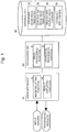
- Fig. 1 is a block diagram illustrating a main part of a medical image display processing device in one embodiment according to the present invention.
- the medical image display processing device of the present embodiment includes a user interface 10, an image-statistical processing unit 20, and a database unit 30.
- the user interface 10 has an image inputting function 12 for inputting input images from an MRI device and a result displaying function 14 for displaying the results of program-processing performed by the processing unit 20 on a display.
- the processing unit 20 has an image processing function 22 for processing MRI morphological images, perfusion weighted images, and ASL-EPI images to be described later, inputted from the user interface 10, and a statistical processing function 24 for performing, for example, various statistical computations.
- Standard brain image templates 32, gray matter brain image templates 34, an able-bodied person image database 36, standard brain masks 38, etc. that are used for processing, to be described later, by the processing unit 20 have been stored in the database unit 30.
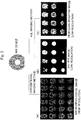
- MRI morphological images (A) taken by a conventional imaging method ASL-EPI images (B) being low-resolution morphological images and taken by the ASL imaging method, and perfusion weighted images (C) being functional images and taken by the ASL imaging method are inputted from the MRI device.
- ASL-EPI images (B) being low-resolution morphological images and taken by the ASL imaging method
- C being functional images and taken by the ASL imaging method
- each ellipse represents an image or a processed product.
- perfusion weighted images and ASL-EPI images are inputted as input images.
- the image reconstruction is a process, in which the two types of images are re-sampled three-dimensionally and divided into voxels with equal size in all directions to make the units of the three-dimensional voxels, corresponding to pixels in two-dimensions, of the two types of images the same size.
- mask images are produced from the ASL-EPI images by mask production (step 2).
- Fig. 4 shows a mask image (B) produced by binarizing the ASL-EPI image (A) on the upper side.
- the mask image is produced from the ASL-EPI image to mask regions of the perfusion weighted image other than the region of the cerebral parenchyma.
- the low-resolution ASL-EPI image has characteristics that the pixel values in the region of the cerebral parenchyma are higher than those of the other regions. Such characteristics are used to perform binarization by thresholding to thereby produce a mask image in which the pixel values in the region of the cerebral parenchyma are set to 1 and the pixel values in the other regions are set to 0 (mask).
- the threshold value may be a predetermined fixed value or may be adaptively determined using, for example, the Otsu binarization algorithm.
- a method shown in Fig. 5 may be used. With this method, a mask image can be obtained with higher precision as compared to the method shown in Fig. 4 . More specifically, a low-resolution ASL-EPI image shown in Fig. 5(A) is subjected to tissue separation processing to extract regions of white matter, gray matter, and cerebrospinal fluid, and the regions of the white matter and gray matter are combined and binarized, as shown in Fig. 5(B) . Then filling processing is performed to obtain a mask image shown in Fig. 5(C) . The threshold value is set in the same manner as in Fig. 4 .
- the mask images produced by any of the above methods are applied to the perfusion weighted images, which are functional images, to perform mask processing (step 3).
- the mask processing is applied to the perfusion weighted images in (C) of Fig. 2 that have been subjected to the above step 1.
- the mask processing is performed on each slice image, and the voxel values in regions other than the region of the cerebral parenchyma are set to 0.
- mask boundaries are determined using the mask images produced in the above step 2 (step 4), and unnecessary slices are cut from the perfusion weighted images subjected to the mask processing in the above step 3 (step 5).
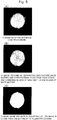
- Fig. 6(A) is a perspective view of the produced mask images.
- the black color represents a pixel value of 1, and the white color represents a pixel value of 0.
- the determination of the mask boundaries is a processing for removing vertical and horizontal slices not containing the region of the cerebral parenchyma (the region with a pixel value of 1) from the mask images.
- the i+1-th slice that is a first slice containing the region with a pixel value of 1 in a downward direction from the upper edge is determined as a mask boundary, and the first to i-th slices are determined as unnecessary slices and cut away to form mask images shown in Fig. 6(B) .
- the produced perfusion weighted image contains only the region of the cerebral parenchyma. This procedure is repeated for all the vertical and horizontal directions, and the slices of the perfusion weighted images can thereby be defined only by the remaining slices of the mask images.
- the mask boundaries may be determined by removing a predetermined number of slices that is set in advance.
- a perfusion weighted image including only the extracted region of the cerebral parenchyma can be produced, as shown in Fig. 7(B) . Therefore, only the region of the cerebral parenchyma in a perfusion weighted image can be displayed on the display using the result displaying function 14, and an ASL-EPI image can be overlaid on the displayed perfusion weighted image. Therefore, diagnosis-assisting information quite useful for health professionals can be provided.
- the present embodiment is the same as the basic processing procedures described with reference to the flowchart in Fig. 3 in that low-resolution (abbreviated as Low-Reso. in the figure) perfusion weighted images and low-resolution ASL-EPI images taken by the ASL method are inputted as input images.
- low-resolution abbreviated as Low-Reso. in the figure
- high-resolution abbreviated as High-Reso. in the figure
- MRI morphological images taken by a conventional method are also used as input images.
- the ASL-EPI images by the former method are taken in the same sequence as that for the perfusion weighted images, and therefore the positions in these images completely match each other.
- the MRI morphological images by the latter method are taken in a sequence continuous with the sequence for the ASL method or in a different sequence, and therefore the positions and angles in the MRI morphological images may be different from those in the ASL-EPI and perfusion weighted images.
- the coordinate system used in the former method is referred to as an ASL coordinate system or a subject brain coordinate system A (hereinafter may be referred to as a coordinate system A), and the coordinate system used in the latter method is referred to as an MRI coordinate system or a subject brain coordinate system B (hereinafter may be referred to as a coordinate system B).
- the determination of mask boundaries and elimination of unnecessary slices performed in steps 4 and 5 of the basic processing procedures and the perfusion weighted images produced thereby are omitted from the figure.
- perfusion weighted images of only the regions of the cerebral parenchyma are extracted in the coordinate system A (ASL coordinate system) by mask processing in step 13.
- the coordinate system for the MRI morphological images is the coordinate system B (MRI coordinate system).
- a transformation field for transformation from the coordinate system A to the coordinate system B is estimated using spatial normalization in which an ASL-EPI image is fitted to an MRI morphological image used as a template (step 14).
- the estimation of the transformation field is to estimate linear transformation and nonlinear transformation parameters for the ASL-EPI image that minimize the sum of squares of errors between the ASL-EPI images and the MRI morphological images.
- any of methods described in Non-Patent Literatures 2, 3, and 4 can be used.
- registration is the purpose of the spatial normalization, and therefore linear transformation, particularly only translation and rotation (rigid body transformation), is used.
- linear transformation particularly only translation and rotation (rigid body transformation)
- the brain of the subject is transformed to a standard brain as in steps 24, 32, 52, and 72 described later, registration and deformation are necessary, and linear transformation and nonlinear transformation are performed.
- the perfusion weighted images in the coordinate system A that have been extracted and produced by the mask processing are transformed into images in the coordinate system B for the MRI morphological images by the spatial normalization using the transformation fields (step 15).
- the term "Normalize : Write” in the figure means that the estimated transformation field is used to transform an image.
- the transformation field used here means a transformation matrix determined by fitting an ASL-EPI image to an MRI morphological image used as a template.
- the transformation field is represented as a set of three-dimensional vectors that indicate displaced coordinate positions obtained by the transformation of the original coordinate positions.
- two-dimensional representation is used for simplicity. The basic principles of other various transformation fields used later are the same as the above principle.
- the perfusion weighted images containing the extracted regions of the cerebral parenchyma can be displayed to be overlaid on the high-resolution MRI morphological images correctly. Therefore, the perfusion weighted images can be displayed together with more clearly displayed cranium regions in position, and more useful information can be provided.
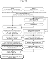
- perfusion weighted images and ASL-EPI images are used as input images, and the same processing as in the above steps 1 to 4 is used to produce perfusion weighted images of only the region of the cerebral parenchyma (steps 21 to 23).
- the processing related to the determination of mask boundaries is omitted from the figure.
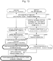
- each of the perfusion weighted images in the subject brain coordinate system A that have been produced in step 23 is transformed into an image in the standard brain coordinate system.
- a spatial transformation field used to transform an ASL-EPI image into an image on the standard brain is estimated using spatial normalization in which the ASL-EPI image is fitted to a T1 weighted image serving as a template and stored in the database unit 30 as a standard brain image template 32 (step 24).
- the transformation field formed by estimation is used to perform the spatial normalization to transform the perfusion weighted image in the coordinate system A into an image in the standard brain coordinate system (step 25).
- Each perfusion weighted image that contains only the region of the cerebral parenchyma transformed in the standard brain coordinate system is compared with the data of perfusion weighted images in the able-bodied people image database 36 stored in the database unit 30. Then the voxel values in the entire perfusion weighted image that represent the intensity of perfusion (blood flow) are converted to statistical values (Z scores) indicating the degree of deviation from the intensity of perfusion in an able-bodied person to produce a perfusion weighted Z score map on the standard brain(step 26).
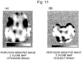
- the image of the perfusion weighted Z score map is shown in Fig. 11 (A) .
- an inverse transformation field used for transformation from the standard brain coordinate system to the subject brain coordinate system A is generated by the inverse transformation of the transformation field formed in the above step 24 (step 27). Then the inverse transformation field is applied to the perfusion weighted Z score map in the standard brain coordinate system to generate a perfusion weighted Z score map in the subject brain coordinate system that is exaggeratedly illustrated in Fig. 11(B) (step 28).
- a forward transformation field f shown by arrows (solid lines) in Fig. 12(A) is the same as that in Fig. 9 .
- an inverse transformation field g of the forward transformation field f is determined, a coordinate system in which the values of coordinates (filled circles) transformed by the forward transformation field f are replaced with the values of the original coordinates (open circles) is generated as shown in Fig. 12(B) . Then the coordinate values of the original coordinate positions (open circles) are determined by linear interpolation.
- These coordinate values represent the inverse transformation g of the forward transformation f with the original coordinate values used as reference.
- the coordinates (x, y) of lattice points represented by open triangles are determined by linear interpolation and used as inverse-transformed coordinate values.
- the (inverse) transformation field g is represented by arrows (dotted lines).
- the brain images of a subject are transformed into an image on a standard brain using anatomical normalization (spatial normalization) corresponding to the above-described spatial normalization (see, for example, Patent Literature 3).
- anatomical normalization spatial normalization
- the blood flow images themselves are fitted to standard brain templates by anatomical normalization.
- the region of the cerebral surface may contain blood flow values (signals) due to noise, and the skull may have a wide region in which the blood flow level is low because of, for example, infract.
- the shape of the brain is significantly different from the shape of the standard brain templates, and this causes a problem in that the precision of the anatomical normalization deteriorates.
- the perfusion weighted images of only the region of the cerebral parenchyma are transformed into images in the standard brain coordinate system, such a problem does not occur. Therefore, high-precision anatomical normalization of perfusion weighted images can be achieved.
- the perfusion weighted images of only the region of the cerebral parenchyma can be displayed. Additionally, in the perfusion weighted images, a region in which the level of blood flow is significantly lower than that in the able-bodied person can be specified. In addition, since the output is obtained in two coordinate systems including the coordinate system for the standard brain and that for the subject brain (original images), useful diagnosis-assisting information can be provided.
- perfusion weighted images and ASL-EPI images are used as input images, and the process until image reconstruction in step 31 is the same as that in the second embodiment.
- transformation fields to the standard brain are first formed from the reconstructed ASL-EPI images using spatial normalization in the same manner as in the above step 24 (step 32), and the transformation fields are applied to the perfusion weighted images before mask processing to transform them into images in the standard brain coordinate system (step 33).
- the perfusion weighted images transformed into the standard brain are subjected to mask processing using the known standard brain masks 38 stored in the database unit 30 (step 34).
- perfusion weighted images of only the region of the cerebral parenchyma are extracted by the mask processing, as in the second embodiment. Since these images have been transformed into the standard brain, they can be directly compared with the images of the able-bodied person to produce Z score maps for the perfusion weighted images. Then inverse transformation fields are produced by inverse transformation similar to that in the above step 27 described above (step 36), and the produced inverse transformation fields are applied to the Z score maps on the standard brain to produce Z score maps in the subject brain coordinate system (step 37).
- the precision of transformation to the standard coordinate system is slightly lower than that when the mask images produced from the ASL-EPI images are used.
- the mask processing can be performed using the existing standard brain masks in a simple manner, and the same effects as in the third embodiment can be obtained.
- the input images also include MRI morphological images in the coordinate system B.
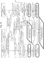
- the processing from image reconstruction in step 41 to the application of inverse transformation in step 48 is basically the same as the processing in steps 21 to 28 in the second embodiment, although the perfusion weighted images produced by the mask processing in step 43 are omitted.
- Z score maps are transformed into an image in the coordinate system B by the inverse transformation in step 48, the configuration of the inverse transformation fields applied is different. This will be described later.
- the degree of atrophy of brain tissues can be displayed as Z score maps based on the MRI morphological images inputted by the conventional method.
- the MRI morphological images in the subject brain coordinate system B are subjected to tissue separation(step 51).
- the tissue separation preformed here is separation of the white matter and gray matter from the T1 weighted images.
- the sizes and shapes of the separated tissues are fitted to those of the standard brain by spatial normalization (step 52).
- a template "gray.mnc" used for the normalization means a standard brain template of the gray matter.
- the normalized tissue images are smoothened for, for example, removal of noise (step 53) and then compared with the tissue image data of the able-bodied person to compute Z scores indicating the degree of atrophy of the brain tissues for the entire tissue images, and Z score maps in the standard brain coordinate system are thereby generated (step 54).
- the standard brain Z score maps produced by comparison with the brain of the able-bodied person in step 54 are transformed into an image in the coordinate system B by inverse transformation(step 55), and the brain tissue Z score maps in the coordinate system B can be displayed together with the perfusion weighted Z score maps in the coordinate system B generated by inverse transformation in the above step 48.
- the present embodiment uses transformation fields (A) for converting the subject brain coordinate system A to the subject brain coordinate system B, transformation fields (B) for converting the subject brain coordinate system A to the standard brain, transformation fields (C) for converting the subject brain coordinate system B to the standard brain, and inverse transformation fields (D) for converting the standard brain to the coordinate system B.
- the transformation fields (A) are formed by spatial normalization in step 44.
- the transformation fields (B) applied in the above step 45 are formed in step 49 by combining the transformation fields (A) and the transformation fields (C) formed by spatial normalization in the above step 52.
- the inverse transformation fields (D) applied for the inverse transformation in the above steps 48 and 55 are formed by inverse transformation of the transformation fields (C) in step 47.
- a region in which distributions in the perfusion and morphology are significantly lower than those of the able-bodied person can be specified.
- the significant reduction in distribution in the perfusion weighted images means a reduction in blood flow
- the significant reduction in distribution in the MRI morphological images means atrophy.
- the present embodiment is substantially the same as the fourth embodiment except that, as in the third embodiment, the perfusion weighted images are first transformed into an image on the standard brain by spatial normalization in which the transformation fields (B) are applied (step 63) and then mask processing is performed using the known standard brain Z masks (step 64). Therefore, steps 65 and 67 are the same as steps 46 and 48 in Fig. 14 , and the respective processings in steps 71 to 75 for tissue separation are the same as the processings in steps 51 to 55 described above. In addition, all the (inverse) transformation fields are the same as those in the fourth embodiment, and the description thereof will be omitted.
- the mask processing is simplified as in the third embodiment, and the same effects as those in the fourth embodiment can be obtained.
- the perfusion weighted images outputted by the ASL imaging method and the MRI morphological images can be registered with high precision (positioning).
- various images can be overlaid and displayed, such as images in the standard brain coordinate system including the standard brain morphological images, standard brain blood flow images, morphological image Z score maps, and perfusion weighted Z score maps, and images in the subject brain coordinate system including the subject brain morphological images, subject brain perfusion weighted images, inverse-transformed morphological Z score maps, and inverse-transformed perfusion weighted Z score maps. Therefore, various types of diagnosis assistance can be provided using the morphological images and the functional images.
- the perfusion weighted images inputted by the ASL imaging method are transformed into an image in the standard brain coordinate system before the mask processing, it is described that the mask processing is performed using the standard brain mask, but this is not a limitation.
- the ASL-EPI images inputted simultaneously with the perfusion weighted images may also be transformed into an image in the standard brain coordinate system, and mask images produced from the resultant ASL-EPI images may be used.
- the perfusion weighted images are inputted as functional images, but this is not a limitation.
- CBFs may be inputted.
- images of absolute cerebral blood flows are obtained as result images.
- the present invention is useful as a medical image display processing method, device, and program used when brain images inputted through MRI (Magnetic Resonance Imaging) are subjected to image processing to assist the diagnosis of brain diseases.
- MRI Magnetic Resonance Imaging
Landscapes
- Health & Medical Sciences (AREA)
- Engineering & Computer Science (AREA)
- Physics & Mathematics (AREA)
- Nuclear Medicine, Radiotherapy & Molecular Imaging (AREA)
- Life Sciences & Earth Sciences (AREA)
- General Health & Medical Sciences (AREA)
- Radiology & Medical Imaging (AREA)
- General Physics & Mathematics (AREA)
- Medical Informatics (AREA)
- High Energy & Nuclear Physics (AREA)
- Computer Vision & Pattern Recognition (AREA)
- Animal Behavior & Ethology (AREA)
- Signal Processing (AREA)
- Surgery (AREA)
- Heart & Thoracic Surgery (AREA)
- Biomedical Technology (AREA)
- Public Health (AREA)
- Veterinary Medicine (AREA)
- Theoretical Computer Science (AREA)
- Pathology (AREA)
- Molecular Biology (AREA)
- Condensed Matter Physics & Semiconductors (AREA)
- Biophysics (AREA)
- Artificial Intelligence (AREA)
- Quality & Reliability (AREA)
- Vascular Medicine (AREA)
- Hematology (AREA)
- Cardiology (AREA)
- Physiology (AREA)
- Magnetic Resonance Imaging Apparatus (AREA)
Claims (11)
- Medizinisches Bildverarbeitungsverfahren mit den Schritten:Erfassen eines funktionalen Bildes in einem ASL-Koordinatensystem von einem Kopf eines Patienten mittels eines ASL-Bildgebungsverfahrens durch Einsatz einer MRI-Vorrichtung,Unterziehen des erfassten funktionalen Bildes einer Maskenbearbeitung, um nur einen Bereich eines zerebralen Parenchyms zu extrahieren, undDarstellen des erhaltenen funktionalen Bildes, das nur die extrahierte Region des zerebralen Parenchyms enthält,gekennzeichnet durchVorbereiten eines funktionalen Bildes nur der Region des zerebralen Parenchyms einer gesunden Person und Eintragen des vorbereiteten funktionalen Bildes in ein Standardgehirnkoordinatensystem,Durchführen des Maskenbearbeitungsprozesses (S3, S13, S23, S24, S43, S64) zum Extrahieren nur der Region des zerebralen Parenchyms mittels eines Maskenbildes, das aus einem ASL-EPI Bild hergestellt wurde, das ein morphologisches Bild ist, das gleichzeitig mit dem funktionalen Bild in derselben Sequenz der ASL-Bildgebungsverfahrens erfasst wurde,Bestimmen eines Transformationsfeldes aus dem ASL-Koordinatensystem auf das Standardgehirnkoordinatensystem basierend auf dem ASL-EPI Bild,vor oder nach der Maskenbearbeitung Transformieren des funktionalen Bildes, das durch das ASL-Bildgebungsverfahren erfasst wurde, mittels des Transformationsfeldes in ein Bild in einem Standardgehirnkoordinatensystem, Statistisches Vergleichen (S26, S35, S46, S65) des resultierenden funktionalen Bildes nur der Region des zerebralen Parenchyms in dem Standardgehirnkoordinatensystem mit dem vorbereiteten und erfassten funktionalen Bild von nur der Region des zerebralen Parenchyms der gesunden Person, undHerstellen und Darstellen einer perfusionsgewichteten Z-Scorekarte in dem Standardgehirnkoordinatensystem.
- Medizinische Bildverarbeitungsverfahren nach Anspruch 1, mit den zusätzlichen Schritten des Transformierens der perfusionsgewichteten Z-Scorekarte in dem Standardgehirnkoordinatensystem in ein Bild in dem ASL-Koordinatensystem durch inverse Transformationen (S28, S37, S48, S67) und danach Darstellen des transformierten Bildes.
- Medizinisches Bildverarbeitungsverfahren nach Anspruch 1, zusätzlich mit den Schritten des Erfassens eines morphologischen MRI-Bildes vom Kopf des Patienten mitters der MRI-Vorrichtung, Unterziehen des erfassten morphologischen MRI-Bildes einer Gewebetrennung (S51, S71), um ein Gewebebild abzutrennen, Transformieren des abgetrennten Gewebebildes in ein Bild in dem Standardgehirnkoordinatensystem, statisches Vergleichen (S54, S74) des erhaltenen Gewebebildes in dem Standardgehirnkoordinatensystem mit einem vorbereiteten Gewebebild der gesunden Person um eine Z-Scorekarte von Gehirngewebe in dem Standardgehirnkoordinatensystem zu erzeugen, und Darstellen der Z-Scorekarte des Gehirngewebes zusammen mit der perfusionsgewichteten Z-Scorekarte in dem Standardgehirnkoordinatensystem.
- Medizinisches Bildverarbeitungsverfahren nach Anspruch 1, zusätzlich mit den Schritten des Erfassens eines morphologischen MRI-Bildes vom Kopf des Patienten mittels der MRI-Vorrichtung, Separieren von Gewebe (S51, S71) von dem erfassten morphologischen MRI-Bild, Transformieren des separierten Gewebebildes in ein Bild in den Standardgehirnkoordinatensystem, statistisches Vergleichen (S54, S74) des erhaltenen Gewebebildes in dem Standardgehirnkoordinatensystem mit einem vorbereiteten Gewebebild einer gesunden Person, um eine Z-Scorekarte von Gehirngewebe, in dem Standardgehirnkoordinatensystem zu erhalten, und Darstellen der Z-Scorekarte des Gehirngewebes zusammen mit der perfusionsgewichteten Z-Scorekarte in dem Standardgehirnkoordinatensystem, und
beim Bestimmen des Transformationsfeldes zum Transformieren des ASL-EPI Bildes in ein Bild in dem Standardgehirnkoordinatensystem basierend auf dem ASL-EPI Bild ein Transformationsfeld von dem Koordinatensystem des ASL-EPI Bildes des Patienten zu einem Koordinatensystem des morphologischen MRI-Bildes desselben Patenten und ein Transformationsfeld von dem Koordinatensystem des morphologischen MRI-Bildes des Patienten zu dem Koordinatensystem des Standardgehirns jeweils bestimmt werden und das Transformationsfeld von dem Koordinatensystem des ASL-EPI Bildes zu dem Koordinatensystem des Standardgehirns durch Verbinden (S49, S76) der beiden Transformationsfelder bestimmt wird. - Medizinisches Bildverarbeitungsverfahren nach Anspruch 3 oder 4, zusätzlich mit den Schritten des Transformierens (S48, S76; S55, S75) der perfusionsgewichteten Z-Scorekarte und der Z-Scorekarte des Gehirngewebes in dem Standardgehirnkoordinatensystem in Bilder in einem MRI-Koordinatensystem auf der Basis des morphologischen MRI-Bildes und dann Darstellen der transformierten Bilder.
- Medizinische Bildverarbeitungsvorrichtung mit:Bildeingabemitteln (12), die dafür eingerichtet sind, ein funktionales Bild in einem ASL-Koordinatensystem von einem Kopf eines Patienten durch ein ASL-Bildgebungsverfahrens mittels einer MRI-Vorrichtung zu erfassen, undBildverarbeitungsmittel (22), die dafür eingerichtet sind, das erfasste funktionale Bild einer Maskenbearbeitung zu unterziehen, um nur einen Bereich eines zerebralen Parenchyms zu extrahieren, wobei die Bildverarbeitungsmittel (22) zudem dafür eingerichtet sind, das resultierende funktionale Bild von nur der extrahierten Region des zerebralen Parenchyms darzustellen,dadurch gekennzeichnet, dass die Bildverarbeitungsmittel (22) zudem dafür ausgelegt sind, ein funktionales Bild von nur einem Bereich zerebralen Parenchyms einer gesunden Person vorzubereiten und das vorbereitete funktionale Bild in einem Standardgehirnkoordinatensystem zu erfassen, undwobei die Bildverarbeitungsmittel (22) zudem dafür eingerichtet sind, die Maskenbearbeitung zum Extrahieren nur der Region des zerebralen Parenchyms durchzuführen, indem ein Maskenbild verwendet wird, das von einem ASL-EPI Bild erhalten wurde, das ein morphologisches Bild ist, das gleichzeitig mit dem funktionalen Bild in derselben Sequenz durch das ASL-Bildgebungsverfahren erhalten wurde, und zudemdie Bildverarbeitungsmittel (22) zudem dafür eingerichtet sind, ein Transformationsfeld von dem ASL-Koordinatensystem zu einem Standardgehirnkoordinatensystem basierend auf dem ASL-EPI Bild zu bestimmen, um vor oder nach der Maskenbearbeitung das funktionale Bild, das durch das ASL-Bildgebungsverfahren erhalten wurde, unter Verwendung des Transformationsfeldes in ein Bild in einem Standardgehirnkoordinatensystem zu transformieren, und dann statistisch das resultierende funktionale Bild von nur der Region des zerebralen Parenchyms in dem Standardgehirnkoordinatensystem mit dem vorbereiteten und erfassten funktionalen Bild von nur der Region der zerebralen Parenchyms der gesunden Person zu vergleichen, um eine perfusionsgewichtete Z-Scorekarte in dem Standardgehirnkoordinatensystem zu erhalten und darzustellen.
- Medizinische Bildverarbeitungsvorrichtung nach Anspruch 6, wobei die Bildverarbeitungsmittel (22) dafür eingerichtet sind, die perfusionsgewichtete Z-Scorekarte in dem Standardgehirnkoordinatensystem durch inverse Transformationen in ein Bild in dem ASL-Koordinatensystem zu transformieren und dann die resultierende perfusionsgewichtete Z-Scorekarte darzustellen.
- Medizinische Bildverarbeitungsvorrichtung nach Anspruch 6, die dafür eingerichtet ist, mittels der MRI-Vorrichtung ein morphologisches MRI-Bild von dem Kopf des Patienten zu erfassen, wobei die Bildverarbeitungsmittel (22) dafür eingerichtet sind, eine Gewebetrennung an dem erfassten morphologischen MRI-Bild durchzuführen, um ein Gewebebild abzutrennen, das abgetrennte Gewebebild in ein Bild in dem Standardgehirnkoordinatensystem zu transformieren, statistisch das resultierende Gewebebild in dem Standardgehirnkoordinatensystem mit einem vorbereiteten Gewebebild der gesunden Person zu vergleichen, um eine Z-Scorekarte von Gehirngewebe in dem Standardgehirnkoordinatensystem zu erhalten, und um die Gehirngewebe Z-Scorekarte zusammen mit der perfusionsgewichteten Z-Scorekarte in dem Standardgehirnkoordinatensystem darzustellen.
- Medizinische Bildverarbeitungsvorrichtung nach Anspruch 6, die dafür eingerichtet ist, mittels der MRI-Vorrichtung ein morphologisches MRI-Bild vom Kopf des Patienten zu erfassen, wobei die Bildverarbeitungsmittel (22) dafür eingerichtet ist, eine Gewebetrennung an dem erfassten morphologischen MRI-Bild durchzuführen, um das abgetrennte Gewebebild in ein Bild in dem Standardgehirnkoordinatensystem zu transformieren, das erhaltene Gewebebild statistisch in dem Standardgehirnkoordinatensystem mit einem vorbereiteten Gewebebild einer gesunden Person zu vergleichen, um eine Z-Scorekarte von Gehirngewebe in dem Standardgehirnkoordinatensystem zu erhalten und die Z-Scorekarte des Gehirngewebes zusammen mit der perfusionsgewichteten Z-Scorekarte in dem Standardgehirnkoordinatensystem darzustellen, und,
dafür eingerichtet ist, bei der Bestimmung des Transformationsfeldes zur Transformation des ASL-EPI Bildes in ein Bild in dem Standardgehirnkoordinatensystem basierend auf dem ASL-EPI Bild jeweils ein Transformationsfeld von dem Koordinatensystem des ASL-EPI Bildes des Patienten zu einem Koordinatensystem des morphologischen MRI-Bildes desselben Patienten und ein Transformationsfeld von dem Koordinatensystem des morphologischen MRI-Bildes des Patienten zu dem Koordinatensystem des Standardgehirns zu bestimmen und das Transformationsfeld zum Transformieren des ASL-EPI Bildes in ein Bild in dem Koordinatensystem des Standardgehirns durch Kombinieren der beiden Transformationsfelder zu bestimmen. - Medizinische Bildverarbeitungsvorrichtung nach Anspruch 6 oder 9, wobei die Bildverarbeitungsmittel (22) dafür eingerichtet sind, die perfusionsgewichtete Z-Scorekarte und die Z-Scorekarte von Gehirngewebe in ein Bild in dem Standardgehirnkoordinatensystem in ein MRI-Koordinatensystem auf der Basis des morphologischen MRI-Bildes zu transformieren und die erhaltenen Karten darzustellen.
- Computerlesbares Programm, dadurch gekennzeichnet, dass es dafür eingerichtet ist, das medizinische Bildverarbeitungsverfahren nach einem der Ansprüche 1 bis 5 auf einem Computer durchzuführen.
Applications Claiming Priority (2)
| Application Number | Priority Date | Filing Date | Title |
|---|---|---|---|
| JP2009221391A JP5229175B2 (ja) | 2009-09-25 | 2009-09-25 | 医用画像表示処理方法、装置およびプログラム |
| PCT/JP2010/066236 WO2011037093A1 (ja) | 2009-09-25 | 2010-09-17 | 医用画像表示処理方法、装置およびプログラム |
Publications (3)
| Publication Number | Publication Date |
|---|---|
| EP2481349A1 EP2481349A1 (de) | 2012-08-01 |
| EP2481349A4 EP2481349A4 (de) | 2015-12-02 |
| EP2481349B1 true EP2481349B1 (de) | 2018-12-05 |
Family
ID=43795841
Family Applications (1)
| Application Number | Title | Priority Date | Filing Date |
|---|---|---|---|
| EP10818766.7A Active EP2481349B1 (de) | 2009-09-25 | 2010-09-17 | Verfahren, vorrichtung und programm zur verarbeitung von asl-mrt bildern |
Country Status (4)
| Country | Link |
|---|---|
| US (1) | US8750584B2 (de) |
| EP (1) | EP2481349B1 (de) |
| JP (1) | JP5229175B2 (de) |
| WO (1) | WO2011037093A1 (de) |
Families Citing this family (15)
| Publication number | Priority date | Publication date | Assignee | Title |
|---|---|---|---|---|
| WO2010004365A1 (en) | 2008-07-10 | 2010-01-14 | Ecole Polytechnique Federale De Lausanne (Epfl) | Functional optical coherent imaging |
| CN103249358B (zh) * | 2010-12-02 | 2015-09-09 | 大日本印刷株式会社 | 医用图像处理装置 |
| KR101805624B1 (ko) * | 2011-08-29 | 2017-12-08 | 삼성전자주식회사 | 장기 모델 영상 생성 방법 및 장치 |
| JP5970766B2 (ja) * | 2011-09-26 | 2016-08-17 | 大日本印刷株式会社 | 医用画像処理装置、医用画像処理方法、プログラム |
| WO2013160861A1 (en) * | 2012-04-27 | 2013-10-31 | Aïmago S.A. | Optical coherent imaging medical device |
| US9734573B2 (en) * | 2013-04-17 | 2017-08-15 | The United States Of America, As Represented By The Secretary, Dept. Of Health And Human Services | Methods and systems for automatically determining magnetic field inversion time of a tissue species |
| JP6362958B2 (ja) * | 2013-09-05 | 2018-07-25 | キヤノンメディカルシステムズ株式会社 | 磁気共鳴イメージング装置 |
| US11647915B2 (en) * | 2014-04-02 | 2023-05-16 | University Of Virginia Patent Foundation | Systems and methods for medical imaging incorporating prior knowledge |
| US9911206B2 (en) * | 2015-01-13 | 2018-03-06 | Siemens Healthcare Gmbh | Time efficient ASL imaging with segmented multiband acquisition |
| JP2016180649A (ja) * | 2015-03-24 | 2016-10-13 | 日本メジフィジックス株式会社 | 画像処理装置、画像処理方法、及びプログラム |
| JP6548615B2 (ja) * | 2016-08-23 | 2019-07-24 | 富士フイルム株式会社 | 磁場歪み算出装置、方法およびプログラム |
| KR101950815B1 (ko) * | 2017-08-25 | 2019-02-21 | 뉴로핏 주식회사 | 패치 가이드 방법 및 프로그램 |
| JP7125312B2 (ja) * | 2018-09-07 | 2022-08-24 | 富士フイルムヘルスケア株式会社 | 磁気共鳴撮像装置、画像処理装置、及び、画像処理方法 |
| CN110279417B (zh) * | 2019-06-25 | 2023-03-31 | 沈阳东软智能医疗科技研究院有限公司 | 识别主动脉血管的方法、装置及设备 |
| JP7572187B2 (ja) * | 2020-08-31 | 2024-10-23 | 富士フイルム株式会社 | 磁気共鳴イメージング装置 |
Family Cites Families (14)
| Publication number | Priority date | Publication date | Assignee | Title |
|---|---|---|---|---|
| US5871013A (en) * | 1995-05-31 | 1999-02-16 | Elscint Ltd. | Registration of nuclear medicine images |
| JP4368988B2 (ja) | 1999-10-15 | 2009-11-18 | Geヘルスケア・ジャパン株式会社 | Mri装置 |
| JP4346184B2 (ja) * | 1999-12-28 | 2009-10-21 | 株式会社東芝 | Mri装置 |
| JP4454212B2 (ja) | 2001-08-31 | 2010-04-21 | 富士フイルムRiファーマ株式会社 | 画像関連データ処理方法 |
| US8805619B2 (en) * | 2002-10-28 | 2014-08-12 | The General Hospital Corporation | Tissue disorder imaging analysis |
| JP3699963B2 (ja) * | 2003-07-01 | 2005-09-28 | 株式会社東芝 | 磁気共鳴映像装置 |
| WO2005023086A2 (en) * | 2003-08-25 | 2005-03-17 | University Of North Carolina At Chapel Hill | Systems, methods, and computer program products for analysis of vessel attributes for diagnosis, disease staging, and surgical planning |
| JP4025823B2 (ja) * | 2004-02-24 | 2007-12-26 | 国立精神・神経センター総長 | 脳疾患の診断支援方法及び装置 |
| US7627370B2 (en) * | 2004-10-20 | 2009-12-01 | Marks Donald H | Brain function decoding process and system |
| WO2007123799A2 (en) * | 2006-04-03 | 2007-11-01 | The Trustees Of The University Of Pennsylvania | Assessing subject's reactivity to psychological stress using fmri |
| US8320647B2 (en) * | 2007-11-20 | 2012-11-27 | Olea Medical | Method and system for processing multiple series of biological images obtained from a patient |
| EP2274268B1 (de) * | 2008-04-09 | 2011-12-14 | Basf Se | Verfahren zur vorbehandlung von hydroaminierungskatalysatoren |
| US8626264B1 (en) * | 2008-04-09 | 2014-01-07 | James T. Beran | Obtaining information about brain activity |
| EP2161594B1 (de) * | 2008-09-09 | 2017-11-08 | Multi Magnetics Incorporated | System und Verfahren zur Dämpfungskorrektur in der hybriden medizinischen Bildgebung |
-
2009
- 2009-09-25 JP JP2009221391A patent/JP5229175B2/ja active Active
-
2010
- 2010-09-17 WO PCT/JP2010/066236 patent/WO2011037093A1/ja not_active Ceased
- 2010-09-17 US US13/497,447 patent/US8750584B2/en active Active
- 2010-09-17 EP EP10818766.7A patent/EP2481349B1/de active Active
Non-Patent Citations (1)
| Title |
|---|
| None * |
Also Published As
| Publication number | Publication date |
|---|---|
| EP2481349A4 (de) | 2015-12-02 |
| JP5229175B2 (ja) | 2013-07-03 |
| US8750584B2 (en) | 2014-06-10 |
| WO2011037093A1 (ja) | 2011-03-31 |
| JP2011067424A (ja) | 2011-04-07 |
| EP2481349A1 (de) | 2012-08-01 |
| US20120195485A1 (en) | 2012-08-02 |
Similar Documents
| Publication | Publication Date | Title |
|---|---|---|
| US8750584B2 (en) | Medical image display processing method, device, and program | |
| Namburete et al. | Normative spatiotemporal fetal brain maturation with satisfactory development at 2 years | |
| Rex et al. | A meta-algorithm for brain extraction in MRI | |
| Eskildsen et al. | BEaST: brain extraction based on nonlocal segmentation technique | |
| Altaye et al. | Infant brain probability templates for MRI segmentation and normalization | |
| Kikinis et al. | Quantitative follow‐up of patients with multiple sclerosis using MRI: technical aspects | |
| JP2011067424A5 (de) | ||
| US20050244036A1 (en) | Method and apparatus for evaluating regional changes in three-dimensional tomographic images | |
| US11842491B2 (en) | Novel, quantitative framework for the diagnostic, prognostic, and therapeutic evaluation of spinal cord diseases | |
| Gilanie et al. | Object extraction from T2 weighted brain MR image using histogram based gradient calculation | |
| Liu et al. | Robust cortical thickness morphometry of neonatal brain and systematic evaluation using multi-site MRI datasets | |
| Suckling et al. | Removal of extracerebral tissues in dual-echo magnetic resonance images via linear scale-space features | |
| CN119295473A (zh) | 一种多模态动态结构-功能多层脑网络计算方法及终端 | |
| Sun et al. | Automated template-based PET region of interest analyses in the aging brain | |
| Basukala et al. | Automated segmentation of substantia nigra and red nucleus using quantitative susceptibility mapping images: Application to Parkinson's disease | |
| US11257227B2 (en) | Brain image normalization apparatus, brain image normalization method, and brain image normalization program | |
| Urru et al. | An automatic pipeline for atlas-based fetal and neonatal brain segmentation and analysis | |
| Wang et al. | Semi-automatic segmentation of the fetal brain from magnetic resonance imaging | |
| Devi et al. | Automatic segmentation of infant brain MR images: With special reference to myelinated white matter | |
| JP2006158791A (ja) | 頭蓋内容積および局所脳構造物解析プログラム、記録媒体および頭蓋内容積および局所脳構造物解析方法 | |
| Jafrasteh et al. | MGA-Net: A novel mask-guided attention neural network for precision neonatal brain imaging | |
| Myint et al. | Effective kidney segmentation using gradient based approach in abdominal CT images | |
| Fripp et al. | MR-less high dimensional spatial normalization of 11C PiB PET images on a population of elderly, mild cognitive impaired and Alzheimer disease patients | |
| HK1171640B (en) | Method, device, and program for processing images obtained from asl mri | |
| HK1171640A (en) | Method, device, and program for processing images obtained from asl mri |
Legal Events
| Date | Code | Title | Description |
|---|---|---|---|
| PUAI | Public reference made under article 153(3) epc to a published international application that has entered the european phase |
Free format text: ORIGINAL CODE: 0009012 |
|
| 17P | Request for examination filed |
Effective date: 20120323 |
|
| AK | Designated contracting states |
Kind code of ref document: A1 Designated state(s): AL AT BE BG CH CY CZ DE DK EE ES FI FR GB GR HR HU IE IS IT LI LT LU LV MC MK MT NL NO PL PT RO SE SI SK SM TR |
|
| DAX | Request for extension of the european patent (deleted) | ||
| REG | Reference to a national code |
Ref country code: HK Ref legal event code: DE Ref document number: 1171640 Country of ref document: HK |
|
| RA4 | Supplementary search report drawn up and despatched (corrected) |
Effective date: 20151030 |
|
| RIC1 | Information provided on ipc code assigned before grant |
Ipc: G06T 7/00 20060101ALI20151026BHEP Ipc: A61B 5/055 20060101ALN20151026BHEP Ipc: G01R 33/56 20060101AFI20151026BHEP Ipc: G01R 33/563 20060101ALI20151026BHEP Ipc: G01R 33/483 20060101ALN20151026BHEP Ipc: A61B 5/00 20060101ALN20151026BHEP |
|
| REG | Reference to a national code |
Ref country code: DE Ref legal event code: R079 Ref document number: 602010055666 Country of ref document: DE Free format text: PREVIOUS MAIN CLASS: A61B0005055000 Ipc: G01R0033560000 |
|
| GRAP | Despatch of communication of intention to grant a patent |
Free format text: ORIGINAL CODE: EPIDOSNIGR1 |
|
| STAA | Information on the status of an ep patent application or granted ep patent |
Free format text: STATUS: GRANT OF PATENT IS INTENDED |
|
| RIC1 | Information provided on ipc code assigned before grant |
Ipc: A61B 5/00 20060101ALN20180531BHEP Ipc: G01R 33/56 20060101AFI20180531BHEP Ipc: A61B 5/055 20060101ALN20180531BHEP Ipc: G01R 33/563 20060101ALI20180531BHEP Ipc: A61B 5/026 20060101ALI20180531BHEP Ipc: G06T 7/00 20060101ALI20180531BHEP Ipc: G01R 33/483 20060101ALN20180531BHEP Ipc: G06T 7/11 20170101ALI20180531BHEP |
|
| INTG | Intention to grant announced |
Effective date: 20180626 |
|
| GRAS | Grant fee paid |
Free format text: ORIGINAL CODE: EPIDOSNIGR3 |
|
| GRAA | (expected) grant |
Free format text: ORIGINAL CODE: 0009210 |
|
| GRAA | (expected) grant |
Free format text: ORIGINAL CODE: 0009210 |
|
| STAA | Information on the status of an ep patent application or granted ep patent |
Free format text: STATUS: THE PATENT HAS BEEN GRANTED |
|
| AK | Designated contracting states |
Kind code of ref document: B1 Designated state(s): AL AT BE BG CH CY CZ DE DK EE ES FI FR GB GR HR HU IE IS IT LI LT LU LV MC MK MT NL NO PL PT RO SE SI SK SM TR |
|
| REG | Reference to a national code |
Ref country code: GB Ref legal event code: FG4D |
|
| REG | Reference to a national code |
Ref country code: CH Ref legal event code: EP |
|
| REG | Reference to a national code |
Ref country code: AT Ref legal event code: REF Ref document number: 1073753 Country of ref document: AT Kind code of ref document: T Effective date: 20181215 |
|
| REG | Reference to a national code |
Ref country code: IE Ref legal event code: FG4D |
|
| REG | Reference to a national code |
Ref country code: DE Ref legal event code: R096 Ref document number: 602010055666 Country of ref document: DE |
|
| REG | Reference to a national code |
Ref country code: NL Ref legal event code: MP Effective date: 20181205 |
|
| REG | Reference to a national code |
Ref country code: AT Ref legal event code: MK05 Ref document number: 1073753 Country of ref document: AT Kind code of ref document: T Effective date: 20181205 |
|
| REG | Reference to a national code |
Ref country code: LT Ref legal event code: MG4D |
|
| PG25 | Lapsed in a contracting state [announced via postgrant information from national office to epo] |
Ref country code: LT Free format text: LAPSE BECAUSE OF FAILURE TO SUBMIT A TRANSLATION OF THE DESCRIPTION OR TO PAY THE FEE WITHIN THE PRESCRIBED TIME-LIMIT Effective date: 20181205 Ref country code: NO Free format text: LAPSE BECAUSE OF FAILURE TO SUBMIT A TRANSLATION OF THE DESCRIPTION OR TO PAY THE FEE WITHIN THE PRESCRIBED TIME-LIMIT Effective date: 20190305 Ref country code: HR Free format text: LAPSE BECAUSE OF FAILURE TO SUBMIT A TRANSLATION OF THE DESCRIPTION OR TO PAY THE FEE WITHIN THE PRESCRIBED TIME-LIMIT Effective date: 20181205 Ref country code: BG Free format text: LAPSE BECAUSE OF FAILURE TO SUBMIT A TRANSLATION OF THE DESCRIPTION OR TO PAY THE FEE WITHIN THE PRESCRIBED TIME-LIMIT Effective date: 20190305 Ref country code: FI Free format text: LAPSE BECAUSE OF FAILURE TO SUBMIT A TRANSLATION OF THE DESCRIPTION OR TO PAY THE FEE WITHIN THE PRESCRIBED TIME-LIMIT Effective date: 20181205 Ref country code: LV Free format text: LAPSE BECAUSE OF FAILURE TO SUBMIT A TRANSLATION OF THE DESCRIPTION OR TO PAY THE FEE WITHIN THE PRESCRIBED TIME-LIMIT Effective date: 20181205 Ref country code: ES Free format text: LAPSE BECAUSE OF FAILURE TO SUBMIT A TRANSLATION OF THE DESCRIPTION OR TO PAY THE FEE WITHIN THE PRESCRIBED TIME-LIMIT Effective date: 20181205 Ref country code: AT Free format text: LAPSE BECAUSE OF FAILURE TO SUBMIT A TRANSLATION OF THE DESCRIPTION OR TO PAY THE FEE WITHIN THE PRESCRIBED TIME-LIMIT Effective date: 20181205 |
|
| PG25 | Lapsed in a contracting state [announced via postgrant information from national office to epo] |
Ref country code: GR Free format text: LAPSE BECAUSE OF FAILURE TO SUBMIT A TRANSLATION OF THE DESCRIPTION OR TO PAY THE FEE WITHIN THE PRESCRIBED TIME-LIMIT Effective date: 20190306 Ref country code: SE Free format text: LAPSE BECAUSE OF FAILURE TO SUBMIT A TRANSLATION OF THE DESCRIPTION OR TO PAY THE FEE WITHIN THE PRESCRIBED TIME-LIMIT Effective date: 20181205 Ref country code: AL Free format text: LAPSE BECAUSE OF FAILURE TO SUBMIT A TRANSLATION OF THE DESCRIPTION OR TO PAY THE FEE WITHIN THE PRESCRIBED TIME-LIMIT Effective date: 20181205 |
|
| PG25 | Lapsed in a contracting state [announced via postgrant information from national office to epo] |
Ref country code: NL Free format text: LAPSE BECAUSE OF FAILURE TO SUBMIT A TRANSLATION OF THE DESCRIPTION OR TO PAY THE FEE WITHIN THE PRESCRIBED TIME-LIMIT Effective date: 20181205 |
|
| PG25 | Lapsed in a contracting state [announced via postgrant information from national office to epo] |
Ref country code: PL Free format text: LAPSE BECAUSE OF FAILURE TO SUBMIT A TRANSLATION OF THE DESCRIPTION OR TO PAY THE FEE WITHIN THE PRESCRIBED TIME-LIMIT Effective date: 20181205 Ref country code: IT Free format text: LAPSE BECAUSE OF FAILURE TO SUBMIT A TRANSLATION OF THE DESCRIPTION OR TO PAY THE FEE WITHIN THE PRESCRIBED TIME-LIMIT Effective date: 20181205 Ref country code: PT Free format text: LAPSE BECAUSE OF FAILURE TO SUBMIT A TRANSLATION OF THE DESCRIPTION OR TO PAY THE FEE WITHIN THE PRESCRIBED TIME-LIMIT Effective date: 20190405 Ref country code: CZ Free format text: LAPSE BECAUSE OF FAILURE TO SUBMIT A TRANSLATION OF THE DESCRIPTION OR TO PAY THE FEE WITHIN THE PRESCRIBED TIME-LIMIT Effective date: 20181205 |
|
| PG25 | Lapsed in a contracting state [announced via postgrant information from national office to epo] |
Ref country code: SK Free format text: LAPSE BECAUSE OF FAILURE TO SUBMIT A TRANSLATION OF THE DESCRIPTION OR TO PAY THE FEE WITHIN THE PRESCRIBED TIME-LIMIT Effective date: 20181205 Ref country code: SM Free format text: LAPSE BECAUSE OF FAILURE TO SUBMIT A TRANSLATION OF THE DESCRIPTION OR TO PAY THE FEE WITHIN THE PRESCRIBED TIME-LIMIT Effective date: 20181205 Ref country code: EE Free format text: LAPSE BECAUSE OF FAILURE TO SUBMIT A TRANSLATION OF THE DESCRIPTION OR TO PAY THE FEE WITHIN THE PRESCRIBED TIME-LIMIT Effective date: 20181205 Ref country code: RO Free format text: LAPSE BECAUSE OF FAILURE TO SUBMIT A TRANSLATION OF THE DESCRIPTION OR TO PAY THE FEE WITHIN THE PRESCRIBED TIME-LIMIT Effective date: 20181205 Ref country code: IS Free format text: LAPSE BECAUSE OF FAILURE TO SUBMIT A TRANSLATION OF THE DESCRIPTION OR TO PAY THE FEE WITHIN THE PRESCRIBED TIME-LIMIT Effective date: 20190405 |
|
| REG | Reference to a national code |
Ref country code: DE Ref legal event code: R097 Ref document number: 602010055666 Country of ref document: DE |
|
| PLBE | No opposition filed within time limit |
Free format text: ORIGINAL CODE: 0009261 |
|
| STAA | Information on the status of an ep patent application or granted ep patent |
Free format text: STATUS: NO OPPOSITION FILED WITHIN TIME LIMIT |
|
| PG25 | Lapsed in a contracting state [announced via postgrant information from national office to epo] |
Ref country code: SI Free format text: LAPSE BECAUSE OF FAILURE TO SUBMIT A TRANSLATION OF THE DESCRIPTION OR TO PAY THE FEE WITHIN THE PRESCRIBED TIME-LIMIT Effective date: 20181205 Ref country code: DK Free format text: LAPSE BECAUSE OF FAILURE TO SUBMIT A TRANSLATION OF THE DESCRIPTION OR TO PAY THE FEE WITHIN THE PRESCRIBED TIME-LIMIT Effective date: 20181205 |
|
| 26N | No opposition filed |
Effective date: 20190906 |
|
| PG25 | Lapsed in a contracting state [announced via postgrant information from national office to epo] |
Ref country code: TR Free format text: LAPSE BECAUSE OF FAILURE TO SUBMIT A TRANSLATION OF THE DESCRIPTION OR TO PAY THE FEE WITHIN THE PRESCRIBED TIME-LIMIT Effective date: 20181205 |
|
| REG | Reference to a national code |
Ref country code: DE Ref legal event code: R119 Ref document number: 602010055666 Country of ref document: DE |
|
| PG25 | Lapsed in a contracting state [announced via postgrant information from national office to epo] |
Ref country code: MC Free format text: LAPSE BECAUSE OF FAILURE TO SUBMIT A TRANSLATION OF THE DESCRIPTION OR TO PAY THE FEE WITHIN THE PRESCRIBED TIME-LIMIT Effective date: 20181205 |
|
| REG | Reference to a national code |
Ref country code: CH Ref legal event code: PL |
|
| PG25 | Lapsed in a contracting state [announced via postgrant information from national office to epo] |
Ref country code: DE Free format text: LAPSE BECAUSE OF NON-PAYMENT OF DUE FEES Effective date: 20200401 Ref country code: IE Free format text: LAPSE BECAUSE OF NON-PAYMENT OF DUE FEES Effective date: 20190917 Ref country code: LU Free format text: LAPSE BECAUSE OF NON-PAYMENT OF DUE FEES Effective date: 20190917 Ref country code: CH Free format text: LAPSE BECAUSE OF NON-PAYMENT OF DUE FEES Effective date: 20190930 Ref country code: LI Free format text: LAPSE BECAUSE OF NON-PAYMENT OF DUE FEES Effective date: 20190930 |
|
| REG | Reference to a national code |
Ref country code: BE Ref legal event code: MM Effective date: 20190930 |
|
| PG25 | Lapsed in a contracting state [announced via postgrant information from national office to epo] |
Ref country code: BE Free format text: LAPSE BECAUSE OF NON-PAYMENT OF DUE FEES Effective date: 20190930 |
|
| PG25 | Lapsed in a contracting state [announced via postgrant information from national office to epo] |
Ref country code: CY Free format text: LAPSE BECAUSE OF FAILURE TO SUBMIT A TRANSLATION OF THE DESCRIPTION OR TO PAY THE FEE WITHIN THE PRESCRIBED TIME-LIMIT Effective date: 20181205 |
|
| PG25 | Lapsed in a contracting state [announced via postgrant information from national office to epo] |
Ref country code: MT Free format text: LAPSE BECAUSE OF FAILURE TO SUBMIT A TRANSLATION OF THE DESCRIPTION OR TO PAY THE FEE WITHIN THE PRESCRIBED TIME-LIMIT Effective date: 20181205 Ref country code: HU Free format text: LAPSE BECAUSE OF FAILURE TO SUBMIT A TRANSLATION OF THE DESCRIPTION OR TO PAY THE FEE WITHIN THE PRESCRIBED TIME-LIMIT; INVALID AB INITIO Effective date: 20100917 Ref country code: FR Free format text: LAPSE BECAUSE OF NON-PAYMENT OF DUE FEES Effective date: 20190930 |
|
| PG25 | Lapsed in a contracting state [announced via postgrant information from national office to epo] |
Ref country code: MK Free format text: LAPSE BECAUSE OF FAILURE TO SUBMIT A TRANSLATION OF THE DESCRIPTION OR TO PAY THE FEE WITHIN THE PRESCRIBED TIME-LIMIT Effective date: 20181205 |
|
| PGFP | Annual fee paid to national office [announced via postgrant information from national office to epo] |
Ref country code: GB Payment date: 20250918 Year of fee payment: 16 |