EP2481348A1 - Handgerät zur Untersuchung einer Körperflüssigkeit - Google Patents
Handgerät zur Untersuchung einer Körperflüssigkeit Download PDFInfo
- Publication number
- EP2481348A1 EP2481348A1 EP12161995A EP12161995A EP2481348A1 EP 2481348 A1 EP2481348 A1 EP 2481348A1 EP 12161995 A EP12161995 A EP 12161995A EP 12161995 A EP12161995 A EP 12161995A EP 2481348 A1 EP2481348 A1 EP 2481348A1
- Authority
- EP
- European Patent Office
- Prior art keywords
- tool according
- hand tool
- housing
- tape
- unit
- Prior art date
- Legal status (The legal status is an assumption and is not a legal conclusion. Google has not performed a legal analysis and makes no representation as to the accuracy of the status listed.)
- Granted
Links
Images

Classifications
-
- A—HUMAN NECESSITIES
- A61—MEDICAL OR VETERINARY SCIENCE; HYGIENE
- A61B—DIAGNOSIS; SURGERY; IDENTIFICATION
- A61B5/00—Measuring for diagnostic purposes; Identification of persons
- A61B5/145—Measuring characteristics of blood in vivo, e.g. gas concentration or pH-value ; Measuring characteristics of body fluids or tissues, e.g. interstitial fluid or cerebral tissue
- A61B5/14532—Measuring characteristics of blood in vivo, e.g. gas concentration or pH-value ; Measuring characteristics of body fluids or tissues, e.g. interstitial fluid or cerebral tissue for measuring glucose, e.g. by tissue impedance measurement
-
- A—HUMAN NECESSITIES
- A61—MEDICAL OR VETERINARY SCIENCE; HYGIENE
- A61B—DIAGNOSIS; SURGERY; IDENTIFICATION
- A61B2562/00—Details of sensors; Constructional details of sensor housings or probes; Accessories for sensors
- A61B2562/02—Details of sensors specially adapted for in-vivo measurements
- A61B2562/0295—Strip shaped analyte sensors for apparatus classified in A61B5/145 or A61B5/157
Definitions
- the invention relates to a hand-held device for examining a body fluid, in particular a portable blood glucose meter, comprising a tape unit for prefetching a test tape in sections, a detection unit for measuring value measurement on the test tape sections acted upon by body fluid in the region of a receiving location and a housing for receiving the tape unit and detection unit.
- test strips are kept ready in order to enable, after exposure to capillary blood, a device-internal detection, for example, by an optical measuring unit.
- a device-internal detection for example, by an optical measuring unit.
- the storage and processing of the test strips requires a lot of space and makes complex drives required.
- a wound test tape on which a plurality of test sections provided with a suitable test chemistry are arranged continuously.
- the body fluid is applied and analyzed on a test section brought to an active position by belt advance. Details on the production of blood as well as on known test media and detection systems, in particular for blood glucose, are given there, to which reference is here made and the relevant content is included in this application.
- test media and detection systems in particular for blood glucose, are given there, to which reference is here made and the relevant content is included in this application.
- For an accurate dosage of the smallest possible amounts of blood it has already been proposed to expose the test band via a deflection tip that is external to the housing.
- the problem here is the protection of complex sensitive Measuring arrangement against external influences and the exact alignment of the detection optics.
- the object of the invention is to avoid the disadvantages which have arisen in the prior art and to create a robust and reliably operating device.
- the invention proposes that the belt unit and / or the detection unit are deflected at a shock load against a resilient return element from a working position relative to the housing.
- This makes it possible that the sensitive measuring arrangement is not excessively stressed in the event of an external force, but can dodge into the interior of the device, so that the main burden of stable housing structures can be accommodated.
- a precise centering in the working position can be achieved by the restoring force, without the structures concerned would have to be manufactured with extreme precision.
- the band unit and / or the detection unit can be deflected away from the receiving location into the housing.
- a preferred embodiment provides that the detection unit is elastically supported on the housing via the return element.
- the belt unit and the detection unit have at least a rigid stop, in particular mutual engagement surfaces are held under the restoring force of the return element in a defined positional relationship to each other.
- the belt unit and the detection unit can be released from a mutual abutment position via a release mechanism acting on the return element.
- the release mechanism is advantageously coupled to a housing cover, so that the replacement of the belt unit is further simplified.
- the detection unit and / or the belt unit preferably with large, i. not caused by manufacturing tolerances game are stored in a housing guide.
- An advantageous embodiment provides that the detection unit and / or the belt unit are guided linearly movably via a carriage in the housing.
- a further simplification is achieved in that the carriage is drivable via a gear by means of a Vorspulantriebs for the test tape.
- the restoring element is elastic, in particular elastic or rubber-elastic. It is preferred that the restoring element is formed by a spring, in particular a prestressed in the working position compression spring.
- the tape unit has a receiving head projecting out of the housing in the working position for exposing the test tape to the outside of the housing.
- the receiving head is preferably made of spring steel is formed elastically deformable.
- the receiving point is shielded by a cover in a closed position against external impact and released in an open position for application of body fluid. This makes it possible to protect sensitive device structures against external forces and also against the ingress of contaminants. The protection works at rest, but not at the moment of use.
- the covering device has a closure part designed preferably as a flap, slide or roller blind and movable relative to the housing.
- the covering device should be designed to close a housing opening delimiting the receiving location.
- a further improvement provides that the cover device can be brought automatically into the open position upon device activation. It is advantageous if at the same time the capping device is movable into the open position by an activated during the forward winding of the test tape drive.
- the cover device can be brought into the closed position automatically with manual device handling in the open position and when the housing is released.
- the covering device has a preferably pretensioned by actuation of the housing located on the handle elements in the open position spring mechanism. It is also conceivable to automatically turn on a device-internal power supply when opening the cover device by a switching element.
- the tape unit is formed by an exchangeable removable cassette, while the test tape sections are formed by on a continuous carrier tape in sections applied, responsive to an ingredient of the body fluid reagent fields.
- the blood glucose meter shown in the drawing comprises a housing 10 which can be accommodated in the hand, a tape cassette 12 with test tape 14 inserted therein, an optically operating detection unit 16 for the analysis of blood applied to the test tape, and a resilient return element 18 and / or a cover or Closure device 20 as impact protection.
- the return element 18 is formed by a helical compression spring, which is biased with its spring ends between a housing-fixed support 22 and a boom 24 of the detection unit 16 in the longitudinal axis of the device.
- the restoring force of the helical compression spring 18 acts in such a way that the detection unit 16 and the belt unit 12 are held by wedge-shaped abutment surfaces 26, 28 against each other and against the housing 10 in a defined stop position.
- the tape cassette 12 is detachable from its stoppage position for replacement by a release mechanism 30.
- the release mechanism 30 has a coupling lever 32, which is articulated at its ends to a housing flap 34 and to a draw hook 36.
- the housing flap 34 dashed in Fig. 2
- the tow hook 36 is withdrawn. He engages about half retraction in the boom 24 of the detection unit 16 and pulls it back against the force of the return spring, so that the tape cassette 12 is released and can be removed.
- a leaf spring 38 ensures that the tape cassette 12 rests positively on the detection unit 16 and in the housing 10.
- a pointed receiving head 40 of the tape cassette 12 protrudes out of a measuring opening 42 of the housing 10 and thus enables a metered application of blood at the receiving point 44 in the region of its tip.
- the recording head 40 forms a guide for the exposed to the outside test tape 14, which is prefrolled in sections inside the tape cassette 12 via winding coils, not shown.
- the test tape 14 has a plurality of spaced apart on a continuous transparent carrier tape reagent fields, which are successively brought by appropriate tape advance used and respond to an analyte in an applied drop of blood by a color change.
- the detection of this reaction is carried out by reflection photometric measurement by means of the optics 46 of the detection unit 16, which is focused in the working position exactly on pick-up point 44.
- the recording head 40 In a shock load, for example, by accidental dropping of the device, the recording head 40 in contact with the sensitive detection unit 16 against the restoring force of the helical compression spring 18 into the housing inside dodge, so that the load is substantially absorbed by the stable housing 10.
- the detection unit 16 has enough free space in relation to the towing hook 36 in order to be able to use the spring travel.
- the receiving head 40 is formed, for example, as a spring steel guide elastically deformable to absorb initial force peaks.
- the detection unit 16 and the tape cassette 12 may be linearly movably guided on a carriage in the housing.
- the already required winding drive for the test tape can be used, wherein the rotational movement is converted via a gear in a linear movement of the carriage.
- the area of the receiving location 44 in the open position of the closure device 20 for blood application is released, for example, from a fingertip 46 (FIG. Fig. 4 ) and shielded in the closed position against external force ( Fig. 5 ).
- the closure device 20 has two half-shell closure flaps 48, which are pivotable about a common axis of rotation 52.
- each shutter 48 is operable via an associated spring mechanism 50.
- This comprises a hinged at the pivot point 54 on the housing 10 two-armed handle lever 56, the handle arm 58 projects into a recessed grip 60 of the housing 10 and its angled inside the device support arm 62 via a spring 64 on the housing 10 and a bar 66 with a closure flap 48th connected is.
- the shutter 48 is held in the closed position as shown in FIG Fig. 3 is shown for the lower half of the housing. If the handle arm 58 is manually operated against the force of the spring 64, the rod 66 pulls the flap 48 in the in Fig. 3 open position shown above. In this way, it is possible that the closed position is automatically taken when intentionally or accidentally released.
- the device in the spring-loaded depressed switching position, thereby causing a motor opening of the flaps 48.
- one of the winding spools 62, 64 of the tape cassette 12 driving tape drive 66 can be used, which can be coupled via suitable transmission means with the flaps 48.
- the device In the activated state, the device is held in one hand with the fingers 68, while blood is recorded and analyzed on a finger 46 of the other hand as described above, the measurement result being readable via a display 70.
- the shutter flaps 48 are automatically closed over the opening 42 and thus shields the receiving location 44 against the ingress of contaminants.
Landscapes
- Health & Medical Sciences (AREA)
- Life Sciences & Earth Sciences (AREA)
- Physics & Mathematics (AREA)
- Medical Informatics (AREA)
- Surgery (AREA)
- Biophysics (AREA)
- Pathology (AREA)
- Engineering & Computer Science (AREA)
- Biomedical Technology (AREA)
- Heart & Thoracic Surgery (AREA)
- Emergency Medicine (AREA)
- Molecular Biology (AREA)
- Optics & Photonics (AREA)
- Animal Behavior & Ethology (AREA)
- General Health & Medical Sciences (AREA)
- Public Health (AREA)
- Veterinary Medicine (AREA)
- Investigating Or Analysing Biological Materials (AREA)
- Measurement Of The Respiration, Hearing Ability, Form, And Blood Characteristics Of Living Organisms (AREA)
- Investigating Or Analysing Materials By The Use Of Chemical Reactions (AREA)
- Automatic Analysis And Handling Materials Therefor (AREA)
Abstract
Description
- Die Erfindung betrifft ein Handgerät zur Untersuchung einer Körperflüssigkeit, insbesondere ein tragbares Blutzuckermessgerät, mit einer Bandeinheit zum abschnittsweisen Vorspulen eines Testbandes, einer Detektionseinheit zur Messwerterfassung an den im Bereich einer Aufnahmestelle mit Körperflüssigkeit beaufschlagten Testbandabschnitten und einem Gehäuse zur Aufnahme der Bandeinheit und Detektionseinheit.
- Für Diabetiker sind regelmäßige Blutzuckerkontrollen unerlässlich, um Therapie, Ernährung und Lebensrhythmus auf die jeweiligen Erfordernisse einstellen zu können. Zur Selbstkontrolle sind gleichsam als Minilabore arbeitende Handgeräte am Markt, mit denen auch von Laien die erforderlichen Schritte einfach und schnell vorgenommen werden können. Dabei werden disposible Teststreifen bereitgehalten, um nach Beaufschlagung mit Kapillarblut einen geräteinternen Nachweis beispielsweise durch eine optische Messeinheit zu ermöglichen. Die Magazinierung und Verarbeitung der Teststreifen beansprucht allerdings viel Bauraum und macht aufwendige Antriebe erforderlich. In den
EP-Anmeldungen Nr. 02026242.4 02028894.0 - Ausgehend hiervon liegt der Erfindung die Aufgabe zugrunde, die im Stand der Technik aufgetretenen Nachteile zu vermeiden und ein robustes und zuverlässig arbeitendes Gerät zu schaffen.
- Zur Lösung dieser Aufgabe wird die in den unabhängigen Patentansprüchen angegebene Merkmalskombination vorgeschlagen. Vorteilhafte Ausgestaltungen und Weiterbildungen der Erfindung ergeben sich aus den abhängigen Ansprüchen.
- Demnach wird erfindungsgemäß vorgeschlagen, dass die Bandeinheit und/oder die Detektionseinheit bei einer Stoßbelastung gegen ein nachgiebiges Rückstellelement aus einer Arbeitsstellung gegenüber dem Gehäuse auslenkbar sind. Dadurch ist es möglich, dass die empfindliche Messanordnung im Falle einer äußeren Krafteinwirkung nicht übermäßig beansprucht wird, sondern in das Geräteinnere hinein ausweichen kann, so dass die Hauptbelastung von stabilen Gehäusestrukturen aufgenommen werden kann. Zudem kann durch die Rückstellkraft eine genaue Zentrierung in der Arbeitsstellung erreicht werden, ohne dass die betreffenden Strukturen mit äußerster Präzision gefertigt werden müssten.
- Für einen besonders guten Schutz ist es vorteilhaft, wenn die Bandeinheit und/oder die Detektionseinheit von der Aufnahmestelle weg in das Gehäuse hinein auslenkbar sind.
- Eine bevorzugte Ausführung sieht vor, dass die Detektionseinheit über das Rückstellelement an dem Gehäuse elastisch abgestützt ist.
- Für die Krafteinleitung und Positionierung in der Arbeitsstellung ist es von Vorteil, wenn die Bandeinheit und die Detektionseinheit über mindestens einen starren Anschlag, insbesondere gegenseitige Eingriffsflächen unter der Rückstellkraft des Rückstellelements in definierter Lagebeziehung zueinander gehalten sind.
- Zur Vereinfachung der Handhabung ist es günstig, wenn die Bandeinheit und die Detektionseinheit über einen auf das Rückstellelement einwirkenden Freigabemechanismus aus einer gegenseitigen Anschlaglage lösbar sind. Dabei ist der Freigabemechanismus vorteilhafterweise mit einem Gehäusedeckel gekoppelt, so dass das Auswechseln der Bandeinheit weiter vereinfacht wird.
- Für eine begrenzte Bewegungsfreiheit bei der Stoßaufnahme ist es vorteilhaft, wenn die Detektionseinheit und/oder die Bandeinheit vorzugsweise mit großem, d.h. nicht durch Herstellungstoleranzen bedingtem Spiel in einer Gehäuseführung gelagert sind. Eine vorteilhafte Ausführung sieht vor, dass die Detektionseinheit und/oder die Bandeinheit über einen Schlitten in dem Gehäuse linearbeweglich geführt sind. Eine weitere Vereinfachung wird dadurch erreicht, dass der Schlitten über ein Getriebe mittels eines Vorspulantriebs für das Testband antreibbar ist.
- Vorteilhafterweise ist das Rückstellelement elastisch, insbesondere federelastisch oder gummielastisch ausgebildet. Hierbei ist es bevorzugt, dass das Rückstellelement durch eine Feder, insbesondere eine in der Arbeitsstellung vorgespannte Druckfeder gebildet ist.
- Für eine verbesserte Applikation ist es vorteilhaft, wenn die Bandeinheit einen in der Arbeitsstellung aus dem Gehäuse herausragenden Aufnahmekopf zur gehäuseexternen Exposition des Testbandes aufweist. Zur initialen Lastaufnahme ist es günstig, wenn der vorzugsweise aus Federstahl bestehende Aufnahmekopf elastisch verformbar ausgebildet ist.
- Ein weiterer besonderer Erfindungsaspekt besteht darin, dass die Aufnahmestelle durch eine Abdeckvorrichtung in einer Schließstellung gegen äußere Einwirkung abgeschirmt und in einer Öffnungsstellung zur Applikation von Körperflüssigkeit freigegeben ist. Dadurch ist es möglich, empfindliche Gerätestrukturen gegen äußere Kräfte und auch gegen das Eindringen von Verunreinigungen zu schützen. Dabei wirkt der Schutz im Ruhezustand, nicht aber im Moment der Benutzung.
- Vorteilhafterweise weist die Abdeckvorrichtung ein vorzugsweise als Klappe, Schieber oder Rollo ausgebildetes, gegenüber dem Gehäuse bewegliches Verschlussteil auf. Dabei sollte die Abdeckvorrichtung zum Verschluss einer die Aufnahmestelle begrenzenden Gehäuseöffnung ausgebildet sein.
- Eine weitere Verbesserung sieht vor, dass die Abdeckvorrichtung bei einer Geräteaktivierung selbsttätig in die Öffnungsstellung bringbar ist. Hierbei ist es günstig, wenn durch einen beim Vorspulen des Testbandes aktivierten Bandantrieb zugleich die Abdeckvorrichtung in die Öffnungsstellung bewegbar ist.
- Um die Schutzwirkung weiter zu verbessern, ist es von Vorteil, wenn die Abdeckvorrichtung bei manueller Gerätehandhabung in die Öffnungsstellung und beim Loslassen des Gehäuses selbsttätig in die Schließstellung bringbar ist.
- Zur Vereinfachung der Handhabung und der Schließfunktion ist es vorteilhaft, wenn die Abdeckvorrichtung einen vorzugsweise durch Betätigung von an dem Gehäuse befindlichen Griffelementen in der Öffnungsstellung vorgespannten Federmechanismus aufweist. Denkbar ist es auch, eine geräteinternen Stromversorgung beim Öffnen der Abdeckvorrichtung durch ein Schaltelement selbsttätig einzuschalten.
- Vorteilhafterweise ist die Bandeinheit durch eine austauschbare Wechselkassette gebildet, während die Testbandabschnitte durch auf einem kontinuierlichen Trägerband abschnittsweise aufgebrachte, auf einen Inhaltsstoff der Körperflüssigkeit ansprechende Reagenzfelder gebildet sind.
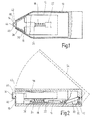
- Im folgenden wird die Erfindung anhand eines in der Zeichnung in schematischer Weise dargestellten Ausführungsbeispiels näher erläutert. Es zeigen
- Fig. 1
- ein stoßgeschützes Blutzuckermessgerät für Diabetiker in teilweise geschnittener Breitseitenansicht;
- Fig. 2
- das Blutzuckermessgerät in einem zu
Fig. 1 senkrechten Längsschnitt; - Fig. 3
- eine weitere Ausführungsform eines Blutzuckermessgeräts mit einer Verschlussvorrichtung in einer Öffnungs- und Schließstellung;
- Fig. 4
- das Blutzuckermessgerät bei geöffneter Verschlussvorrichtung zur Blutapplikation auf einem Testband in teilweise aufgebrochener Darstellung; und
- Fig. 5
- das Blutzuckermessgerät bei geschlossener Verschlussvorrichtung in einer
Fig. 4 entsprechenden Darstellung. - Das in der Zeichnung dargestellte Blutzuckermessgerät umfasst ein in der Hand aufnehmbares Gehäuse 10, eine darin eingesetzte Bandkassette 12 mit Testband 14, eine optisch arbeitende Detektionseinheit 16 zur Analyse von auf dem Testband appliziertem Blut sowie ein federelastisches Rückstellelement 18 und/oder eine Abdeck- bzw. Verschlussvorrichtung 20 als Aufprallschutz.
- Wie in
Fig. 1 dargestellt, ist das Rückstellelement 18 durch eine Schraubendruckfeder gebildet, die mit ihren Federenden zwischen einer gehäusefesten Abstützung 22 und einem Ausleger 24 der Detektionseinheit 16 in der Gerätelängsachse vorgespannt ist. Die Rückstellkraft der Schraubendruckfeder 18 wirkt dabei so, dass die Detektionseinheit 16 und die Bandeinheit 12 über keilförmige Anschlagflächen 26, 28 gegeneinander und gegen das Gehäuse 10 in definierter Anschlaglage gehalten sind. - Gemäß
Fig. 2 ist die Bandkassette 12 zum Auswechseln durch einen Freigabemechanismus 30 aus ihrer Anschlaglage lösbar. Der Freigabemechanismus 30 weist einen Kopplungshebel 32 auf, der an seinen Enden an einer Gehäuseklappe 34 und an einem Zughaken 36 angelenkt ist. Beim Aufschwenken der Gehäuseklappe 34 (gestrichelt inFig. 2 ) wird der Zughaken 36 zurückgezogen. Er greift dabei etwa auf halbem Rückzugweg in den Ausleger 24 der Detektionseinheit 16 ein und zieht diesen gegen die Kraft der Rückstellfeder zurück, so dass die Bandkassette 12 freikommt und entnommen werden kann. Bei geschlossener Gehäuseklappe 34 sorgt eine Blattfeder 38 dafür, dass die Bandkassette 12 auf der Detektionseinheit 16 und im Gehäuse 10 kraftschlüssig aufliegt. - In der in
Fig. 1 und 2 gezeigten Anschlaglage befinden sich die Bandkassette 12 und die Detektionseinheit 16 in einer Arbeitsstellung zur Messwerterfassung. Hierbei ragt ein spitz zulaufender Aufnahmekopf 40 der Bandkassette 12 aus einer Messöffnung 42 des Gehäuses 10 heraus und ermöglicht so eine dosierte Blutapplikation an der Aufnahmestelle 44 im Bereich seiner Spitze. Der Aufnahmekopf 40 bildet dabei eine Führung für das nach außen exponierte Testband 14, welches im Inneren der Bandkassette 12 über nicht gezeigte Wickelspulen abschnittsweise vorgespult wird. - Das Testband 14 weist eine Vielzahl von auf einem kontinuierlichen transparenten Trägerband im Abstand voneinander aufgebrachte Reagenzfelder auf, die durch entsprechenden Bandvorlauf sukzessive zum Einsatz gebracht werden und auf einen Analyten in einem aufgebrachten Blutstropfen durch eine Farbänderung ansprechen. Der Nachweis dieser Reaktion erfolgt durch reflexionsphotometrische Messung mittels der Optik 46 der Detektionseinheit 16, die in der Arbeitsstellung exakt auf Aufnahmestelle 44 fokussiert ist.
- Bei einer Stoßbelastung beispielsweise durch ungewolltes Fallenlassen des Geräts kann der Aufnahmekopf 40 in Kontakt mit der empfindlichen Detektionseinheit 16 gegen die Rückstellkraft der Schraubendruckfeder 18 in das Gehäuseinnere hinein ausweichen, so dass die Last im wesentlichen von dem stabilen Gehäuse 10 aufgenommen wird. Die Detektionseinheit 16 hat dabei gegenüber dem Zughaken 36 ausreichend Freiraum, um den Federweg nutzen zu können. Zudem besteht außerhalb der Anschlaglage in allen Freiheitsgraden ein begrenztes Bewegungsspiel bezüglich des Gehäuses, so dass auch ein nicht axial gerichteter Stoß günstig abgefangen werden kann. Zweckmäßig ist der Aufnahmekopf 40 beispielsweise als Federstahlführung elastisch verformbar ausgebildet, um anfängliche Kraftspitzen abzufedern.
- Wie nicht eigens dargestellt, können die Detektionseinheit 16 und die Bandkassette 12 auf einem Schlitten in dem Gehäuse linearbeweglich geführt sein. Als Antrieb kann der ohnehin erforderliche Wickelantrieb für das Testband genutzt werden, wobei die Drehbewegung über ein Getriebe in eine Linearbewegung des Schlittens umgesetzt wird.
- Bei den in
Fig. 3 bis 5 gezeigten Ausführungsformen ist der Bereich der Aufnahmestelle 44 in der Öffnungsstellung der Verschlussvorrichtung 20 zur Blutapplikation beispielsweise aus einer Fingerkuppe 46 freigegeben (Fig. 4 ) und in der Schließstellung gegen äußere Krafteinwirkung abgeschirmt (Fig. 5 ). Zu diesem Zweck weist die Verschlussvorrichtung 20 zwei halbschalige Verschlussklappen 48 auf, welche um eine gemeinsame Drehachse 52 verschwenkbar sind. - Gemäß
Fig. 3 ist jede Verschlussklappe 48 über einen zugehörigen Federmechanismus 50 betätigbar. Dieser umfasst einen im Drehpunkt 54 am Gehäuse 10 angelenkten zweiarmigen Griffhebel 56, dessen Griffarm 58 in eine Griffmulde 60 des Gehäuses 10 ragt und dessen in das Geräteinnere abgewinkelter Stützarm 62 über eine Feder 64 am Gehäuse 10 abgestützt und über eine Stange 66 mit einer Verschlussklappe 48 verbunden ist. Unter der Federvorspannung wird die Verschlussklappe 48 in der Schließstellung gehalten, wie es inFig. 3 für die untere Gehäusehälfte gezeigt ist. Wird der Griffarm 58 manuell entgegen der Kraft der Feder 64 betätigt, so zieht die Stange 66 die Verschlussklappe 48 in die inFig. 3 oben gezeigte Öffnungsstellung auf. Auf diese Weise ist es möglich, dass die Schließstellung beim gewollten oder unbeabsichtigten Loslassen automatisch eingenommen wird. - Die in
Fig. 4 und 5 gezeigte Ausführungsform sieht elektrische Griffschalter 60 vor, die in der federbelasteten gedrückten Schaltstellung das Gerät aktivieren und dabei eine motorische Öffnung der Verschlussklappen 48 bewirken. Hierfür kann ein die Wickelspulen 62, 64 der Bandkassette 12 antreibender Bandantrieb 66 genutzt werden, welcher über geeignete Getriebemittel mit den Verschlussklappen 48 koppelbar ist. Im aktivierten Zustand wird das Gerät mit den Fingern 68 in einer Hand gehalten, während an einem Finger 46 der anderen Hand wie vorstehend beschrieben Blut aufgenommen und analysiert wird, wobei das Messergebnis über eine Anzeige 70 ablesbar ist. Beim Ablegen des Geräts werden die Verschlussklappen 48 über der Öffnung 42 automatisch geschlossen und somit die Aufnahmestelle 44 gegen eindringende Verunreinigungen abgeschirmt.
Claims (15)
- Handgerät zur Untersuchung einer Körperflüssigkeit, insbesondere tragbares Blutzuckermessgerät, mit einer Bandeinheit (12) zum abschnittsweisen Vorspulen eines Testbandes (14), einer Detektionseinheit (16) zur Messwerterfassung an den im Bereich einer Aufnahmestelle (44) mit Körperflüssigkeit beaufschlagten Testbandabschnitten, und einem Gehäuse (10) zur Aufnahme der Bandeinheit (12) und Detektionseinheit (16), dadurch gekennzeichnet, dass die Aufnahmestelle (44) durch eine Abdeckvorrichtung (20) in einer Schließstellung gegen äußere Einwirkung abgeschirmt und in einer Öffnungsstellung zur Applikation von Körperflüssigkeit freigegeben ist.
- Handgerät nach Anspruch 1, dadurch gekennzeichnet, dass die Abdeckvorrichtung (20) mindestens ein vorzugsweise als Klappe, Schieber oder Rollo ausgebildetes, gegenüber dem Gehäuse (10) bewegliches Verschlussteil (48) aufweist.
- Handgerät nach Anspruch 1 oder 2, dadurch gekennzeichnet, dass die Abdeckvorrichtung (20) zum Verschluss einer die Aufnahmestelle (44) begrenzenden Gehäuseöffnung (42) ausgebildet ist.
- Handgerät nach einem der Ansprüche 1 bis 3, dadurch gekennzeichnet, dass die Abdeckvorrichtung (20) bei einer Geräteaktivierung selbsttätig in die Öffnungsstellung bringbar ist.
- Handgerät nach einem der Ansprüche 1 bis 4, dadurch gekennzeichnet, dass durch einen beim Vorspulen des Testbandes (14) aktivierten Bandantrieb (66) zugleich die Abdeckvorrichtung (20) in die Öffnungsstellung bewegbar ist.
- Handgerät nach einem der Ansprüche 1 bis 5, dadurch gekennzeichnet, dass die Abdeckvorrichtung (20) bei manueller Gerätehandhabung in die Öffnungsstellung und beim Loslassen des Gehäuses (10) selbsttätig in die Schließstellung bringbar ist.
- Handgerät nach einem der Ansprüche 1 bis 6, dadurch gekennzeichnet, dass die Abdeckvorrichtung (20) einen vorzugsweise durch Betätigung von an dem Gehäuse (10) befindlichen Griffelementen ((56) in der Öffnungsstellung vorgespannten Federmechanismus (52) aufweist.
- Handgerät nach einem der Ansprüche 1 bis 7, gekennzeichnet durch ein Schaltelement zum selbsttätigen Einschalten einer geräteinternen Stromversorgung beim Öffnen der Abdeckvorrichtung (20).
- Handgerät nach einem der Ansprüche 1 bis 8, dadurch gekennzeichnet, dass die Bandeinheit (12) durch eine austauschbare Wechselkassette gebildet ist.
- Handgerät nach einem der Ansprüche 1 bis 9, dadurch gekennzeichnet, dass die Testbandabschnitte durch auf einem kontinuierlichen Trägerband abschnittsweise aufgebrachte, auf einen Inhaltsstoff der Körperflüssigkeit ansprechende Reagenzfelder gebildet sind.
- Handgerät nach einem der Ansprüche 1 bis 10, dadurch gekennzeichnet, dass die Bandeinheit (12) und/oder die Detektionseinheit (16) bei einer Stoßbelastung gegen ein nachgiebiges Rückstellelement (18) aus einer Arbeitsstellung gegenüber dem Gehäuse (10) auslenkbar sind.
- Handgerät nach Anspruch 11, dadurch gekennzeichnet, dass die Bandeinheit (12) und/oder die Detektionseinheit (16) von der Aufnahmestelle (44) weg in das Gehäuse (10) hinein auslenkbar sind.
- Handgerät nach Anspruch 11 oder 12, dadurch gekennzeichnet, dass die Bandeinheit (12) und die Detektionseinheit (16) über einen auf das Rückstellelement (18) einwirkenden Freigabemechanismus (30) aus einer gegenseitigen Anschlaglage lösbar sind.
- Handgerät nach einem der Ansprüche 1 bis 13, dadurch gekennzeichnet, dass die Bandeinheit (12) einen in der Arbeitsstellung aus dem Gehäuse (10) herausragenden Aufnahmekopf (40) zur gehäuseexternen Exposition des Testbandes (14) aufweist.
- Handgerät nach Anspruch 14, dadurch gekennzeichnet, dass der vorzugsweise aus Federstahl bestehende Aufnahmekopf (40) elastisch verformbar ausgebildet ist.
Applications Claiming Priority (2)
| Application Number | Priority Date | Filing Date | Title |
|---|---|---|---|
| DE10348283A DE10348283A1 (de) | 2003-10-17 | 2003-10-17 | Handgerät zur Untersuchung einer Körperflüssigkeit |
| EP04790236A EP1675505B1 (de) | 2003-10-17 | 2004-10-09 | Handgerät zur untersuchung einer körperflüssigkeit |
Related Parent Applications (2)
| Application Number | Title | Priority Date | Filing Date |
|---|---|---|---|
| EP04790236.6 Division | 2004-10-09 | ||
| EP04790236A Division EP1675505B1 (de) | 2003-10-17 | 2004-10-09 | Handgerät zur untersuchung einer körperflüssigkeit |
Publications (2)
| Publication Number | Publication Date |
|---|---|
| EP2481348A1 true EP2481348A1 (de) | 2012-08-01 |
| EP2481348B1 EP2481348B1 (de) | 2016-12-21 |
Family
ID=34428457
Family Applications (2)
| Application Number | Title | Priority Date | Filing Date |
|---|---|---|---|
| EP12161995.1A Expired - Lifetime EP2481348B1 (de) | 2003-10-17 | 2004-10-09 | Handgerät zur Untersuchung einer Körperflüssigkeit |
| EP04790236A Expired - Lifetime EP1675505B1 (de) | 2003-10-17 | 2004-10-09 | Handgerät zur untersuchung einer körperflüssigkeit |
Family Applications After (1)
| Application Number | Title | Priority Date | Filing Date |
|---|---|---|---|
| EP04790236A Expired - Lifetime EP1675505B1 (de) | 2003-10-17 | 2004-10-09 | Handgerät zur untersuchung einer körperflüssigkeit |
Country Status (6)
| Country | Link |
|---|---|
| US (2) | US7758808B2 (de) |
| EP (2) | EP2481348B1 (de) |
| JP (1) | JP2007508079A (de) |
| CA (1) | CA2542468A1 (de) |
| DE (1) | DE10348283A1 (de) |
| WO (1) | WO2005034740A2 (de) |
Families Citing this family (13)
| Publication number | Priority date | Publication date | Assignee | Title |
|---|---|---|---|---|
| IL162842A0 (en) * | 2004-07-04 | 2005-11-20 | Blue I Technologies Ltd | Indictor strip and a device for automatic testing of liquids |
| FI121698B (fi) | 2005-07-19 | 2011-03-15 | Ihq Innovation Headquarters Oy | Terveydenseurantalaite ja sensorikasetti terveydenseurantalaitetta varten |
| EP1760469A1 (de) * | 2005-09-01 | 2007-03-07 | F.Hoffmann-La Roche Ag | Testsystem zur Untersuchung von Körperflüssigkeiten mit einem drehbaren Optikelement |
| EP1801584A1 (de) * | 2005-12-24 | 2007-06-27 | F.Hoffmann-La Roche Ag | Analysesystem für Körperflüssigkeiten |
| EP1815785A1 (de) * | 2006-02-02 | 2007-08-08 | Bioception B.V.i.o. | Diagnosegerät in Form einer Kassette zur Diagnose von Flüssigkeit und deren Inhalt |
| EP1826705A1 (de) | 2006-02-25 | 2007-08-29 | F.Hoffmann-La Roche Ag | Analytisches Verbrauchsmittel und Anordnung zum Auslesen von Informationen |
| US8789756B2 (en) | 2006-02-25 | 2014-07-29 | Roche Diagnostics Operations, Inc. | Test element coding apparatuses, systems and methods |
| PL1873521T3 (pl) * | 2006-06-27 | 2012-02-29 | Hoffmann La Roche | Diagnostyczna kaseta z taśmą |
| EP2111786A1 (de) * | 2008-04-23 | 2009-10-28 | F. Hoffmann-Roche AG | Testsystem |
| EP2177914A1 (de) * | 2008-10-17 | 2010-04-21 | F. Hoffmann-Roche AG | Testbandeinheit und Testbandgerät |
| EP2835639B1 (de) | 2013-08-09 | 2020-01-01 | Roche Diabetes Care GmbH | Testbandvorrichtung und Betriebsverfahren |
| EP3123939B1 (de) | 2015-07-29 | 2019-10-09 | Roche Diagnostics GmbH | Medizinisches instrument mit einem verschluss zum abdichten einer teststreifenöffnung |
| NL2027918B1 (en) * | 2021-04-06 | 2022-10-19 | Priva Holding B V | Horticulture facility, comprising a water loop |
Citations (7)
| Publication number | Priority date | Publication date | Assignee | Title |
|---|---|---|---|---|
| US5228972A (en) * | 1988-05-27 | 1993-07-20 | Daikin Industries, Ltd. | Apparatus for measuring concentration of test substance in liquid |
| DE19819407A1 (de) * | 1998-04-30 | 1999-11-11 | Hendrik Priebs | Teststreifenbehälter für Messgeräte, die mit Einwegteststreifen arbeiten |
| DE19849539A1 (de) * | 1998-10-27 | 2000-05-04 | Simons Hans Juergen | Portables Blutzuckermeßgerät |
| WO2001023885A1 (en) * | 1999-09-27 | 2001-04-05 | Hypoguard Limited | Test device |
| WO2002100274A1 (en) * | 2001-06-08 | 2002-12-19 | Hoffmann-La Roche Ag | Bodily fluid sampling device and test media cassette to be used with such a device |
| EP2026242A1 (de) | 2007-08-17 | 2009-02-18 | Roland Dr. Habiger | Verfahren und Vorrichtung zur Datenerfassung und -übertragung |
| EP2028894A1 (de) | 2007-07-20 | 2009-02-25 | High Tech Computer Corp. | Verfahren zur Handhabung von Messberichten in einem drahtlosen Kommunikationssystem |
Family Cites Families (4)
| Publication number | Priority date | Publication date | Assignee | Title |
|---|---|---|---|---|
| DE4326339A1 (de) * | 1993-08-05 | 1995-02-09 | Boehringer Mannheim Gmbh | System zur Analyse von Probenflüssigkeiten |
| FR2710411B1 (fr) * | 1993-09-21 | 1995-11-17 | Asulab Sa | Dispositif de mesure pour capteurs multizones amovibles. |
| DE19902601A1 (de) * | 1999-01-23 | 2000-07-27 | Roche Diagnostics Gmbh | Verfahren und Vorrichtung zum Entnehmen analytischer Verbrauchsmittel aus einem Vorratsbehältnis |
| US7378270B2 (en) * | 2003-11-10 | 2008-05-27 | Sentec Scientific, Inc. | Device for analyte measurement |
-
2003
- 2003-10-17 DE DE10348283A patent/DE10348283A1/de not_active Withdrawn
-
2004
- 2004-10-09 EP EP12161995.1A patent/EP2481348B1/de not_active Expired - Lifetime
- 2004-10-09 EP EP04790236A patent/EP1675505B1/de not_active Expired - Lifetime
- 2004-10-09 CA CA002542468A patent/CA2542468A1/en not_active Abandoned
- 2004-10-09 WO PCT/EP2004/011311 patent/WO2005034740A2/de not_active Ceased
- 2004-10-09 JP JP2006534657A patent/JP2007508079A/ja active Pending
-
2006
- 2006-04-17 US US11/405,257 patent/US7758808B2/en not_active Expired - Lifetime
-
2010
- 2010-06-14 US US12/814,890 patent/US7879291B2/en not_active Expired - Lifetime
Patent Citations (7)
| Publication number | Priority date | Publication date | Assignee | Title |
|---|---|---|---|---|
| US5228972A (en) * | 1988-05-27 | 1993-07-20 | Daikin Industries, Ltd. | Apparatus for measuring concentration of test substance in liquid |
| DE19819407A1 (de) * | 1998-04-30 | 1999-11-11 | Hendrik Priebs | Teststreifenbehälter für Messgeräte, die mit Einwegteststreifen arbeiten |
| DE19849539A1 (de) * | 1998-10-27 | 2000-05-04 | Simons Hans Juergen | Portables Blutzuckermeßgerät |
| WO2001023885A1 (en) * | 1999-09-27 | 2001-04-05 | Hypoguard Limited | Test device |
| WO2002100274A1 (en) * | 2001-06-08 | 2002-12-19 | Hoffmann-La Roche Ag | Bodily fluid sampling device and test media cassette to be used with such a device |
| EP2028894A1 (de) | 2007-07-20 | 2009-02-25 | High Tech Computer Corp. | Verfahren zur Handhabung von Messberichten in einem drahtlosen Kommunikationssystem |
| EP2026242A1 (de) | 2007-08-17 | 2009-02-18 | Roland Dr. Habiger | Verfahren und Vorrichtung zur Datenerfassung und -übertragung |
Also Published As
| Publication number | Publication date |
|---|---|
| US7879291B2 (en) | 2011-02-01 |
| US7758808B2 (en) | 2010-07-20 |
| CA2542468A1 (en) | 2005-04-21 |
| WO2005034740A2 (de) | 2005-04-21 |
| US20100249567A1 (en) | 2010-09-30 |
| US20060233663A1 (en) | 2006-10-19 |
| DE10348283A1 (de) | 2005-05-12 |
| EP1675505A2 (de) | 2006-07-05 |
| WO2005034740A3 (de) | 2005-07-21 |
| EP1675505B1 (de) | 2012-12-19 |
| EP2481348B1 (de) | 2016-12-21 |
| JP2007508079A (ja) | 2007-04-05 |
Similar Documents
| Publication | Publication Date | Title |
|---|---|---|
| EP2481348B1 (de) | Handgerät zur Untersuchung einer Körperflüssigkeit | |
| EP1808128B1 (de) | Stechhilfe mit Wiederverwendungsschutz | |
| DE10208575C1 (de) | Blutanalysegerät zur Bestimmung eines Analyten | |
| DE60317997T2 (de) | Lanzette | |
| DE69926336T2 (de) | Lanzetten-Vorrichtung zum Erzeugen eines Schnittes vorherbestimmter Grösse | |
| EP1825257B1 (de) | Diagnosesystem zum ermitteln von stoffkonzentrationen in flüssigen proben | |
| DE10325699B3 (de) | System zur Analyse einer zu untersuchenden Probe und Verwendung eines solchen Systems | |
| DE60213055T2 (de) | Testvorrichtung mit Mitteln zum Aufbewahren und Dispensieren von diagnostischen Streifen | |
| DE60015625T2 (de) | Lanzette mit lösbarer Steckverbindung | |
| EP2306893B1 (de) | Testsystem | |
| DE10245721A1 (de) | Stechvorrichtung zur Verwendung bei der Entnahme einer Minimalmenge von Blut zu Analysezwecken | |
| EP2236082A1 (de) | Gerät zur Gewinnung und Analyse einer Blutprobe | |
| EP0714638A1 (de) | Applikationsgerät für Dentalmasse | |
| DE69611094T2 (de) | Identifiziereinrichtung für optische fasern mit verschiedenen grössen | |
| DE102004022757B4 (de) | Streifenauswerfer | |
| EP1929937A1 (de) | Vorrichtung und Verfahren zum Untersuchen von Körperflüssigkeiten | |
| EP1329338B1 (de) | Schreibgerät | |
| EP2427101B1 (de) | Testeinheit zum einsatz in einem testgerät und testsystem | |
| DE102012107747A1 (de) | Stechhilfe zur Gewinnung von Körperflüssigkeitsproben | |
| EP1042986B1 (de) | Biopsienadel, Nadelhalter und Biopsiesystem | |
| DE10022720B4 (de) | Blutentnahmegerät | |
| DE3142011C2 (de) | Meßuhr mit Auslöseeinrichtung | |
| AT411633B (de) | Vorrichtung zum reinigen der chip-checkkarten kontrollierenden elektrischen kontakte von bankomaten | |
| EP4164504A1 (de) | Biopsienadelvorrichtung | |
| EP0371381A2 (de) | Filtereinrichtung für ein Bestrahlungsgerät |
Legal Events
| Date | Code | Title | Description |
|---|---|---|---|
| PUAI | Public reference made under article 153(3) epc to a published international application that has entered the european phase |
Free format text: ORIGINAL CODE: 0009012 |
|
| AC | Divisional application: reference to earlier application |
Ref document number: 1675505 Country of ref document: EP Kind code of ref document: P |
|
| AK | Designated contracting states |
Kind code of ref document: A1 Designated state(s): AT BE BG CH CY CZ DE DK EE ES FI FR GB GR HU IE IT LI LU MC NL PL PT RO SE SI SK TR |
|
| 17P | Request for examination filed |
Effective date: 20130131 |
|
| 17Q | First examination report despatched |
Effective date: 20140509 |
|
| GRAP | Despatch of communication of intention to grant a patent |
Free format text: ORIGINAL CODE: EPIDOSNIGR1 |
|
| RAP1 | Party data changed (applicant data changed or rights of an application transferred) |
Owner name: ROCHE DIABETES CARE GMBH Owner name: F. HOFFMANN-LA ROCHE AG |
|
| INTG | Intention to grant announced |
Effective date: 20160701 |
|
| GRAS | Grant fee paid |
Free format text: ORIGINAL CODE: EPIDOSNIGR3 |
|
| GRAA | (expected) grant |
Free format text: ORIGINAL CODE: 0009210 |
|
| AC | Divisional application: reference to earlier application |
Ref document number: 1675505 Country of ref document: EP Kind code of ref document: P |
|
| AK | Designated contracting states |
Kind code of ref document: B1 Designated state(s): AT BE BG CH CY CZ DE DK EE ES FI FR GB GR HU IE IT LI LU MC NL PL PT RO SE SI SK TR |
|
| REG | Reference to a national code |
Ref country code: GB Ref legal event code: FG4D Free format text: NOT ENGLISH |
|
| REG | Reference to a national code |
Ref country code: CH Ref legal event code: EP |
|
| REG | Reference to a national code |
Ref country code: IE Ref legal event code: FG4D Free format text: LANGUAGE OF EP DOCUMENT: GERMAN |
|
| REG | Reference to a national code |
Ref country code: AT Ref legal event code: REF Ref document number: 854735 Country of ref document: AT Kind code of ref document: T Effective date: 20170115 |
|
| REG | Reference to a national code |
Ref country code: DE Ref legal event code: R096 Ref document number: 502004015429 Country of ref document: DE |
|
| REG | Reference to a national code |
Ref country code: NL Ref legal event code: MP Effective date: 20161221 |
|
| PG25 | Lapsed in a contracting state [announced via postgrant information from national office to epo] |
Ref country code: GR Free format text: LAPSE BECAUSE OF FAILURE TO SUBMIT A TRANSLATION OF THE DESCRIPTION OR TO PAY THE FEE WITHIN THE PRESCRIBED TIME-LIMIT Effective date: 20170322 Ref country code: SE Free format text: LAPSE BECAUSE OF FAILURE TO SUBMIT A TRANSLATION OF THE DESCRIPTION OR TO PAY THE FEE WITHIN THE PRESCRIBED TIME-LIMIT Effective date: 20161221 |
|
| PG25 | Lapsed in a contracting state [announced via postgrant information from national office to epo] |
Ref country code: FI Free format text: LAPSE BECAUSE OF FAILURE TO SUBMIT A TRANSLATION OF THE DESCRIPTION OR TO PAY THE FEE WITHIN THE PRESCRIBED TIME-LIMIT Effective date: 20161221 |
|
| PG25 | Lapsed in a contracting state [announced via postgrant information from national office to epo] |
Ref country code: NL Free format text: LAPSE BECAUSE OF FAILURE TO SUBMIT A TRANSLATION OF THE DESCRIPTION OR TO PAY THE FEE WITHIN THE PRESCRIBED TIME-LIMIT Effective date: 20161221 |
|
| PG25 | Lapsed in a contracting state [announced via postgrant information from national office to epo] |
Ref country code: SK Free format text: LAPSE BECAUSE OF FAILURE TO SUBMIT A TRANSLATION OF THE DESCRIPTION OR TO PAY THE FEE WITHIN THE PRESCRIBED TIME-LIMIT Effective date: 20161221 Ref country code: RO Free format text: LAPSE BECAUSE OF FAILURE TO SUBMIT A TRANSLATION OF THE DESCRIPTION OR TO PAY THE FEE WITHIN THE PRESCRIBED TIME-LIMIT Effective date: 20161221 Ref country code: EE Free format text: LAPSE BECAUSE OF FAILURE TO SUBMIT A TRANSLATION OF THE DESCRIPTION OR TO PAY THE FEE WITHIN THE PRESCRIBED TIME-LIMIT Effective date: 20161221 Ref country code: CZ Free format text: LAPSE BECAUSE OF FAILURE TO SUBMIT A TRANSLATION OF THE DESCRIPTION OR TO PAY THE FEE WITHIN THE PRESCRIBED TIME-LIMIT Effective date: 20161221 |
|
| PG25 | Lapsed in a contracting state [announced via postgrant information from national office to epo] |
Ref country code: PL Free format text: LAPSE BECAUSE OF FAILURE TO SUBMIT A TRANSLATION OF THE DESCRIPTION OR TO PAY THE FEE WITHIN THE PRESCRIBED TIME-LIMIT Effective date: 20161221 Ref country code: BG Free format text: LAPSE BECAUSE OF FAILURE TO SUBMIT A TRANSLATION OF THE DESCRIPTION OR TO PAY THE FEE WITHIN THE PRESCRIBED TIME-LIMIT Effective date: 20170321 Ref country code: PT Free format text: LAPSE BECAUSE OF FAILURE TO SUBMIT A TRANSLATION OF THE DESCRIPTION OR TO PAY THE FEE WITHIN THE PRESCRIBED TIME-LIMIT Effective date: 20170421 Ref country code: ES Free format text: LAPSE BECAUSE OF FAILURE TO SUBMIT A TRANSLATION OF THE DESCRIPTION OR TO PAY THE FEE WITHIN THE PRESCRIBED TIME-LIMIT Effective date: 20161221 |
|
| REG | Reference to a national code |
Ref country code: FR Ref legal event code: PLFP Year of fee payment: 14 Ref country code: DE Ref legal event code: R097 Ref document number: 502004015429 Country of ref document: DE |
|
| PLBE | No opposition filed within time limit |
Free format text: ORIGINAL CODE: 0009261 |
|
| STAA | Information on the status of an ep patent application or granted ep patent |
Free format text: STATUS: NO OPPOSITION FILED WITHIN TIME LIMIT |
|
| 26N | No opposition filed |
Effective date: 20170922 |
|
| PG25 | Lapsed in a contracting state [announced via postgrant information from national office to epo] |
Ref country code: DK Free format text: LAPSE BECAUSE OF FAILURE TO SUBMIT A TRANSLATION OF THE DESCRIPTION OR TO PAY THE FEE WITHIN THE PRESCRIBED TIME-LIMIT Effective date: 20161221 |
|
| PG25 | Lapsed in a contracting state [announced via postgrant information from national office to epo] |
Ref country code: SI Free format text: LAPSE BECAUSE OF FAILURE TO SUBMIT A TRANSLATION OF THE DESCRIPTION OR TO PAY THE FEE WITHIN THE PRESCRIBED TIME-LIMIT Effective date: 20161221 |
|
| PG25 | Lapsed in a contracting state [announced via postgrant information from national office to epo] |
Ref country code: MC Free format text: LAPSE BECAUSE OF FAILURE TO SUBMIT A TRANSLATION OF THE DESCRIPTION OR TO PAY THE FEE WITHIN THE PRESCRIBED TIME-LIMIT Effective date: 20161221 |
|
| REG | Reference to a national code |
Ref country code: CH Ref legal event code: PL |
|
| REG | Reference to a national code |
Ref country code: IE Ref legal event code: MM4A |
|
| PG25 | Lapsed in a contracting state [announced via postgrant information from national office to epo] |
Ref country code: LU Free format text: LAPSE BECAUSE OF NON-PAYMENT OF DUE FEES Effective date: 20171009 Ref country code: CH Free format text: LAPSE BECAUSE OF NON-PAYMENT OF DUE FEES Effective date: 20171031 Ref country code: LI Free format text: LAPSE BECAUSE OF NON-PAYMENT OF DUE FEES Effective date: 20171031 |
|
| REG | Reference to a national code |
Ref country code: BE Ref legal event code: MM Effective date: 20171031 |
|
| PG25 | Lapsed in a contracting state [announced via postgrant information from national office to epo] |
Ref country code: BE Free format text: LAPSE BECAUSE OF NON-PAYMENT OF DUE FEES Effective date: 20171031 |
|
| REG | Reference to a national code |
Ref country code: FR Ref legal event code: PLFP Year of fee payment: 15 |
|
| PG25 | Lapsed in a contracting state [announced via postgrant information from national office to epo] |
Ref country code: IE Free format text: LAPSE BECAUSE OF NON-PAYMENT OF DUE FEES Effective date: 20171009 |
|
| REG | Reference to a national code |
Ref country code: AT Ref legal event code: MM01 Ref document number: 854735 Country of ref document: AT Kind code of ref document: T Effective date: 20171009 |
|
| PG25 | Lapsed in a contracting state [announced via postgrant information from national office to epo] |
Ref country code: AT Free format text: LAPSE BECAUSE OF NON-PAYMENT OF DUE FEES Effective date: 20171009 |
|
| PG25 | Lapsed in a contracting state [announced via postgrant information from national office to epo] |
Ref country code: HU Free format text: LAPSE BECAUSE OF FAILURE TO SUBMIT A TRANSLATION OF THE DESCRIPTION OR TO PAY THE FEE WITHIN THE PRESCRIBED TIME-LIMIT; INVALID AB INITIO Effective date: 20041009 |
|
| PG25 | Lapsed in a contracting state [announced via postgrant information from national office to epo] |
Ref country code: CY Free format text: LAPSE BECAUSE OF NON-PAYMENT OF DUE FEES Effective date: 20161221 |
|
| PG25 | Lapsed in a contracting state [announced via postgrant information from national office to epo] |
Ref country code: TR Free format text: LAPSE BECAUSE OF FAILURE TO SUBMIT A TRANSLATION OF THE DESCRIPTION OR TO PAY THE FEE WITHIN THE PRESCRIBED TIME-LIMIT Effective date: 20161221 |
|
| PGFP | Annual fee paid to national office [announced via postgrant information from national office to epo] |
Ref country code: IT Payment date: 20230920 Year of fee payment: 20 Ref country code: GB Payment date: 20230920 Year of fee payment: 20 |
|
| PGFP | Annual fee paid to national office [announced via postgrant information from national office to epo] |
Ref country code: FR Payment date: 20230920 Year of fee payment: 20 |
|
| PGFP | Annual fee paid to national office [announced via postgrant information from national office to epo] |
Ref country code: DE Payment date: 20230920 Year of fee payment: 20 |
|
| REG | Reference to a national code |
Ref country code: DE Ref legal event code: R071 Ref document number: 502004015429 Country of ref document: DE |
|
| REG | Reference to a national code |
Ref country code: GB Ref legal event code: PE20 Expiry date: 20241008 |
|
| PG25 | Lapsed in a contracting state [announced via postgrant information from national office to epo] |
Ref country code: GB Free format text: LAPSE BECAUSE OF EXPIRATION OF PROTECTION Effective date: 20241008 |
|
| PG25 | Lapsed in a contracting state [announced via postgrant information from national office to epo] |
Ref country code: GB Free format text: LAPSE BECAUSE OF EXPIRATION OF PROTECTION Effective date: 20241008 |