EP2480955B1 - Fernsteuerung von computern - Google Patents
Fernsteuerung von computern Download PDFInfo
- Publication number
- EP2480955B1 EP2480955B1 EP10818488.8A EP10818488A EP2480955B1 EP 2480955 B1 EP2480955 B1 EP 2480955B1 EP 10818488 A EP10818488 A EP 10818488A EP 2480955 B1 EP2480955 B1 EP 2480955B1
- Authority
- EP
- European Patent Office
- Prior art keywords
- hand
- image
- movement
- user
- computer device
- Prior art date
- Legal status (The legal status is an assumption and is not a legal conclusion. Google has not performed a legal analysis and makes no representation as to the accuracy of the status listed.)
- Active
Links
- 238000000034 method Methods 0.000 claims description 40
- 230000011218 segmentation Effects 0.000 claims description 35
- 230000003993 interaction Effects 0.000 claims description 28
- 238000001514 detection method Methods 0.000 claims description 25
- 230000008859 change Effects 0.000 claims description 15
- 210000003811 finger Anatomy 0.000 description 72
- 210000004247 hand Anatomy 0.000 description 19
- 210000003813 thumb Anatomy 0.000 description 17
- 238000010586 diagram Methods 0.000 description 16
- 230000001413 cellular effect Effects 0.000 description 10
- 238000004883 computer application Methods 0.000 description 8
- 238000004891 communication Methods 0.000 description 7
- 230000000737 periodic effect Effects 0.000 description 7
- 230000002596 correlated effect Effects 0.000 description 6
- 230000000007 visual effect Effects 0.000 description 5
- 238000013507 mapping Methods 0.000 description 3
- 230000003287 optical effect Effects 0.000 description 3
- 238000004458 analytical method Methods 0.000 description 2
- 239000002131 composite material Substances 0.000 description 2
- 230000000694 effects Effects 0.000 description 2
- 238000000605 extraction Methods 0.000 description 2
- 230000005057 finger movement Effects 0.000 description 2
- 238000010191 image analysis Methods 0.000 description 2
- 238000003703 image analysis method Methods 0.000 description 2
- 238000012986 modification Methods 0.000 description 2
- 230000004048 modification Effects 0.000 description 2
- 230000002093 peripheral effect Effects 0.000 description 2
- 101100127285 Drosophila melanogaster unc-104 gene Proteins 0.000 description 1
- 230000018199 S phase Effects 0.000 description 1
- 238000013459 approach Methods 0.000 description 1
- 238000003491 array Methods 0.000 description 1
- 230000008901 benefit Effects 0.000 description 1
- 230000000903 blocking effect Effects 0.000 description 1
- 238000004364 calculation method Methods 0.000 description 1
- 238000010276 construction Methods 0.000 description 1
- 230000001276 controlling effect Effects 0.000 description 1
- 238000005516 engineering process Methods 0.000 description 1
- 239000000463 material Substances 0.000 description 1
- 230000010363 phase shift Effects 0.000 description 1
- 238000012545 processing Methods 0.000 description 1
- 238000000926 separation method Methods 0.000 description 1
Images


Classifications
-
- G—PHYSICS
- G06—COMPUTING; CALCULATING OR COUNTING
- G06F—ELECTRIC DIGITAL DATA PROCESSING
- G06F3/00—Input arrangements for transferring data to be processed into a form capable of being handled by the computer; Output arrangements for transferring data from processing unit to output unit, e.g. interface arrangements
- G06F3/01—Input arrangements or combined input and output arrangements for interaction between user and computer
- G06F3/017—Gesture based interaction, e.g. based on a set of recognized hand gestures
-
- G—PHYSICS
- G06—COMPUTING; CALCULATING OR COUNTING
- G06F—ELECTRIC DIGITAL DATA PROCESSING
- G06F3/00—Input arrangements for transferring data to be processed into a form capable of being handled by the computer; Output arrangements for transferring data from processing unit to output unit, e.g. interface arrangements
- G06F3/002—Specific input/output arrangements not covered by G06F3/01 - G06F3/16
- G06F3/005—Input arrangements through a video camera
-
- G—PHYSICS
- G06—COMPUTING; CALCULATING OR COUNTING
- G06F—ELECTRIC DIGITAL DATA PROCESSING
- G06F3/00—Input arrangements for transferring data to be processed into a form capable of being handled by the computer; Output arrangements for transferring data from processing unit to output unit, e.g. interface arrangements
- G06F3/01—Input arrangements or combined input and output arrangements for interaction between user and computer
- G06F3/03—Arrangements for converting the position or the displacement of a member into a coded form
- G06F3/0304—Detection arrangements using opto-electronic means
-
- G—PHYSICS
- G06—COMPUTING; CALCULATING OR COUNTING
- G06F—ELECTRIC DIGITAL DATA PROCESSING
- G06F3/00—Input arrangements for transferring data to be processed into a form capable of being handled by the computer; Output arrangements for transferring data from processing unit to output unit, e.g. interface arrangements
- G06F3/01—Input arrangements or combined input and output arrangements for interaction between user and computer
- G06F3/03—Arrangements for converting the position or the displacement of a member into a coded form
- G06F3/033—Pointing devices displaced or positioned by the user, e.g. mice, trackballs, pens or joysticks; Accessories therefor
- G06F3/0346—Pointing devices displaced or positioned by the user, e.g. mice, trackballs, pens or joysticks; Accessories therefor with detection of the device orientation or free movement in a 3D space, e.g. 3D mice, 6-DOF [six degrees of freedom] pointers using gyroscopes, accelerometers or tilt-sensors
-
- G—PHYSICS
- G06—COMPUTING; CALCULATING OR COUNTING
- G06F—ELECTRIC DIGITAL DATA PROCESSING
- G06F3/00—Input arrangements for transferring data to be processed into a form capable of being handled by the computer; Output arrangements for transferring data from processing unit to output unit, e.g. interface arrangements
- G06F3/01—Input arrangements or combined input and output arrangements for interaction between user and computer
- G06F3/03—Arrangements for converting the position or the displacement of a member into a coded form
- G06F3/041—Digitisers, e.g. for touch screens or touch pads, characterised by the transducing means
- G06F3/042—Digitisers, e.g. for touch screens or touch pads, characterised by the transducing means by opto-electronic means
-
- G—PHYSICS
- G06—COMPUTING; CALCULATING OR COUNTING
- G06T—IMAGE DATA PROCESSING OR GENERATION, IN GENERAL
- G06T7/00—Image analysis
- G06T7/20—Analysis of motion
-
- G—PHYSICS
- G06—COMPUTING; CALCULATING OR COUNTING
- G06T—IMAGE DATA PROCESSING OR GENERATION, IN GENERAL
- G06T7/00—Image analysis
- G06T7/20—Analysis of motion
- G06T7/246—Analysis of motion using feature-based methods, e.g. the tracking of corners or segments
- G06T7/248—Analysis of motion using feature-based methods, e.g. the tracking of corners or segments involving reference images or patches
-
- G—PHYSICS
- G06—COMPUTING; CALCULATING OR COUNTING
- G06T—IMAGE DATA PROCESSING OR GENERATION, IN GENERAL
- G06T7/00—Image analysis
- G06T7/50—Depth or shape recovery
- G06T7/521—Depth or shape recovery from laser ranging, e.g. using interferometry; from the projection of structured light
-
- G—PHYSICS
- G06—COMPUTING; CALCULATING OR COUNTING
- G06T—IMAGE DATA PROCESSING OR GENERATION, IN GENERAL
- G06T7/00—Image analysis
- G06T7/50—Depth or shape recovery
- G06T7/55—Depth or shape recovery from multiple images
-
- G—PHYSICS
- G06—COMPUTING; CALCULATING OR COUNTING
- G06V—IMAGE OR VIDEO RECOGNITION OR UNDERSTANDING
- G06V20/00—Scenes; Scene-specific elements
- G06V20/40—Scenes; Scene-specific elements in video content
- G06V20/41—Higher-level, semantic clustering, classification or understanding of video scenes, e.g. detection, labelling or Markovian modelling of sport events or news items
-
- G—PHYSICS
- G06—COMPUTING; CALCULATING OR COUNTING
- G06V—IMAGE OR VIDEO RECOGNITION OR UNDERSTANDING
- G06V40/00—Recognition of biometric, human-related or animal-related patterns in image or video data
- G06V40/20—Movements or behaviour, e.g. gesture recognition
- G06V40/28—Recognition of hand or arm movements, e.g. recognition of deaf sign language
-
- H—ELECTRICITY
- H04—ELECTRIC COMMUNICATION TECHNIQUE
- H04N—PICTORIAL COMMUNICATION, e.g. TELEVISION
- H04N21/00—Selective content distribution, e.g. interactive television or video on demand [VOD]
- H04N21/40—Client devices specifically adapted for the reception of or interaction with content, e.g. set-top-box [STB]; Operations thereof
- H04N21/41—Structure of client; Structure of client peripherals
- H04N21/422—Input-only peripherals, i.e. input devices connected to specially adapted client devices, e.g. global positioning system [GPS]
- H04N21/42204—User interfaces specially adapted for controlling a client device through a remote control device; Remote control devices therefor
-
- G—PHYSICS
- G06—COMPUTING; CALCULATING OR COUNTING
- G06F—ELECTRIC DIGITAL DATA PROCESSING
- G06F3/00—Input arrangements for transferring data to be processed into a form capable of being handled by the computer; Output arrangements for transferring data from processing unit to output unit, e.g. interface arrangements
- G06F3/01—Input arrangements or combined input and output arrangements for interaction between user and computer
- G06F3/048—Interaction techniques based on graphical user interfaces [GUI]
- G06F3/0484—Interaction techniques based on graphical user interfaces [GUI] for the control of specific functions or operations, e.g. selecting or manipulating an object, an image or a displayed text element, setting a parameter value or selecting a range
- G06F3/04845—Interaction techniques based on graphical user interfaces [GUI] for the control of specific functions or operations, e.g. selecting or manipulating an object, an image or a displayed text element, setting a parameter value or selecting a range for image manipulation, e.g. dragging, rotation, expansion or change of colour
-
- G—PHYSICS
- G06—COMPUTING; CALCULATING OR COUNTING
- G06F—ELECTRIC DIGITAL DATA PROCESSING
- G06F3/00—Input arrangements for transferring data to be processed into a form capable of being handled by the computer; Output arrangements for transferring data from processing unit to output unit, e.g. interface arrangements
- G06F3/01—Input arrangements or combined input and output arrangements for interaction between user and computer
- G06F3/048—Interaction techniques based on graphical user interfaces [GUI]
- G06F3/0487—Interaction techniques based on graphical user interfaces [GUI] using specific features provided by the input device, e.g. functions controlled by the rotation of a mouse with dual sensing arrangements, or of the nature of the input device, e.g. tap gestures based on pressure sensed by a digitiser
- G06F3/0488—Interaction techniques based on graphical user interfaces [GUI] using specific features provided by the input device, e.g. functions controlled by the rotation of a mouse with dual sensing arrangements, or of the nature of the input device, e.g. tap gestures based on pressure sensed by a digitiser using a touch-screen or digitiser, e.g. input of commands through traced gestures
- G06F3/04883—Interaction techniques based on graphical user interfaces [GUI] using specific features provided by the input device, e.g. functions controlled by the rotation of a mouse with dual sensing arrangements, or of the nature of the input device, e.g. tap gestures based on pressure sensed by a digitiser using a touch-screen or digitiser, e.g. input of commands through traced gestures for inputting data by handwriting, e.g. gesture or text
-
- G—PHYSICS
- G06—COMPUTING; CALCULATING OR COUNTING
- G06T—IMAGE DATA PROCESSING OR GENERATION, IN GENERAL
- G06T2207/00—Indexing scheme for image analysis or image enhancement
- G06T2207/10—Image acquisition modality
- G06T2207/10016—Video; Image sequence
-
- G—PHYSICS
- G06—COMPUTING; CALCULATING OR COUNTING
- G06T—IMAGE DATA PROCESSING OR GENERATION, IN GENERAL
- G06T2207/00—Indexing scheme for image analysis or image enhancement
- G06T2207/10—Image acquisition modality
- G06T2207/10028—Range image; Depth image; 3D point clouds
-
- G—PHYSICS
- G06—COMPUTING; CALCULATING OR COUNTING
- G06T—IMAGE DATA PROCESSING OR GENERATION, IN GENERAL
- G06T2207/00—Indexing scheme for image analysis or image enhancement
- G06T2207/30—Subject of image; Context of image processing
- G06T2207/30196—Human being; Person
Definitions
- the present invention relates to control of computer devices and, more particularly, but not exclusively to a system and method for remote control of computer devices.
- Some of the currently used methods enable a computer user to control a computer device with a predefined gesture, using one or more body parts, such as the user's arms or legs.
- each gesture once detected, activates computer actions which are predefined for the specific gesture.
- the current methods typically include an initial set-up stage. In the set-up stage, there is defined a discrete set of gestures and computer functions for each specific gesture in the set.
- the gesture may be detected through a variety of currently used methods. For example, some of the current methods include regular image analysis from a digital video stream. The video images are analyzed to detect the dominant body part's location and position. If the body parts are aligned in a predefined position, the predefined function is carried out by the computer device.
- the detection of the body part is carried out by analysis of each pixel in the video image.
- the pixel is analyzed by a comparison made between the pixel's color values and values of other pixels in proximity to the pixel. That is to say that the regular image analysis methods depend on a significant difference in color between the body part and background objects.
- a depth map is an image that holds in each pixel the distance to the part of the object located in front of a depth camera.
- the depth map may be calculated using a variety of methods. For example, in stereovision methods, two or more cameras are used to capture images of the user's body. Images of an object captured from the cameras are compared and analyzed, to produce three dimensional data of depth location of each point on the surface of the user's body, thus yielding the depth map.
- stereovision methods two or more cameras are used to capture images of the user's body. Images of an object captured from the cameras are compared and analyzed, to produce three dimensional data of depth location of each point on the surface of the user's body, thus yielding the depth map.
- the user's body is lit from several directions.
- the shades of the body are compared and analyzed, to generate three dimensional data of the location of each point on the surface of the user's body, thus yielding the depth map.
- US 2009/0027337 A1 discloses a form of enhanced camera-based input, in which a detection region surrounding a user is defined in an image of a user within a scene and a position of an object (such as a hand) within the detection region is detected. Additionally, a control (such as a key of a virtual keyboard) in a user interface is interacted with based on the detected position of the object. Determining a user position may include analyzing a segmented camera image, where a camera image is segmented into foreground and background parts. Several exemplary approaches are described for producing segmented camera images.
- US 7,440,590 B1 discloses a method, system and code incorporating the steps of: projecting a composite image comprising a plurality of modulated structured light patterns at the object; capturing an image reflected from the surface; and recovering pattern information from the reflected image for each of the modulated structured light patterns.
- Pattern information is preferably recovered for each of the modulated structured light patterns used to create the composite by performing a demodulation of the reflected image. Reconstruction of the surface can be accomplished by using depth information from the recovered patterns to produce a depth map/mapping thereof.
- Applications of the depth mapping include: comparing the depth map with a plurality of stored depth map records of an animal feature, such as a face or hand, or of any other feature such as the distinguishing surface characteristic of a component being assembled, and so on, for purposes of identification or recognition of the object; or one may obtain orientation or positional data about the object from the depth map, such as roll, pitch and yaw angle data, or position data (co-ordinates for points or arrays) for use in connection with operation of a user-interaction interface for a wide variety of computerised devices.
- a computer readable medium storing computer executable instructions for performing steps of remote hand control of a computer device, the medium being defined in claim 15.
- Implementation of the method and system of the present invention involves performing or completing certain selected tasks or steps manually, automatically, or a combination thereof. Moreover, according to actual instrumentation and equipment of preferred embodiments of the method and system of the present invention, several selected steps could be implemented by hardware or by software on any operating system of any firmware or a combination thereof.
- selected steps of the invention could be implemented as a chip or a circuit.
- selected steps of the invention could be implemented as a plurality of software instructions being executed by a computer using any suitable operating system.
- selected steps of the method and system of the invention could be described as being performed by a data processor, such as a computing platform for executing a plurality of instructions.
- the present embodiments comprise an apparatus and a method, for remote hand control of a computer device.
- movement of a hand of a user of a computer device is continuously tracked.
- the user is presented a first image representative of the hand and a second image.
- the first image may be a full and accurately animated image of the user's hand, presented on a screen.
- the first image rather consists of five cursors, which represent the locations of the hand fingertips.
- the first image may also have any other visual appearance which gives the user information about the location of digits (i.e. fingers, thumb, or both) in relation to the second image, as described in further detail hereinbelow.
- the first image is moved in concert with the tracked movement. That is to say that the movement of the first image is correlated with the movement of the user's hand. If the user moves his hand to the left, the first image moves to the left. If the user flexes one of his fingers, the first image also flexes the finger (or moves the cursor representative of location of the finger's tip accordingly), etc.
- the second image is a graphical user interface (GUI) of a computer application such as a MicrosoftTM Excel spreadsheet with buttons and menu options, a web page with hyperlinks, buttons, etc.
- GUI graphical user interface
- the computer device is controlled according to interaction between the first image and the second image, as if the first image is the user's own hand, and the second image is a GUI presented on a touch screen which allows the user to interact with the GUI's menu, buttons, etc., by touching the touch screen with his own fingers.
- the user is allowed to control the computer device, by moving the user's hand or fingers, for bringing the first image and the second image into the interaction.
- the second image is rather an image representative of a computer input device (say a computer keyboard, a computer mouse, a joystick, etc., as known in the art).
- a computer input device say a computer keyboard, a computer mouse, a joystick, etc., as known in the art.
- the computer device is controlled according to interaction between the first image and the second image, as if the hand in the image is the user's own hand, and the second image is a real computer input device connected to the computer device like any standard peripheral computer device (say a keyboard, a joystick, etc).
- the user is thus allowed to control the computer device, by moving the user's hand, for bringing the first image and the second image into the interaction.
- the remote control of the computer device by movement of the user's hand, is a based on a continuous user interface, rather than on an interface limited to a predefined set of specific gestures (though specific gestures may also be defined).
- the computer device responds as if the user types using a real keyboard, as described in further detail hereinbelow.
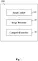
- FIG. 1 is a block diagram schematically illustrating an apparatus for remote hand control of a computer device, according to an exemplary embodiment of the present invention.
- Apparatus 1000 may be implemented on the computer device, be the computer device a desktop computer, a laptop computer, a cellular phone, etc.
- the apparatus 1000 may also be implemented on a device connectable to the computer device, say on a unit with a computer processor in communication with the computer device. Further, the apparatus 1000 may be implemented as software, as hardware, or as a combination of software and hardware.
- the apparatus 1000 includes a hand tracker 110.
- the hand tracker 110 tracks movement of a hand of a user of the computer device, say using images of the hand projected with light structured in a pattern useful for tracking fine movement of fingers and thumbs, as described in further detail hereinbelow.
- the hand tracker 110 is remote from the computer device, as described in further detail hereinbelow.
- the apparatus 1000 further includes an image presenter 120, in communication with the hand tracker 110.
- the image presenter 120 presents a first image representative of the hand and a second image.
- the second image is a graphical user interface (GUI) of a computer application such as a MicrosoftTM Excel spreadsheet with buttons and menu options, a web page with hyperlinks, buttons, etc.
- GUI graphical user interface
- the second image is rather representative of a computer input device say a computer mouse or a computer keyboard, as described in further detail hereinbelow.
- the second image is another graphical object, a picture, etc.
- the first image may be a full and accurately animated image of the user's hand, presented on the screen.
- the first image rather consists of five cursors, which represent the locations of the hand's fingertips.
- the first image may also have any other visual appearance which gives the user information about the location of digits (i.e. fingers, thumb, or both) in relation to the second image.
- the image presenter 120 further moves the first image in concert with the user hand movement tracked by the hand tracker 110, as described in further detail hereinbelow.
- Apparatus 1000 further includes a computer controller 130, in communication with the image presenter 120.
- the computer controller 130 is a part of a desktop computer, a laptop computer, etc., as described in further detail hereinbelow.
- the computer controller 130 is a part of a device installed in a car, as described in further detail hereinbelow.
- the computer controller 130 is a part of a cellular phone (say a smart phone), as described in further detail hereinbelow.
- the computer controller 130 controls the computer device in accordance with an interaction between the first image and the second image. Consequently, the computer controller 130 allows the user to control the computer device, by moving the hand for bringing the first image and the second image into the interaction, as described in further detail hereinbelow.
- the image presenter 120 moves the first image over an image of a computer keyboard. If the user moves his fingers in a typing movement, the computer controller 130 controls the computer device, making the computer device respond as if the user types using a real keyboard, as described in further detail hereinbelow.
- the image presenter 120 moves the first image over an image of a computer mouse. If the user moves his fingers in a clicking movement, the fingers of the first image move in a clicking movement accurately correlated with the movement of the hand's movement. Consequently, the computer device responds as if the user clicks on one of the buttons of a real computer mouse, according to position of the first image in relation to the image of the computer mouse (i.e. with the fingers of the first image positioned over the button of the computer mouse in the image).
- the second image is a graphical user interface (GUI) of a computer application such as a MicrosoftTM Excel spreadsheet with buttons and menu options, a web page with hyperlinks, buttons, etc.
- GUI graphical user interface
- the computer controller 130 controls the computer device according to interaction between the first image and the second image.
- the computer device is controlled, as if the first image is the user's own hand, and the second image is the GUI presented on a touch screen which allows the user to interact with the GUI's menu, buttons, etc., by touching the touch screen with his fingers.
- the hand tracker 110 uses bi-dimensional video data, for tracking the movement of the hand, say bi-dimensional video images streamed from a camera connected to the hand tracker 110, as described in further detail hereinbelow.
- the hand tracker 110 tracks the movement by detecting a segmentation (i.e. division) of a continuous feature in a light pattern projected onto the hand.
- the light pattern has the continuous feature in a first direction, and a non-continuous (say periodic) feature in a direction substantially perpendicular to the first direction, as described in further detail hereinbelow.
- the light pattern includes several stripes arranged in parallel (or in near parallel) to each other.
- the hand tracker 110 may identify in the light pattern, one or more clusters of one or more stripe segments created by segmentation of stripes by a digit of the hand (i.e. a finger or a thumb), as described in further detail hereinbelow.
- the hand tracker 110 tracks movement of the digit, by tracking the cluster of stripe segments created by segmentation of stripes by the digit, or by tracking at least one of the cluster's segments.
- the hand tracker 110 identifies in the light pattern, one or more clusters of one or more stripe segments created by segmentation of stripes by a palm of the hand.
- the hand tracker 110 tracks movement of the hand, by tracking the cluster of stripe segments created by segmentation of stripes by the palm, or by tracking at least one of the cluster's segments.
- the hand tracker 110 may further detect a shift in position of a notation along a continuous feature in the light pattern projected onto the hand.
- the hand tracker 110 uses the detected shift, in the tracking of the hand, as described in further detail hereinbelow.
- the hand tracker 110 further identifies a depth movement of the digit (say a movement similar to clicking or a touch screen like operation), as described in further detail hereinbelow.
- the apparatus 1000 further includes a light projector and a camera, in communication with the hand tracker 110, as described in further detail hereinbelow.
- the light projector, the camera, or both are remote from the computer device, as described in further detail hereinbelow.
- the light projector includes a source of light and a micro structured element, as known in the art.
- the source of light may a laser diode, a light emitting diode (LED), any another element which emits a light beam, as known in the art.
- LED light emitting diode
- the light beam emitted by the light source propagates through the micro structured element, onto the user's hand.
- the micro structured element modifies the light beam, for generating the light pattern projected onto the use's hand, as described in further detail hereinbelow.
- the micro structured element converts the light beam into a light beam of a variable cross sectional intensity profile. Consequently, the cross sectional intensity profile varies along the light beam, thus providing information indicative of a distance of an object (say one of the user's digits) from the source of light, as described in further detail hereinbelow.
- the light projector projects a light pattern having a continuous feature in a first direction and a non-continuous feature in a direction substantially perpendicular to the first direction, onto the hand, as described in further detail hereinbelow.
- the micro structured element is a diffractive optical element, as known in the art.
- the diffractive optical element may be obtained by a periodic micro structure that splits the light beam into a discrete number of spots having a one dimensional or a two dimensional spatial arrangement, as known in the art.
- an additional element such as a cylindrical micro lens array or an additional diffractive element is used to create a stripe from each of the spots.
- the stripe is marked with phase notations positioned in fixed distances from each other, along the stripe, as described in further detail hereinbelow.
- a possible advantage of using an additional microstructure element such as a cylindrical micro lens array is that the additional element may disperse a zero order of a light beam such as a laser beam, as known in the art.
- the zero order is a center of a light spot output from the diffractive element, and may be characterized by relatively high energy. Dispersing the zero order to a light structure such as the stripe, may allow increasing intensity of a laser light beam without crossing eye safety limits.
- the light projector further includes an additional diffractive element, which changes the cross-sectional intensity profile of each stripe in the light pattern with respect to the distance from an object which reflects the projected stripe.
- the cross-sectional intensity profile is an intensity profile perpendicular to the propagation direction of the light projected.
- the intensity profile change is a gradual change from a Gaussian cross-sectional intensity profile to a Top Hat cross-sectional intensity profile, carried out gradually along a distance traversed by the projected light, as the projected light propagates to an object, and is reflected back from surface of the object.
- the intensity profile change is a gradual change from an intensity profile with a single peak to an intensity profile with two or more peaks, etc., as known in the art.
- the change in the intensity profile, along distance traversed by light reflected from an object projected by the light with the light pattern, may help differentiate between stripes reflected from different objects, in different ranges, and thus further help overcome a segment unification problem, as discussed in further detail hereinbelow.
- the change in the intensity profile may further be used to directly measure distance to the object (say to the user's hand, fingers and thumb).
- the camera may be a video camera such as a webcam or a cellular phone's camera, positioned next to the light projector.
- the camera captures one or more image of the hand projected with the light pattern, and forwards the captured images to the hand tracker 110.
- the hand tracker 110 uses the captured images for tracking the movement of the hand, as described in further detail hereinbelow.
- the apparatus 1000 further includes a gesture recognizer, in communication with the hand tracker 110.
- the gesture recognizer detects in the tracked movement of the hand, a gesture predefined by an administrator of the apparatus 1000. Upon the detection of the gesture, the computer controller 130 controls the computer device in a manner predefined for the detected gesture, as described in further detail hereinbelow.
- the image presenter 120 aligns the first image into a predefined position. In one example, if the user shakes his hand, the image presenter 120 aligns the first image into a central position over the second image (say the computer keyboard image).
- the image presenter 120 resizes the first image (i.e. hand image), as described in further detail hereinbelow.
- FIG. 2 is a flowchart illustrating a method for remote hand control of a computer device, according to an exemplary embodiment of the present invention.
- An exemplary method according to an exemplary embodiment of the present invention may be implemented on the computer device, be the computer device a desktop computer, a laptop computer, a cellular phone, etc.
- the exemplary method may also be implemented on a device connectable to the computer device, say on a unit with a computer processor in communication with the computer device, as described in further detail hereinabove.
- the exemplary method there is tracked 210 movement of a hand of a user of the computer device, say using images of the hand projected with light structured in a pattern useful for tracking fine movement of fingers and thumbs, as described in further detail hereinbelow.
- the movement is tracked using the hand tracker 110, as described in further detail hereinabove.
- a first image representative of the hand and a second image to the user are presented 220 .
- the second image and the first image are presented to the user by the image presenter 120, as described in further detail hereinabove.
- the second image is a graphical user interface (GUI) of a computer application such as a MicrosoftTM Excel spreadsheet with buttons and menu options, a web page with hyperlinks, buttons, etc.
- GUI graphical user interface
- the second image is rather representative of a computer input device, say a keyboard or a computer mouse, as described in further detail hereinbelow.
- the second image is another graphical object, a picture, etc.
- the first image may be a full and accurately animated image of the user's hand, presented on the screen.
- the first image rather consists of five cursors, which represent the locations of the hand's fingertips.
- the first image may also have any other visual appearance which gives the user information about the location of digits (i.e. fingers and thumb) in relation to the second image.
- the first image is moved in concert with the user hand movement tracked 210 by the hand tracker 110, as described in further detail hereinbelow.
- the computer device is controlled 230, say by the computer controller 130, in accordance with an interaction between the first image and the second image.
- the user is allowed to control the computer device, by moving the hand for bringing the first image and the second image into the interaction, as described in further detail hereinbelow.
- the first image is moved over an image of a computer keyboard.
- the computer device is controlled 230, to make the computer device respond as if the user types using a real keyboard wired to the computer device, as described in further detail hereinbelow.
- the first image is moved over an image of a computer mouse.
- the computer device responds as if the user clicks on a button of a real computer mouse, according to position of the first image in relation to the image of the computer mouse (i.e. with the fingers of the first image positioned over the button of the computer mouse in the second image).
- the second image is a graphical user interface (GUI) of a computer application such as a MicrosoftTM Excel spreadsheet with buttons and menu options, a web page with hyperlinks, buttons, etc.
- GUI graphical user interface
- the computer device is controlled 230 (say by the computer controller 130), according to interaction between the images.
- the computer device is controlled 230, as if the first image is the user's own hand, and the second image is a GUI presented on a touch screen which allows the user to interact with the GUI's menu, buttons, etc., by touching the touch screen with his fingers.
- the tracking 210 of the movement of the hand is carried out using bi-dimensional video data (say bi-dimensional video images streamed from a camera connected to the hand tracker 110), as described in further detail hereinabove.
- the movement is tracked 210, by detecting a segmentation (i.e. division) of a continuous feature in a light pattern projected onto the hand.
- the light pattern has the continuous feature in a first direction, and a non-continuous (say periodic) feature in a direction substantially perpendicular to the first direction, as described in further detail hereinbelow.
- the light pattern includes several stripes arranged in parallel (or in near parallel) to each other.
- one or more clusters of one or more stripe segments created by segmentation of stripes by a digit of the hand i.e. a finger or a thumb
- the movement of the digit is tracked 210, by tracking the cluster of stripe segments created by segmentation of stripes by the digit, or by tracking at least one of the cluster's segments.
- a depth movement of the digit say a movement similar to a clicking or a touch screen like operation
- detecting a change in the number of segments in the tracked cluster as described in further detail hereinbelow.
- the hand tracker 110 there is further detected a shift in position of a notation along a continuous feature in the light pattern projected onto the hand.
- the detected shift is used in the tracking 210 of the hand, say by the hand tracker 110, as described in further detail hereinbelow.
- the exemplary method further includes detecting a gesture predefined by an administrator of the apparatus 1000, in the tracked 210 movement of the hand.
- the computer device is controlled 230 in a manner predefined for the detected gesture (say by the computer controller 130), as described in further detail hereinbelow.
- the first image is aligned into a predefined position.
- the image presenter 120 aligns the first image into a central position over the second image (say the computer keyboard image or the GUI).
- the first image is resized (say by the image presenter 120), as described in further detail hereinbelow.
- FIG. 3 is a block diagram schematically illustrating a computer readable medium storing computer executable instructions for performing steps of remote hand control of a computer device, according to an exemplary embodiment of the present invention.
- a computer readable medium 3000 such as a CD-ROM, a USB-Memory, a Portable Hard Disk, a diskette, etc.
- the computer readable medium 3000 stores computer executable instructions, for performing steps of remote hand control of a computer device, according to an exemplary embodiment of the present invention.
- the computer executable instructions include a step of tracking 310 movement of a hand of a user of the computer device, say using images of the hand projected with light structured in a pattern useful for tracking fine movement of fingers and thumbs, as described in further detail hereinbelow.
- the computer executable instructions further include a step of presenting 320 a first image representative of the hand and a second image, to the user, say on screen of the computer device, as described in further detail hereinabove.
- the first image is further moved in concert with the user hand movement tracked 310, as described in further detail hereinbelow.
- the second image is a graphical user interface (GUI) of a computer application such as a MicrosoftTM Excel spreadsheet with buttons and menu options, a web page with hyperlinks, buttons, etc.
- GUI graphical user interface
- the second image is rather representative of a computer input device, say a keyboard or a computer mouse, as described in further detail hereinbelow.
- the second image is another graphical object, a picture, etc.
- the first image may be a full and accurately animated image of the user's hand, presented on a screen.
- the first image rather consists of five cursors, which represent the locations of the hand's fingertips.
- the first image may also have any other visual appearance which gives the user information about the location of digits (i.e. fingers, thumb, or both) in relation to the second image.
- the computer executable instructions further include a step in which the computer device is controlled 330, in accordance with an interaction between the first image and the second image.
- the user is allowed to control the computer device, by moving the hand for bringing the first image and the second image into the interaction, as described in further detail hereinbelow.
- the first image is moved over an image of a computer keyboard.
- the computer device is controlled 330, to make the computer device respond as if the user types using a real keyboard, as described in further detail hereinbelow.
- the first image is moved over an image of a computer mouse.
- the computer device responds as if the user clicks on one of the buttons of a real computer mouse, according to position of the first image in relation to the image of the computer mouse (i.e. with the fingers of the first image positioned over a button of the mouse in the second image).
- the second image is a graphical user interface (GUI) of a computer application such as a MicrosoftTM Excel spreadsheet with buttons and menu options, a web page with hyperlinks, buttons, etc.
- GUI graphical user interface
- the computer device is controlled according to interaction between the images, as if the first image is the user's own hand, and the second image is a GUI presented on a touch screen which allows the user to interact with the GUI's menu, buttons, etc., by touching the touch screen with his fingers.
- the tracking 310 of the movement of the hand is carried out using bi-dimensional video data (say bi-dimensional video images streamed from a camera), as described in further detail hereinabove.
- the movement is tracked 310, by detecting a segmentation (i.e. division) of a continuous feature in a light pattern projected onto the hand.
- the light pattern has the continuous feature in a first direction, and a non-continuous feature in a direction substantially perpendicular to the first direction, as described in further detail hereinbelow.
- the light pattern includes several stripes arranged in parallel (or in near parallel) to each other.
- the instructions further include identifying in the light pattern, one or more clusters of one or more stripe segments created by segmentation of stripes by a digit of the hand (i.e. a finger or a thumb), as described in further detail hereinbelow. Consequently, the movement of the digit may be tracked 310, by tracking the cluster of stripe segments created by segmentation of stripes by the digit, or by tracking at least one of the cluster's segments.
- the instructions further include identifying a depth movement of the digit, say by detecting a change in the number of segments in the tracked cluster, as described in further detail hereinbelow.
- the instructions include identifying in the light pattern, one or more clusters of one of more stripe segments created by segmentation of stripes by a palm of the hand. Consequently, the movement of the hand may be tracked 310, by tracking the cluster of stripe segments created by segmentation (i.e. division) of stripes by the palm, or by tracking at least one of the cluster's segments.
- the instructions further include detecting a shift in position of a notation along a continuous feature in the light pattern projected onto the hand.
- the detected shift is used for tracking 310 of the hand, as described in further detail hereinbelow.
- the instructions further include detecting a gesture predefined by an administrator, in the tracked 310 movement of the hand.
- the computer device is controlled 330 in a manner predefined for the detected gesture, as described in further detail hereinbelow.
- the instructions further include a step in which, upon detection of the predefined gesture, the first image is aligned into a predefined position.
- the first image is aligned into a central position over the second image (say the computer keyboard image or GUI).
- the instructions further include a step in which, upon detection of the predefined gesture, the first image is resized, as described in further detail hereinbelow.
- FIG. 4 schematically illustrates a hand projected with a light pattern, according to an exemplary embodiment of the present invention.
- the tracking of the movement of the hand is carried out, using a light pattern designed to enable detection of hand movement, such as fine movements of fingers and thumbs.
- the specifically designed light pattern allows the tracking of the movement, even in bi-dimensional video data, which unlike three dimensional depth map, does not provide for easy separation of the hands from the rest of the body, according to distance, as described in further detail hereinabove.
- the light pattern is specifically designed to track movement of the hand's digits in a bi-dimensional video data (say video images streamed from a regular video camera). More specifically, the light pattern may be designed to enable detection and tracking of digits (i.e. fingers and thumb) as well as palm, in the bi-dimensional video data, according to distortions of the pattern by the digits, as described in further detail hereinbelow.
- the light pattern has a continuous feature in a first direction (say the X-axis) and a non-continuous (say periodic) feature in a direction substantially perpendicular to the first direction (say the Y-axis).
- the light pattern includes several stripes arranged in parallel (or in near parallel) to each other, as illustrated schematically using Fig. 4 .
- a camera is positioned in a certain Y-axis distance, above a light projector which projects the stripes pattern on the hand 410 and on the background 420 (say a surface of a table the hand rests on, a wall, etc.).
- the position of the camera is selected, so as to create a triangulation effect between the camera, the light projector and the light reflected back from the user's hand 410 and the background 420, as known in the art.
- the triangulation effect causes discontinuities in the pattern at the points along a stripe where there are significant depth shifts from an object projected with a light pattern.
- the discontinuities segment (i.e. divide) the stripe into two or more stripe segments, say a segment 431 positioned on the hand, a segment 432 position to the left of the hand and a segment 433 position to the right of the hand.
- Such depth shift generated stripe segments may be located on the contours of the user's hand's palm or digits, which are positioned between the camera and the user's body.
- the user's digit or palm segments the stripe into two or more stripe segments.
- the hand tracker 110 may thus analyze bi-dimensional video data (say a video stream forwarded to the hand tracker 110 from the camera), to generate clusters of stripe segments.
- the hand tracker 110 may identify in the light pattern, a cluster of one or more stripe segments created by segmentation of stripes by a digit of the hand, say a cluster 441 of four segments reflected from the hand's central finger. Consequently, the hand tracker 110 tracks the movement of the digit, by tracking the cluster of stripe segments created by segmentation of stripes by the digit, or by tracking at least one of the cluster's segments.
- the cluster of stripe segments created by segmentation (i.e. division) of stripes by the digit includes strip segments with an overlap in the X axis.
- the stripe segments in the cluster further have similar lengths (derived from the fingers thickness) or relative proximity in the Y-axis coordinates.
- the segments may have a full overlap for a digit positioned straightly, or a partial overlap for a digit positioned diagonally in the X-Y plane.
- the hand tracker 110 further identifies a depth movement of the digit, say by detecting a change in the number of segments in the tracked cluster.
- the angle between the digit and the plane of the light projector and camera changes. Consequently, the number of segments in the cluster 441 is reduced from four to three.
- the hand tracker 110 identifies in the light pattern, one or more clusters of one or more stripe segments created by segmentation of stripes by a palm of the hand. Consequently, the movement of the hand is tracked 210, by tracking the cluster of stripe segments created by segmentation of stripes by the palm, or by tracking at least one of the cluster's segments.
- the cluster of stripe segments created by segmentation of stripes by the palm includes an upper strip segment 431 which overlaps with the user hand's fingers stripe segment clusters, in the X axis.
- the upper strip segment 431 overlaps the four finger clusters in the X-axis, but do not exceed beyond the minimum and maximum X value of the four finger clusters' bottom segments.
- the cluster of stripe segments created by segmentation of stripes by the palm further includes, just below segment 431, a few strip segments in significant overlap with the strip segment 431.
- the cluster of stripe segments created by segmentation of stripes by the palm further includes longer stripe segments that extend to the base of a stripe segment cluster 451 of the user's thumb.
- the digit and palm cluster's orientation may differ with specific hands positions and rotation.
- FIG. 5 schematically illustrates a hand projected with a light pattern having an intensity notation, according to an exemplary embodiment of the present invention.
- stripe segments reflected from background of the hand may unite with stripe segments reflected from the hand. Consequently, the stripe segment clusters of the palm and digits cannot be found, and the hands cannot be tracked.
- the notation is in a form of a light intensity 320, which changes along the stripe, or a specific shape that appears in a constant distance along the stripe, such as a short vertical line.
- the camera is positioned with respect to the light projector, with a gap in the X-axis, as well as the gap in the Y-axis discussed in further detail hereinabove.
- This gap in the X-axis creates a phase shift in the position of the notations along the stripes with respect to the object's distance.
- the segments still have different phases of the periodic notation.
- the ratio of the vertical and horizontal distances between the camera and the light projector is carefully selected, so as to maximize the notation's phase shift between the segments when the segments unite.
- a second way which may prove useful for overcoming the problem of the united segments is by changing the setup of the camera and light projector, so as to differ in their Z-axis positions too.
- a difference in Z-axis positioning between the camera and the light projector may be brought about either by physically positioning the camera and light projector in different Z-axis positions or by deployment of a negative or positive lens in front of the projected pattern at a certain distance.
- the stripe segments of the light pattern reflected from the object have different periods at different object distances. Therefore, even if one of the stripe segments reflected from the hand unites with a stripe segment reflected from the background, adjacent lines do not unite because of the different periods.
- a third way which may prove useful for overcoming the problem of the united segments, is carried out using a micro structured element, which converts the light beam into a light beam of a varying cross sectional intensity profile, as described in further detail hereinabove.
- the cross sectional intensity profile changes according to distance of an object which reflects the light pattern, from the light projector.
- a method according to an exemplary embodiment of the present invention may further include tracking of depth movement of the hand's digit, by detecting a vertical movement of the cluster of stripe segments created by segmentation of stripes by the digit, a horizontal movement of notations on the stripe segments, or both.
- the tracking of the depth movement of the digit is carried out by detecting a vertical movement of the uppermost segment in the cluster of stripe segments created by segmentation of stripes by the digit.
- the uppermost segment represents the tip of the digit, which performs the digit's most significant movement in the Z-Y plane.
- the tracking of the depth movement is carried out by detecting a change in number of segments in the tracked cluster. That is to that a depth movement of the hand finger (i.e. movement in the Z-axis) may cause one of the tracked stripe segments of the digit to move upwards and disappear, cause a new stripe segment to appear, etc.
- FIG. 6 is a block diagram schematically illustrating remote hand control of a computer device, using an image of a computer keyboard, according to an exemplary embodiment of the present invention.
- movement of a hand 610 of a user of a computer device is continuously tracked.
- the user is presented a first image 620 representative of the hand and a second image representative of a computer input device, say a computer keyboard, a computer mouse, a joystick, etc., as known in the art, on a screen.
- a computer input device say a computer keyboard, a computer mouse, a joystick, etc.
- the first image 620 may be a full and accurately animated image of the user's hand, presented on a screen.
- the first image 620 may consist of five cursors, which represent the locations of the hand's 610 fingertips.
- the first image 620 may also have any other visual appearance which gives the user information about the location of digits (i.e. fingers and thumb) in relation to a computer input device also displayed on the screen.
- the first image 620 is moved in concert with the tracked movement. That is to say that the movement of the first image 620 is correlated with the movement of the user's own hand 610. If the user moves his hand 610 to the left, the first image 620 moves to the left. If the user flexes one of his fingers, the first image 620 also flexes the finger, etc.
- the computer device is controlled according to interaction between the first image 620 and the second image, as if the hand in the image 620 is the user's own hand 610, and the input device is a real computer input device connected to the computer device.
- the computer input device may include, but is not limited to a standard peripheral computer device, such as a keyboard, a joystick, a computer mouse, etc.
- the user is thus allowed to remotely control the computer device, by moving the user's hand 610, for bringing the first image 620 and the second image into the interaction.
- the remote control of the computer device by movement of the user's hand 610, is based on a continuous user interface, rather than on an interface limited to a predefined set of specific gestures (though specific gestures may also be defined).
- the computer device responds as if the user types using a real keyboard, as described in further detail hereinbelow.
- the second finger of the first image 620 is just above the 'C' character on an image of a computer keyboard.
- the second finger of the first image 620 moves in parallel and presses the 'C' character of the keyboard image presented on the screen. Consequently, the computer device responds as if the 'C' character of a real keyboard wired to the computer device is pressed by the user, using the user's own finger.
- the absolute location of the user hands in a three dimensional space is not relevant, and only the movement of the user's fingers needs to be tracked.
- the movement of the first image 620 though accurately correlated with the movement of the user's own hand 610, may be carried out in a different scale. That is to say that the size of the first image 620 may differ from the size of the user's real hand 610.
- the gesture recognizer of apparatus 1000 further allows the user the resize the first image 620, as described in further detail hereinbelow.
- FIG. 7 is a block diagram schematically illustrating a first gesture for remote hand control of a computer device, according to an exemplary embodiment of the present invention.
- An apparatus may include a gesture recognizer, as described in further detail hereinabove.
- a first exemplary gesture is a reset gesture in which the user shakes his hand 710 in front of the camera (say by quick minor vibration of the fingers and hand in a lateral movement).
- the first image presented on the screen moves to a predefined position over the second image, say to a predefined position over a computer input device presented in the second image or to a position over a first line of a spreadsheet like graphical user interface presented on the screen.
- the image presenter 120 moves the first image into a position over a displayed computer keyboard's center, as described in further detail hereinabove.
- the exemplary reset gesture may further ease detection of a digit location, since the exemplary reset gesture comprises separate movement of each digit.
- FIG. 8 is a block diagram schematically illustrating a second gesture for remote hand control of a computer device, according to an exemplary embodiment of the present invention.
- a second exemplary gesture is a resize gesture, say a gesture in which the user turns is hand 810 in a predefined direction.
- the image presenter 120 changes the size of the first image displayed on the screen, without changing the second image in terms of size or zoom level.
- a user who interacts with an image of a keyboard displayed in a full screen mode may want to use a larger first image (say hand image), in order to get from one side of the keyboard to the other with a relatively small movement of his real hands (since the scale of movement depends on size of the hand image).
- the user may need a smaller first image (say hand image), for selecting a text with a small font on his web browser.
- the size of the first image i.e. hand image
- the image presenter 120 rather resizes the second image (say the keyboard), which shrinks, expands, zooms in or zooms out, thus changing the size proportion between the first image and the second image.
- FIG. 9 is a block diagram schematically illustrating a third gesture for remote hand control of a computer device, according to an exemplary embodiment of the present invention.
- a third exemplary gesture is a click (or a double click) gesture, say a gesture in which the user clicks 910 using one or two fingers of the user's hand.
- the image presenter 120 moves fingers of the first image in a clicking movement accurately coordinated with the movement of the user's fingers.
- the user may be presented an image of a computer mouse, and be allowed to move the first image into a position above the computer mouse in the image.
- the fingers of the first image click on the image of the computer mouse, and the computer controller 130, makes the computer device respond as if the user clicks on a real computer mouse with the user's own fingers.
- FIG. 10 is a block diagram schematically illustrating a fourth gesture for remote hand control of a computer device, according to an exemplary embodiment of the present invention.
- a fourth exemplary gesture is a zooming gesture, such as a gesture in which the user zooms in or simply magnifies an image presented on screen of a computer device, say by moving the user's hand 1010 in a pulling movement or by moving two of the user's fingers away from each other (similarly to movement of fingers away from each other on a touch screen of a smart phone).
- the image presenter 120 moves two fingers of the first image away from each other in parallel to the movement of the user's fingers.
- the computer controller 130 controls the computer device (say a cellular smart phone), for zooming in or magnifying the image presented on screen of the computer device, thus providing the user with a touch screen like functionality without having the user touch a real touch screen.
- Exemplary embodiment of the present invention provide for a variety of other user gestures, say a scrolling down gesture in which the user straitens his finger, or a scrolling up gesture in which the user moves his finger in the opposite direction.
- the gestured may be carried with one or two hands, one or more digits, hand and digits, etc.
- the remote control of the computer device by movement of the user's hand, is based on a continuous user interface, rather than on an interface limited to a predefined set of specific gestures (though specific gestures may also be defined).
- the remote control of the computer device may be based on a continuous interaction of the user with the image of the computer keyboard presented on screen of the computer device.
- the user is allowed to move his hand in the air, thus moving the first image over the keyboard, to move the user's digits in a typing movement, thus typing on the keyboard with the fingers of the first image, etc., as described in further detail hereinabove.
- the user moves his hand, for moving the first image through an interaction, in which the first image holds a computer mouse presented on screen, drags the mouse, etc.
- the computer device moves a cursor on screen, as if a real mouse is dragged by the user, using is own hand.
- the user is further allowed to cause the mouse to move automatically, by a single small middle finger movement. Consequently, the mouse moves automatically from one side of the screen to the other, or rather the mouse moves through a predefined distance or time (say for three seconds).
- GUI graphical user interface
- the computer device is controlled according to a continuous interaction between a hand image moving in concert with movement of a user's own hand and fingers, and the GUI's menu, buttons, etc., as if the user touches a touch screen which presents the GUI to the user, with the user's own fingers.
- FIG. 11 is a block diagram schematically illustrating a system for remote hand control of a computer device, according to an exemplary embodiment of the present invention.
- An exemplary system for remote hand control of a computer device includes the parts of apparatus 1000, as described in further detail hereinabove.
- one or more of the parts of the apparatus 1000 are installed on a mobile unit 1110.
- the mobile unit 1110 wirelessly communicates with other parts of the apparatus 1000, with the computer device 1120 (say a computer combined with a screen, like an AppleTM iMac computer, a TV set with a computer processor, etc.), or both.
- the computer device 1120 say a computer combined with a screen, like an AppleTM iMac computer, a TV set with a computer processor, etc.
- the user may place the mobile unit 1110 on a table.
- the user may sit on a chair next to the table, move his hands, and thereby control the computer device 1120.
- the user controls the computer device 1120, through an interaction of the first image (representative of the user's hand) with an image of a computer keyboard presented on a screen of the computer device 1120, as described in further detail hereinabove.
- the exemplary method and apparatus of the present invention may be used for additional applications.
- apparatus 1000 may enable the user to scroll, type text, zoom and click, without touching the cellular phone. Consequently, the cellular phone may be small, but may still allow interaction with the cellular phone, as if the phone has a full size computer keyboard.
- the cellular phone has a projector, which may project images on a wall.
- the user may move a first image projected next to an image of the phone's controller, be the controller a regular phone button or a touch screen.
- the user may bring the first image (say hand image) into interaction with the image of the phone's controller, thus operating the phone in accordance with the interaction, as if the user uses his own hand to operate the real phone controller directly.
- the computer device is a computer device installed in a car (say a GPS unit or a phone unit).
- the apparatus 1000 of the present embodiments may be installed on the car's computer device (or in communication with the car's computer device).
- the hand tracker 110 may track hand and finger movement of the driver, and thereby enable the driver to control the computer device (say the GPS or phone unit), without moving the driver's eyes from the road, to his fingers which operate the small buttons of the unit.
- the computer device say the GPS or phone unit
- an image of a hand and an image of the GPS or phone unit's keys are presented to the driver on a small screen installed on the cars front window, without significantly blocking sight through the window.
- the driver may click wherever he finds convenience, to actually dial the numbers or choose his destination in a guiding system of the GPS unit.
- the driver may control the GPS or phone unit, using his hand on an arbitrary area of the drive wheel, while looking through the front window on which the screen is installed, and keeping his eyes on the road.
- the driver may shake his hands in a reset movement, as described in further detail hereinabove. Consequently, the first image is positioned on center of an image of the car phone's numbers or the car's GPS unit touch screen buttons, present on the screen.
- the apparatus 1000 may also be installed on a musical instrument, say a synthesizer, a DJ turn table, or another musical instrument guided by hand movements of the user, as described in further detail hereinabove.
- a musical instrument say a synthesizer, a DJ turn table, or another musical instrument guided by hand movements of the user, as described in further detail hereinabove.
- Some methods include regular image analysis from a digital video stream.
- the video images are therefore analyzed to detect a specific area of interest, usually a body part such as a hand, a face, an arm, etc.
- body gestures may be detected and translated to control media displayed on a computer screen or TV.
- Detecting a body part such as the user's hand and fingers requires first to analyze each pixel in the image by its color values and to compare it to other pixels in its environment. Such a method may suffer from high computational time and from relatively high percentage of errors and false readings.
- One of the main difficulties comes from the background behind the hands needed to be detected.
- the method may have difficulties detecting the hands of a user that wears a shirt with a color that is close to his skin color or with another complex pattern.
- the lightning of the room affects also the detection performance.
- the angle of the hands towards the camera may be a difficulty in this method as well.
- the shape of the hand changes with the rotation of it and the fingertips may be on the same axis with the rest of the hand towards the camera, and therefore be not detectable by color difference.
- Other methods for hand detection and gesture recognition include using a 3D depth map.
- the depth map is an image that holds in each pixel the distance to the part of the object located in front of the depth camera, which is represented by the pixel.
- a depth solves many of the problems that exist in regular 2D video analysis. Extracting the hands location is relatively easy since they are usually located in front of the body and therefore can be separated by cutting out the parts of the image that exceed a certain distance. With such methods, the angle of the hands towards the camera is less significant in the same manner. The closest part of the hand or the body can be detected by just the distance, without considering the background color. However, acquiring a full 3D depth map requires a relatively complex hardware and computational effort.
- the full depth map of a human body may be significant for certain applications of gesture recognition such as gaming. For example, in a tennis game application it is important exactly how the user is located, if his hand is stretched back ready to hit the ball or stretched forward to block the ball near the net. However, other applications such as a gesture driven virtual keyboard or mouse may not have the need for full 3D depth mapping of hands and fingers, in order to control the applications.
- Image comparison based solutions may use structured light patterns such as a grid pattern in order to directly detect gestures.
- the comparison based solutions detect distortion in the grid pattern and compare the distortions to a pre defined set of distortions of the grid pattern that represent specific gestures. Once detected, the gestures activate computer actions which are attached to each gesture.
- the image comparison based solutions extract hand gestures directly for a captured light pattern image, they are limited to a discrete set of predefined gestures, and do not offer a flexible tracking and representation of the user hands and fingers, and the controlling of a computer device through a continuous user interface, as described in further detail hereinabove.
Claims (15)
- Einrichtung zur Handfernsteuerung einer Computervorrichtung (1120), wobei die Einrichtung Folgendes umfasst:einen Hand-Tracker (110), der zum Verfolgen einer Bewegung einer Hand (410; 610; 710; 810) eines Benutzers der Computervorrichtung (1120) konfiguriert ist;ein Bildpräsentationsgerät (120), das mit dem Hand-Tracker (110) assoziiert ist und zum Präsentieren eines ersten Bildes (620), das die Hand (410; 610; 710; 810) repräsentiert, und eines zweiten Bildes für den Benutzer und zum Bewegen des ersten Bildes (620) in Übereinstimmung mit der verfolgten Bewegung konfiguriert ist; undeine Computersteuerung (130), die mit dem Bildpräsentationsgerät (120) assoziiert ist und zum Steuern der Computervorrichtung (1120) gemäß einer Interaktion zwischen dem ersten Bild (620) und dem zweiten Bild konfiguriert ist, wodurch ermöglicht wird, dass der Benutzer die Computervorrichtung (1120) steuert, indem er die Hand bewegt, um eine Interaktion des ersten Bildes (620) und des zweiten Bildes hervorzurufen,wobei der Hand-Tracker (110) ferner zum Verfolgen der Bewegung der Hand konfiguriert ist, indem eine Segmentierung eines kontinuierlichen Merkmals in einem Lichtmuster nach Reflexion von der Hand (410; 610; 710; 810) detektiert wird, wobei das Lichtmuster, das auf die Hand (410; 610; 710; 810) projiziert wird, das kontinuierliche Merkmal in einer ersten Richtung und ein nichtkontinuierliches Merkmal in einer Richtung im Wesentlichen senkrecht zu der ersten Richtung aufweist, wobei der Hand-Tracker (110) ferner zum Verfolgen der Bewegung der Hand (410; 610; 710; 810) basierend auf einer Änderung eines Intensitätsprofils des Lichtmusters nach Reflexion von der Hand (410; 610; 710; 810) entlang der ersten Richtung konfiguriert ist, undwobei das Lichtmuster, das auf die Hand (410; 610; 710; 810) projiziert wird, mehrere Streifen umfasst, die im Wesentlichen parallel zueinander angeordnet sind,wobei der Hand-Tracker (110) ferner zum Identifizieren eines Clusters aus Streifensegmenten (431), das durch Segmentierung von Streifen durch eine Handfläche der Hand (410; 610; 710; 810) erzeugt wird, in dem Lichtmuster nach Reflexion von der Hand (410; 610; 710; 810) konfiguriert ist, undwobei der Hand-Tracker (110) ferner zum Verfolgen der Bewegung der Hand (410; 610; 710; 810) durch Verfolgen des Clusters aus Streifensegmenten (431) konfiguriert ist.
- Einrichtung nach Anspruch 1, wobei der Hand-Tracker (110) ferner zum Verwenden von bidimensionalen Videodaten zum Verfolgen der Bewegung der Hand (410; 610; 710; 810) konfiguriert ist.
- Einrichtung nach Anspruch 1, wobei der Hand-Tracker (110) ferner zum Identifizieren wenigstens eines Clusters (441, 451) aus Streifensegmenten (431), das durch Segmentierung von Streifen durch einen jeweiligen Finger der Hand (410; 610; 710; 810) erzeugt wird, in dem Lichtmuster nach Reflexion von der Hand (410; 610; 710; 810) und zum Verfolgen einer Bewegung des Fingers durch Verfolgen des wenigstens einen Clusters (441, 451) aus Streifensegmenten (431), das durch Segmentierung von Streifen durch den Finger erzeugt wird, konfiguriert ist.
- Einrichtung nach Anspruch 3, wobei der Hand-Tracker (110) ferner zum Identifizieren einer Tiefenbewegung des Fingers durch Detektieren einer Änderung der Anzahl an Streifensegmenten (431-433) in dem wenigstens einen verfolgten Cluster (441, 451) konfiguriert ist.
- Einrichtung nach Anspruch 1, wobei der Hand-Tracker (110) ferner zum Verfolgen der Bewegung durch Detektieren einer Verschiebung einer Position eines Kennzeichens entlang eines kontinuierlichen Merkmals in einem Lichtmuster nach Reflexion von der Hand (410; 610; 710; 810) konfiguriert ist.
- Einrichtung nach Anspruch 1, die ferner einen Lichtprojektor, der zum Projizieren des Lichtmusters mit dem kontinuierlichen Merkmal in der ersten Richtung und dem nichtkontinuierlichen Merkmal in der Richtung im Wesentlichen senkrecht zu der ersten Richtung auf die Hand (410; 610; 710; 810) konfiguriert ist, und eine Kamera, die mit dem Hand-Tracker (110) assoziiert ist und zum Erfassen des ersten Bildes (620) durch Erfassen eines Bildes der Hand (410; 610; 710; 810), auf die das Lichtmuster projiziert wird, konfiguriert ist, umfasst.
- Einrichtung nach Anspruch 6, wobei der Lichtprojektor und/oder die Kamera fern von der Computervorrichtung (1120) sind oder wobei der Lichtprojektor eine Lichtquelle, die zum Emittieren eines Lichtstrahls konfiguriert ist, und ein mikrostrukturiertes Element umfasst, das zum Modifizieren des Lichtstrahls zur Erzeugung des Lichtmusters konfiguriert ist.
- Einrichtung nach Anspruch 7, wobei das mikrostrukturierte Element ferner zum Umwandeln des Lichtstrahls in einen Lichtstrahl mit einem Querschnittsintensitätsprofil, das sich entlang des Lichtstrahls ändert, konfiguriert ist.
- Einrichtung nach Anspruch 1, die ferner einen Gestenerkenner umfasst, der mit dem Hand-Tracker (110) assoziiert ist und zum Detektieren einer vordefinierten Geste in der verfolgten Bewegung der Hand (410; 610; 710; 810) konfiguriert ist, wobei die Computersteuerung (130) ferner zum Steuern der Computervorrichtung (1120) auf eine Weise, die für die detektierte Geste vorbestimmt ist, konfiguriert ist.
- Einrichtung nach Anspruch 9, wobei das Bildpräsentationsgerät ferner zum Ausrichten des ersten Bildes (620) in eine vordefinierte Position bei der Detektion der vordefinierten Geste konfiguriert ist oder das Bildpräsentationsgerät ferner zum Ändern der Größe des ersten Bildes (620) bei der Detektion der vordefinierten Geste konfiguriert ist oder das Bildpräsentationsgerät ferner zum Ändern der Größe des zweiten Bildes bei der Detektion der vordefinierten Geste konfiguriert ist, oder wobei die Computersteuerung (130) ein Teil eines Mobiltelefons ist oder wobei die Computersteuerung (130) ein Teil einer Vorrichtung ist, die in einem Auto installiert ist, oder wobei die Computersteuerung (130) ein Teil eines Musikinstruments ist oder wobei der Hand-Tracker (110) fern von der Computervorrichtung (1120) ist oder wobei das zweite Bild eine Computereingabevorrichtung repräsentiert.
- Computerimplementiertes Verfahren zur Handfernsteuerung einer Computervorrichtung (1120), wobei das Verfahren Schritte umfasst, zu deren Durchführung die Computervorrichtung (1120) programmiert ist, wobei die Schritte Folgendes umfassen:Verfolgen einer Bewegung einer Hand (410; 610; 710; 810) eines Benutzers der Computervorrichtung (1120);Präsentieren eines ersten Bildes (620), das die Hand (410; 610; 710; 810) repräsentiert, und eines zweiten Bildes für den Benutzer und Bewegen des ersten Bildes in Übereinstimmung mit der verfolgten Bewegung; undSteuern der Computervorrichtung (1120) gemäß einer Interaktion zwischen dem ersten Bild (620) und dem zweiten Bild, wodurch ermöglicht wird, dass der Benutzer die Computervorrichtung (1120) steuert, indem er die Hand (410; 610; 710; 810) bewegt, um eine Interaktion des ersten Bildes (620) und des zweiten Bildes hervorzurufen;Verfolgen der Bewegung der Hand, indem eine Segmentierung eines kontinuierlichen Merkmals in einem Lichtmuster nach Reflexion von der Hand (410; 610; 710; 810) detektiert wird, wobei das Lichtmuster, das auf die Hand (410; 610; 710; 810) projiziert wird, das kontinuierliche Merkmal in einer ersten Richtung und ein nichtkontinuierliches Merkmal in einer Richtung im Wesentlichen senkrecht zu der ersten Richtung aufweist; undVerfolgen der Bewegung der Hand (410; 610; 710; 810) basierend auf einer Änderung eines Intensitätsprofils des Lichtmusters, das von der Hand (410; 610; 710; 810) reflektiert wird, entlang der ersten Richtung,wobei das Lichtmuster, das auf die Hand (410; 610; 710; 810) projiziert wird, mehrere Streifen umfasst, die im Wesentlichen parallel zueinander angeordnet sind,und wobei das Verfahren ferner Folgendes umfasst:Identifizieren eines Clusters aus Streifensegmenten (431), das durch Segmentierung von Streifen durch eine Handfläche der Hand (410; 610; 710; 810) erzeugt wird, in dem Lichtmuster nach Reflexion von der Hand (410; 610; 710; 810); undVerfolgen der Bewegung der Hand (410; 610; 710; 810) durch Verfolgen des Clusters aus Streifensegmenten (431).
- Verfahren nach Anspruch 11, wobei das Verfolgen der Bewegung der Hand unter Verwendung bidimensionaler Videodaten ausgeführt wird.
- Verfahren nach Anspruch 11, das ferner Identifizieren wenigstens eines Clusters (441, 451) aus Streifensegmenten (431), das durch Segmentierung von Streifen durch einen jeweiligen Finger der Hand (410; 610; 710; 810) erzeugt wird, in dem Lichtmuster nach Reflexion von der Hand (410; 610; 710; 810) und Verfolgen einer Bewegung des Fingers durch Verfolgen des wenigstens einen Clusters (441, 451) aus Streifensegmenten (431), das durch Segmentierung von Streifen durch den Finger erzeugt wird, umfasst.
- Verfahren nach Anspruch 11, wobei das Verfolgen der Bewegung der Hand ferner Detektieren einer Verschiebung einer Position eines Kennzeichens entlang des kontinuierlichen Merkmals im Lichtmuster nach Reflexion von der Hand (410; 610; 710; 810) oder Detektieren einer vordefinierten Geste in der verfolgten Bewegung der Hand (410; 610; 710; 810) und Steuern der Computervorrichtung (1120) auf eine Weise, die für die detektierte Geste vorbestimmt ist, umfasst.
- Computerlesbares Speichermedium, das computerausführbare Anweisungen zum Durchführen von Schritten einer Handfernsteuerung einer Computervorrichtung (1120) speichert, wobei die Schritte Folgendes umfassen:Verfolgen einer Bewegung einer Hand (410; 610; 710; 810) eines Benutzers der Computervorrichtung (1120);Präsentieren eines ersten Bildes (620), das die Hand (410; 610; 710; 810) repräsentiert, und eines zweiten Bildes für den Benutzer und Bewegen des ersten Bildes (620) in Übereinstimmung mit der verfolgten Bewegung; undSteuern der Computervorrichtung (1120) gemäß einer Interaktion zwischen dem ersten Bild (620) und dem zweiten Bild, wodurch ermöglicht wird, dass der Benutzer die Computervorrichtung (1120) steuert, indem er die Hand (410; 610; 710; 810) bewegt, um eine Interaktion des ersten Bildes (620) und des zweiten Bildes hervorzurufen;Verfolgen der Bewegung der Hand, indem eine Segmentierung eines kontinuierlichen Merkmals in einem Lichtmuster nach Reflexion von der Hand (410; 610; 710; 810) detektiert wird, wobei das Lichtmuster, das auf die Hand (410; 610; 710; 810) projiziert wird, das kontinuierliche Merkmal in einer ersten Richtung und ein nichtkontinuierliches Merkmal in einer Richtung im Wesentlichen senkrecht zu der ersten Richtung aufweist; undVerfolgen der Bewegung der Hand (410; 610; 710; 810) basierend auf einer Änderung eines Intensitätsprofils des Lichtmusters nach Reflexion von der Hand (410; 610; 710; 810) entlang der ersten Richtung, wobei das Lichtmuster, das auf die Hand (410; 610; 710; 810) projiziert wird, mehrere Streifen umfasst, die im Wesentlichen parallel zueinander angeordnet sind,wobei die Schritte ferner Folgendes umfassen:Identifizieren eines Clusters aus Streifensegmenten (431), das durch Segmentierung von Streifen durch eine Handfläche der Hand (410; 610; 710; 810) erzeugt wird, in dem Lichtmuster nach Reflexion von der Hand (410; 610; 710; 810); undVerfolgen der Bewegung der Hand (410; 610; 710; 810) durch Verfolgen des Clusters aus Streifensegmenten (431).
Applications Claiming Priority (2)
| Application Number | Priority Date | Filing Date | Title |
|---|---|---|---|
| US24447309P | 2009-09-22 | 2009-09-22 | |
| PCT/IB2010/054228 WO2011036618A2 (en) | 2009-09-22 | 2010-09-19 | Remote control of computer devices |
Publications (3)
| Publication Number | Publication Date |
|---|---|
| EP2480955A2 EP2480955A2 (de) | 2012-08-01 |
| EP2480955A4 EP2480955A4 (de) | 2015-07-29 |
| EP2480955B1 true EP2480955B1 (de) | 2018-05-16 |
Family
ID=43796308
Family Applications (1)
| Application Number | Title | Priority Date | Filing Date |
|---|---|---|---|
| EP10818488.8A Active EP2480955B1 (de) | 2009-09-22 | 2010-09-19 | Fernsteuerung von computern |
Country Status (6)
| Country | Link |
|---|---|
| US (4) | US9507411B2 (de) |
| EP (1) | EP2480955B1 (de) |
| JP (3) | JP5926184B2 (de) |
| KR (2) | KR101711619B1 (de) |
| CN (1) | CN102656543A (de) |
| WO (1) | WO2011036618A2 (de) |
Families Citing this family (83)
| Publication number | Priority date | Publication date | Assignee | Title |
|---|---|---|---|---|
| WO2007136745A2 (en) | 2006-05-19 | 2007-11-29 | University Of Hawaii | Motion tracking system for real time adaptive imaging and spectroscopy |
| CA2748037C (en) | 2009-02-17 | 2016-09-20 | Omek Interactive, Ltd. | Method and system for gesture recognition |
| CN102656543A (zh) * | 2009-09-22 | 2012-09-05 | 泊布欧斯技术有限公司 | 计算机装置的远程控制 |
| US8639020B1 (en) | 2010-06-16 | 2014-01-28 | Intel Corporation | Method and system for modeling subjects from a depth map |
| US9870068B2 (en) | 2010-09-19 | 2018-01-16 | Facebook, Inc. | Depth mapping with a head mounted display using stereo cameras and structured light |
| US9195345B2 (en) * | 2010-10-28 | 2015-11-24 | Microsoft Technology Licensing, Llc | Position aware gestures with visual feedback as input method |
| EP2474950B1 (de) * | 2011-01-05 | 2013-08-21 | Softkinetic Software | Auf natürlichen Gesten basierte Benutzerschnittstellenverfahren und Systeme |
| US8503494B2 (en) * | 2011-04-05 | 2013-08-06 | Microsoft Corporation | Thermal management system |
| US9478067B1 (en) | 2011-04-08 | 2016-10-25 | Amazon Technologies, Inc. | Augmented reality environment with secondary sensory feedback |
| JP6074170B2 (ja) | 2011-06-23 | 2017-02-01 | インテル・コーポレーション | 近距離動作のトラッキングのシステムおよび方法 |
| US11048333B2 (en) | 2011-06-23 | 2021-06-29 | Intel Corporation | System and method for close-range movement tracking |
| CN102841733B (zh) * | 2011-06-24 | 2015-02-18 | 株式会社理光 | 虚拟触摸屏系统以及自动切换交互模式的方法 |
| KR101446902B1 (ko) * | 2011-08-19 | 2014-10-07 | 한국전자통신연구원 | 사용자 인터랙션 장치 및 방법 |
| US9606209B2 (en) | 2011-08-26 | 2017-03-28 | Kineticor, Inc. | Methods, systems, and devices for intra-scan motion correction |
| US20130088434A1 (en) * | 2011-10-06 | 2013-04-11 | Sony Ericsson Mobile Communications Ab | Accessory to improve user experience with an electronic display |
| KR101260053B1 (ko) | 2011-11-17 | 2013-05-06 | 재단법인대구경북과학기술원 | 동작 및 음성을 이용한 지능형 차량 제어 장치 및 방법 |
| US8958631B2 (en) | 2011-12-02 | 2015-02-17 | Intel Corporation | System and method for automatically defining and identifying a gesture |
| EP2791904A4 (de) * | 2011-12-08 | 2015-08-05 | Intel Corp | Verfahren zur effizienten stereoblockanpassung für eine gestenerkennung |
| US8782565B2 (en) * | 2012-01-12 | 2014-07-15 | Cisco Technology, Inc. | System for selecting objects on display |
| US11493998B2 (en) | 2012-01-17 | 2022-11-08 | Ultrahaptics IP Two Limited | Systems and methods for machine control |
| US8693731B2 (en) | 2012-01-17 | 2014-04-08 | Leap Motion, Inc. | Enhanced contrast for object detection and characterization by optical imaging |
| US20150253428A1 (en) | 2013-03-15 | 2015-09-10 | Leap Motion, Inc. | Determining positional information for an object in space |
| US8638989B2 (en) | 2012-01-17 | 2014-01-28 | Leap Motion, Inc. | Systems and methods for capturing motion in three-dimensional space |
| US9070019B2 (en) | 2012-01-17 | 2015-06-30 | Leap Motion, Inc. | Systems and methods for capturing motion in three-dimensional space |
| US9679215B2 (en) | 2012-01-17 | 2017-06-13 | Leap Motion, Inc. | Systems and methods for machine control |
| US10691219B2 (en) | 2012-01-17 | 2020-06-23 | Ultrahaptics IP Two Limited | Systems and methods for machine control |
| US9501152B2 (en) | 2013-01-15 | 2016-11-22 | Leap Motion, Inc. | Free-space user interface and control using virtual constructs |
| JP5550670B2 (ja) * | 2012-03-28 | 2014-07-16 | 株式会社デンソーアイティーラボラトリ | 情報処理装置 |
| US10448161B2 (en) * | 2012-04-02 | 2019-10-15 | Qualcomm Incorporated | Systems, methods, apparatus, and computer-readable media for gestural manipulation of a sound field |
| US9477303B2 (en) | 2012-04-09 | 2016-10-25 | Intel Corporation | System and method for combining three-dimensional tracking with a three-dimensional display for a user interface |
| WO2014009561A2 (en) | 2012-07-13 | 2014-01-16 | Softkinetic Software | Method and system for human-to-computer gesture based simultaneous interactions using singular points of interest on a hand |
| WO2014014461A1 (en) * | 2012-07-19 | 2014-01-23 | Intel Corporation | System and method for controlling an external system using a remote device with a depth sensor |
| US8907914B2 (en) * | 2012-08-31 | 2014-12-09 | General Electric Company | Methods and apparatus for documenting a procedure |
| CN103777746B (zh) * | 2012-10-23 | 2018-03-13 | 腾讯科技(深圳)有限公司 | 一种人机交互方法、终端及系统 |
| US9285893B2 (en) | 2012-11-08 | 2016-03-15 | Leap Motion, Inc. | Object detection and tracking with variable-field illumination devices |
| US10609285B2 (en) | 2013-01-07 | 2020-03-31 | Ultrahaptics IP Two Limited | Power consumption in motion-capture systems |
| US9465461B2 (en) | 2013-01-08 | 2016-10-11 | Leap Motion, Inc. | Object detection and tracking with audio and optical signals |
| US9459697B2 (en) | 2013-01-15 | 2016-10-04 | Leap Motion, Inc. | Dynamic, free-space user interactions for machine control |
| US9305365B2 (en) | 2013-01-24 | 2016-04-05 | Kineticor, Inc. | Systems, devices, and methods for tracking moving targets |
| US10327708B2 (en) | 2013-01-24 | 2019-06-25 | Kineticor, Inc. | Systems, devices, and methods for tracking and compensating for patient motion during a medical imaging scan |
| US9717461B2 (en) | 2013-01-24 | 2017-08-01 | Kineticor, Inc. | Systems, devices, and methods for tracking and compensating for patient motion during a medical imaging scan |
| US9782141B2 (en) | 2013-02-01 | 2017-10-10 | Kineticor, Inc. | Motion tracking system for real time adaptive motion compensation in biomedical imaging |
| CN104981757B (zh) | 2013-02-14 | 2017-08-22 | 苹果公司 | 灵活的房间控制器 |
| JP6127564B2 (ja) * | 2013-02-15 | 2017-05-17 | コニカミノルタ株式会社 | タッチ判定装置、タッチ判定方法、およびタッチ判定プログラム |
| US9916009B2 (en) | 2013-04-26 | 2018-03-13 | Leap Motion, Inc. | Non-tactile interface systems and methods |
| US9560103B2 (en) * | 2013-06-26 | 2017-01-31 | Echostar Technologies L.L.C. | Custom video content |
| US9721383B1 (en) | 2013-08-29 | 2017-08-01 | Leap Motion, Inc. | Predictive information for free space gesture control and communication |
| US9632572B2 (en) | 2013-10-03 | 2017-04-25 | Leap Motion, Inc. | Enhanced field of view to augment three-dimensional (3D) sensory space for free-space gesture interpretation |
| EP3060941A1 (de) | 2013-10-23 | 2016-08-31 | Oculus VR, LLC | Dreidimensionale tiefenkartierung mit dynamischem strukturiertem licht |
| US9996638B1 (en) | 2013-10-31 | 2018-06-12 | Leap Motion, Inc. | Predictive information for free space gesture control and communication |
| JP2015095682A (ja) * | 2013-11-08 | 2015-05-18 | 株式会社東芝 | 電子機器、方法、及びプログラム |
| EP2891950B1 (de) | 2014-01-07 | 2018-08-15 | Sony Depthsensing Solutions | Mensch-zu-Computer-Navigationsverfahren auf Grundlage natürlicher, dreidimensionaler Handgesten |
| US9613262B2 (en) | 2014-01-15 | 2017-04-04 | Leap Motion, Inc. | Object detection and tracking for providing a virtual device experience |
| US9299194B2 (en) | 2014-02-14 | 2016-03-29 | Osterhout Group, Inc. | Secure sharing in head worn computing |
| US9753288B2 (en) | 2014-01-21 | 2017-09-05 | Osterhout Group, Inc. | See-through computer display systems |
| WO2015148391A1 (en) | 2014-03-24 | 2015-10-01 | Thomas Michael Ernst | Systems, methods, and devices for removing prospective motion correction from medical imaging scans |
| US9749513B2 (en) * | 2014-04-29 | 2017-08-29 | Facebook, Inc. | System and method for generating a light pattern for object illumination |
| US9766806B2 (en) * | 2014-07-15 | 2017-09-19 | Microsoft Technology Licensing, Llc | Holographic keyboard display |
| EP3188660A4 (de) | 2014-07-23 | 2018-05-16 | Kineticor, Inc. | Systeme, vorrichtungen und verfahren zum verfolgen und kompensieren der bewegung von patienten während einer bildgebenden medizinischen abtastung |
| DE202014103729U1 (de) | 2014-08-08 | 2014-09-09 | Leap Motion, Inc. | Augmented-Reality mit Bewegungserfassung |
| US9842392B2 (en) * | 2014-12-15 | 2017-12-12 | Koninklijke Philips N.V. | Device, system and method for skin detection |
| NL2014037B1 (en) | 2014-12-22 | 2016-10-12 | Meyn Food Proc Technology Bv | Processing line and method for inspecting a poultry carcass and/or a viscera package taken out from the poultry carcass. |
| KR102049649B1 (ko) * | 2014-12-22 | 2019-11-27 | 폭스바겐 악티엔 게젤샤프트 | 손가락 기반 컨트롤 바 및 상기 컨트롤 바의 사용 |
| JP6782239B2 (ja) * | 2015-01-06 | 2020-11-11 | フェイスブック・テクノロジーズ・リミテッド・ライアビリティ・カンパニーFacebook Technologies, Llc | パターン光を用いた深さマップを提供するための方法およびシステム |
| CN107548502B (zh) * | 2015-02-25 | 2021-02-09 | 脸谱科技有限责任公司 | 基于由对象反射的光的特性识别体元中的对象 |
| CN106033257B (zh) * | 2015-03-18 | 2019-05-31 | 联想(北京)有限公司 | 一种控制方法和装置 |
| WO2016154218A1 (en) * | 2015-03-22 | 2016-09-29 | Oculus Vr, Llc | Depth mapping with a head mounted display using stereo cameras and structured light |
| EP3104209B1 (de) | 2015-05-20 | 2021-10-20 | Facebook Technologies, LLC | Verfahren und system zur erzeugung von lichtmustern mit hilfe von polygonen |
| US9648698B2 (en) | 2015-05-20 | 2017-05-09 | Facebook, Inc. | Method and system for generating light pattern using polygons |
| US9943247B2 (en) | 2015-07-28 | 2018-04-17 | The University Of Hawai'i | Systems, devices, and methods for detecting false movements for motion correction during a medical imaging scan |
| JP6510648B2 (ja) * | 2015-07-29 | 2019-05-08 | 京セラ株式会社 | ウェアラブル装置、制御方法及び制御プログラム |
| US10067569B2 (en) * | 2015-08-14 | 2018-09-04 | Fresenius Medical Care Holdings, Inc. | Touchless interface for a medical treatment system |
| JP6631181B2 (ja) * | 2015-11-13 | 2020-01-15 | セイコーエプソン株式会社 | 画像投射システム、プロジェクター、及び、画像投射システムの制御方法 |
| CN108697367A (zh) | 2015-11-23 | 2018-10-23 | 凯内蒂科尓股份有限公司 | 用于在医学成像扫描期间跟踪并补偿患者运动的系统、装置和方法 |
| US10620316B2 (en) * | 2017-05-05 | 2020-04-14 | Qualcomm Incorporated | Systems and methods for generating a structured light depth map with a non-uniform codeword pattern |
| WO2019152013A1 (en) * | 2018-01-31 | 2019-08-08 | Hewlett-Packard Development Company, L.P. | Operating user interfaces |
| CN108550184A (zh) * | 2018-04-04 | 2018-09-18 | 北京天目智联科技有限公司 | 一种基于光场相机的生物特征3d四维数据识别方法及系统 |
| CN108537163A (zh) * | 2018-04-04 | 2018-09-14 | 天目爱视(北京)科技有限公司 | 一种基于可见光拍照的生物特征四维数据识别方法及系统 |
| JP6705926B1 (ja) * | 2019-03-13 | 2020-06-03 | Necプラットフォームズ株式会社 | ウェアラブルデバイスおよび制御方法 |
| JP7372061B2 (ja) * | 2019-07-01 | 2023-10-31 | 株式会社日立製作所 | 遠隔作業支援システム |
| KR102266874B1 (ko) * | 2020-01-03 | 2021-06-17 | 동의대학교 산학협력단 | 스마트 에어 피아노 |
| US11119570B1 (en) * | 2020-10-29 | 2021-09-14 | XRSpace CO., LTD. | Method and system of modifying position of cursor |
| KR102586144B1 (ko) * | 2021-09-23 | 2023-10-10 | 주식회사 딥비전 | 딥러닝을 이용한 손 움직임 추적방법 및 장치 |
Family Cites Families (67)
| Publication number | Priority date | Publication date | Assignee | Title |
|---|---|---|---|---|
| US5335288A (en) | 1992-02-10 | 1994-08-02 | Faulkner Keith W | Apparatus and method for biometric identification |
| JP3531014B2 (ja) * | 1994-06-22 | 2004-05-24 | 株式会社トプコン | レーザ照準装置 |
| WO1999058930A1 (en) | 1998-05-14 | 1999-11-18 | Metacreations Corporation | Structured-light, triangulation-based three-dimensional digitizer |
| JP2000267800A (ja) | 1999-01-12 | 2000-09-29 | Takenaka Komuten Co Ltd | 動作認識装置 |
| JP3714063B2 (ja) * | 1999-10-19 | 2005-11-09 | 富士ゼロックス株式会社 | 3次元形状計測装置 |
| US7006236B2 (en) | 2002-05-22 | 2006-02-28 | Canesta, Inc. | Method and apparatus for approximating depth of an object's placement onto a monitored region with applications to virtual interface devices |
| KR20030072591A (ko) * | 2001-01-08 | 2003-09-15 | 브이케이비 인코포레이티드 | 데이터 입력 디바이스 |
| US6841780B2 (en) | 2001-01-19 | 2005-01-11 | Honeywell International Inc. | Method and apparatus for detecting objects |
| US7176440B2 (en) * | 2001-01-19 | 2007-02-13 | Honeywell International Inc. | Method and apparatus for detecting objects using structured light patterns |
| US6714234B1 (en) | 2001-04-11 | 2004-03-30 | Applied Minds, Inc. | Maintaining eye-contact in teleconferencing using structured light |
| US6947575B2 (en) * | 2001-05-24 | 2005-09-20 | Trw Inc. | Apparatus and method for determining vehicle occupant characteristic utilizing imaging with provided light |
| US8300042B2 (en) * | 2001-06-05 | 2012-10-30 | Microsoft Corporation | Interactive video display system using strobed light |
| US7440590B1 (en) * | 2002-05-21 | 2008-10-21 | University Of Kentucky Research Foundation | System and technique for retrieving depth information about a surface by projecting a composite image of modulated light patterns |
| US7385708B2 (en) | 2002-06-07 | 2008-06-10 | The University Of North Carolina At Chapel Hill | Methods and systems for laser based real-time structured light depth extraction |
| US8224064B1 (en) | 2003-05-21 | 2012-07-17 | University Of Kentucky Research Foundation, Inc. | System and method for 3D imaging using structured light illumination |
| JP2006285370A (ja) * | 2005-03-31 | 2006-10-19 | Mitsubishi Fuso Truck & Bus Corp | ハンドパターンスイッチ装置及びハンドパターン操作方法 |
| US7834850B2 (en) * | 2005-11-29 | 2010-11-16 | Navisense | Method and system for object control |
| WO2007088939A1 (ja) * | 2006-02-03 | 2007-08-09 | Matsushita Electric Industrial Co., Ltd. | 情報処理装置 |
| JP5201999B2 (ja) * | 2006-02-03 | 2013-06-05 | パナソニック株式会社 | 入力装置、及びその方法 |
| JP5592070B2 (ja) * | 2006-03-14 | 2014-09-17 | プライム センス リミティド | 三次元検知のために深度変化させる光照射野 |
| WO2008010024A1 (en) * | 2006-07-16 | 2008-01-24 | Cherradi I | Free fingers typing technology |
| US8144121B2 (en) * | 2006-10-11 | 2012-03-27 | Victor Company Of Japan, Limited | Method and apparatus for controlling electronic appliance |
| WO2008087652A2 (en) | 2007-01-21 | 2008-07-24 | Prime Sense Ltd. | Depth mapping using multi-beam illumination |
| US20080256494A1 (en) | 2007-04-16 | 2008-10-16 | Greenfield Mfg Co Inc | Touchless hand gesture device controller |
| US7907781B2 (en) * | 2007-06-21 | 2011-03-15 | Mitsubishi Electric Research Laboraties, Inc. | System and method for determining geometries of scenes |
| US8726194B2 (en) | 2007-07-27 | 2014-05-13 | Qualcomm Incorporated | Item selection using enhanced control |
| US8646689B2 (en) * | 2007-12-28 | 2014-02-11 | Cognex Corporation | Deformable light pattern for machine vision system |
| US20090189858A1 (en) * | 2008-01-30 | 2009-07-30 | Jeff Lev | Gesture Identification Using A Structured Light Pattern |
| US8319832B2 (en) * | 2008-01-31 | 2012-11-27 | Denso Corporation | Input apparatus and imaging apparatus |
| TWI409502B (zh) * | 2009-01-23 | 2013-09-21 | Univ Nat Taipei Technology | 相位資訊擷取方法及其三維形貌量測系統 |
| US9002354B2 (en) * | 2009-06-12 | 2015-04-07 | Google Technology Holdings, LLC | Interference control, SINR optimization and signaling enhancements to improve the performance of OTDOA measurements |
| US8654234B2 (en) * | 2009-07-26 | 2014-02-18 | Massachusetts Institute Of Technology | Bi-directional screen |
| US8264536B2 (en) | 2009-08-25 | 2012-09-11 | Microsoft Corporation | Depth-sensitive imaging via polarization-state mapping |
| CN102656543A (zh) * | 2009-09-22 | 2012-09-05 | 泊布欧斯技术有限公司 | 计算机装置的远程控制 |
| US8982182B2 (en) | 2010-03-01 | 2015-03-17 | Apple Inc. | Non-uniform spatial resource allocation for depth mapping |
| EP2378394A3 (de) * | 2010-04-15 | 2015-03-25 | Electronics and Telecommunications Research Institute | Benutzerschnittstellenvorrichtung und Verfahren zur Erkennung der Benutzerinteraktion damit |
| US20120056982A1 (en) * | 2010-09-08 | 2012-03-08 | Microsoft Corporation | Depth camera based on structured light and stereo vision |
| US9870068B2 (en) * | 2010-09-19 | 2018-01-16 | Facebook, Inc. | Depth mapping with a head mounted display using stereo cameras and structured light |
| KR20120071551A (ko) * | 2010-12-23 | 2012-07-03 | 한국전자통신연구원 | 구조 영상을 이용한 사용자 인터랙션 장치 및 방법 |
| US8878858B2 (en) * | 2011-02-03 | 2014-11-04 | Videa, Llc | Video projection apparatus and methods, with image content control |
| KR101423536B1 (ko) * | 2011-06-14 | 2014-08-01 | 한국전자통신연구원 | 인쇄매체 기반 혼합현실 구현 장치 및 방법 |
| KR101446902B1 (ko) | 2011-08-19 | 2014-10-07 | 한국전자통신연구원 | 사용자 인터랙션 장치 및 방법 |
| US8887043B1 (en) * | 2012-01-17 | 2014-11-11 | Rawles Llc | Providing user feedback in projection environments |
| WO2013126905A2 (en) * | 2012-02-24 | 2013-08-29 | Moscarillo Thomas J | Gesture recognition devices and methods |
| KR20130099317A (ko) * | 2012-02-29 | 2013-09-06 | 한국전자통신연구원 | 인터랙티브 증강현실 구현 시스템 및 증강현실 구현 방법 |
| US9141868B2 (en) * | 2012-06-26 | 2015-09-22 | Xerox Corporation | Contemporaneously reconstructing images captured of a scene illuminated with unstructured and structured illumination sources |
| KR20140004335A (ko) * | 2012-07-02 | 2014-01-13 | 한국전자통신연구원 | 프로젝션 컴퓨터용 사용자 인터페이스 장치 및 이를 이용한 인터페이스 방법 |
| CN105027030B (zh) * | 2012-11-01 | 2018-10-23 | 艾卡姆有限公司 | 用于三维成像、映射、建网和界面连接的无线腕式计算和控制设备和方法 |
| US9201499B1 (en) * | 2013-02-11 | 2015-12-01 | Amazon Technologies, Inc. | Object tracking in a 3-dimensional environment |
| GB2513200A (en) * | 2013-04-21 | 2014-10-22 | Biogaming Ltd | Kinetic user interface |
| KR20140133093A (ko) | 2013-05-09 | 2014-11-19 | 한국전자통신연구원 | 인식 장치 및 그 방법 |
| US10019843B2 (en) * | 2013-08-08 | 2018-07-10 | Facebook, Inc. | Controlling a near eye display |
| EP3060941A1 (de) * | 2013-10-23 | 2016-08-31 | Oculus VR, LLC | Dreidimensionale tiefenkartierung mit dynamischem strukturiertem licht |
| US9523771B2 (en) * | 2014-01-13 | 2016-12-20 | Facebook, Inc. | Sub-resolution optical detection |
| US9749513B2 (en) * | 2014-04-29 | 2017-08-29 | Facebook, Inc. | System and method for generating a light pattern for object illumination |
| JP6417702B2 (ja) * | 2014-05-01 | 2018-11-07 | 富士通株式会社 | 画像処理装置、画像処理方法および画像処理プログラム |
| US9552074B2 (en) * | 2014-05-21 | 2017-01-24 | Facebook, Inc. | Method and system for generating user feedback of a gesture capturing device |
| JP6717804B2 (ja) * | 2014-08-10 | 2020-07-08 | フェイスブック・テクノロジーズ・リミテッド・ライアビリティ・カンパニーFacebook Technologies, Llc | 3d感知用構造化光 |
| US10126123B2 (en) * | 2014-09-19 | 2018-11-13 | Carnegie Mellon University | System and method for tracking objects with projected m-sequences |
| US10013068B2 (en) * | 2014-10-08 | 2018-07-03 | Canon Kabushiki Kaisha | Information processing apparatus including a mirror configured to reflect an image and a projector and an image capturing unit arranged below the mirror |
| EP3234741A4 (de) * | 2014-12-18 | 2018-08-22 | Facebook, Inc. | Verfahren, system und vorrichtung zur navigation in einer umgebung der virtuellen realität |
| CN112530025A (zh) * | 2014-12-18 | 2021-03-19 | 脸谱科技有限责任公司 | 用于提供虚拟现实环境的用户界面的系统、设备及方法 |
| JP6782239B2 (ja) * | 2015-01-06 | 2020-11-11 | フェイスブック・テクノロジーズ・リミテッド・ライアビリティ・カンパニーFacebook Technologies, Llc | パターン光を用いた深さマップを提供するための方法およびシステム |
| US9934574B2 (en) * | 2015-02-25 | 2018-04-03 | Facebook, Inc. | Using intensity variations in a light pattern for depth mapping of objects in a volume |
| CN107548502B (zh) * | 2015-02-25 | 2021-02-09 | 脸谱科技有限责任公司 | 基于由对象反射的光的特性识别体元中的对象 |
| KR101892168B1 (ko) * | 2015-05-13 | 2018-08-27 | 페이스북, 인크. | 반사도 맵 표현을 이용한 깊이 맵 표현의 증강 |
| US9648698B2 (en) * | 2015-05-20 | 2017-05-09 | Facebook, Inc. | Method and system for generating light pattern using polygons |
-
2010
- 2010-09-19 CN CN2010800528559A patent/CN102656543A/zh active Pending
- 2010-09-19 EP EP10818488.8A patent/EP2480955B1/de active Active
- 2010-09-19 US US13/497,589 patent/US9507411B2/en active Active
- 2010-09-19 JP JP2012530394A patent/JP5926184B2/ja active Active
- 2010-09-19 WO PCT/IB2010/054228 patent/WO2011036618A2/en active Application Filing
- 2010-09-19 US US13/497,589 patent/US20120194561A1/en active Granted
- 2010-09-19 KR KR1020127009974A patent/KR101711619B1/ko active IP Right Grant
- 2010-09-19 KR KR1020177005250A patent/KR101809636B1/ko active IP Right Grant
-
2016
- 2016-03-01 US US15/057,382 patent/US9606618B2/en active Active
- 2016-04-21 JP JP2016085276A patent/JP6207659B2/ja active Active
-
2017
- 2017-02-08 US US15/427,916 patent/US9927881B2/en active Active
- 2017-08-10 JP JP2017155546A patent/JP6348211B2/ja active Active
Non-Patent Citations (1)
| Title |
|---|
| None * |
Also Published As
| Publication number | Publication date |
|---|---|
| US20120194561A1 (en) | 2012-08-02 |
| JP6207659B2 (ja) | 2017-10-04 |
| KR101809636B1 (ko) | 2018-01-18 |
| EP2480955A2 (de) | 2012-08-01 |
| JP2016173831A (ja) | 2016-09-29 |
| US20170147082A1 (en) | 2017-05-25 |
| US20160179188A1 (en) | 2016-06-23 |
| KR20170023220A (ko) | 2017-03-02 |
| US9606618B2 (en) | 2017-03-28 |
| KR20120085774A (ko) | 2012-08-01 |
| WO2011036618A3 (en) | 2011-08-11 |
| WO2011036618A2 (en) | 2011-03-31 |
| JP5926184B2 (ja) | 2016-05-25 |
| JP2013505508A (ja) | 2013-02-14 |
| US9927881B2 (en) | 2018-03-27 |
| EP2480955A4 (de) | 2015-07-29 |
| US9507411B2 (en) | 2016-11-29 |
| JP6348211B2 (ja) | 2018-06-27 |
| KR101711619B1 (ko) | 2017-03-02 |
| CN102656543A (zh) | 2012-09-05 |
| JP2018010653A (ja) | 2018-01-18 |
Similar Documents
| Publication | Publication Date | Title |
|---|---|---|
| US9927881B2 (en) | Hand tracker for device with display | |
| US11048333B2 (en) | System and method for close-range movement tracking | |
| US9939914B2 (en) | System and method for combining three-dimensional tracking with a three-dimensional display for a user interface | |
| CN108399010B (zh) | 增强的基于相机的输入 | |
| CN107665042B (zh) | 增强的虚拟触摸板和触摸屏 | |
| US10019843B2 (en) | Controlling a near eye display | |
| RU2439653C2 (ru) | Виртуальный контроллер для визуальных отображений | |
| US20120306734A1 (en) | Gesture Recognition Techniques | |
| US10591988B2 (en) | Method for displaying user interface of head-mounted display device | |
| JP2004246578A (ja) | 自己画像表示を用いたインタフェース方法、装置、およびプログラム | |
| KR20150040580A (ko) | 가상 공간 멀티 터치 인터랙션 장치 및 방법 | |
| JP2017102598A (ja) | 認識装置、認識方法および認識プログラム | |
| US9489077B2 (en) | Optical touch panel system, optical sensing module, and operation method thereof | |
| JP2013134549A (ja) | データ入力装置およびデータ入力方法 | |
| Pullan et al. | High Resolution Touch Screen Module |
Legal Events
| Date | Code | Title | Description |
|---|---|---|---|
| PUAI | Public reference made under article 153(3) epc to a published international application that has entered the european phase |
Free format text: ORIGINAL CODE: 0009012 |
|
| 17P | Request for examination filed |
Effective date: 20120419 |
|
| AK | Designated contracting states |
Kind code of ref document: A2 Designated state(s): AL AT BE BG CH CY CZ DE DK EE ES FI FR GB GR HR HU IE IS IT LI LT LU LV MC MK MT NL NO PL PT RO SE SI SK SM TR |
|
| DAX | Request for extension of the european patent (deleted) | ||
| REG | Reference to a national code |
Ref country code: HK Ref legal event code: DE Ref document number: 1173522 Country of ref document: HK |
|
| A4 | Supplementary search report drawn up and despatched |
Effective date: 20150630 |
|
| RIC1 | Information provided on ipc code assigned before grant |
Ipc: G06F 3/01 20060101ALI20150624BHEP Ipc: G06F 3/042 20060101AFI20150624BHEP Ipc: G06F 3/00 20060101ALI20150624BHEP |
|
| RAP1 | Party data changed (applicant data changed or rights of an application transferred) |
Owner name: OCULUS VR, LLC |
|
| 17Q | First examination report despatched |
Effective date: 20170207 |
|
| RAP1 | Party data changed (applicant data changed or rights of an application transferred) |
Owner name: FACEBOOK INC. |
|
| GRAP | Despatch of communication of intention to grant a patent |
Free format text: ORIGINAL CODE: EPIDOSNIGR1 |
|
| INTG | Intention to grant announced |
Effective date: 20180202 |
|
| GRAS | Grant fee paid |
Free format text: ORIGINAL CODE: EPIDOSNIGR3 |
|
| GRAA | (expected) grant |
Free format text: ORIGINAL CODE: 0009210 |
|
| AK | Designated contracting states |
Kind code of ref document: B1 Designated state(s): AL AT BE BG CH CY CZ DE DK EE ES FI FR GB GR HR HU IE IS IT LI LT LU LV MC MK MT NL NO PL PT RO SE SI SK SM TR |
|
| REG | Reference to a national code |
Ref country code: GB Ref legal event code: FG4D |
|
| REG | Reference to a national code |
Ref country code: CH Ref legal event code: EP |
|
| REG | Reference to a national code |
Ref country code: IE Ref legal event code: FG4D |
|
| REG | Reference to a national code |
Ref country code: DE Ref legal event code: R096 Ref document number: 602010050691 Country of ref document: DE |
|
| REG | Reference to a national code |
Ref country code: AT Ref legal event code: REF Ref document number: 1000150 Country of ref document: AT Kind code of ref document: T Effective date: 20180615 |
|
| REG | Reference to a national code |
Ref country code: NL Ref legal event code: MP Effective date: 20180516 |
|
| REG | Reference to a national code |
Ref country code: LT Ref legal event code: MG4D |
|
| REG | Reference to a national code |
Ref country code: FR Ref legal event code: PLFP Year of fee payment: 9 |
|
| PG25 | Lapsed in a contracting state [announced via postgrant information from national office to epo] |
Ref country code: SE Free format text: LAPSE BECAUSE OF FAILURE TO SUBMIT A TRANSLATION OF THE DESCRIPTION OR TO PAY THE FEE WITHIN THE PRESCRIBED TIME-LIMIT Effective date: 20180516 Ref country code: ES Free format text: LAPSE BECAUSE OF FAILURE TO SUBMIT A TRANSLATION OF THE DESCRIPTION OR TO PAY THE FEE WITHIN THE PRESCRIBED TIME-LIMIT Effective date: 20180516 Ref country code: NO Free format text: LAPSE BECAUSE OF FAILURE TO SUBMIT A TRANSLATION OF THE DESCRIPTION OR TO PAY THE FEE WITHIN THE PRESCRIBED TIME-LIMIT Effective date: 20180816 Ref country code: FI Free format text: LAPSE BECAUSE OF FAILURE TO SUBMIT A TRANSLATION OF THE DESCRIPTION OR TO PAY THE FEE WITHIN THE PRESCRIBED TIME-LIMIT Effective date: 20180516 Ref country code: BG Free format text: LAPSE BECAUSE OF FAILURE TO SUBMIT A TRANSLATION OF THE DESCRIPTION OR TO PAY THE FEE WITHIN THE PRESCRIBED TIME-LIMIT Effective date: 20180816 Ref country code: LT Free format text: LAPSE BECAUSE OF FAILURE TO SUBMIT A TRANSLATION OF THE DESCRIPTION OR TO PAY THE FEE WITHIN THE PRESCRIBED TIME-LIMIT Effective date: 20180516 |
|
| PG25 | Lapsed in a contracting state [announced via postgrant information from national office to epo] |
Ref country code: GR Free format text: LAPSE BECAUSE OF FAILURE TO SUBMIT A TRANSLATION OF THE DESCRIPTION OR TO PAY THE FEE WITHIN THE PRESCRIBED TIME-LIMIT Effective date: 20180817 Ref country code: NL Free format text: LAPSE BECAUSE OF FAILURE TO SUBMIT A TRANSLATION OF THE DESCRIPTION OR TO PAY THE FEE WITHIN THE PRESCRIBED TIME-LIMIT Effective date: 20180516 Ref country code: LV Free format text: LAPSE BECAUSE OF FAILURE TO SUBMIT A TRANSLATION OF THE DESCRIPTION OR TO PAY THE FEE WITHIN THE PRESCRIBED TIME-LIMIT Effective date: 20180516 Ref country code: HR Free format text: LAPSE BECAUSE OF FAILURE TO SUBMIT A TRANSLATION OF THE DESCRIPTION OR TO PAY THE FEE WITHIN THE PRESCRIBED TIME-LIMIT Effective date: 20180516 |
|
| REG | Reference to a national code |
Ref country code: AT Ref legal event code: MK05 Ref document number: 1000150 Country of ref document: AT Kind code of ref document: T Effective date: 20180516 |
|
| REG | Reference to a national code |
Ref country code: HK Ref legal event code: GR Ref document number: 1173522 Country of ref document: HK |
|
| PG25 | Lapsed in a contracting state [announced via postgrant information from national office to epo] |
Ref country code: CZ Free format text: LAPSE BECAUSE OF FAILURE TO SUBMIT A TRANSLATION OF THE DESCRIPTION OR TO PAY THE FEE WITHIN THE PRESCRIBED TIME-LIMIT Effective date: 20180516 Ref country code: RO Free format text: LAPSE BECAUSE OF FAILURE TO SUBMIT A TRANSLATION OF THE DESCRIPTION OR TO PAY THE FEE WITHIN THE PRESCRIBED TIME-LIMIT Effective date: 20180516 Ref country code: DK Free format text: LAPSE BECAUSE OF FAILURE TO SUBMIT A TRANSLATION OF THE DESCRIPTION OR TO PAY THE FEE WITHIN THE PRESCRIBED TIME-LIMIT Effective date: 20180516 Ref country code: EE Free format text: LAPSE BECAUSE OF FAILURE TO SUBMIT A TRANSLATION OF THE DESCRIPTION OR TO PAY THE FEE WITHIN THE PRESCRIBED TIME-LIMIT Effective date: 20180516 Ref country code: AT Free format text: LAPSE BECAUSE OF FAILURE TO SUBMIT A TRANSLATION OF THE DESCRIPTION OR TO PAY THE FEE WITHIN THE PRESCRIBED TIME-LIMIT Effective date: 20180516 Ref country code: SK Free format text: LAPSE BECAUSE OF FAILURE TO SUBMIT A TRANSLATION OF THE DESCRIPTION OR TO PAY THE FEE WITHIN THE PRESCRIBED TIME-LIMIT Effective date: 20180516 Ref country code: PL Free format text: LAPSE BECAUSE OF FAILURE TO SUBMIT A TRANSLATION OF THE DESCRIPTION OR TO PAY THE FEE WITHIN THE PRESCRIBED TIME-LIMIT Effective date: 20180516 |
|
| REG | Reference to a national code |
Ref country code: DE Ref legal event code: R097 Ref document number: 602010050691 Country of ref document: DE |
|
| PG25 | Lapsed in a contracting state [announced via postgrant information from national office to epo] |
Ref country code: IT Free format text: LAPSE BECAUSE OF FAILURE TO SUBMIT A TRANSLATION OF THE DESCRIPTION OR TO PAY THE FEE WITHIN THE PRESCRIBED TIME-LIMIT Effective date: 20180516 Ref country code: SM Free format text: LAPSE BECAUSE OF FAILURE TO SUBMIT A TRANSLATION OF THE DESCRIPTION OR TO PAY THE FEE WITHIN THE PRESCRIBED TIME-LIMIT Effective date: 20180516 |
|
| PLBE | No opposition filed within time limit |
Free format text: ORIGINAL CODE: 0009261 |
|
| STAA | Information on the status of an ep patent application or granted ep patent |
Free format text: STATUS: NO OPPOSITION FILED WITHIN TIME LIMIT |
|
| REG | Reference to a national code |
Ref country code: DE Ref legal event code: R081 Ref document number: 602010050691 Country of ref document: DE Owner name: META PLATFORMS TECHNOLOGIES, LLC, MENLO PARK, US Free format text: FORMER OWNER: FACEBOOK, INC., MENLO PARK, CALIF., US Ref country code: DE Ref legal event code: R082 Ref document number: 602010050691 Country of ref document: DE Representative=s name: MEISSNER BOLTE PATENTANWAELTE RECHTSANWAELTE P, DE Ref country code: DE Ref legal event code: R081 Ref document number: 602010050691 Country of ref document: DE Owner name: FACEBOOK TECHNOLOGIES, LLC, MENLO PARK, US Free format text: FORMER OWNER: FACEBOOK, INC., MENLO PARK, CALIF., US Ref country code: DE Ref legal event code: R082 Ref document number: 602010050691 Country of ref document: DE Representative=s name: MURGITROYD & COMPANY, DE |
|
| 26N | No opposition filed |
Effective date: 20190219 |
|
| PG25 | Lapsed in a contracting state [announced via postgrant information from national office to epo] |
Ref country code: MC Free format text: LAPSE BECAUSE OF FAILURE TO SUBMIT A TRANSLATION OF THE DESCRIPTION OR TO PAY THE FEE WITHIN THE PRESCRIBED TIME-LIMIT Effective date: 20180516 |
|
| REG | Reference to a national code |
Ref country code: CH Ref legal event code: PL |
|
| REG | Reference to a national code |
Ref country code: DE Ref legal event code: R082 Ref document number: 602010050691 Country of ref document: DE Representative=s name: MURGITROYD GERMANY PATENTANWALTSGESELLSCHAFT M, DE Ref country code: DE Ref legal event code: R082 Ref document number: 602010050691 Country of ref document: DE Representative=s name: MURGITROYD & COMPANY, DE |
|
| PG25 | Lapsed in a contracting state [announced via postgrant information from national office to epo] |
Ref country code: SI Free format text: LAPSE BECAUSE OF FAILURE TO SUBMIT A TRANSLATION OF THE DESCRIPTION OR TO PAY THE FEE WITHIN THE PRESCRIBED TIME-LIMIT Effective date: 20180516 |
|
| REG | Reference to a national code |
Ref country code: DE Ref legal event code: R082 Ref document number: 602010050691 Country of ref document: DE Representative=s name: MURGITROYD & COMPANY, DE |
|
| REG | Reference to a national code |
Ref country code: BE Ref legal event code: MM Effective date: 20180930 |
|
| REG | Reference to a national code |
Ref country code: IE Ref legal event code: MM4A |
|
| PG25 | Lapsed in a contracting state [announced via postgrant information from national office to epo] |
Ref country code: LU Free format text: LAPSE BECAUSE OF NON-PAYMENT OF DUE FEES Effective date: 20180919 |
|
| REG | Reference to a national code |
Ref country code: GB Ref legal event code: 732E Free format text: REGISTERED BETWEEN 20190627 AND 20190703 |
|
| PG25 | Lapsed in a contracting state [announced via postgrant information from national office to epo] |
Ref country code: IE Free format text: LAPSE BECAUSE OF NON-PAYMENT OF DUE FEES Effective date: 20180919 |
|
| PG25 | Lapsed in a contracting state [announced via postgrant information from national office to epo] |
Ref country code: BE Free format text: LAPSE BECAUSE OF NON-PAYMENT OF DUE FEES Effective date: 20180930 Ref country code: LI Free format text: LAPSE BECAUSE OF NON-PAYMENT OF DUE FEES Effective date: 20180930 Ref country code: CH Free format text: LAPSE BECAUSE OF NON-PAYMENT OF DUE FEES Effective date: 20180930 |
|
| PG25 | Lapsed in a contracting state [announced via postgrant information from national office to epo] |
Ref country code: AL Free format text: LAPSE BECAUSE OF FAILURE TO SUBMIT A TRANSLATION OF THE DESCRIPTION OR TO PAY THE FEE WITHIN THE PRESCRIBED TIME-LIMIT Effective date: 20180516 |
|
| PG25 | Lapsed in a contracting state [announced via postgrant information from national office to epo] |
Ref country code: MT Free format text: LAPSE BECAUSE OF NON-PAYMENT OF DUE FEES Effective date: 20180919 |
|
| PG25 | Lapsed in a contracting state [announced via postgrant information from national office to epo] |
Ref country code: TR Free format text: LAPSE BECAUSE OF FAILURE TO SUBMIT A TRANSLATION OF THE DESCRIPTION OR TO PAY THE FEE WITHIN THE PRESCRIBED TIME-LIMIT Effective date: 20180516 |
|
| PG25 | Lapsed in a contracting state [announced via postgrant information from national office to epo] |
Ref country code: PT Free format text: LAPSE BECAUSE OF FAILURE TO SUBMIT A TRANSLATION OF THE DESCRIPTION OR TO PAY THE FEE WITHIN THE PRESCRIBED TIME-LIMIT Effective date: 20180516 Ref country code: HU Free format text: LAPSE BECAUSE OF FAILURE TO SUBMIT A TRANSLATION OF THE DESCRIPTION OR TO PAY THE FEE WITHIN THE PRESCRIBED TIME-LIMIT; INVALID AB INITIO Effective date: 20100919 |
|
| PG25 | Lapsed in a contracting state [announced via postgrant information from national office to epo] |
Ref country code: CY Free format text: LAPSE BECAUSE OF FAILURE TO SUBMIT A TRANSLATION OF THE DESCRIPTION OR TO PAY THE FEE WITHIN THE PRESCRIBED TIME-LIMIT Effective date: 20180516 Ref country code: MK Free format text: LAPSE BECAUSE OF NON-PAYMENT OF DUE FEES Effective date: 20180516 |
|
| PG25 | Lapsed in a contracting state [announced via postgrant information from national office to epo] |
Ref country code: IS Free format text: LAPSE BECAUSE OF FAILURE TO SUBMIT A TRANSLATION OF THE DESCRIPTION OR TO PAY THE FEE WITHIN THE PRESCRIBED TIME-LIMIT Effective date: 20180916 |
|
| PGFP | Annual fee paid to national office [announced via postgrant information from national office to epo] |
Ref country code: GB Payment date: 20220928 Year of fee payment: 13 |
|
| PGFP | Annual fee paid to national office [announced via postgrant information from national office to epo] |
Ref country code: FR Payment date: 20220926 Year of fee payment: 13 |
|
| P01 | Opt-out of the competence of the unified patent court (upc) registered |
Effective date: 20230524 |
|
| REG | Reference to a national code |
Ref country code: DE Ref legal event code: R081 Ref document number: 602010050691 Country of ref document: DE Owner name: META PLATFORMS TECHNOLOGIES, LLC, MENLO PARK, US Free format text: FORMER OWNER: FACEBOOK TECHNOLOGIES, LLC, MENLO PARK, CALIF., US |
|
| PGFP | Annual fee paid to national office [announced via postgrant information from national office to epo] |
Ref country code: DE Payment date: 20230928 Year of fee payment: 14 |