EP2480355B1 - Klemmring und dessen herstellungsverfahren - Google Patents
Klemmring und dessen herstellungsverfahren Download PDFInfo
- Publication number
- EP2480355B1 EP2480355B1 EP10763774.6A EP10763774A EP2480355B1 EP 2480355 B1 EP2480355 B1 EP 2480355B1 EP 10763774 A EP10763774 A EP 10763774A EP 2480355 B1 EP2480355 B1 EP 2480355B1
- Authority
- EP
- European Patent Office
- Prior art keywords
- hook
- collar
- front wall
- edge
- central portion
- Prior art date
- Legal status (The legal status is an assumption and is not a legal conclusion. Google has not performed a legal analysis and makes no representation as to the accuracy of the status listed.)
- Active
Links
- 238000000034 method Methods 0.000 title claims description 15
- 238000004519 manufacturing process Methods 0.000 title claims description 6
- 239000002184 metal Substances 0.000 claims description 9
- 230000000717 retained effect Effects 0.000 claims description 2
- 230000015572 biosynthetic process Effects 0.000 description 3
- 238000013459 approach Methods 0.000 description 2
- 238000004804 winding Methods 0.000 description 2
- 238000005520 cutting process Methods 0.000 description 1
- 239000000463 material Substances 0.000 description 1
- 239000011159 matrix material Substances 0.000 description 1
- 230000002093 peripheral effect Effects 0.000 description 1
- 230000000284 resting effect Effects 0.000 description 1
- 238000005096 rolling process Methods 0.000 description 1
- 238000005482 strain hardening Methods 0.000 description 1
Images


Classifications
-
- F—MECHANICAL ENGINEERING; LIGHTING; HEATING; WEAPONS; BLASTING
- F16—ENGINEERING ELEMENTS AND UNITS; GENERAL MEASURES FOR PRODUCING AND MAINTAINING EFFECTIVE FUNCTIONING OF MACHINES OR INSTALLATIONS; THERMAL INSULATION IN GENERAL
- F16B—DEVICES FOR FASTENING OR SECURING CONSTRUCTIONAL ELEMENTS OR MACHINE PARTS TOGETHER, e.g. NAILS, BOLTS, CIRCLIPS, CLAMPS, CLIPS OR WEDGES; JOINTS OR JOINTING
- F16B2/00—Friction-grip releasable fastenings
- F16B2/20—Clips, i.e. with gripping action effected solely by the inherent resistance to deformation of the material of the fastening
-
- B—PERFORMING OPERATIONS; TRANSPORTING
- B21—MECHANICAL METAL-WORKING WITHOUT ESSENTIALLY REMOVING MATERIAL; PUNCHING METAL
- B21D—WORKING OR PROCESSING OF SHEET METAL OR METAL TUBES, RODS OR PROFILES WITHOUT ESSENTIALLY REMOVING MATERIAL; PUNCHING METAL
- B21D53/00—Making other particular articles
- B21D53/36—Making other particular articles clips, clamps, or like fastening or attaching devices, e.g. for electric installation
-
- F—MECHANICAL ENGINEERING; LIGHTING; HEATING; WEAPONS; BLASTING
- F16—ENGINEERING ELEMENTS AND UNITS; GENERAL MEASURES FOR PRODUCING AND MAINTAINING EFFECTIVE FUNCTIONING OF MACHINES OR INSTALLATIONS; THERMAL INSULATION IN GENERAL
- F16L—PIPES; JOINTS OR FITTINGS FOR PIPES; SUPPORTS FOR PIPES, CABLES OR PROTECTIVE TUBING; MEANS FOR THERMAL INSULATION IN GENERAL
- F16L33/00—Arrangements for connecting hoses to rigid members; Rigid hose connectors, i.e. single members engaging both hoses
- F16L33/02—Hose-clips
- F16L33/025—Hose-clips tightened by deforming radially extending loops or folds
-
- F—MECHANICAL ENGINEERING; LIGHTING; HEATING; WEAPONS; BLASTING
- F16—ENGINEERING ELEMENTS AND UNITS; GENERAL MEASURES FOR PRODUCING AND MAINTAINING EFFECTIVE FUNCTIONING OF MACHINES OR INSTALLATIONS; THERMAL INSULATION IN GENERAL
- F16L—PIPES; JOINTS OR FITTINGS FOR PIPES; SUPPORTS FOR PIPES, CABLES OR PROTECTIVE TUBING; MEANS FOR THERMAL INSULATION IN GENERAL
- F16L33/00—Arrangements for connecting hoses to rigid members; Rigid hose connectors, i.e. single members engaging both hoses
- F16L33/02—Hose-clips
- F16L33/035—Hose-clips fixed by means of teeth or hooks
Definitions
- the present invention relates to a clamp comprising a metal belt having, in the vicinity of a first end, a projecting lug and, in the vicinity of a second end, a hook having a front wall intended to be retained behind the ear then that the hook is hooked on the ear to maintain the clamp in the tight state, a rear portion of the ear, opposite the hook, having a centering projection.
- a clamp of this type is known, for example by the patent applications no. FR 2 705 411 and EP 0 737 114 in the name of the plaintiff.
- the hook passes over the ear and its front wall hooks behind the ear.
- the centering projection serves to center the hook relative to the ear, that is to say to align these two elements with respect to the longitudinal axis of the metal belt.
- the invention aims to further improve the state of the art above by substantially remedying the disadvantages just mentioned, while allowing effective centering of the hook relative to the ear.
- the central portion of the front wall of the hook cooperates perfectly with the centering projection, while being devoid of notch. It is therefore not only the lateral portions of the front wall of the hook, but also this central portion which contribute to the clamping force, cooperating with the rear part of the ear, at several points. As a result, the clamping forces are better distributed than in the state of the art. Thus, the cooperation between the front wall of the hook and the rear part of the ear concerns a larger contact area.
- the head of the hook located between its front wall and its upper wall is uniformly shaped over its entire width, so that the work hardening efforts are perfectly distributed.
- the radial distance between the center of the collar and the edge of said front wall in said central portion is greater than the radial distance between the center of the collar and the edge of the front wall in said side portions.
- the edge of the front wall of the hook has a slightly concave shape.
- This facilitates attachment because this concave shape makes it possible in particular for a clamping tool, one of whose jaws bears behind the hook, to have its other jaw resting behind the ear, at the base of the latter. , fitting into the concavity of the edge of the front wall of the hook in the tight state of the collar. In other words, the presence of this other jaw of the clamping tool does not interfere with the attachment of the hook on the ear.
- the inner face of the front wall of the hook has a shape that closes on itself, a bit like a portion of sphere. Due to the presence of two angled sections facing each other, the clamping forces are brought towards the longitudinal axis of the belt. Advantageously, the two angled sections are symmetrical so as to substantially center the clamping forces on this longitudinal axis. This results in a high quality of clamping and, in particular, a perfect centering of the hook on the ear, with a tendency to refocus if, when tightening, these two elements are initially slightly off-center with respect to each other.
- a method of this type is known to manufacture the collars according to the prior art cited above.
- a notch was made in the free edge of the front wall of the hook, so that the centering projection of the rear part of the ear comes to fit into this notch in the tight state of the collar.
- the presence of this notch implied the aforementioned drawbacks.
- the aim of the invention is to propose a manufacturing method that makes it possible to obtain a collar that is substantially free of these disadvantages.
- the end of the strip is deformed by stamping.
- the radius of curvature is important so that the concavity or convexity of the aforementioned curve is extremely low. It may even be an infinite radius of curvature, in which case the edge of the end of the strip is rectilinear. Whatever the case may be, because of this large radius of curvature, there are not, apart from the connection points of the front edge of the hook with its sides, a zone of the front wall of the hook which is locally provided with angular points. or with very strong curvature.
- the band end is deformed such that, in the tight state of the collar, the radial distance between the center of the collar and the edge of said front wall in said central portion is greater than the distance radial between the center of the collar and the edge of the front wall in said side portions.
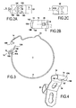
- the collar of the figure 3 is analogous to that of the figure 1 , except that the belt is formed in a single strip portion 17, wound on itself from its first end 10A in the vicinity of which is formed the ear 18, to its second end 10B which is formed the hook 14.
- This portion of single band also has a reserve of elasticity 23 located at the rear of the hook 14. It is seen that the first end 10A extends beyond the ear 18 to form a flap which, at the tight state, extends under the hook 14 and thus ensures a continuity of support on the object clamped by the collar.
- the invention can of course be applied to collars devoid of such a flap.
- the hook 14 On its side, the hook 14 has a front wall 15 which extends radially closer to the center C of the collar from the head 15 'of the hook, which forms the front end of the upper wall 14' of the hook 14
- the upper wall of the hook is in turn oriented substantially in the peripheral direction of the belt. To hook the hook on the ear, this hook is moved relative to the ear 18 in a direction F indicated on the figure 1 until the front wall 15 of the hook is housed behind the ear 18.
- the Figure 2A shows, in top view, the conformation of the ear 18. It is seen that it has a substantially V-shaped whose tip 18A is turned in the direction S away from the hook 14. This meaning is the same that the direction of movement of the hook relative to the ear for attachment.
- the tip 18A of the V is substantially centered on the longitudinal axis L of the metal band of the belt, and on either side of this tip 18A, the ear has symmetrical 18B and 18C branches respectively.
- the tip of the V is dulled by being rounded or shaped flat, and overall occupies a width LP which corresponds to approximately 1/4 to 1/3 of the total width LB of the strip.
- the centering projection is formed by the blunt tip of V.
- the V-shape can also be defined as a U-shape with diverging and symmetrical branches, the base of the U forming the flat 18A.
- the edge of the front wall 15 could be shaped as shown in broken lines and designated by the reference numeral 15 ", so that the radial distance from this edge to the center C of the collar is substantially the same as the In the central portion or in the lateral portions, depending on the conformation of the ear, it could even be chosen that the radial distance is slightly smaller in the central portion than in the lateral portions.
- the side portions 15B and 15C of the front wall 15 of the hook are tucked under this hook. As stated on the figure 6 they are retracted by being folded obliquely with respect to the direction L of the longitudinal axis of the belt.
- the arrows F1 and F2 indicate the directions in which these lateral portions, 15B and 15C, respectively, are retracted, and they are located substantially on oblique lines DB and DC, respectively.
- the angle ⁇ between the lines DB and DC is advantageously of the order of 90 ° to 120 °.
- the lateral portions are folded along fold lines, respectively Lb and Lc which are substantially symmetrical with respect to the longitudinal axis L.
- the angle ⁇ between these lines Lb and Lc is advantageously of the order of 110 ° to 160 ° preferably of the order of 120 ° to 130 °.
- the lateral portions 15B and 15C are well adapted to cooperate with the angled sections respectively formed by the branches 18B and 18C of the V formed by this ear in plan view (see FIG. Figure 2A ).
- the figure 7 shows a band portion 12 flat, before the formation of the hook in an end portion of this portion of tape.
- the tip 10B of this band portion has on almost all of its width LB, a continuous curve C1 whose radius of curvature is constant direction.
- the bandwidth L1 on which this curve C1 extends is of the order of 85 to 95% of the total width LB of the band.
- Only the completely marginal regions adjacent to the margins 10B 'and 10B "of the strip portion have different curvatures, These marginal regions form the corners between the margins of the strip and its free end.
- CI curve with margins 10B 'and 10B "form blunt corners, to avoid that, locally, the efforts of hardening are too important.
- the radius of curvature R of the curve C1 is constant. It is at least equal to 1.5 times the width LB of the strip, and can be much higher since, as indicated by broken lines, the edge can even be rectilinear. It can also be slightly convex, as indicated by the curve C2, in which case it will also have a large radius of curvature of the order of at least 1.5 the width LB of the strip.
- the hook 14 and the lug 18 are respectively formed at the ends of the two band portions 12 and 16.
- the hook and the ear are formed while these band portions are flat, then these strips are rolled and fixed to each other.
- the hook 14 of the lug 18 is formed in the vicinity of the respective ends of the same band portion 17, while the latter is flat, and then this band is rolled to form the collar.
- the hook 14 and the lug 18 are indicated at the ends of the metal belt, which does not mean that they are formed only after this belt itself is shaped belt, by rolling the band or portions of which it is constituted. On the contrary, as indicated, the hook and the ear can be formed flat.
- a centering protrusion is produced on the rear part of this ear, either by conforming the rear fold of the ear with a V configuration in plan view ( Figure 2A ) by forming the rear fold of the double fold with a boss 18'A ( Figure 2C ).
- the centering projection 18A or 18'A may extend substantially over the entire radial height hr (see figure 1 ) of the ear 18 or on the contrary extend only over a portion of this radial height (see reference 18'A on the figure 3 ).
- the hook 14 is formed flat from the portion of the band shown on the figure 7 .
- the end of the strip 14A is deformed which, after forming the hook, will form the front wall 15 of this hook, so that a central portion of the wall in advance advances towards the front from the head 15 'of the hook, towards the free edge 15 ".
- this deformation is advantageously obtained by stamping.
- this stamping is illustrated.
- the band portion 12 is disposed on a stamping die 30, with the band end 14A serving to form the front wall that extends overhang.
- the stamping punch 32 is moved in the direction D indicated on the figure 8 to strike the strip against the matrix, so as to conform the front wall 15.
- the lateral portions 15B and 15C are folded with respect to the central portion in advance, along fold lines 1b and 1c (see FIG. figure 6 ).
Landscapes
- Engineering & Computer Science (AREA)
- General Engineering & Computer Science (AREA)
- Mechanical Engineering (AREA)
- Buckles (AREA)
- Clamps And Clips (AREA)
Claims (14)
- Klemmschelle, umfassend einen Metallring (10; 17), der in der Nähe eines ersten Endes (10A) eine vorspringende Öse (18; 18') und in der Nähe eines zweiten Endes (10B) einen Haken (14) hat, welcher eine vordere Wand (15) aufweist, die dazu bestimmt ist, hinter der Öse gehalten zu werden, während der Haken (14) an der Öse (18; 18') festgehakt ist, um die Schelle im festgezogenen Zustand zu halten, wobei ein hinterer Teil (19) der Öse (18, 18'), welcher von dem Haken (14) abgewandt ist, einen Zentriervorsprung (18A, 18'A) aufweist,
dadurch gekennzeichnet, daß die vordere Wand (15) des Hakens (14) einen mittleren Abschnitt (15A), der von dem Kopf (15') des Hakens nach vorne in Richtung des vorspringenden Randes (15") des mittleren Abschnitts vorspringt, sowie zwei gegenüber dem mittleren Abschnitt zurückspringende Seitenabschnitte (15B, 15C) aufweist. - Schelle nach Anspruch 1, dadurch gekennzeichnet, daß im festgezogenen Zustand der Schelle der radiale Abstand (RC) zwischen dem Mittelpunkt (C) der Schelle und dem Rand (15") der vorderen Wand (15) in dem mittleren Abschnitt (15A) größer als der radiale Abstand (RL) zwischen dem Mittelpunkt (C) der Schelle und dem Rand der vorderen Wand (15) in den Seitenabschnitten (15B, 15C) ist.
- Schelle nach Anspruch 1, dadurch gekennzeichnet, daß im festgezogenen Zustand der Schelle der radiale Abstand (RC) zwischen dem Mittelpunkt (C) der Schelle und dem Rand der vorderen Wand in dem mittleren Abschnitt höchstens im wesentlichen gleich dem radialen Abstand zwischen dem Mittelpunkt der Schelle und dem Rand der vorderen Wand in den Seitenabschnitten ist.
- Schelle nach einem der Ansprüche 1 bis 3, dadurch gekennzeichnet, daß die Seitenabschnitte (15B, 15C) der vorderen Wand (15) des Hakens (14) unter den Haken (14) eingeschlagen sind, indem sie gegenüber der Längsrichtung (L) des Rings sowie aufeinander zu schräg umgebogen sind, und daß die hintere Wand (19) der Öse (18; 18') zwei schräge Abschnitte (18B, 18C) aufweist, die geeignet sind, jeweils mit einem der umgebogenen Seitenabschnitte (15B, 15C) zusammenzuwirken.
- Schelle nach Anspruch 4, dadurch gekennzeichnet, daß die Seitenabschnitte (15B, 15C) entlang von jeweiligen Falzlinien (Lb, Lc), die in Bezug auf die Längsrichtung des Rings symmetrisch sind, umgebogen sind.
- Schelle nach Anspruch 4 oder 5, dadurch gekennzeichnet, daß die Öse (18) durch einen Doppelfalz gebildet ist, welcher in Draufsicht im wesentlichen eine V-Form aufweist, deren Spitze (18A) in die sich von dem Haken (14) entfernende Richtung gewandt ist.
- Verfahren zur Herstellung einer Klemmschelle, wobei ein Metallring (10) aus wenigstens einem Metallband (12, 16), das auf sich selbst gerollt wird, ausgebildet wird, in der Nähe eines ersten Endes (10A) des Rings eine vorspringende Öse (18, 18') gebildet wird und ein Zentriervorsprung (18A, 18'A) an einem hinteren Basisteil dieser Öse ausgebildet wird und in der Nähe eines zweiten Endes (10B) ein Haken (14) gebildet wird, welcher dazu bestimmt ist, an der Öse festgehakt zu werden, um durch Festhalten der vorderen Wand (15) des Hakens (14) hinter der Öse (18, 18') die Schelle in dem festgezogenen Zustand zu halten,
dadurch gekennzeichnet, daß zur Bildung der vorderen Wand (15) des Hakens (14) das Bandende (14A), welches nach Bildung des Hakens (14) die vordere Wand (15) dieses Hakens bildet, derart verformt wird, daß ein mittlerer Abschnitt (15A) der vorderen Wand (15) von dem Kopf (15') des Hakens (14) nach vorne in Richtung des vorspringenden freien Randes (15") des mittleren Abschnitts (15A) vorspringt, und gleichzeitig die Seitenabschnitte (15B, 15C) der vorderen Wand unter den Haken (14) eingeschlagen werden, wodurch sie gegenüber dem mittleren Abschnitt zurückspringend angeordnet werden. - Verfahren nach Anspruch 7, dadurch gekennzeichnet, daß das Bandende (14A) durch Tiefziehen verformt wird.
- Verfahren nach Anspruch 7 oder 8, dadurch gekennzeichnet, daß vor dem Verformen des Bandendes (14A) der Rand des Bandendes entlang einer stetigen Kurve, deren Krümmungsradius (C1, C2) eine konstante Richtung aufweist, geschnitten wird.
- Verfahren nach Anspruch 9, dadurch gekennzeichnet, daß der mittlere Krümmungsradius (R) der Kurve wenigstens gleich dem 1,5-fachen der Breite des Bandes ist.
- Verfahren nach einem der Ansprüche 7 bis 10, dadurch gekennzeichnet, daß das Bandende (14A) derart verformt wird, daß im festgezogenen Zustand der Schelle der radiale Abstand (RC) zwischen dem Mittelpunkt der Schelle und dem Rand (15") der vorderen Wand (15) in dem mittleren Abschnitt (15A) größer als der radiale Abstand (RL) zwischen dem Mittelpunkt der Schelle und dem Rand der vorderen Wand in den Seitenabschnitten (15B, 15C) ist.
- Verfahren nach einem der Ansprüche 7 bis 10, dadurch gekennzeichnet, daß das Bandende (14A) derart verformt wird, daß im festgezogenen Zustand der Schelle der radiale Abstand zwischen dem Mittelpunkt der Schelle und dem Rand der vorderen Wand in dem mittleren Abschnitt höchstens im wesentlichen gleich dem radialen Abstand zwischen dem Mittelpunkt der Schelle und dem Rand der vorderen Wand in den Seitenabschnitten ist.
- Verfahren nach einem der Ansprüche 7 bis 12, dadurch gekennzeichnet, daß die Seitenabschnitte (15B, 15C) der vorderen Wand (15) unter den Haken (14) eingeschlagen werden, indem diese Seitenabschnitte gegenüber der Längsrichtung (L) des Bandes sowie aufeinander zu schräg umgebogen werden.
- Verfahren nach Anspruch 13, dadurch gekennzeichnet, daß die Seitenabschnitte entlang von zwei jeweiligen Falzlinien (Lb, Lc), die in Bezug auf die Längsachse des Bandes symmetrisch sind, umgebogen werden.
Applications Claiming Priority (2)
| Application Number | Priority Date | Filing Date | Title |
|---|---|---|---|
| FR0956603A FR2950403B1 (fr) | 2009-09-24 | 2009-09-24 | Collier de serrage et son procede de fabrication. |
| PCT/FR2010/051800 WO2011036365A2 (fr) | 2009-09-24 | 2010-08-30 | Collier de serrage et son procede de fabrication. |
Publications (2)
| Publication Number | Publication Date |
|---|---|
| EP2480355A2 EP2480355A2 (de) | 2012-08-01 |
| EP2480355B1 true EP2480355B1 (de) | 2013-06-19 |
Family
ID=42173358
Family Applications (1)
| Application Number | Title | Priority Date | Filing Date |
|---|---|---|---|
| EP10763774.6A Active EP2480355B1 (de) | 2009-09-24 | 2010-08-30 | Klemmring und dessen herstellungsverfahren |
Country Status (3)
| Country | Link |
|---|---|
| EP (1) | EP2480355B1 (de) |
| FR (1) | FR2950403B1 (de) |
| WO (1) | WO2011036365A2 (de) |
Cited By (1)
| Publication number | Priority date | Publication date | Assignee | Title |
|---|---|---|---|---|
| US11674625B2 (en) | 2019-09-23 | 2023-06-13 | Caillau | Clamping collar |
Families Citing this family (2)
| Publication number | Priority date | Publication date | Assignee | Title |
|---|---|---|---|---|
| FR3101118B1 (fr) | 2019-09-23 | 2021-10-01 | Caillau | Collier de serrage |
| FR3119650B1 (fr) | 2021-02-09 | 2023-04-14 | Caillau | Collier de serrage ayant un organe de retenue et un crochet |
Family Cites Families (6)
| Publication number | Priority date | Publication date | Assignee | Title |
|---|---|---|---|---|
| GB430142A (en) * | 1933-12-01 | 1935-06-13 | Helge Alfred Borresen | Improvements in and relating to hose clamps |
| FR2632049B1 (fr) * | 1988-05-25 | 1990-10-05 | Caillau Ets | Collier de serrage |
| DK198190D0 (da) * | 1990-08-20 | 1990-08-20 | S B Multi Spaend Aps | Spaendemekanisme til at spaende et spaendebaand |
| FR2705411B1 (fr) | 1993-05-19 | 1995-08-18 | Caillau Ets | Structure de collier de serrage. |
| FR2726208B1 (fr) | 1994-11-02 | 1997-01-17 | Caillau Ets | Procede de retreint |
| FR2818352B1 (fr) * | 2000-12-19 | 2003-04-18 | Caillau Ets | Collier de serrage |
-
2009
- 2009-09-24 FR FR0956603A patent/FR2950403B1/fr not_active Expired - Fee Related
-
2010
- 2010-08-30 WO PCT/FR2010/051800 patent/WO2011036365A2/fr active Application Filing
- 2010-08-30 EP EP10763774.6A patent/EP2480355B1/de active Active
Cited By (1)
| Publication number | Priority date | Publication date | Assignee | Title |
|---|---|---|---|---|
| US11674625B2 (en) | 2019-09-23 | 2023-06-13 | Caillau | Clamping collar |
Also Published As
| Publication number | Publication date |
|---|---|
| EP2480355A2 (de) | 2012-08-01 |
| FR2950403A1 (fr) | 2011-03-25 |
| WO2011036365A2 (fr) | 2011-03-31 |
| FR2950403B1 (fr) | 2011-10-21 |
| WO2011036365A3 (fr) | 2011-09-09 |
Similar Documents
| Publication | Publication Date | Title |
|---|---|---|
| EP2017518B1 (de) | Klemmvorrichtung mit Schlauchklemme und Positionierteil | |
| EP2136120B1 (de) | Rohrschelle mit verformtem Rasthaken | |
| EP3189261B1 (de) | Kopplungssystem für zwei rohre | |
| EP3157837B1 (de) | Bandklemme mit durchgangsreifen und spannwerkzeug | |
| EP2310734B1 (de) | Spannvorrichtung mit klemmschelle | |
| FR2950402A1 (fr) | Collier de serrage. | |
| EP2480355B1 (de) | Klemmring und dessen herstellungsverfahren | |
| EP3157836A1 (de) | Bandklemme mit durchgangsreifen | |
| EP0949977B1 (de) | Verfahren zum quereinpressen eines zylindrischen teils in ein rohrförmiges teil und entsprechende einheit aus zwei teilen | |
| WO2008006989A2 (fr) | Collier de serrage | |
| EP1540229B1 (de) | Klemmring | |
| EP3561360A1 (de) | Spannsystem mit herunterklappbaren spannbacken für den anschluss von rohren | |
| EP1352192B1 (de) | Klemmring | |
| EP3795878A1 (de) | Klemmring | |
| FR2974879A1 (fr) | Collier de serrage a charniere | |
| FR2794819A1 (fr) | Collier de serrage | |
| FR2790214A1 (fr) | Bague a retreindre et son procede de fabrication | |
| EP3670989B1 (de) | Spannvorrichtung, die einen riemen und zwei versetzte spannklemmen umfasst | |
| EP3795877B1 (de) | Schlauchklemme | |
| EP0707996A1 (de) | Verfahren zur Befestigung einer Luftzuführhause an einem Kühlradiator | |
| FR2954204A1 (fr) | Pince coupante pour collier de serrage | |
| EP1083376A1 (de) | Scheckengewindeschelle | |
| FR2818351A1 (fr) | Collier de serrage | |
| BE374537A (de) | ||
| FR2957228A1 (fr) | Eperon |
Legal Events
| Date | Code | Title | Description |
|---|---|---|---|
| PUAI | Public reference made under article 153(3) epc to a published international application that has entered the european phase |
Free format text: ORIGINAL CODE: 0009012 |
|
| 17P | Request for examination filed |
Effective date: 20120322 |
|
| AK | Designated contracting states |
Kind code of ref document: A2 Designated state(s): AL AT BE BG CH CY CZ DE DK EE ES FI FR GB GR HR HU IE IS IT LI LT LU LV MC MK MT NL NO PL PT RO SE SI SK SM TR |
|
| RIN1 | Information on inventor provided before grant (corrected) |
Inventor name: BEAUVAIS, JULIEN Inventor name: FOUQUERAY, CYRIAQUE Inventor name: LACHE, CHRISTOPHE |
|
| DAX | Request for extension of the european patent (deleted) | ||
| REG | Reference to a national code |
Ref country code: DE Ref legal event code: R079 Ref document number: 602010007978 Country of ref document: DE Free format text: PREVIOUS MAIN CLASS: B21D0053360000 Ipc: F16L0033025000 |
|
| GRAP | Despatch of communication of intention to grant a patent |
Free format text: ORIGINAL CODE: EPIDOSNIGR1 |
|
| RIC1 | Information provided on ipc code assigned before grant |
Ipc: F16B 2/08 20060101ALI20130111BHEP Ipc: F16B 2/20 20060101ALI20130111BHEP Ipc: B21D 53/36 20060101ALI20130111BHEP Ipc: F16L 33/035 20060101ALI20130111BHEP Ipc: F16L 33/025 20060101AFI20130111BHEP |
|
| GRAS | Grant fee paid |
Free format text: ORIGINAL CODE: EPIDOSNIGR3 |
|
| GRAA | (expected) grant |
Free format text: ORIGINAL CODE: 0009210 |
|
| AK | Designated contracting states |
Kind code of ref document: B1 Designated state(s): AL AT BE BG CH CY CZ DE DK EE ES FI FR GB GR HR HU IE IS IT LI LT LU LV MC MK MT NL NO PL PT RO SE SI SK SM TR |
|
| REG | Reference to a national code |
Ref country code: GB Ref legal event code: FG4D Free format text: NOT ENGLISH |
|
| REG | Reference to a national code |
Ref country code: CH Ref legal event code: EP |
|
| REG | Reference to a national code |
Ref country code: AT Ref legal event code: REF Ref document number: 617862 Country of ref document: AT Kind code of ref document: T Effective date: 20130715 |
|
| REG | Reference to a national code |
Ref country code: IE Ref legal event code: FG4D Free format text: LANGUAGE OF EP DOCUMENT: FRENCH |
|
| REG | Reference to a national code |
Ref country code: DE Ref legal event code: R096 Ref document number: 602010007978 Country of ref document: DE Effective date: 20130814 |
|
| PG25 | Lapsed in a contracting state [announced via postgrant information from national office to epo] |
Ref country code: SE Free format text: LAPSE BECAUSE OF FAILURE TO SUBMIT A TRANSLATION OF THE DESCRIPTION OR TO PAY THE FEE WITHIN THE PRESCRIBED TIME-LIMIT Effective date: 20130619 Ref country code: FI Free format text: LAPSE BECAUSE OF FAILURE TO SUBMIT A TRANSLATION OF THE DESCRIPTION OR TO PAY THE FEE WITHIN THE PRESCRIBED TIME-LIMIT Effective date: 20130619 Ref country code: NO Free format text: LAPSE BECAUSE OF FAILURE TO SUBMIT A TRANSLATION OF THE DESCRIPTION OR TO PAY THE FEE WITHIN THE PRESCRIBED TIME-LIMIT Effective date: 20130919 Ref country code: LT Free format text: LAPSE BECAUSE OF FAILURE TO SUBMIT A TRANSLATION OF THE DESCRIPTION OR TO PAY THE FEE WITHIN THE PRESCRIBED TIME-LIMIT Effective date: 20130619 Ref country code: GR Free format text: LAPSE BECAUSE OF FAILURE TO SUBMIT A TRANSLATION OF THE DESCRIPTION OR TO PAY THE FEE WITHIN THE PRESCRIBED TIME-LIMIT Effective date: 20130920 Ref country code: SI Free format text: LAPSE BECAUSE OF FAILURE TO SUBMIT A TRANSLATION OF THE DESCRIPTION OR TO PAY THE FEE WITHIN THE PRESCRIBED TIME-LIMIT Effective date: 20130619 Ref country code: ES Free format text: LAPSE BECAUSE OF FAILURE TO SUBMIT A TRANSLATION OF THE DESCRIPTION OR TO PAY THE FEE WITHIN THE PRESCRIBED TIME-LIMIT Effective date: 20130930 |
|
| REG | Reference to a national code |
Ref country code: AT Ref legal event code: MK05 Ref document number: 617862 Country of ref document: AT Kind code of ref document: T Effective date: 20130619 |
|
| REG | Reference to a national code |
Ref country code: LT Ref legal event code: MG4D |
|
| PG25 | Lapsed in a contracting state [announced via postgrant information from national office to epo] |
Ref country code: BG Free format text: LAPSE BECAUSE OF FAILURE TO SUBMIT A TRANSLATION OF THE DESCRIPTION OR TO PAY THE FEE WITHIN THE PRESCRIBED TIME-LIMIT Effective date: 20130919 Ref country code: HR Free format text: LAPSE BECAUSE OF FAILURE TO SUBMIT A TRANSLATION OF THE DESCRIPTION OR TO PAY THE FEE WITHIN THE PRESCRIBED TIME-LIMIT Effective date: 20130619 |
|
| REG | Reference to a national code |
Ref country code: NL Ref legal event code: VDEP Effective date: 20130619 |
|
| PG25 | Lapsed in a contracting state [announced via postgrant information from national office to epo] |
Ref country code: LV Free format text: LAPSE BECAUSE OF FAILURE TO SUBMIT A TRANSLATION OF THE DESCRIPTION OR TO PAY THE FEE WITHIN THE PRESCRIBED TIME-LIMIT Effective date: 20130619 |
|
| PG25 | Lapsed in a contracting state [announced via postgrant information from national office to epo] |
Ref country code: CY Free format text: LAPSE BECAUSE OF FAILURE TO SUBMIT A TRANSLATION OF THE DESCRIPTION OR TO PAY THE FEE WITHIN THE PRESCRIBED TIME-LIMIT Effective date: 20130904 Ref country code: EE Free format text: LAPSE BECAUSE OF FAILURE TO SUBMIT A TRANSLATION OF THE DESCRIPTION OR TO PAY THE FEE WITHIN THE PRESCRIBED TIME-LIMIT Effective date: 20130619 Ref country code: CZ Free format text: LAPSE BECAUSE OF FAILURE TO SUBMIT A TRANSLATION OF THE DESCRIPTION OR TO PAY THE FEE WITHIN THE PRESCRIBED TIME-LIMIT Effective date: 20130619 Ref country code: PT Free format text: LAPSE BECAUSE OF FAILURE TO SUBMIT A TRANSLATION OF THE DESCRIPTION OR TO PAY THE FEE WITHIN THE PRESCRIBED TIME-LIMIT Effective date: 20131021 Ref country code: AT Free format text: LAPSE BECAUSE OF FAILURE TO SUBMIT A TRANSLATION OF THE DESCRIPTION OR TO PAY THE FEE WITHIN THE PRESCRIBED TIME-LIMIT Effective date: 20130619 Ref country code: IS Free format text: LAPSE BECAUSE OF FAILURE TO SUBMIT A TRANSLATION OF THE DESCRIPTION OR TO PAY THE FEE WITHIN THE PRESCRIBED TIME-LIMIT Effective date: 20131019 Ref country code: SK Free format text: LAPSE BECAUSE OF FAILURE TO SUBMIT A TRANSLATION OF THE DESCRIPTION OR TO PAY THE FEE WITHIN THE PRESCRIBED TIME-LIMIT Effective date: 20130619 |
|
| BERE | Be: lapsed |
Owner name: ETS CAILLAU Effective date: 20130831 |
|
| PG25 | Lapsed in a contracting state [announced via postgrant information from national office to epo] |
Ref country code: RO Free format text: LAPSE BECAUSE OF FAILURE TO SUBMIT A TRANSLATION OF THE DESCRIPTION OR TO PAY THE FEE WITHIN THE PRESCRIBED TIME-LIMIT Effective date: 20130619 Ref country code: PL Free format text: LAPSE BECAUSE OF FAILURE TO SUBMIT A TRANSLATION OF THE DESCRIPTION OR TO PAY THE FEE WITHIN THE PRESCRIBED TIME-LIMIT Effective date: 20130619 Ref country code: NL Free format text: LAPSE BECAUSE OF FAILURE TO SUBMIT A TRANSLATION OF THE DESCRIPTION OR TO PAY THE FEE WITHIN THE PRESCRIBED TIME-LIMIT Effective date: 20130619 |
|
| PG25 | Lapsed in a contracting state [announced via postgrant information from national office to epo] |
Ref country code: CY Free format text: LAPSE BECAUSE OF FAILURE TO SUBMIT A TRANSLATION OF THE DESCRIPTION OR TO PAY THE FEE WITHIN THE PRESCRIBED TIME-LIMIT Effective date: 20130619 |
|
| PLBE | No opposition filed within time limit |
Free format text: ORIGINAL CODE: 0009261 |
|
| STAA | Information on the status of an ep patent application or granted ep patent |
Free format text: STATUS: NO OPPOSITION FILED WITHIN TIME LIMIT |
|
| PG25 | Lapsed in a contracting state [announced via postgrant information from national office to epo] |
Ref country code: MC Free format text: LAPSE BECAUSE OF FAILURE TO SUBMIT A TRANSLATION OF THE DESCRIPTION OR TO PAY THE FEE WITHIN THE PRESCRIBED TIME-LIMIT Effective date: 20130619 Ref country code: DK Free format text: LAPSE BECAUSE OF FAILURE TO SUBMIT A TRANSLATION OF THE DESCRIPTION OR TO PAY THE FEE WITHIN THE PRESCRIBED TIME-LIMIT Effective date: 20130619 |
|
| REG | Reference to a national code |
Ref country code: IE Ref legal event code: MM4A |
|
| 26N | No opposition filed |
Effective date: 20140320 |
|
| PG25 | Lapsed in a contracting state [announced via postgrant information from national office to epo] |
Ref country code: BE Free format text: LAPSE BECAUSE OF NON-PAYMENT OF DUE FEES Effective date: 20130831 |
|
| REG | Reference to a national code |
Ref country code: DE Ref legal event code: R097 Ref document number: 602010007978 Country of ref document: DE Effective date: 20140320 |
|
| PG25 | Lapsed in a contracting state [announced via postgrant information from national office to epo] |
Ref country code: IE Free format text: LAPSE BECAUSE OF NON-PAYMENT OF DUE FEES Effective date: 20130830 |
|
| REG | Reference to a national code |
Ref country code: CH Ref legal event code: PL |
|
| GBPC | Gb: european patent ceased through non-payment of renewal fee |
Effective date: 20140830 |
|
| PG25 | Lapsed in a contracting state [announced via postgrant information from national office to epo] |
Ref country code: CH Free format text: LAPSE BECAUSE OF NON-PAYMENT OF DUE FEES Effective date: 20140831 Ref country code: LI Free format text: LAPSE BECAUSE OF NON-PAYMENT OF DUE FEES Effective date: 20140831 |
|
| PG25 | Lapsed in a contracting state [announced via postgrant information from national office to epo] |
Ref country code: SM Free format text: LAPSE BECAUSE OF FAILURE TO SUBMIT A TRANSLATION OF THE DESCRIPTION OR TO PAY THE FEE WITHIN THE PRESCRIBED TIME-LIMIT Effective date: 20130619 |
|
| PG25 | Lapsed in a contracting state [announced via postgrant information from national office to epo] |
Ref country code: TR Free format text: LAPSE BECAUSE OF FAILURE TO SUBMIT A TRANSLATION OF THE DESCRIPTION OR TO PAY THE FEE WITHIN THE PRESCRIBED TIME-LIMIT Effective date: 20130619 Ref country code: MT Free format text: LAPSE BECAUSE OF FAILURE TO SUBMIT A TRANSLATION OF THE DESCRIPTION OR TO PAY THE FEE WITHIN THE PRESCRIBED TIME-LIMIT Effective date: 20130619 |
|
| PG25 | Lapsed in a contracting state [announced via postgrant information from national office to epo] |
Ref country code: HU Free format text: LAPSE BECAUSE OF FAILURE TO SUBMIT A TRANSLATION OF THE DESCRIPTION OR TO PAY THE FEE WITHIN THE PRESCRIBED TIME-LIMIT; INVALID AB INITIO Effective date: 20100830 Ref country code: GB Free format text: LAPSE BECAUSE OF NON-PAYMENT OF DUE FEES Effective date: 20140830 Ref country code: LU Free format text: LAPSE BECAUSE OF NON-PAYMENT OF DUE FEES Effective date: 20130830 Ref country code: MK Free format text: LAPSE BECAUSE OF FAILURE TO SUBMIT A TRANSLATION OF THE DESCRIPTION OR TO PAY THE FEE WITHIN THE PRESCRIBED TIME-LIMIT Effective date: 20130619 |
|
| REG | Reference to a national code |
Ref country code: FR Ref legal event code: PLFP Year of fee payment: 7 |
|
| REG | Reference to a national code |
Ref country code: FR Ref legal event code: PLFP Year of fee payment: 8 |
|
| REG | Reference to a national code |
Ref country code: FR Ref legal event code: PLFP Year of fee payment: 9 |
|
| PG25 | Lapsed in a contracting state [announced via postgrant information from national office to epo] |
Ref country code: AL Free format text: LAPSE BECAUSE OF FAILURE TO SUBMIT A TRANSLATION OF THE DESCRIPTION OR TO PAY THE FEE WITHIN THE PRESCRIBED TIME-LIMIT Effective date: 20130619 |
|
| PGFP | Annual fee paid to national office [announced via postgrant information from national office to epo] |
Ref country code: IT Payment date: 20230809 Year of fee payment: 14 |
|
| PGFP | Annual fee paid to national office [announced via postgrant information from national office to epo] |
Ref country code: FR Payment date: 20230816 Year of fee payment: 14 Ref country code: DE Payment date: 20230808 Year of fee payment: 14 |