EP1083376A1 - Scheckengewindeschelle - Google Patents
Scheckengewindeschelle Download PDFInfo
- Publication number
- EP1083376A1 EP1083376A1 EP00402477A EP00402477A EP1083376A1 EP 1083376 A1 EP1083376 A1 EP 1083376A1 EP 00402477 A EP00402477 A EP 00402477A EP 00402477 A EP00402477 A EP 00402477A EP 1083376 A1 EP1083376 A1 EP 1083376A1
- Authority
- EP
- European Patent Office
- Prior art keywords
- strip
- housing
- sole
- window
- longitudinal
- Prior art date
- Legal status (The legal status is an assumption and is not a legal conclusion. Google has not performed a legal analysis and makes no representation as to the accuracy of the status listed.)
- Withdrawn
Links
Images


Classifications
-
- F—MECHANICAL ENGINEERING; LIGHTING; HEATING; WEAPONS; BLASTING
- F16—ENGINEERING ELEMENTS AND UNITS; GENERAL MEASURES FOR PRODUCING AND MAINTAINING EFFECTIVE FUNCTIONING OF MACHINES OR INSTALLATIONS; THERMAL INSULATION IN GENERAL
- F16L—PIPES; JOINTS OR FITTINGS FOR PIPES; SUPPORTS FOR PIPES, CABLES OR PROTECTIVE TUBING; MEANS FOR THERMAL INSULATION IN GENERAL
- F16L33/00—Arrangements for connecting hoses to rigid members; Rigid hose connectors, i.e. single members engaging both hoses
- F16L33/02—Hose-clips
- F16L33/08—Hose-clips in which a worm coacts with a part of the hose-encircling member that is toothed like a worm-wheel
Definitions
- the present invention relates to a clamp type of "screw tangent ", comprising a metal band wound on itself, a screw clamp and a housing attached to a first end of the strip.
- the housing has a cover disposed on the outside of the strip and a sole which extends against the inner face of the strip and which is fixed to the latter by fixing means, said fixing means comprising at least one window made in a first end of the band and at least one tab or extension which is integral with the sole of the housing and which enters this window, the screw having a threaded barrel which is engaged in the cover, the second end of the strip being susceptible to be inserted in the cover, between the threaded barrel of the screw and the first end of the strip, the threaded barrel of the screw being capable of cooperating with said second end to tighten the collar.
- these fixing means comprise windows made in the band, these correspond to a zone of fragility of this bandaged. This results in a risk of deterioration of the collar in this area. when, in particular during tightening, the tensile forces are high.
- the present invention applies to a tangent screw collar and has for purpose of improving the means of fixing the housing to the band of this collar to better distribute the reaction forces due to the traction forces caused by the tightening of the collar and to ensure that these efforts relate to an area of the strip that is less fragile.
- the invention applies in particular to screw clamps tangent in which the means for fixing the housing relative to the strip include at least one window made in the first end of the strip and at least one tab or extension which is integral with the sole of the case and which enters this window.
- the fixing means comprise at least one longitudinal wedging assembly comprising an openwork in a middle region of the sole of the housing and a boss, formed in projection on the inside of the strip and penetrating into said aperture.
- the boss formed in the strip does not appreciably reduce the mechanical resistance of the latter. If it is of reduced size, it has even rather tend to locally increase this resistance.
- the openwork is practiced in a central region of the sole and can have dimensions such that they have little effect on mechanical strength of the latter.
- the band of the necklace is made from a thin strip.
- the metal that is the case has a slightly greater thickness and it is more resistant. Therefore, the fact that the opening of the set of longitudinal wedging is practiced in the sole of the case does not affect the mechanical resistance of this case in proportions such that it could result in a risk of deterioration of the collar under the effect of the efforts of tension normally applied to this collar when tightening or slightly higher than these "normal" efforts.
- the reaction efforts to the traction on the strip is exerted mainly on the set or sets of longitudinal setting, with possible distribution on the other elements fixing means.
- the boss of the or each wedging assembly longitudinal has a sharp edge facing away from the free end of the first end of the strip and cooperating with the edge of the opening correspondent located opposite.
- the sharp edge of the boss cooperates in abutment with the edge of the aperture without any risk of relative slippage, even under the effect high tensile forces.
- This boss is advantageously formed by a puncture, that is to say by a pin pushed back on the inside of the strip until it shears partial to this strip, the sheared edge forming the sharp edge mentioned above.
- the collar comprises two longitudinal setting assemblies arranged on either side of an axis longitudinal median of the strip.
- the tensile forces are distributed appreciably homogeneous on each of the two sets of longitudinal setting.
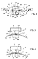
- the collar of Figure 1 has a metal strip 10 wound on itself, of which only the end portions 10A and 10B are shown.
- the collar includes a clamping screw 12 disposed in a housing 14, which comprises a cover 16 extending from the outside of the collar and a sole 18, fixed to the first end 10A and the strip and arranged against the face inner 11A of the latter.
- the screw 12 has a screwing head 12A arranged outside the cover 16 and a threaded barrel 12B, indicated in line interrupted, which extends inside this cover.
- the first end 10B of the strip is inserted into the cover, between the outer face 11B of the strip and the threaded barrel of the screw.
- At least the second end 10B of the strip is provided with rack surfaces (slots or reliefs), with which the threads of the screw are able to cooperate during the screwing of this last in direction R to tighten the collar.
- the means of fixing the housing by compared to the strip include two windows, 20 and 22, which are practiced in the strip and which are spaced longitudinally from each other, thus only legs which form longitudinal extensions of the sole of the case and which are engaged in these windows, so as to appear on the outer face 11B of the strip.
- Longitudinal window spacing 20 and 22 is substantially equal to the length of the housing in the area of the latter which is devoid of extensions.
- the fixing means comprise two sets of fixation respectively arranged on either side of a region T of the sole transverse to the band.
- Two openings, respectively 26 and 28, are practiced in a region median of the sole 18 of the case.
- two bosses, respectively 30 and 32 are formed projecting from the inner face of the strip, at the first end 10A of the latter, and thus each penetrate into the corresponding aperture. So, in Figure 3, we sees the aperture 26 into which the boss 30 enters, while FIG. 4 shows the aperture 28 into which the boss 32 enters.
- the fixing means from the housing to the band include two sets of longitudinal wedging each comprising an aperture and a boss associated therewith, these two assemblies being arranged on either side of the median longitudinal axis of the band M.
- Each of the bosses has a sharp edge, respectively 30A and 32A, which cooperates with an edge of the corresponding aperture.
- the sharp edge is facing away from the free end 10'A of the first end 10A of the strip in which the boss is carried which carries this free edge.
- the first end 10A of this the latter is stressed in tension with respect to the housing in the direction of the arrow F.
- the reaction effects of the case are therefore exerted on the free edge of the boss and the edge of the aperture with which it cooperates. So the necklace is reinforced without using solder points between the housing and the bandaged.
- the bosses 30 and 32 are both formed by punctures, which are achieved by a simple operation of pushing and shearing and which have the advantage of presenting the edges free previously mentioned.
- Openwork 26 and 28 are performed in mid-regions of the sole 18 of the housing, that is to say substantially equidistant from the edges front 18 'and rear 18 "of this sole.
- the bosses 30 and 32 are them spanned in a region of the first end 10A of the strip which is between windows 20 and 22 through which the legs of the fixing the housing and substantially equal distance from these windows.
- openings 26 and 28 and the bosses 30 and 32 are provided in regions of the sole of the housing and of the first end of the strip not otherwise affected by cuts or the like likely to locally reduce their mechanical strength.
- the cover 16 of the housing has an axial wall (in the direction of the length of the strip) which has the shape of a portion of cylinder to receive the screw 12. From this portion of cylinder extend wings 17A and 17B, each of them having a part which forms a side wall of the housing and an end portion, respectively 18A and 18B, which is folded against the inner face 11A of the strip.
- Part 18A of wing 17A has, substantially in the extension of its longitudinal end edge, a first tab 34A which extends towards the end 10'A of the strip and a second tab 36A which extends in the other direction.
- part 18B of the wing 17B has a first tab 34B and a second tab 36B.
- the two tabs 34A and 34B are juxtaposed in being separated by a cutout 31 which corresponds to the extension of the longitudinal edges of the two wings, as well as the two legs 36A and 36B are juxtaposed by being separated by a cutout 33.
- the two legs 34A and 34B pass through the window 20 to be arranged on the outside of the end 10A of the strip, as shown seen in Figures 3 and 4.
- the window 22 has a width only adapted to allow it to receive the tab 36B.
- This window is substantially interrupted on the median axis of the strip so that the strip remains full in the region in which it cooperates with tab 36A.
- window 22 through which only passes tab 36B.
- a routing 40 which forms a recess on the inner face of the strip.
- a projection 42 is produced in the region of the window 22 and of the plunge 40 .
- the tab 36A which remains on the inner side of the strip is housed in the recess formed under the groove 40 and is wedged laterally by the longitudinal edges of this plunge. This one is indeed not only made by stamping, but also by cutting longitudinal 41 at least on the side opposite window 22, allowing it to remain a sharp blocking edge 41A.
- Figures 6 and 7 show an alternative embodiment for fixing means.
- the bosses 30 and 32 similar to those of the previous figures, these bosses appearing in hollow in FIG. 6.
- the window 20 also has its front edge formed in a depression 38. This time, the projection 42 of FIG. 5 is absent, the face outside of the strip remaining on the same radius.
- the rear window 22 has a rear edge housed in a depression 44 formed in hollow on the outer face of the strip. So the leg 36B can be accommodated in the thickness of this depression so that that its outer face is on the same radius as the outer face of the strip portion 10A.
- a stamping 50 is formed along the edge longitudinal of the strip, on the other side of the median axis M of this strip from window 22. Viewed from the inside of the strip visible in Figure 7, the depressions 38 and 44 and the stamped 50 form bosses.
- the longitudinal edge 50A of the stamped 50 projecting from the face inside of the strip forms a sharp edge for longitudinal locking.
- the openings 26 and 28 are constituted by simple circular holes in the sole of the housing, respectively practiced in parts 18A and 18B of the wings 17A and 17B. These openings are made in a central region of these parts 18A and 18B.
- the punctures 30 and 32 are produced in such a way that their sheared edges 30 and 32A have a contour conforming to the shape of the edge of the openings, for example a partially circular outline.
Applications Claiming Priority (2)
| Application Number | Priority Date | Filing Date | Title |
|---|---|---|---|
| FR9911340 | 1999-09-10 | ||
| FR9911340A FR2798429B1 (fr) | 1999-09-10 | 1999-09-10 | Collier de serrage a vis tangente |
Publications (1)
| Publication Number | Publication Date |
|---|---|
| EP1083376A1 true EP1083376A1 (de) | 2001-03-14 |
Family
ID=9549715
Family Applications (1)
| Application Number | Title | Priority Date | Filing Date |
|---|---|---|---|
| EP00402477A Withdrawn EP1083376A1 (de) | 1999-09-10 | 2000-09-08 | Scheckengewindeschelle |
Country Status (2)
| Country | Link |
|---|---|
| EP (1) | EP1083376A1 (de) |
| FR (1) | FR2798429B1 (de) |
Cited By (2)
| Publication number | Priority date | Publication date | Assignee | Title |
|---|---|---|---|---|
| EP1158235A2 (de) * | 2000-05-25 | 2001-11-28 | Rasmussen GmbH | Schneckengewindeschelle |
| ES2415249A1 (es) * | 2013-03-27 | 2013-07-24 | Grupo Mikalor, S.L. | Abrazadera |
Citations (4)
| Publication number | Priority date | Publication date | Assignee | Title |
|---|---|---|---|---|
| FR928736A (fr) * | 1944-10-25 | 1947-12-05 | Collier de serrage à vis sans fin | |
| FR1276008A (fr) * | 1960-07-29 | 1961-11-17 | Collier de serrage perfectionné | |
| US3351989A (en) * | 1966-12-05 | 1967-11-14 | Sterling Automotive Mfg Co Inc | Hose clamp |
| EP0976960A1 (de) * | 1998-07-29 | 2000-02-02 | Serflex | Schneckengewindeschelle |
Family Cites Families (2)
| Publication number | Priority date | Publication date | Assignee | Title |
|---|---|---|---|---|
| GB660981A (en) | 1944-08-10 | 1951-11-14 | Michael Thomas Usborne Collier | Improvements in or relating to hose clips or clamps |
| US2395275A (en) | 1944-11-22 | 1946-02-19 | Jackson Arch Robert | Collapsible child's cart |
-
1999
- 1999-09-10 FR FR9911340A patent/FR2798429B1/fr not_active Expired - Lifetime
-
2000
- 2000-09-08 EP EP00402477A patent/EP1083376A1/de not_active Withdrawn
Patent Citations (4)
| Publication number | Priority date | Publication date | Assignee | Title |
|---|---|---|---|---|
| FR928736A (fr) * | 1944-10-25 | 1947-12-05 | Collier de serrage à vis sans fin | |
| FR1276008A (fr) * | 1960-07-29 | 1961-11-17 | Collier de serrage perfectionné | |
| US3351989A (en) * | 1966-12-05 | 1967-11-14 | Sterling Automotive Mfg Co Inc | Hose clamp |
| EP0976960A1 (de) * | 1998-07-29 | 2000-02-02 | Serflex | Schneckengewindeschelle |
Cited By (3)
| Publication number | Priority date | Publication date | Assignee | Title |
|---|---|---|---|---|
| EP1158235A2 (de) * | 2000-05-25 | 2001-11-28 | Rasmussen GmbH | Schneckengewindeschelle |
| EP1158235A3 (de) * | 2000-05-25 | 2003-01-02 | Rasmussen GmbH | Schneckengewindeschelle |
| ES2415249A1 (es) * | 2013-03-27 | 2013-07-24 | Grupo Mikalor, S.L. | Abrazadera |
Also Published As
| Publication number | Publication date |
|---|---|
| FR2798429B1 (fr) | 2001-11-30 |
| FR2798429A1 (fr) | 2001-03-16 |
Similar Documents
| Publication | Publication Date | Title |
|---|---|---|
| EP3026316B1 (de) | Gelenkschelle | |
| EP1875115B1 (de) | Klemmvorrichtung mit verstärkten festklemmenohren | |
| EP3157837B1 (de) | Bandklemme mit durchgangsreifen und spannwerkzeug | |
| EP2310734B1 (de) | Spannvorrichtung mit klemmschelle | |
| FR2895467A1 (fr) | Agencement pour l'assemblage de deux pieces par vissage par l'intermediaire d'un ensemble vis-ecrou | |
| EP2789888B1 (de) | Spannvorrichtung zum dichten Verbinden von Glattrohren | |
| WO1998043010A1 (fr) | Collier de serrage pour le raccordement de deux tubes | |
| EP3670988B1 (de) | Spannvorrichtung, die einen riemen und einen dichtungsring umfasst | |
| WO2015197959A1 (fr) | Collier de serrage a boucle transversale | |
| FR2794517A1 (fr) | Dispositif pour le raccordement etanche de deux tubes lisses | |
| EP1702693B1 (de) | Werkzeugspannfutter für eine drehende Maschine | |
| EP1156896B1 (de) | Klemmring und verfahren zur herstellung | |
| FR2521656A1 (fr) | Dispositif de fixation des deux ailes d'une chape de derailleur de pedalier pour bicyclette | |
| EP0780268B1 (de) | Befestigungssystem für eine Kraftfahrzeuginnenverkleidung | |
| EP1083376A1 (de) | Scheckengewindeschelle | |
| FR2974879A1 (fr) | Collier de serrage a charniere | |
| EP0208582B1 (de) | Aufwickelspindel, insbesondere für einen Sicherheitsgurt | |
| EP0976960B1 (de) | Schneckengewindeschelle | |
| FR2576140A1 (fr) | Dispositif d'assemblage de deux parties d'enveloppe d'un interrupteur automatique | |
| EP0416981A1 (de) | Verstellbare Stange, insbesondere für Lenkgestänge eines Kraftfahrzeuges | |
| FR2503806A1 (fr) | Dispositif d'assemblage par agrafe pour pieces de faible epaisseur | |
| FR2543628A1 (fr) | Dispositif d'agrafage de deux pieces en aveugle, notamment pour toles de vehicules automobiles | |
| FR2662474A1 (fr) | Ecrou rapide demontable. | |
| FR2532376A1 (fr) | Dispositif d'assemblage a verrouillage rapide pour relier des pieces | |
| FR2631728A1 (fr) | Panneau de signalisation et profiles pour la fabrication d'un tel panneau |
Legal Events
| Date | Code | Title | Description |
|---|---|---|---|
| PUAI | Public reference made under article 153(3) epc to a published international application that has entered the european phase |
Free format text: ORIGINAL CODE: 0009012 |
|
| AK | Designated contracting states |
Kind code of ref document: A1 Designated state(s): DE ES GB IT PT |
|
| AX | Request for extension of the european patent |
Free format text: AL;LT;LV;MK;RO;SI |
|
| 17P | Request for examination filed |
Effective date: 20010910 |
|
| AKX | Designation fees paid |
Free format text: DE ES GB IT PT |
|
| GRAH | Despatch of communication of intention to grant a patent |
Free format text: ORIGINAL CODE: EPIDOS IGRA |
|
| STAA | Information on the status of an ep patent application or granted ep patent |
Free format text: STATUS: THE APPLICATION IS DEEMED TO BE WITHDRAWN |
|
| 18D | Application deemed to be withdrawn |
Effective date: 20031028 |