EP1083376A1 - Worm drive clamp - Google Patents
Worm drive clamp Download PDFInfo
- Publication number
- EP1083376A1 EP1083376A1 EP00402477A EP00402477A EP1083376A1 EP 1083376 A1 EP1083376 A1 EP 1083376A1 EP 00402477 A EP00402477 A EP 00402477A EP 00402477 A EP00402477 A EP 00402477A EP 1083376 A1 EP1083376 A1 EP 1083376A1
- Authority
- EP
- European Patent Office
- Prior art keywords
- strip
- housing
- sole
- window
- longitudinal
- Prior art date
- Legal status (The legal status is an assumption and is not a legal conclusion. Google has not performed a legal analysis and makes no representation as to the accuracy of the status listed.)
- Withdrawn
Links
Images


Classifications
-
- F—MECHANICAL ENGINEERING; LIGHTING; HEATING; WEAPONS; BLASTING
- F16—ENGINEERING ELEMENTS AND UNITS; GENERAL MEASURES FOR PRODUCING AND MAINTAINING EFFECTIVE FUNCTIONING OF MACHINES OR INSTALLATIONS; THERMAL INSULATION IN GENERAL
- F16L—PIPES; JOINTS OR FITTINGS FOR PIPES; SUPPORTS FOR PIPES, CABLES OR PROTECTIVE TUBING; MEANS FOR THERMAL INSULATION IN GENERAL
- F16L33/00—Arrangements for connecting hoses to rigid members; Rigid hose connectors, i.e. single members engaging both hoses
- F16L33/02—Hose-clips
- F16L33/08—Hose-clips in which a worm coacts with a part of the hose-encircling member that is toothed like a worm-wheel
Definitions
- the present invention relates to a clamp type of "screw tangent ", comprising a metal band wound on itself, a screw clamp and a housing attached to a first end of the strip.
- the housing has a cover disposed on the outside of the strip and a sole which extends against the inner face of the strip and which is fixed to the latter by fixing means, said fixing means comprising at least one window made in a first end of the band and at least one tab or extension which is integral with the sole of the housing and which enters this window, the screw having a threaded barrel which is engaged in the cover, the second end of the strip being susceptible to be inserted in the cover, between the threaded barrel of the screw and the first end of the strip, the threaded barrel of the screw being capable of cooperating with said second end to tighten the collar.
- these fixing means comprise windows made in the band, these correspond to a zone of fragility of this bandaged. This results in a risk of deterioration of the collar in this area. when, in particular during tightening, the tensile forces are high.
- the present invention applies to a tangent screw collar and has for purpose of improving the means of fixing the housing to the band of this collar to better distribute the reaction forces due to the traction forces caused by the tightening of the collar and to ensure that these efforts relate to an area of the strip that is less fragile.
- the invention applies in particular to screw clamps tangent in which the means for fixing the housing relative to the strip include at least one window made in the first end of the strip and at least one tab or extension which is integral with the sole of the case and which enters this window.
- the fixing means comprise at least one longitudinal wedging assembly comprising an openwork in a middle region of the sole of the housing and a boss, formed in projection on the inside of the strip and penetrating into said aperture.
- the boss formed in the strip does not appreciably reduce the mechanical resistance of the latter. If it is of reduced size, it has even rather tend to locally increase this resistance.
- the openwork is practiced in a central region of the sole and can have dimensions such that they have little effect on mechanical strength of the latter.
- the band of the necklace is made from a thin strip.
- the metal that is the case has a slightly greater thickness and it is more resistant. Therefore, the fact that the opening of the set of longitudinal wedging is practiced in the sole of the case does not affect the mechanical resistance of this case in proportions such that it could result in a risk of deterioration of the collar under the effect of the efforts of tension normally applied to this collar when tightening or slightly higher than these "normal" efforts.
- the reaction efforts to the traction on the strip is exerted mainly on the set or sets of longitudinal setting, with possible distribution on the other elements fixing means.
- the boss of the or each wedging assembly longitudinal has a sharp edge facing away from the free end of the first end of the strip and cooperating with the edge of the opening correspondent located opposite.
- the sharp edge of the boss cooperates in abutment with the edge of the aperture without any risk of relative slippage, even under the effect high tensile forces.
- This boss is advantageously formed by a puncture, that is to say by a pin pushed back on the inside of the strip until it shears partial to this strip, the sheared edge forming the sharp edge mentioned above.
- the collar comprises two longitudinal setting assemblies arranged on either side of an axis longitudinal median of the strip.
- the tensile forces are distributed appreciably homogeneous on each of the two sets of longitudinal setting.
- the collar of Figure 1 has a metal strip 10 wound on itself, of which only the end portions 10A and 10B are shown.
- the collar includes a clamping screw 12 disposed in a housing 14, which comprises a cover 16 extending from the outside of the collar and a sole 18, fixed to the first end 10A and the strip and arranged against the face inner 11A of the latter.
- the screw 12 has a screwing head 12A arranged outside the cover 16 and a threaded barrel 12B, indicated in line interrupted, which extends inside this cover.
- the first end 10B of the strip is inserted into the cover, between the outer face 11B of the strip and the threaded barrel of the screw.
- At least the second end 10B of the strip is provided with rack surfaces (slots or reliefs), with which the threads of the screw are able to cooperate during the screwing of this last in direction R to tighten the collar.
- the means of fixing the housing by compared to the strip include two windows, 20 and 22, which are practiced in the strip and which are spaced longitudinally from each other, thus only legs which form longitudinal extensions of the sole of the case and which are engaged in these windows, so as to appear on the outer face 11B of the strip.
- Longitudinal window spacing 20 and 22 is substantially equal to the length of the housing in the area of the latter which is devoid of extensions.
- the fixing means comprise two sets of fixation respectively arranged on either side of a region T of the sole transverse to the band.
- Two openings, respectively 26 and 28, are practiced in a region median of the sole 18 of the case.
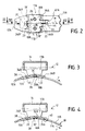
- two bosses, respectively 30 and 32 are formed projecting from the inner face of the strip, at the first end 10A of the latter, and thus each penetrate into the corresponding aperture. So, in Figure 3, we sees the aperture 26 into which the boss 30 enters, while FIG. 4 shows the aperture 28 into which the boss 32 enters.
- the fixing means from the housing to the band include two sets of longitudinal wedging each comprising an aperture and a boss associated therewith, these two assemblies being arranged on either side of the median longitudinal axis of the band M.
- Each of the bosses has a sharp edge, respectively 30A and 32A, which cooperates with an edge of the corresponding aperture.
- the sharp edge is facing away from the free end 10'A of the first end 10A of the strip in which the boss is carried which carries this free edge.
- the first end 10A of this the latter is stressed in tension with respect to the housing in the direction of the arrow F.
- the reaction effects of the case are therefore exerted on the free edge of the boss and the edge of the aperture with which it cooperates. So the necklace is reinforced without using solder points between the housing and the bandaged.
- the bosses 30 and 32 are both formed by punctures, which are achieved by a simple operation of pushing and shearing and which have the advantage of presenting the edges free previously mentioned.
- Openwork 26 and 28 are performed in mid-regions of the sole 18 of the housing, that is to say substantially equidistant from the edges front 18 'and rear 18 "of this sole.
- the bosses 30 and 32 are them spanned in a region of the first end 10A of the strip which is between windows 20 and 22 through which the legs of the fixing the housing and substantially equal distance from these windows.
- openings 26 and 28 and the bosses 30 and 32 are provided in regions of the sole of the housing and of the first end of the strip not otherwise affected by cuts or the like likely to locally reduce their mechanical strength.
- the cover 16 of the housing has an axial wall (in the direction of the length of the strip) which has the shape of a portion of cylinder to receive the screw 12. From this portion of cylinder extend wings 17A and 17B, each of them having a part which forms a side wall of the housing and an end portion, respectively 18A and 18B, which is folded against the inner face 11A of the strip.
- Part 18A of wing 17A has, substantially in the extension of its longitudinal end edge, a first tab 34A which extends towards the end 10'A of the strip and a second tab 36A which extends in the other direction.
- part 18B of the wing 17B has a first tab 34B and a second tab 36B.
- the two tabs 34A and 34B are juxtaposed in being separated by a cutout 31 which corresponds to the extension of the longitudinal edges of the two wings, as well as the two legs 36A and 36B are juxtaposed by being separated by a cutout 33.
- the two legs 34A and 34B pass through the window 20 to be arranged on the outside of the end 10A of the strip, as shown seen in Figures 3 and 4.
- the window 22 has a width only adapted to allow it to receive the tab 36B.
- This window is substantially interrupted on the median axis of the strip so that the strip remains full in the region in which it cooperates with tab 36A.
- window 22 through which only passes tab 36B.
- a routing 40 which forms a recess on the inner face of the strip.
- a projection 42 is produced in the region of the window 22 and of the plunge 40 .
- the tab 36A which remains on the inner side of the strip is housed in the recess formed under the groove 40 and is wedged laterally by the longitudinal edges of this plunge. This one is indeed not only made by stamping, but also by cutting longitudinal 41 at least on the side opposite window 22, allowing it to remain a sharp blocking edge 41A.
- Figures 6 and 7 show an alternative embodiment for fixing means.
- the bosses 30 and 32 similar to those of the previous figures, these bosses appearing in hollow in FIG. 6.
- the window 20 also has its front edge formed in a depression 38. This time, the projection 42 of FIG. 5 is absent, the face outside of the strip remaining on the same radius.
- the rear window 22 has a rear edge housed in a depression 44 formed in hollow on the outer face of the strip. So the leg 36B can be accommodated in the thickness of this depression so that that its outer face is on the same radius as the outer face of the strip portion 10A.
- a stamping 50 is formed along the edge longitudinal of the strip, on the other side of the median axis M of this strip from window 22. Viewed from the inside of the strip visible in Figure 7, the depressions 38 and 44 and the stamped 50 form bosses.
- the longitudinal edge 50A of the stamped 50 projecting from the face inside of the strip forms a sharp edge for longitudinal locking.
- the openings 26 and 28 are constituted by simple circular holes in the sole of the housing, respectively practiced in parts 18A and 18B of the wings 17A and 17B. These openings are made in a central region of these parts 18A and 18B.
- the punctures 30 and 32 are produced in such a way that their sheared edges 30 and 32A have a contour conforming to the shape of the edge of the openings, for example a partially circular outline.
Abstract
Description
La présente invention concerne un collier de serrage du type "à vis tangente", comprenant une bande de métal enroulée sur elle-même, une vis de serrage et un boítier fixé à une première extrémité de la bande.The present invention relates to a clamp type of "screw tangent ", comprising a metal band wound on itself, a screw clamp and a housing attached to a first end of the strip.
Le boítier comporte un capot disposé du côté extérieur de la bande et une semelle qui s'étend contre la face intérieure de la bande et qui est fixée à cette dernière par des moyens de fixation, lesdits moyens de fixation comprenant au moins une fenêtre pratiquée dans une première extrémité de la bande et au moins une patte ou extension qui est solidaire de la semelle du boítier et qui pénètre dans cette fenêtre, la vis ayant un fût fileté qui est engagé dans le capot, la deuxième extrémité de la bande étant susceptible d'être insérée dans le capot, entre le fût fileté de la vis et la première extrémité de la bande, le fût fileté de la vis étant susceptible de coopérer avec ladite deuxième extrémité pour serrer le collier.The housing has a cover disposed on the outside of the strip and a sole which extends against the inner face of the strip and which is fixed to the latter by fixing means, said fixing means comprising at least one window made in a first end of the band and at least one tab or extension which is integral with the sole of the housing and which enters this window, the screw having a threaded barrel which is engaged in the cover, the second end of the strip being susceptible to be inserted in the cover, between the threaded barrel of the screw and the first end of the strip, the threaded barrel of the screw being capable of cooperating with said second end to tighten the collar.
On connaít des colliers de serrage de ce type, par exemple par les documents GB 660 981, US 2 395 273. Dans la région des fenêtres pratiquées dans la première extrémité de la bande, la résistance de la bande à la traction et à la torsion est plus faible que dans les parties sensiblement pleines de cette bande.We know clamps of this type, for example by documents GB 660 981, US 2,395,273. In the window region practiced in the first end of the strip, the resistance of the strip in tension and in torsion is weaker than in the parts appreciably full of this band.
Lors du serrage du collier, une force de traction élevée s'exerce sur la bande. Les efforts de réaction à cette traction s'appliquent sur le boítier qui réagit sur la bande du collier dans la région des moyens de fixation de ce boítier à cette bande. Ces moyens de fixation sont donc fortement sollicités, en particulier lors du serrage du collier, sous l'effet des efforts de traction.When tightening the collar, a high tensile force is exerted on the bandaged. The reaction forces to this traction are applied to the housing which reacts on the band of the collar in the region of the fixing means of this case to this band. These fastening means are therefore highly stressed, in particular when tightening the collar, under the effect of tensile forces.
Lorsque ces moyens de fixation comprennent des fenêtres pratiquées dans la bande, ces dernières correspondent à une zone de fragilité de cette bande. Il en résulte un risque de détérioration du collier dans cette zone lorsque, en particulier lors du serrage, les efforts de traction sont élevés.When these fixing means comprise windows made in the band, these correspond to a zone of fragility of this bandaged. This results in a risk of deterioration of the collar in this area. when, in particular during tightening, the tensile forces are high.
On connaít par ailleurs des colliers de serrage de ce type, par exemple par le document US 3 351 989, pour lesquels des points de soudure sont en outre pratiqués entre le boítier et la bande pour renforcer le collier.We also know clamps of this type, for example by document US 3,351,989, for which solder points are also made between the housing and the band to strengthen the collar.
La présente invention s'applique à un collier à vis tangente et a pour but d'améliorer les moyens de fixation du boítier à la bande de ce collier pour mieux répartir les efforts de réaction dus aux forces de traction occasionnées par le serrage du collier et pour faire en sorte que ces efforts concernent une zone de la bande moins fragilisée. The present invention applies to a tangent screw collar and has for purpose of improving the means of fixing the housing to the band of this collar to better distribute the reaction forces due to the traction forces caused by the tightening of the collar and to ensure that these efforts relate to an area of the strip that is less fragile.
L'invention s'applique en particulier à des colliers de serrage à vis tangente dans lesquels les moyens de fixation du boítier par rapport à la bande comprennent au moins une fenêtre pratiquée dans la première extrémité de la bande et au moins une patte ou extension qui est solidaire de la semelle du boítier et qui pénètre dans cette fenêtre.The invention applies in particular to screw clamps tangent in which the means for fixing the housing relative to the strip include at least one window made in the first end of the strip and at least one tab or extension which is integral with the sole of the case and which enters this window.
Ce but est atteint grâce au fait que les moyens de fixation comportent au moins un ensemble de calage longitudinal comprenant un ajour pratiqué dans une région médiane de la semelle du boítier et un bossage, formé en saillie sur la face intérieure de la bande et pénétrant dans ledit ajour.This object is achieved thanks to the fact that the fixing means comprise at least one longitudinal wedging assembly comprising an openwork in a middle region of the sole of the housing and a boss, formed in projection on the inside of the strip and penetrating into said aperture.
Le bossage pratiqué dans la bande ne diminue pas sensiblement la résistance mécanique de cette dernière. Si il est de dimension réduite, il a même plutôt tendance à augmenter localement cette résistance. Le ou les ajours sont pratiqués dans une région médiane de la semelle et peuvent présenter des dimensions telles qu'ils affectent peu la résistance mécanique de cette dernière.The boss formed in the strip does not appreciably reduce the mechanical resistance of the latter. If it is of reduced size, it has even rather tend to locally increase this resistance. The openwork is practiced in a central region of the sole and can have dimensions such that they have little effect on mechanical strength of the latter.
Couramment, dans les colliers de serrage à vis tangente, la bande du collier est réalisée à partir d'un feuillard de faible épaisseur. Le métal qui constitue le boítier présente quant à lui une épaisseur légèrement supérieure et il est plus résistant. Par conséquent, le fait que l'ajour de l'ensemble de calage longitudinal soit pratiqué dans la semelle du boítier n'affecte pas la résistance mécanique de ce boítier dans des proportions telles qu'il pourrait en résulter un risque de détérioration du collier sous l'effet des efforts de traction normalement appliqués à ce collier lors de son serrage ou légèrement supérieurs à ces efforts "normaux".Commonly, in tangential screw clamps, the band of the necklace is made from a thin strip. The metal that is the case has a slightly greater thickness and it is more resistant. Therefore, the fact that the opening of the set of longitudinal wedging is practiced in the sole of the case does not affect the mechanical resistance of this case in proportions such that it could result in a risk of deterioration of the collar under the effect of the efforts of tension normally applied to this collar when tightening or slightly higher than these "normal" efforts.
Grâce aux dispositions de l'invention, les efforts de réaction à la traction sur la bande s'exercent principalement sur le ou les ensembles de calage longitudinal, avec une éventuelle répartition sur les autres éléments des moyens de fixation.Thanks to the provisions of the invention, the reaction efforts to the traction on the strip is exerted mainly on the set or sets of longitudinal setting, with possible distribution on the other elements fixing means.
Avantageusement, le bossage du ou de chaque ensemble de calage longitudinal comporte un bord vif orienté à l'opposé de l'extrémité libre de la première extrémité de la bande et coopérant avec le bord de l'ajour correspondant situé en vis-à-vis.Advantageously, the boss of the or each wedging assembly longitudinal has a sharp edge facing away from the free end of the first end of the strip and cooperating with the edge of the opening correspondent located opposite.
Le bord vif du bossage coopère en butée avec le bord de l'ajour correspondant sans aucun risque de glissement relatif, même sous l'effet d'efforts de traction élevés. The sharp edge of the boss cooperates in abutment with the edge of the aperture without any risk of relative slippage, even under the effect high tensile forces.
Ce bossage est avantageusement formé par un crevé, c'est-à-dire par un picot repoussé sur la face intérieure de la bande jusqu'à son cisaillage partiel par rapport à cette bande, le bord cisaillé formant le bord vif évoqué ci-dessus.This boss is advantageously formed by a puncture, that is to say by a pin pushed back on the inside of the strip until it shears partial to this strip, the sheared edge forming the sharp edge mentioned above.
Selon une disposition avantageuse, le collier comporte deux ensembles de calage longitudinal disposés de part et d'autre d'un axe longitudinal médian de la bande.According to an advantageous arrangement, the collar comprises two longitudinal setting assemblies arranged on either side of an axis longitudinal median of the strip.
Ainsi, les efforts de traction se répartissent de manière sensiblement homogène sur chacun des deux ensembles de calage longitudinal.Thus, the tensile forces are distributed appreciably homogeneous on each of the two sets of longitudinal setting.
L'invention sera bien comprise et ses avantages apparaítront mieux à la lecture de la description détaillée qui suit, d'un mode de réalisation représenté à titre d'exemple non limitatif. La description se réfère aux dessins annexés, sur lesquels :
- la figure 1 est une vue partielle de côté d'un collier à vis auquel s'applique l'invention,
- la figure 2 est une vue de dessous, prise selon la flèche II de la figure 1, montrant seulement la première extrémité de la bande munie du boítier,
- les figures 3 et 4 sont des coupes respectivement prises selon les lignes III-III et IV-IV de la figure 2,
- la figure 5 montre, en perspective, la première extrémité de la bande avant la fixation du boítier sur cette dernière.
- la figure 6 montre, selon une variante de réalisation, la face extérieure de la première extrémité de la bande, et
- la figure 7 est une vue en perspective de la variante de la figure 6, sur laquelle la face intérieure de la bande est tournée vers le haut.
- FIG. 1 is a partial side view of a screw collar to which the invention applies,
- FIG. 2 is a bottom view, taken along the arrow II in FIG. 1, showing only the first end of the strip provided with the housing,
- FIGS. 3 and 4 are sections respectively taken along lines III-III and IV-IV of FIG. 2,
- Figure 5 shows, in perspective, the first end of the strip before fixing the housing on the latter.
- FIG. 6 shows, according to an alternative embodiment, the external face of the first end of the strip, and
- Figure 7 is a perspective view of the variant of Figure 6, on which the inner face of the strip is turned upwards.
Le collier de la figure 1 comporte une bande de métal 10 enroulée sur
elle-même, dont seules les parties d'extrémité 10A et 10B sont représentées.
Le collier comporte une vis de serrage 12 disposée dans un boítier 14, qui
comporte un capot 16 s'étendant du côté extérieur du collier et une semelle
18, fixée à la première extrémité 10A et la bande et disposée contre la face
intérieure 11A de cette dernière. La vis 12 présente une tête de vissage 12A
disposée à l'extérieur du capot 16 et un fût fileté 12B, indiqué en trait
interrompu, qui s'étend à l'intérieur de ce capot. The collar of Figure 1 has a
On considère que la direction allant vers l'intérieur est celle qui est dirigée vers le centre du cercle formé par l'enroulement de la bande sur le collier.We consider that the direction going inward is that which is directed towards the center of the circle formed by the winding of the strip on the necklace.
La première extrémité 10B de la bande est insérée dans le capot,
entre la face extérieure 11B de la bande et le fût fileté de la vis.The
Classiquement, au moins la deuxième extrémité 10B de la bande est
pourvue de surfaces d'appui (fentes ou reliefs) en crémaillère, avec
lesquelles les filets de la vis sont aptes à coopérer lors du vissage de cette
dernière dans le sens R pour serrer le collier.Conventionally, at least the
Sur la figure 2, on voit que les moyens de fixation du boítier par
rapport à la bande comprennent deux fenêtres, 20 et 22, qui sont pratiquées
dans la bande et qui sont espacées longitudinalement l'une de l'autre, ainsi
que des pattes qui forment des prolongements longitudinaux de la semelle
du boítier et qui sont engagées dans ces fenêtres, de manière à apparaítre sur
la face extérieure 11B de la bande. L'espacement longitudinal des fenêtres
20 et 22 est sensiblement égal à la longueur que présente le boítier dans la
zone de ce dernier qui est dépourvue des extensions.In Figure 2, we see that the means of fixing the housing by
compared to the strip include two windows, 20 and 22, which are practiced
in the strip and which are spaced longitudinally from each other, thus
only legs which form longitudinal extensions of the sole
of the case and which are engaged in these windows, so as to appear on
the
Ainsi, les moyens de fixation comprennent deux ensembles de fixation respectivement disposés de part et d'autre d'une région T de la semelle transversale à la bande.Thus, the fixing means comprise two sets of fixation respectively arranged on either side of a region T of the sole transverse to the band.
Deux ajours, respectivement 26 et 28, sont pratiqués dans une région
médiane de la semelle 18 du boítier. Comme on le voit mieux sur les figures
3 et 4. deux bossages, respectivement 30 et 32, sont formés en saillie sur la
face intérieure de la bande, à la première extrémité 10A de cette dernière, et
pénètrent ainsi chacun dans l'ajour correspondant. Ainsi, sur la figure 3, on
voit l'ajour 26 dans lequel pénètre le bossage 30, tandis que la figure 4
montre l'ajour 28 dans lequel pénètre le bossage 32. Les moyens de fixation
du boítier à la bande comprennent deux ensembles de calage longitudinal
comprenant chacun un ajour et un bossage qui lui est associé, ces deux
ensembles étant disposés de part et d'autre de l'axe longitudinal médian de la
bande M.Two openings, respectively 26 and 28, are practiced in a region
median of the sole 18 of the case. As best seen in the figures
3 and 4. two bosses, respectively 30 and 32, are formed projecting from the
inner face of the strip, at the
Chacun des bossages présente un bord vif, respectivement 30A et
32A, qui coopère avec un bord de l'ajour correspondant. Le bord vif est
tourné du côté opposé à l'extrémité libre 10'A de la première extrémité 10A
de la bande dans laquelle est pratiqué le bossage qui porte ce bord libre. En
effet, lors du serrage de la bande, la première extrémité 10A de cette
dernière est sollicitée en traction par rapport au boítier dans le sens de la
flèche F. Les effets de réaction du boítier s'exercent donc sur le bord libre
du bossage et le bord de l'ajour avec lequel il coopère. Ainsi, le collier est
renforcé sans avoir recours à des points de soudure entre le boítier et la
bande.Each of the bosses has a sharp edge, respectively 30A and
32A, which cooperates with an edge of the corresponding aperture. The sharp edge is
facing away from the free end 10'A of the
Dans l'exemple avantageux représenté, les bossages 30 et 32 sont
tous deux formés par des crevés, qui sont réalisés par une simple opération
de repoussage et de cisaillage et qui ont l'avantage de présenter les bords
libres précédemment évoqués.In the advantageous example shown, the
Ces bords vifs sont cisaillés sur une petite partie du pourtour des bossages, par exemple sur 1/4 de tour ou 1/3 de tour, pour éviter que les crevés n'aient tendance à se replier sous l'effet d'efforts de traction élevés.These sharp edges are sheared over a small part of the periphery of the bosses, for example on 1/4 turn or 1/3 turn, to prevent punctured do not tend to fold under the effect of high tensile forces.
Les ajours 26 et 28 sont pratiqués dans des régions médianes de la
semelle 18 du boítier, c'est-à-dire sensiblement à égale distance des bords
avant 18' et arrière 18" de cette semelle. Les bossages 30 et 32 sont quant à
eux ménagés dans une région de la première extrémité 10A de la bande qui
se trouve entre les fenêtres 20 et 22 à travers lesquelles passent les pattes de
fixation du boítier et sensiblement à égale distance de ces fenêtres.
Ainsi, les ajours 26 et 28 et les bossages 30 et 32 sont ménagés dans
des régions de la semelle du boítier et de la première extrémité de la bande
non affectées autrement par des découpes ou analogues de nature à
diminuer localement leur résistance mécanique.Thus, the
Le capot 16 du boítier présente une paroi axiale (dans le sens de la
longueur de la bande) qui a la forme d'une portion de cylindre pour recevoir
la vis 12. A partir de cette portion de cylindre, s'étendent des ailes 17A et
17B, chacune d'entre elles ayant une partie qui forme une paroi latérale du
boítier et une partie d'extrémité, respectivement 18A et 18B, qui est repliée
contre la face intérieure 11A de la bande.The
Ces parties d'extrémité 18A et 18B forment, à elles deux, la semelle
18. Les bords longitudinaux d'extrémité de ces ailes sont placés bord à bord
comme l'indique la ligne 19 de la figure 2.These
Les extensions de la semelle pénétrant dans les fenêtres 20 et 22 sont
réalisées de la manière suivante. La partie 18A de l'aile 17A présente,
sensiblement dans le prolongement de son bord longitudinal d'extrémité,
une première patte 34A qui s'étend vers l'extrémité 10'A de la bande et une
deuxième patte 36A qui s'étend dans l'autre sens. De même, la partie 18B de
l'aile 17B présente une première patte 34B et une deuxième patte 36B.The sole
Ainsi, lorsque les parties 18A et 18B des ailes sont repliées contre la
face intérieure de la bande, les deux pattes 34A et 34B sont juxtaposées en
étant séparées par une découpe 31 qui correspond au prolongement des
bords longitudinaux des deux ailes, de même que les deux pattes 36A et
36B sont juxtaposées en étant séparées par une découpe 33.Thus, when the
Les deux pattes 34A et 34B passent à travers la fenêtre 20 pour être
disposées du côté extérieur de l'extrémité 10A de la bande, comme on le
voit sur les figures 3 et 4. On pourrait également prévoir que, du côté arrière
de la semelle du boítier, les deux pattes 36A et 36B passent à travers la
fenêtre 22, dont les dimensions seraient sensiblement égales à celle de la
fenêtre 20, pour venir se placer du côté extérieur de la bande.The two
Toutefois, selon la variante avantageuse représentée, seule la patte
36B passe dans la fenêtre 22, tandis que la patte 36A est, comme le reste de
la partie 18A de la semelle, située contre la face intérieure 11A. En effet, la
fenêtre 22 a une largeur seulement adaptée à lui permettre de recevoir la
patte 36B. Cette fenêtre s'interrompt sensiblement sur l'axe médian de la
bande de telle sorte que la bande reste pleine dans la région dans laquelle
elle coopère avec la patte 36A.However, according to the advantageous variant shown, only the
Cette variante avantageuse permet d'éviter la tendance au
basculement du boítier par rapport à la bande lors du serrage du collier. En
effet, sous l'action du couple de serrage, une partie du mouvement de
rotation de la vis est transformée en une force de traction qui serre le collier,
tandis qu'une autre partie donne, sous l'effet des frottements, un couple qui a
tendance à faire tourner le collier autour de l'axe de la vis. Lorsque la liaison
entre le boítier et la bande est soumise à ce couple parasite, appelé "couple
de renversement", la patte 36A fournit un effort de réaction contre la face
intérieure de la bande repoussant d'autant la limite du basculement.This advantageous variant makes it possible to avoid the tendency to
tilting of the housing relative to the band when tightening the collar. In
effect, under the action of the tightening torque, part of the movement of
rotation of the screw is transformed into a tensile force which tightens the collar,
while another part gives, under the effect of friction, a couple which has
tendency to rotate the collar around the axis of the screw. When the bond
between the housing and the band is subjected to this parasitic torque, called "couple
tip ", the
Sur la figure 5, on voit en perspective la première extrémité 10A de
la bande, du côté extérieur de cette dernière. On distingue ainsi les faces
extérieures des éléments qui forment les bossages 30 et 32. A l'avant de ces
bossages, c'est-à-dire entre lesdits bossages et l'extrémité libre 10'A, se
trouve la fenêtre 20 qui reçoit les deux pattes 34A et 34B. Le bord avant de
cette fenêtre est ménagé dans une légère dépression 38 qui permet que les
pattes 34A et 34B se trouvent du côté extérieur de la bande tout en restant
sensiblement au niveau de la face extérieure de ladite bande.In Figure 5, we see in perspective the
A l'arrière des bossages 30 et 32, se trouve la fenêtre 22 à travers
laquelle passe seulement la patte 36B. A côté de cette fenêtre est ménagé un
soyage 40 qui forme un renfoncement sur la face intérieure de la bande.
Dans la région de la fenêtre 22 et du soyage 40 est réalisé un ressaut 42.
Ainsi, l'épaisseur de la semelle 18 du boítier peut être logée dans la hauteur
de ce ressaut, c'est-à-dire que la face intérieure de cette semelle se trouve
sensiblement sur le même rayon que la face intérieure 11A de la bande
lorsque le collier est fermé. La patte 36A qui reste du côté intérieur de la
bande est logée dans le renfoncement formé sous le soyage 40 et est calée
latéralement par les bords longitudinaux de ce soyage. Celui-ci est en effet
non seulement réalisé par emboutissage, mais également par une découpe
longitudinale 41 au moins du côté opposé à la fenêtre 22, laissant subsister
un bord vif de blocage 41A.At the rear of
Les figures 6 et 7 montrent une variante de réalisation pour les
moyens de fixation. On reconnaít sur ces figures les bossages 30 et 32
analogues à ceux des figures précédentes, ces bossages apparaissant en
creux sur la figure 6. La fenêtre 20 a également son bord avant formé dans
une dépression 38. Cette fois, le ressaut 42 de la figure 5 est absent, la face
extérieure de la bande restant sur un même rayon.Figures 6 and 7 show an alternative embodiment for
fixing means. We recognize in these figures the
Toutefois, la fenêtre arrière 22 présente un bord arrière logé dans une
dépression 44 formée en creux sur la face extérieure de la bande. Ainsi, la
patte 36B peut se loger dans l'épaisseur de cette dépression de telle sorte
que sa face extérieure se trouve sur le même rayon que la face extérieure de
la portion de bande 10A. Un embouti 50 est formé le long du bord
longitudinal de la bande, de l'autre côté de l'axe médian M de cette bande
par rapport à la fenêtre 22. Considérés depuis la face intérieure de la bande
visible sur la figure 7, les dépressions 38 et 44 et l'embouti 50 forment des
bossages. Le bord longitudinal 50A de l'embouti 50 en saillie sur la face
intérieure de la bande forme un bord vif de blocage longitudinal. Ainsi, la
patte 36A de la semelle du boítier qui reste disposée contre la face intérieure
de la bande est parfaitement calée entre le bossage formé par la dépression
44 et ce bord vif 50A. L'espace libre ménagé sur cette face entre l'embouti
50 et la dépression 44 forme donc, comme sur la figure 5, un soyage qui
reçoit la patte 36A. However, the
Dans l'exemple avantageux représenté, les ajours 26 et 28 sont
constitués par de simples perçages circulaires de la semelle du boítier,
respectivement pratiqués dans les parties 18A et 18B des ailes 17A et 17B.
Ces ajours sont réalisés dans une région centrale de ces parties 18A et 18B.
Les crevés 30 et 32 sont réalisés de telle sorte que leurs bords cisaillés 30 et
32A présentent un contour épousant la forme du bord des ajours, par
exemple un contour partiellement circulaire.In the advantageous example shown, the
Claims (8)
caractérisé en ce que les moyens de fixation comportent, en outre, au moins un ensemble de calage longitudinal comprenant un ajour (26, 28) pratiqué dans une région médiane de la semelle (18) du boítier (14) et un bossage (30, 32), formé en saillie sur la face intérieure (11A) de la bande et pénétrant dans ledit ajour.Clamp comprising a metal strip (10) wound on itself, a clamping screw (12) and a housing (14) fixed to a first end of the strip (10A), this housing having a cover arranged on the side outside of the strip and a sole (18) which extends against the internal face (11A) of the strip and which is fixed to the latter by fixing means, said fixing means comprising at least one window (20, 22 ) made in the first end (10A) of the strip (10) and at least one tab or extension (34A, 34B, 36B) which is integral with the sole (18) of the housing (14) and which enters this window, the screw having a threaded barrel (12B) which is engaged in the cover (16), the second end (10B) of the strip (10) being capable of being inserted in the cover, between the threaded barrel (12B) of the screw and the first end (10A) of the strip, the threaded barrel of the screw being capable of cooperating with said d second end (10B) for tightening the collar,
characterized in that the fixing means further comprise at least one longitudinal wedging assembly comprising an aperture (26, 28) formed in a median region of the sole (18) of the housing (14) and a boss (30, 32), formed projecting from the inner face (11A) of the strip and penetrating said opening.
Applications Claiming Priority (2)
| Application Number | Priority Date | Filing Date | Title |
|---|---|---|---|
| FR9911340A FR2798429B1 (en) | 1999-09-10 | 1999-09-10 | TANGENT SCREW CLAMP |
| FR9911340 | 1999-09-10 |
Publications (1)
| Publication Number | Publication Date |
|---|---|
| EP1083376A1 true EP1083376A1 (en) | 2001-03-14 |
Family
ID=9549715
Family Applications (1)
| Application Number | Title | Priority Date | Filing Date |
|---|---|---|---|
| EP00402477A Withdrawn EP1083376A1 (en) | 1999-09-10 | 2000-09-08 | Worm drive clamp |
Country Status (2)
| Country | Link |
|---|---|
| EP (1) | EP1083376A1 (en) |
| FR (1) | FR2798429B1 (en) |
Cited By (2)
| Publication number | Priority date | Publication date | Assignee | Title |
|---|---|---|---|---|
| EP1158235A2 (en) * | 2000-05-25 | 2001-11-28 | Rasmussen GmbH | Worm drive clamp |
| ES2415249A1 (en) * | 2013-03-27 | 2013-07-24 | Grupo Mikalor, S.L. | Clamp (Machine-translation by Google Translate, not legally binding) |
Citations (4)
| Publication number | Priority date | Publication date | Assignee | Title |
|---|---|---|---|---|
| FR928736A (en) * | 1944-10-25 | 1947-12-05 | Worm screw clamp | |
| FR1276008A (en) * | 1960-07-29 | 1961-11-17 | Advanced hose clamp | |
| US3351989A (en) * | 1966-12-05 | 1967-11-14 | Sterling Automotive Mfg Co Inc | Hose clamp |
| EP0976960A1 (en) * | 1998-07-29 | 2000-02-02 | Serflex | Worm drive clamp |
Family Cites Families (2)
| Publication number | Priority date | Publication date | Assignee | Title |
|---|---|---|---|---|
| GB660981A (en) | 1944-08-10 | 1951-11-14 | Michael Thomas Usborne Collier | Improvements in or relating to hose clips or clamps |
| US2395275A (en) | 1944-11-22 | 1946-02-19 | Jackson Arch Robert | Collapsible child's cart |
-
1999
- 1999-09-10 FR FR9911340A patent/FR2798429B1/en not_active Expired - Lifetime
-
2000
- 2000-09-08 EP EP00402477A patent/EP1083376A1/en not_active Withdrawn
Patent Citations (4)
| Publication number | Priority date | Publication date | Assignee | Title |
|---|---|---|---|---|
| FR928736A (en) * | 1944-10-25 | 1947-12-05 | Worm screw clamp | |
| FR1276008A (en) * | 1960-07-29 | 1961-11-17 | Advanced hose clamp | |
| US3351989A (en) * | 1966-12-05 | 1967-11-14 | Sterling Automotive Mfg Co Inc | Hose clamp |
| EP0976960A1 (en) * | 1998-07-29 | 2000-02-02 | Serflex | Worm drive clamp |
Cited By (3)
| Publication number | Priority date | Publication date | Assignee | Title |
|---|---|---|---|---|
| EP1158235A2 (en) * | 2000-05-25 | 2001-11-28 | Rasmussen GmbH | Worm drive clamp |
| EP1158235A3 (en) * | 2000-05-25 | 2003-01-02 | Rasmussen GmbH | Worm drive clamp |
| ES2415249A1 (en) * | 2013-03-27 | 2013-07-24 | Grupo Mikalor, S.L. | Clamp (Machine-translation by Google Translate, not legally binding) |
Also Published As
| Publication number | Publication date |
|---|---|
| FR2798429B1 (en) | 2001-11-30 |
| FR2798429A1 (en) | 2001-03-16 |
Similar Documents
| Publication | Publication Date | Title |
|---|---|---|
| EP3026316B1 (en) | Hinged clamping collar | |
| EP3157837B1 (en) | Band clamp comprising a through-hoop and clamping tool | |
| EP2310734B1 (en) | Tightening device with collar | |
| FR2884563A1 (en) | CLAMPING DEVICE WITH REINFORCED CLAMPING EARS | |
| EP1963688A1 (en) | Arrangement for assembling two parts by screw-fastening using a screw-nut system | |
| EP2789888B1 (en) | Clamping device for tight coupling of unprofiled tubes | |
| WO1998043010A1 (en) | Ring clamp for connecting two tubes | |
| EP3670988B1 (en) | Clamping device comprising a belt and a sealing ring | |
| EP3157836A1 (en) | Band clamp comprising a through-hoop | |
| FR2794517A1 (en) | DEVICE FOR THE SEALED CONNECTION OF TWO SMOOTH TUBES | |
| EP1540229B1 (en) | Clamping ring | |
| EP1702693B1 (en) | Tool chuck for a rotating machine | |
| EP1156896B1 (en) | Crimping ring and method for making same | |
| FR2521656A1 (en) | DEVICE FOR FIXING THE TWO WINGS OF A CRANKSET FOR A BICYCLE | |
| EP0780268B1 (en) | Fixing system for a car liner | |
| EP1083376A1 (en) | Worm drive clamp | |
| FR2974879A1 (en) | TIGHTENING NECKLACE WITH HINGE | |
| EP0208582B1 (en) | Winding shaft, in particular for a safety belt | |
| EP0976960B1 (en) | Worm drive clamp | |
| FR2576140A1 (en) | Retention arrangement for covers of automatic switches | |
| EP0416981A1 (en) | Adjustable rod, particularly for the steering linkage of a motor vehicle | |
| FR2503806A1 (en) | Fastener for automobile lining panels - has spring-loaded bolt and cotter plate locked in position by internal projections | |
| FR2543628A1 (en) | Device for the blind stapling of two components, especially for motor vehicle metal sheets | |
| FR2662474A1 (en) | Dismantleable fast nut | |
| FR2532376A1 (en) | Rapid fastener for panels |
Legal Events
| Date | Code | Title | Description |
|---|---|---|---|
| PUAI | Public reference made under article 153(3) epc to a published international application that has entered the european phase |
Free format text: ORIGINAL CODE: 0009012 |
|
| AK | Designated contracting states |
Kind code of ref document: A1 Designated state(s): DE ES GB IT PT |
|
| AX | Request for extension of the european patent |
Free format text: AL;LT;LV;MK;RO;SI |
|
| 17P | Request for examination filed |
Effective date: 20010910 |
|
| AKX | Designation fees paid |
Free format text: DE ES GB IT PT |
|
| GRAH | Despatch of communication of intention to grant a patent |
Free format text: ORIGINAL CODE: EPIDOS IGRA |
|
| STAA | Information on the status of an ep patent application or granted ep patent |
Free format text: STATUS: THE APPLICATION IS DEEMED TO BE WITHDRAWN |
|
| 18D | Application deemed to be withdrawn |
Effective date: 20031028 |