EP2479679A2 - Computersystem und Verfahren zur Übernahme eines HBA-Identifizierers auf einer PCI-Karte - Google Patents
Computersystem und Verfahren zur Übernahme eines HBA-Identifizierers auf einer PCI-Karte Download PDFInfo
- Publication number
- EP2479679A2 EP2479679A2 EP11194133A EP11194133A EP2479679A2 EP 2479679 A2 EP2479679 A2 EP 2479679A2 EP 11194133 A EP11194133 A EP 11194133A EP 11194133 A EP11194133 A EP 11194133A EP 2479679 A2 EP2479679 A2 EP 2479679A2
- Authority
- EP
- European Patent Office
- Prior art keywords
- identifier
- hba
- pcie switch
- pci card
- server
- Prior art date
- Legal status (The legal status is an assumption and is not a legal conclusion. Google has not performed a legal analysis and makes no representation as to the accuracy of the status listed.)
- Withdrawn
Links
Images


Classifications
-
- G—PHYSICS
- G06—COMPUTING OR CALCULATING; COUNTING
- G06F—ELECTRIC DIGITAL DATA PROCESSING
- G06F13/00—Interconnection of, or transfer of information or other signals between, memories, input/output devices or central processing units
- G06F13/38—Information transfer, e.g. on bus
- G06F13/382—Information transfer, e.g. on bus using universal interface adapter
- G06F13/385—Information transfer, e.g. on bus using universal interface adapter for adaptation of a particular data processing system to different peripheral devices
-
- G—PHYSICS
- G06—COMPUTING OR CALCULATING; COUNTING
- G06F—ELECTRIC DIGITAL DATA PROCESSING
- G06F2213/00—Indexing scheme relating to interconnection of, or transfer of information or other signals between, memories, input/output devices or central processing units
- G06F2213/0024—Peripheral component interconnect [PCI]
-
- G—PHYSICS
- G06—COMPUTING OR CALCULATING; COUNTING
- G06F—ELECTRIC DIGITAL DATA PROCESSING
- G06F2213/00—Indexing scheme relating to interconnection of, or transfer of information or other signals between, memories, input/output devices or central processing units
- G06F2213/0052—Assignment of addresses or identifiers to the modules of a bus system
Definitions
- the present invention relates to a computer system for managing an HBA identifier of a PCI card mounted in an IO slot expansion unit serving as a constituent member of the computer system, and a method for inheriting the HBA identifier of the PCI card.
- a computer system which is formed so that a server chassis capable of being loaded with server blades of arithmetic system devices each composed of a CPU, a memory, etc. and an IO slot expansion unit capable of being loaded with PCI cards such as FC (Fibre Channel) PCI cards, Ethernet PCI cards, etc. are connected to each other by a PCIe cable.
- the IO slot expansion unit is further loaded with a PCIe switch. When setting of the PCIe switch is edited, connection between the server blades and the PCI cards can be switched.
- Patent Document 1 As the background art in this technical field, there is JP-A-2009-245455 (Patent Document 1). In this official gazette, "setting of disk mapping" has been described in terms of connection setting of LUs. In JP-A-2010-39729 (Patent Document 2), there has been disclosed a multi-route PCIe switch server system with the server chassis described as “server device” and the IO slot expansion unit described as “external I/O device”.
- the HBA identifier (which corresponds to a WWN if the PCI card is an FC PCI card or an MAC etc. if the PCI card is an Ethernet PCI card) of the PCI card before the replacement varies from the HBA identifier of the PCI card after the replacement. For this reason, after replacement of the PCI card has occurred, it is necessary that a user should register the HBA identifier of the PCI card newly in a device connected to the PCI card. There is however a problem that much labor and time is taken for such new registration work.
- the invention provides a computer system and an HBA identifier inheriting method.
- a PCIe switch register update control portion of an IO slot expansion unit controller in the IO slot expansion unit copies an identifier allocation table from the IO slot expansion unit controller to an identifier storage area of a PCIe switch register as soon as the IO slot expansion unit is powered on.
- an HBA identifier update control portion of an interface of the server acquires the identifier allocation table copied to the identifier storage area of the PCIe switch register through the PCIe cable as soon as the server is powered on.
- the HBA identifier update control portion stores the acquired identifier allocation table in a storage portion of the server.
- the HBA identifier update control portion refers to an identifier allocated in accordance with a PCI card slot and an HBA port on a PCI card from the identifier allocation table stored in the storage portion.
- the HBA identifier update control portion updates an identifier recorded in an identifier area of an HBA to the allocated identifier referred to from the identifier allocation table stored in the storage portion.
- a PCI card's HBA identifier table is read from the IO slot expansion unit controller (IO Drawer Controller, hereinafter referred to as IODC) in the IO slot expansion unit and recorded on the PCIe switch register of the PCIe switch.
- IODC IO Drawer Controller
- the EFI reads the HBA identifier table recorded on the PCIe switch register and updates the HBA identifier of the HBA mounted on the PCI card.
- the HBA mounted on the PCI card operates with the updated HBA identifier of the PCI card.
- the PCI card after the replacement can operate with the same HBA identifier as that before the replacement. Accordingly, a user does not have to register the HBA identifier of the PCI card newly in a device connected to the PCI card.
- Fig. 1 shows a system configuration diagram of a computer system to which the invention is applied.
- the system according to Embodiment 1 includes a server chassis 101, and an IO slot expansion unit 111.
- the server chassis 101 includes a server blade 102, and an SVP 103 serving as a server chassis management controller.
- the server blade 102 and the SVP 103 are connected to each other.
- the SVP 103 has a built-in memory which stores programs and data, and a built-in CPU which executes the programs.
- a CPU 107, a memory 108, an EFI 104, and a BMC 105 which is a server blade management controller are mounted in the server blade 102.
- the server blade 102 is connected to a server chassis PCIe port 106.
- the IO slot expansion unit 111 includes an IODC 112 serving as an IO slot expansion unit management controller, a PCIe switch 113, and PCI card slots 118.
- PCI cards 114 can be mounted in the PCI card slots 118 respectively.
- the IODC 112 and the PCIe switch 113 are connected to each other so as to be able to communicate with each other.
- the PCIe switch 113 is connected to each of the PCI card slots 118 by PCIe.
- the IODC has a built-in memory which stores programs and data, and a built-in CPU which executes the programs.
- the PCIe switch 113 and an IO slot expansion unit PCIe port 116 are connected to each other.
- Step 701 activation of the IODC 112 is started with powering on the IO slot expansion unit 111 as a trigger.
- Step 711 operation of the PCIe switch register update control portion 302 is started with starting the activation of the IODC as a trigger.
- Step 712 the PCIe switch register update control portion 302 acquires a WWN allocation table 301 recorded on the IODC.
- Step 713 the PCIe switch register update control portion 302 copies information of the WWN allocation table acquired in Step 712 to the WWN storage area 202 of the PCIe switch register 201.
- Step 714 the operation of the PCIe switch register update control portion 302 is terminated.
- Step 702 the activation of the IODC is completed.
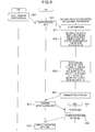
- Fig. 8 shows a flow chart of activation of the system.
- Step 801 the BMC starts powering on the server blade.
- the BMC starts powering on the server blade. For example, user operation, schedule, or the like, is assumed as a trigger for the BMC to start powering on the server blade.
- Step 811 activation of the EFI 104 is started with starting powering on the server blade in Step 801 as a trigger. Since the server blade is powered on, the EFI 104 on the server blade 102 is enabled to refer to the PCIe switch register 201 of the PCIe switch 113 and control the HBA's 115-1 and 115-2 of the PCI cards 114-1 and 114-2 through the PCIe switch 113.
- Step 821 operation of the HBA WWN update control portion 501 as one functional portion of the EFI 104 is started with starting the activation of the EFI in Step 811 as a trigger.
- the HBA WWN update control portion 501 reads the WWN allocation table copied to the WWN storage area 202 from the IODC 112 by referring to the PICe switch register 201 of the PICe switch 113 in the IO slot expansion unit 111 through the PCIe cable.
- the WWN allocation table read from the WWN storage area 202 is stored in the memory 108 of the server blade 102.
- the HBA WWN update control portion 501 refers to an allocated WWN corresponding to the PCI card slot identifier and the number of the HBA port 117 on the PCI card, from the WWN allocation table stored in the memory 108 of the server blade 102.
- the HBA WWN update control portion 501 updates a WWN of the HBA port recorded on the WWN area 401 of the HBA 115-1 to the allocated WWN referred to, through the HBA 115-1.
- the HBA WWN update control portion 501 also updates another allocated WWN for the HBA 115-2 in the same manner as that for the HBA 115-1.
- Step 824 the operation of the HBA WWN update control portion 501 is completed.
- Step 812 the EFI 104 issues a request to activate the HBA 115-1.
- the EFI 104 also issues a request to activate the HBA 115-2 in the same manner.
- Steps 831 and 832 activation of the HBA 115-1 is started upon reception of the HBA activating request issued from the EFI 104, and then the activation of the HBA 115-1 is completed.
- the HBA 115-1 reads the WWN area 401 of the HBA 115-1 and operates with the WWN updated in Step 823.
- the EFI 104 makes operation for the HBA 115-2 in the same manner.
- Step 813 the activation of the EFI 104 is completed.
- the identifier for the HBA port of each PCI card (which corresponds to the WWN if the PCI card is an FC PCI card or to an MAC etc. if the PCI card is an Ethernet PCI card) after occurrence of the failure varies from that before occurrence of the failure. For this reason, it is necessary to register the HBA identifier of the PCI card 114-1 or 114-2 newly in a device connected to the PCI card.
- a blade server of a background-art system having no IO slot expansion unit 111 that is, a blade server having a server blade, an SVP and PCI cards in a server chassis
- the SVP holds a WWN allocation table.
- a BMC in the server blade refers to the WWN allocation table held in the SVP
- an EFI in the server blade acquires the WWN allocation table through the BMC, so that the same WWN as that before replacement is allocated to the HBA of the PCI card after replacement.
- the WWN table needs to have an estimated maximum number of WWN's allocated to the IO slot expansion unit to be connected to the server chassis 101. Consequently, an unnecessary large number of WWN's are required.
- the WWN allocation table 301 is not held in the SVP 103 but held in the IODC 112 in the IO slot expansion unit 111 and copied from the IODC 112 to the PCIe switch register 201 of the PCIe switch 113.
- the EFI 104 in the server chassis 101 is formed to be allowed to refer to the WWN allocation table copied to the WWN storage area 202 of the PCIe switch register 201 through the PCIe cable.
- the EFI 104 updates the WWN of each PCI card 114 with powering on the server blade 102 as a trigger.
- the HBA of the new PCI card 114 inherits the same WWN as that of the HBA of the PCI card before replacement and operates with the inherited WWN as long as the new PCI card 114 is mounted in the same PCI card slot 118 in the IO slot expansion unit 111.
- LU connection setting for a FC-connected storage is a setting example in which setting can be dispensed with.
- the LU connection setting means registration of the WWN of a HBA connected in accordance with each LU.
- the HBA and the WWN also change so that the LU connection setting has to be edited correspondingly.
- it is not necessary to edit the LU connection setting because the WWN does not change even if the HBA changes.
- FC WWN is taken as an example of the HBA identifier in the embodiment, the same thing can be achieved easily when an Ethernet (registered trademark) MAC or the like is used as another example of the HBA identifier.
- Fig. 9 is an overall diagram showing Embodiment 2 of the invention.
- Embodiment 2 is different from Embodiment 1 in that a PCIe switch 901 in an IO slot expansion unit is a multi-route switch capable of being connected to a plurality of server blades 102, in place of a single-route switch connected to one server blade. Because the PCIe switch 901 is a multi-route switch, PCIe ports 116-1 and 116-2 are provided in the IO slot expansion unit and connected to different server blades respectively.
- Fig. 10 is a functional block diagram of the multi-route PCIe switch.
- the PCIe switch in Fig. 10 is different from the PCIe switch in Fig. 2 in that the PCIe switch in Fig. 10 has a multi-route switch control portion 1002, and that multi-route PCIe switch connection information 1001 is added to the PCIe switch register.
- the multi-route PCIe switch connection information 1001 means connection setting information of one single PCI card slot 118 or a plurality of PCI card slots 118 to all the PCIe ports 116 in the IO slot expansion unit. By the multi-route PCIe switch, PCI card slots can be connected to each PCIe port. As for the PCIe switch connection information 1001 in Fig. 11 , a plurality of connection PCI card slot identifiers 1102 can be held for each PCIe port identifier 1101 in the IO slot expansion unit.
- the multi-route switch control portion 1002 performs control for switching connection between the PCIe ports and the PCI card slots based on the multi-route PCIe switch connection information 1001.
- Fig. 11 shows connection information of the multi-route PCIe switch.
- the connection information is provided as a table having PCIe port identifiers 1101 in the IO slot expansion unit and corresponding connection PCI card slot identifiers 1102.
- the multi-route PCIe switch connection information is created by a user through the IODC 112.
- a flow chart of activation of the IO slot expansion unit in the multi-route PCIe switch is the same as that in the single-route PCIe switch ( Fig. 7 ) in Embodiment 1.
- Fig. 12 is a flow chart of activation of the system in the multi-route PCIe switch. To make description specifically, the case of activation of a server blade 102-1 will be described below.
- Step 1201 a BMC 105-1 starts powering on the server blade.
- a BMC 105-1 starts powering on the server blade.
- user operation, schedule, or the like is assumed as a trigger for the BMC 105-1 to start powering on the server blade.
- Step 1211 activation of an EFI 104-1 is started with starting powering on the server blade in Step 1201 as a trigger.
- Step 1221 operation of an HBA WWN update control portion 501 as one functional function of the EFI 104-1 is started with starting activation of the EFI 104-1 in Step 1211 as a trigger.
- the HBA WWN update control portion 501 reads a WWN allocation table copied to a WWN storage area from the IODC by referring to a PCIe switch register 201 of the PCIe switch 901 in the IO slot expansion unit through a PCIe cable.
- the WWN allocation table read from the WWN storage area 202 is stored in a memory 106-1 of the server blade.
- the HBA WWN update control portion 501 reads the multi-route PCIe switch connection information 1001 by referring to the PCIe switch register 201 of the PCIe switch 901 in the IO slot expansion unit through the PCIe cable.
- the HBA WWN update control portion 501 deduces that a connection PCI card slot corresponding to the connected PCIe port 116-1 is 118-1, from the read multi-route PCIe switch connection information 101.
- connection relation information indicating that the PCI card slot connected to the server blade 102-1 is 118-1 is stored in the memory of the server blade. That is, in this step, the HBA WWN update control portion 501 can specify the identifier of the PCI card slot which is provided in the IO slot expansion unit and which is connected to the server blade 102-1.
- the HBA WWN update control portion 501 refers to the WWN allocation table stored in the memory of the server blade in Step 1222, the PCI card slot identifier which corresponds to the server blade connection PCI card slot and which is stored in the memory of the server blade in Step 1223, and the allocated WWN corresponding to the port number on the PCI card.
- the HBA WWN update control portion 501 updates the WWN recorded on the WWN area of the HBA 115-1 to the allocated WWN referred to.
- Step 1225 the operation of the HBA WWN update control portion 501 is terminated.
- Step 1212 the EFI issues a request to activate the HBA 115-1.
- Steps 1231 and 1232 activation of the HBA 115-1 is started upon reception of the HBA activating request issued from the EFI, and then the activation of the HBA 115-1 is completed.
- the HBA reads the WWN area of the HBA and operates with the updated WWN which was updated in Step 1224.
- Step 1213 the activation of the EFI is completed.
- the HBA of the new PCI card operates with the same WWN as long as the new PCI card is mounted in the same PCI card slot in the IO slot expansion unit. Since the HBA of the new PCI card operates with the same WWN, it is unnecessary to edit WWN registration setting in the case where the setting is provided in an external device connected to the PCI card.
- the WWN is taken as an example of the HBA identifier in the embodiment, the same thing can be achieved easily when an MAC or the like is used as another example of the HBA identifier.
Landscapes
- Engineering & Computer Science (AREA)
- Theoretical Computer Science (AREA)
- Physics & Mathematics (AREA)
- General Engineering & Computer Science (AREA)
- General Physics & Mathematics (AREA)
- Information Transfer Systems (AREA)
- Hardware Redundancy (AREA)
- Debugging And Monitoring (AREA)
Applications Claiming Priority (1)
| Application Number | Priority Date | Filing Date | Title |
|---|---|---|---|
| JP2011008390A JP5637873B2 (ja) | 2011-01-19 | 2011-01-19 | 計算機システムおよびpciカードのhba識別子引き継ぎ方式 |
Publications (2)
| Publication Number | Publication Date |
|---|---|
| EP2479679A2 true EP2479679A2 (de) | 2012-07-25 |
| EP2479679A3 EP2479679A3 (de) | 2013-05-22 |
Family
ID=45495649
Family Applications (1)
| Application Number | Title | Priority Date | Filing Date |
|---|---|---|---|
| EP11194133.2A Withdrawn EP2479679A3 (de) | 2011-01-19 | 2011-12-16 | Computersystem und Verfahren zur Übernahme eines HBA-Identifizierers auf einer PCI-Karte |
Country Status (3)
| Country | Link |
|---|---|
| US (1) | US8819319B2 (de) |
| EP (1) | EP2479679A3 (de) |
| JP (1) | JP5637873B2 (de) |
Families Citing this family (18)
| Publication number | Priority date | Publication date | Assignee | Title |
|---|---|---|---|---|
| US8560755B2 (en) * | 2006-09-07 | 2013-10-15 | Toshiba Global Commerce Solutions Holding Corporation | PCI-E based POS terminal |
| JP5180729B2 (ja) * | 2008-08-05 | 2013-04-10 | 株式会社日立製作所 | 計算機システム及びバス割当方法 |
| US8806098B1 (en) * | 2013-03-15 | 2014-08-12 | Avalanche Technology, Inc. | Multi root shared peripheral component interconnect express (PCIe) end point |
| US9311263B2 (en) | 2013-03-15 | 2016-04-12 | Dell Products L.P. | Input/output switching module interface identification in a multi-server chassis |
| US20140365699A1 (en) * | 2013-06-11 | 2014-12-11 | Allied Telesis Holdings Kabushiki Kaisha | Adapter card for thin computing devices |
| CN105009099B (zh) | 2013-11-07 | 2018-02-06 | 株式会社日立制作所 | 计算机系统及数据控制方法 |
| WO2015155850A1 (ja) | 2014-04-09 | 2015-10-15 | 株式会社日立製作所 | 入出力装置及び方法 |
| JP6429188B2 (ja) * | 2014-11-25 | 2018-11-28 | APRESIA Systems株式会社 | 中継装置 |
| US10229085B2 (en) * | 2015-01-23 | 2019-03-12 | Hewlett Packard Enterprise Development Lp | Fibre channel hardware card port assignment and management method for port names |
| US10466923B2 (en) * | 2015-02-27 | 2019-11-05 | Samsung Electronics Co., Ltd. | Modular non-volatile flash memory blade |
| CN106100953B (zh) * | 2016-05-20 | 2019-10-18 | 北京百度网讯科技有限公司 | PCIe设备共享网络的生成方法、装置及系统 |
| US10671403B2 (en) * | 2017-02-17 | 2020-06-02 | Lenovo (Beijing) Co., Ltd. | Method and apparatus for identifying hardware device in operating system |
| JP2018194877A (ja) * | 2017-05-12 | 2018-12-06 | 富士通株式会社 | 情報処理装置及び設定プログラム |
| US10223318B2 (en) | 2017-05-31 | 2019-03-05 | Hewlett Packard Enterprise Development Lp | Hot plugging peripheral connected interface express (PCIe) cards |
| CN110633177A (zh) * | 2018-06-25 | 2019-12-31 | 中兴通讯股份有限公司 | 一种设备信息的获取方法及装置、服务器、存储介质 |
| CN109189602A (zh) * | 2018-09-21 | 2019-01-11 | 郑州云海信息技术有限公司 | 一种PCIE Slot故障定位方法、装置以及设备 |
| TWI710953B (zh) * | 2019-05-31 | 2020-11-21 | 緯創資通股份有限公司 | 韌體更新裝置以及韌體更新方法 |
| US11023402B2 (en) | 2019-07-02 | 2021-06-01 | National Instruments Corporation | Switch pruning in a switch fabric bus chassis |
Citations (2)
| Publication number | Priority date | Publication date | Assignee | Title |
|---|---|---|---|---|
| JP2009245455A (ja) | 2009-07-27 | 2009-10-22 | Hitachi Ltd | ディスク引き継ぎによるフェイルオーバ方法 |
| JP2010039729A (ja) | 2008-08-05 | 2010-02-18 | Hitachi Ltd | I/o管理システム、サーバシステム及びそのi/oスイッチの管理方法 |
Family Cites Families (20)
| Publication number | Priority date | Publication date | Assignee | Title |
|---|---|---|---|---|
| US6173346B1 (en) * | 1997-05-13 | 2001-01-09 | Micron Electronics, Inc. | Method for hot swapping a programmable storage adapter using a programmable processor for selectively enabling or disabling power to adapter slot in response to respective request signals |
| US6202111B1 (en) * | 1997-05-13 | 2001-03-13 | Micron Electronics, Inc. | Method for the hot add of a network adapter on a system including a statically loaded adapter driver |
| US6247080B1 (en) * | 1997-05-13 | 2001-06-12 | Micron Electronics, Inc. | Method for the hot add of devices |
| US6148355A (en) * | 1997-05-13 | 2000-11-14 | Micron Electronics, Inc. | Configuration management method for hot adding and hot replacing devices |
| US6243773B1 (en) * | 1997-05-13 | 2001-06-05 | Micron Electronics, Inc. | Configuration management system for hot adding and hot replacing devices |
| US6170028B1 (en) * | 1997-05-13 | 2001-01-02 | Micron Electronics, Inc. | Method for hot swapping a programmable network adapter by using a programmable processor to selectively disabling and enabling power thereto upon receiving respective control signals |
| US6249828B1 (en) * | 1997-05-13 | 2001-06-19 | Micron Electronics, Inc. | Method for the hot swap of a mass storage adapter on a system including a statically loaded adapter driver |
| US6219734B1 (en) * | 1997-05-13 | 2001-04-17 | Micron Electronics, Inc. | Method for the hot add of a mass storage adapter on a system including a statically loaded adapter driver |
| US6263387B1 (en) * | 1997-10-01 | 2001-07-17 | Micron Electronics, Inc. | System for automatically configuring a server after hot add of a device |
| US7676600B2 (en) * | 2003-04-23 | 2010-03-09 | Dot Hill Systems Corporation | Network, storage appliance, and method for externalizing an internal I/O link between a server and a storage controller integrated within the storage appliance chassis |
| JP4462024B2 (ja) | 2004-12-09 | 2010-05-12 | 株式会社日立製作所 | ディスク引き継ぎによるフェイルオーバ方法 |
| US20060168370A1 (en) * | 2004-12-16 | 2006-07-27 | Dew Larry A | Removable identity circuit for a networked appliance |
| JP4237166B2 (ja) * | 2005-07-11 | 2009-03-11 | Necアクセステクニカ株式会社 | 多チャンネルネットワーク装置およびmacアドレス割り当て方法 |
| JP2008204110A (ja) * | 2007-02-19 | 2008-09-04 | Fujitsu Ltd | サーバ装置、サーバ装置の制御方法およびサーバシステム |
| US7984199B2 (en) * | 2008-03-05 | 2011-07-19 | Fisher-Rosemount Systems, Inc. | Configuration of field devices on a network |
| US7743189B2 (en) * | 2008-05-05 | 2010-06-22 | International Business Machines Corporation | PCI function south-side data management |
| WO2010026648A1 (ja) * | 2008-09-05 | 2010-03-11 | 富士通株式会社 | Macアドレス管理方法 |
| JP4727714B2 (ja) * | 2008-12-05 | 2011-07-20 | 株式会社日立製作所 | サーバのフェイルオーバの制御方法及び装置、並びに計算機システム群 |
| US20120005392A1 (en) * | 2009-01-23 | 2012-01-05 | Hitachi, Ltd. | Information processing system |
| JP4811489B2 (ja) * | 2009-03-27 | 2011-11-09 | 日本電気株式会社 | サーバシステム、集合型サーバ装置及びmacアドレス管理方法 |
-
2011
- 2011-01-19 JP JP2011008390A patent/JP5637873B2/ja not_active Expired - Fee Related
- 2011-12-16 US US13/327,825 patent/US8819319B2/en active Active
- 2011-12-16 EP EP11194133.2A patent/EP2479679A3/de not_active Withdrawn
Patent Citations (2)
| Publication number | Priority date | Publication date | Assignee | Title |
|---|---|---|---|---|
| JP2010039729A (ja) | 2008-08-05 | 2010-02-18 | Hitachi Ltd | I/o管理システム、サーバシステム及びそのi/oスイッチの管理方法 |
| JP2009245455A (ja) | 2009-07-27 | 2009-10-22 | Hitachi Ltd | ディスク引き継ぎによるフェイルオーバ方法 |
Also Published As
| Publication number | Publication date |
|---|---|
| EP2479679A3 (de) | 2013-05-22 |
| JP5637873B2 (ja) | 2014-12-10 |
| JP2012150623A (ja) | 2012-08-09 |
| US8819319B2 (en) | 2014-08-26 |
| US20120185634A1 (en) | 2012-07-19 |
Similar Documents
| Publication | Publication Date | Title |
|---|---|---|
| EP2479679A2 (de) | Computersystem und Verfahren zur Übernahme eines HBA-Identifizierers auf einer PCI-Karte | |
| US9471126B2 (en) | Power management for PCIE switches and devices in a multi-root input-output virtualization blade chassis | |
| US8938528B2 (en) | Computer system, and method for managing resource pool information | |
| US8024603B2 (en) | Data migration satisfying migration-destination requirements | |
| US9207929B2 (en) | Integrated system and firmware update method | |
| US8555048B2 (en) | Computer system for booting a system image by associating incomplete identifiers to complete identifiers via querying storage locations according to priority level where the querying is self adjusting | |
| US9542249B2 (en) | System redundancy verification method and computer system | |
| CN101359277B (zh) | 转移系统信息要素的存储系统 | |
| US20180189109A1 (en) | Management system and management method for computer system | |
| JP2010152704A (ja) | 計算機システムの運用管理システム及び管理方法 | |
| KR20050030623A (ko) | 원버튼 외장형 백업 | |
| EP2977889B1 (de) | Bandexternes abrufen von netzwerkschnittstellensteuerungsinformationen | |
| JP2005149436A (ja) | ストレージ装置、ストレージ装置における制御方法、ジョブスケジューリング処理方法及び障害処理方法並びにそれらのプログラム | |
| US9361255B2 (en) | Method for controlling I/O switch, method for controlling virtual computer, and computer system | |
| CN103218180A (zh) | 磁盘定位方法和定位装置 | |
| US20100235592A1 (en) | Date volume migration with migration log confirmation | |
| CN106406847A (zh) | 远端系统配置管理方法、系统及非暂态可读式存储多媒体 | |
| CN101359278A (zh) | 在后端连接的存储系统 | |
| JP2009175913A (ja) | 計算機システム、管理サーバ、および、不一致接続構成検知方法 | |
| EP2500819A1 (de) | Computersystem, virtuelles Computersystem, Computeraktivierungsverwaltungsverfahren und Verfahren zur Aktivierungsverwaltung eines virtuellen Computers | |
| EP1785829A1 (de) | Steuerverfahren für virtuelle Volumen mit Gerätestopp | |
| US20140149658A1 (en) | Systems and methods for multipath input/output configuration | |
| US9189286B2 (en) | System and method for accessing storage resources | |
| CN103809680A (zh) | 电脑系统 | |
| US8554974B2 (en) | Expanding functionality of one or more hard drive bays in a computing system |
Legal Events
| Date | Code | Title | Description |
|---|---|---|---|
| PUAI | Public reference made under article 153(3) epc to a published international application that has entered the european phase |
Free format text: ORIGINAL CODE: 0009012 |
|
| 17P | Request for examination filed |
Effective date: 20120104 |
|
| AK | Designated contracting states |
Kind code of ref document: A2 Designated state(s): AL AT BE BG CH CY CZ DE DK EE ES FI FR GB GR HR HU IE IS IT LI LT LU LV MC MK MT NL NO PL PT RO RS SE SI SK SM TR |
|
| AX | Request for extension of the european patent |
Extension state: BA ME |
|
| PUAL | Search report despatched |
Free format text: ORIGINAL CODE: 0009013 |
|
| AK | Designated contracting states |
Kind code of ref document: A3 Designated state(s): AL AT BE BG CH CY CZ DE DK EE ES FI FR GB GR HR HU IE IS IT LI LT LU LV MC MK MT NL NO PL PT RO RS SE SI SK SM TR |
|
| AX | Request for extension of the european patent |
Extension state: BA ME |
|
| RIC1 | Information provided on ipc code assigned before grant |
Ipc: G06F 13/38 20060101AFI20130415BHEP |
|
| 17Q | First examination report despatched |
Effective date: 20140116 |
|
| STAA | Information on the status of an ep patent application or granted ep patent |
Free format text: STATUS: THE APPLICATION IS DEEMED TO BE WITHDRAWN |
|
| 18D | Application deemed to be withdrawn |
Effective date: 20170701 |