EP2479435A1 - Scroll compressor - Google Patents
Scroll compressor Download PDFInfo
- Publication number
- EP2479435A1 EP2479435A1 EP10817195A EP10817195A EP2479435A1 EP 2479435 A1 EP2479435 A1 EP 2479435A1 EP 10817195 A EP10817195 A EP 10817195A EP 10817195 A EP10817195 A EP 10817195A EP 2479435 A1 EP2479435 A1 EP 2479435A1
- Authority
- EP
- European Patent Office
- Prior art keywords
- scroll
- intermediate pressure
- hole
- panel
- movable scroll
- Prior art date
- Legal status (The legal status is an assumption and is not a legal conclusion. Google has not performed a legal analysis and makes no representation as to the accuracy of the status listed.)
- Granted
Links
Images



Classifications
-
- F—MECHANICAL ENGINEERING; LIGHTING; HEATING; WEAPONS; BLASTING
- F04—POSITIVE - DISPLACEMENT MACHINES FOR LIQUIDS; PUMPS FOR LIQUIDS OR ELASTIC FLUIDS
- F04C—ROTARY-PISTON, OR OSCILLATING-PISTON, POSITIVE-DISPLACEMENT MACHINES FOR LIQUIDS; ROTARY-PISTON, OR OSCILLATING-PISTON, POSITIVE-DISPLACEMENT PUMPS
- F04C18/00—Rotary-piston pumps specially adapted for elastic fluids
- F04C18/02—Rotary-piston pumps specially adapted for elastic fluids of arcuate-engagement type, i.e. with circular translatory movement of co-operating members, each member having the same number of teeth or tooth-equivalents
-
- F—MECHANICAL ENGINEERING; LIGHTING; HEATING; WEAPONS; BLASTING
- F04—POSITIVE - DISPLACEMENT MACHINES FOR LIQUIDS; PUMPS FOR LIQUIDS OR ELASTIC FLUIDS
- F04C—ROTARY-PISTON, OR OSCILLATING-PISTON, POSITIVE-DISPLACEMENT MACHINES FOR LIQUIDS; ROTARY-PISTON, OR OSCILLATING-PISTON, POSITIVE-DISPLACEMENT PUMPS
- F04C18/00—Rotary-piston pumps specially adapted for elastic fluids
- F04C18/02—Rotary-piston pumps specially adapted for elastic fluids of arcuate-engagement type, i.e. with circular translatory movement of co-operating members, each member having the same number of teeth or tooth-equivalents
- F04C18/0207—Rotary-piston pumps specially adapted for elastic fluids of arcuate-engagement type, i.e. with circular translatory movement of co-operating members, each member having the same number of teeth or tooth-equivalents both members having co-operating elements in spiral form
- F04C18/0215—Rotary-piston pumps specially adapted for elastic fluids of arcuate-engagement type, i.e. with circular translatory movement of co-operating members, each member having the same number of teeth or tooth-equivalents both members having co-operating elements in spiral form where only one member is moving
-
- F—MECHANICAL ENGINEERING; LIGHTING; HEATING; WEAPONS; BLASTING
- F04—POSITIVE - DISPLACEMENT MACHINES FOR LIQUIDS; PUMPS FOR LIQUIDS OR ELASTIC FLUIDS
- F04C—ROTARY-PISTON, OR OSCILLATING-PISTON, POSITIVE-DISPLACEMENT MACHINES FOR LIQUIDS; ROTARY-PISTON, OR OSCILLATING-PISTON, POSITIVE-DISPLACEMENT PUMPS
- F04C18/00—Rotary-piston pumps specially adapted for elastic fluids
- F04C18/02—Rotary-piston pumps specially adapted for elastic fluids of arcuate-engagement type, i.e. with circular translatory movement of co-operating members, each member having the same number of teeth or tooth-equivalents
- F04C18/0207—Rotary-piston pumps specially adapted for elastic fluids of arcuate-engagement type, i.e. with circular translatory movement of co-operating members, each member having the same number of teeth or tooth-equivalents both members having co-operating elements in spiral form
- F04C18/0246—Details concerning the involute wraps or their base, e.g. geometry
- F04C18/0253—Details concerning the base
-
- F—MECHANICAL ENGINEERING; LIGHTING; HEATING; WEAPONS; BLASTING
- F04—POSITIVE - DISPLACEMENT MACHINES FOR LIQUIDS; PUMPS FOR LIQUIDS OR ELASTIC FLUIDS
- F04C—ROTARY-PISTON, OR OSCILLATING-PISTON, POSITIVE-DISPLACEMENT MACHINES FOR LIQUIDS; ROTARY-PISTON, OR OSCILLATING-PISTON, POSITIVE-DISPLACEMENT PUMPS
- F04C23/00—Combinations of two or more pumps, each being of rotary-piston or oscillating-piston type, specially adapted for elastic fluids; Pumping installations specially adapted for elastic fluids; Multi-stage pumps specially adapted for elastic fluids
- F04C23/008—Hermetic pumps
-
- F—MECHANICAL ENGINEERING; LIGHTING; HEATING; WEAPONS; BLASTING
- F04—POSITIVE - DISPLACEMENT MACHINES FOR LIQUIDS; PUMPS FOR LIQUIDS OR ELASTIC FLUIDS
- F04C—ROTARY-PISTON, OR OSCILLATING-PISTON, POSITIVE-DISPLACEMENT MACHINES FOR LIQUIDS; ROTARY-PISTON, OR OSCILLATING-PISTON, POSITIVE-DISPLACEMENT PUMPS
- F04C27/00—Sealing arrangements in rotary-piston pumps specially adapted for elastic fluids
- F04C27/005—Axial sealings for working fluid
Definitions
- the present invention relates to a scroll compressor for intermittently leading intermediate pressure into a back pressure chamber of a movable scroll.
- the scroll compressor according to Patent Literature 1 Japanese Patent Registration No. 2707517
- the connecting passage of the movable scroll is formed through the interior of a panel, in a radial direction from the center toward the peripheral edge.
- the end of the connecting passage near the center of the panel communicates with a compression chamber in proximity to the center of the scroll.
- the peripheral-edge end of the connecting passage is intermittently communicated with a recess formed in a panel of the stationary scroll only when the end overlaps the position of the recess.
- the recess is then caused to communicate with a back pressure chamber positioned on a side opposite a lap of the movable scroll.
- An object of the present invention is to provide a scroll compressor in which pulsation is suppressed, intermediate pressure conformance can be improved, and dead volume can be reduced.
- a scroll compressor of a first aspect comprises a stationary scroll and a movable scroll, each of which scrolls having a helical lap provided to one surface of individual panels.
- the lap of the stationary scroll and the lap of the movable scroll are brought together, whereby a compression chamber is formed between the adjacent lap of the stationary scroll and lap of the movable scroll.
- a back pressure chamber is formed in the side of the panel of the movable scroll that is opposite of the side where the lap is formed.
- At least one concave part capable of communicating with the compression chamber is formed in the surface of the panel of the stationary scroll on the side where the lap is formed.
- At least one through-hole capable of intermittently causing the concave part and the back pressure chamber to communicate is formed in the panel of the movable scroll, the through-hole being formed through a thickness direction of the panel of the movable scroll.
- At least one concave part capable of communicating with the compression chamber is formed in the surface of the panel of the stationary scroll on the side where the lap is formed, and at least one through-hole capable of intermittently causing the concave part and the back pressure chamber to communicate is formed in the panel of the movable scroll, the through-hole being formed through the thickness direction of the panel of the movable scroll; the concave part and the through-hole can be smaller than a conventional connecting passage for leading in intermediate pressure.
- a scroll compressor of a second aspect is the scroll compressor of the first aspect, wherein the concave part is a groove extending in a direction that intersects a trajectory over which the through-hole moves along with the revolving of the movable scroll.
- the groove and the through-hole can be reliably caused to communicate at a pinpoint.
- a scroll compressor of a third aspect is the scroll compressor of the second aspect, wherein the groove extends in a direction orthogonal to the trajectory over which the through-hole moves along with the revolving of the movable scroll.
- the groove extends in a direction orthogonal to the trajectory over which the through-hole moves along with the revolving of the movable scroll, the groove and the through-hole can be reliably caused to communicate in the shortest amount of time.
- the desired intermediate pressure can thereby be led into the back pressure chamber, pulsation can be suppressed, and a stable intermediate pressure can be led in.
- a scroll compressor of a fourth aspect is the scroll compressor of any of the first through third aspects, wherein the through-hole has a cross section in the shape of an oblong hole.
- the through-hole has a cross section in the shape of an oblong hole, pulsation can be suppressed, and intermediate pressure conformance can be improved. Moreover, intermediate pressure conformance can be further improved without increasing the communication time duration.
- a scroll compressor of a fifth aspect is the scroll compressor of any of the first through fourth aspects, wherein a plurality of through-holes are formed, and two or more through-holes can be communicated simultaneously with the concave part.
- a scroll compressor of a sixth aspect is the scroll compressor of any of the first through fifth aspects, wherein the concave part is formed in a space one circumference inward from an outermost side of the lap of the stationary scroll.
- the concave part is formed in a space one circumference inward from an outermost side of the lap of the stationary scroll, there is little thrust loss, an intermediate pressure at which the movable scroll does not turn over can be reliably obtained, and the concave part can be reliably formed in a position where it will not interfere with other components.
- a scroll compressor 1 shown in FIG. 1 is a high-low pressure dome-type scroll compressor and constitutes a refrigerant circuit together with an evaporator and/or a condenser, an expansion mechanism, and other components.
- the scroll compressor 1 fulfills the role of compressing a gas refrigerant in the refrigerant circuit, and the scroll compressor 1 is configured primarily from a long cylindrical hermetic dome-type casing 10, a scroll compressor mechanism 15, an Oldham ring 39, a drive motor 16, a lower main bearing 60, an intake tube 19, and a discharge tube 20.
- the casing 10 has a substantially cylindrical core casing part 11, a bowl-shaped top wall part 12 hermetically welded to the upper end of the core casing part 11, and a bowl-shaped bottom wall part 13 hermetically welded to the lower end part of the core casing part 11.
- Accommodated in the casing 10 are, primarily, the scroll compressor mechanism 15 for compressing a gas refrigerant, and the drive motor 16 disposed below the scroll compressor mechanism 15.
- the scroll compressor mechanism 15 and the drive motor 16 are connected by a drive shaft 17 disposed so as to extend vertically within the casing 10. As a result, a gap space 18 is formed between the scroll compressor mechanism 15 and the drive motor 16.
- the scroll compressor mechanism 15 is configured primarily from a housing 23, a stationary scroll 24 disposed as being secured in place above the housing 23, and a movable scroll 26 which meshes with the stationary scroll 24, as shown in FIG 1 .
- the stationary scroll 24 is configured primarily from a flat plate-shaped panel 24a, and a spiral (involute) lap 24b formed on the lower surface of the panel 24a, as shown in FIG 1 .
- the discharge port 41 is formed so as to extend vertically in the center portion of the panel 24a.
- the shape of the opening surface of the discharge port 41 is not circular because the opening surface area is increased to reduce discharge pressure drop.
- a counterbore space 141 (see FIG. 4 ) communicating with the discharge port 41 is formed in the top surface of the panel 24a.
- the symbol 80 in FIG 4 indicates a discharge valve, which is a non-return valve for opening and closing the counterbore space 141.
- an enlarged concave part 42 (see FIG. 1 ) communicating with the discharge port 41 and the counterbore space 141 is formed in the top surface of the panel 24a.
- the enlarged concave part 42 is configured from a concave part which is recessed into the top surface of the panel 24a and which widens horizontally.
- a lid member 44 is fastened in place to the top surface of the stationary scroll 24 by a bolt 44a so as to close up the enlarged concave part 42.
- Formed in the enlarged concave part 42 is a muffler space 45 composed of an expansion chamber which reduces the operating noises of the scroll compressor mechanism 15 due to being covered up by the lid member 44.
- the stationary scroll 24 and the lid member 44 are sealed by being stuck together with a packing (not shown).
- the movable scroll 26 is configured primarily from a panel 26a, a spiral (involute) lap 26b formed on the top surface of the panel 26a, a bearing part 26c formed on the lower surface of the panel 26a, and a groove part 26d formed in both ends of the panel 26a, as shown in FIG 1 .
- the movable scroll 26 is an outer drive movable scroll. Specifically, the movable scroll 26 has the bearing part 26c which fits with the outer side of the drive shaft 17.
- the movable scroll 26 is supported on the housing 23 by the Oldham ring 39 being fitted into the groove part 26d.
- the upper end of the drive shaft 17 is fittably inserted into the bearing part 26c. Due to being assembled in the scroll compressor mechanism 15 in this manner, the movable scroll 26 revolves within the housing 23 without being spun by the rotation of the drive shaft 17.
- the lap 26b of the movable scroll 26 is meshed with the lap 24b of the stationary scroll 24, and the compression chamber 40 is formed between the connecting parts of the two laps 24b, 26b. In this compression chamber 40, as the movable scroll 26 revolves, the volume between the two laps 24b, 26b contracts toward the center.
- the gas refrigerant is compressed in this manner.
- a back pressure chamber 63 is formed in the panel 26a of the movable scroll 26, on the side that is opposite the side where the lap 26b is formed, as shown in FIGS. 1 to 3 .
- the back pressure chamber 63 is a space enclosed by a housing concave part 31 recessed into the center of the top surface of the housing 23, the panel 26a of the movable scroll 26, and the Oldham ring 39.
- An intermediate pressure groove 61 that can communicate with the compression chamber 40 is formed in the surface of the panel 24a of the stationary scroll 24 in the side where the lap 26b is formed.
- a through-hole 62 capable of intermittently causing the intermediate pressure groove 61 to communicate with the back pressure chamber 63 is formed through the thickness direction of the panel 26a of the movable scroll 26.
- the through-hole 62 of FIG 3 is a round hole.
- the turning motion of the movable scroll 26 causes the through-hole 62 in the movable scroll 26 to move along a circular rotation trajectory R relative to the intermediate pressure groove 61 in the stationary scroll 24, as shown in FIG 3 . Consequently, when the through-hole 62 overlaps the intermediate pressure groove 61, intermediate pressure can be led into the back pressure chamber 63.
- the intermediate pressure groove 61 communicating with the compression chamber 40 is formed in the panel 24a of the stationary scroll 24, and the through-hole 62 allowing the intermediate pressure groove 61 to communicate with the back pressure chamber 63 is formed in the panel 26a of the movable scroll 26, the intermediate pressure groove 61 and the through-hole 62 can be smaller than a conventional connecting passage for leading in intermediate pressure.
- the desired intermediate pressure can be efficiently led into the back pressure chamber 63, pulsation is suppressed, and intermediate pressure conformance can be improved.
- Pulsation is a phenomenon whereby discharge pressure P rises locally within a predetermined crank angle ⁇ range, as can be seen from the relationship between crank angle ⁇ (degrees) and discharge pressure P (kgf/mm 2 ), as shown in FIG 5 .
- the intermediate pressure groove 61 has a shape wherein a distal end part 61 a bends so as to extend in a direction of intersecting with the rotation trajectory R in which the through-hole 62 moves along with the revolving of the movable scroll 26, as shown in FIGS. 2 and 3 .
- the distal end part 61a of the intermediate pressure groove 61 extends in a direction orthogonal to the rotation trajectory R in which the through-hole 62 moves along with the revolving of the movable scroll 26.
- the intermediate pressure groove 61 herein has a shape in which the distal end part 61a bends so as to be orthogonal to the rotation trajectory R, but the intermediate pressure groove 61 can also be formed into a linear shape, or the intermediate pressure groove 61 can be lengthened.
- the intermediate pressure groove 61 is formed in the space one circumference inward from the outermost side of the lap 24b of the stationary scroll 24, as shown in FIG 2 .
- the housing 23 is press-fitted and fixed in place in the core casing part 11 through the entire circumferential direction of its external peripheral surface.
- the core casing part 11 and the housing 23 are hermetically sealed together through their entire circumferences. Therefore, the interior of the casing 10 is divided into a high-pressure space 28 below the housing 23 and a low-pressure space 29 above the housing 23.
- the stationary scroll 24 is fixed by a bolt or the like to the housing 23 so that the upper end surface of the housing is sealed to the lower end surface of the stationary scroll 24.
- Also formed in the housing 23 are the housing concave part 31 recessed into the center of the top surface, and a bearing part 32 protruding downward from the center of the lower surface.
- a bearing hole 33 is formed vertically through the bearing part 32, and the drive shaft 17 is rotatably fitted into the bearing hole 33 via a bearing 34.
- a connecting passage 46 is formed in the scroll compressor mechanism 15, extending through the stationary scroll 24 and the housing 23.
- the connecting passage 46 is formed so that the stationary scroll 24 communicates with a housing-side passage 48 formed as a notch in the housing 23.
- the upper end of the connecting passage 46 opens into the enlarged concave part 42, and the lower end of the connecting passage 46, i.e., the lower end of the housing-side passage 48, opens into the lower end surface of the housing 23.
- a discharge port 49 which allows the refrigerant in the connecting passage 46 to flow out to the gap space 18 is configured from the lower end opening of the housing-side passage 48.
- the Oldham ring 39 is a member for preventing spinning movement of the movable scroll 26 as described above, and is fitted into Oldham grooves (not shown) formed in the housing 23. These Oldham grooves are elliptical grooves and are set in positions that face each other in the housing 23.
- the drive motor 16 is a DC motor in the present embodiment, and is configured primarily from an annular stator 51 fixed to the inner wall surface of the casing 10, and a rotor 52 rotatably accommodated so that a slight gap (an air gap passage) is present relative to the inner side of the stator 51.
- the drive motor 16 is disposed so that the upper end of a coil end 53 formed in the top side of the stator 51 is positioned at approximately the same height as the lower end of the bearing part 32 of the housing 23.
- a copper wire is wound around the teeth of the stator 51, and the coil end 53 is formed above and below.
- the external peripheral surface of the stator 51 is provided with core-cut parts formed as notches in a plurality of locations from the upper end surface to the lower end surface of the stator 51, at predetermined intervals in the circumferential direction.
- a motor cooling passage 55 which extends vertically between the core casing part 11 and the stator 51, is formed by these core-cut parts.
- the rotor 52 is driveably connected to the movable scroll 26 of the scroll compressor mechanism 15 via the drive shaft 17, which is disposed in the axial center of the core casing part 11 so as to extend vertically.
- a guide plate 58 for guiding refrigerant flowing out of the discharge port 49 of the connecting passage 46 into the motor cooling passage 55 is set in the gap space 18.
- the lower main bearing 60 is set in a lower space below the drive motor 16.
- This lower main bearing 60 which is fixed to the core casing part 11, constitutes a lower-end bearing of the drive shaft 17 and supports the drive shaft 17.
- the intake tube 19 is for leading the refrigerant of the refrigerant circuit to the scroll compressor mechanism 15, and is hermetically fitted into the top wall part 12 of the casing 10.
- the intake tube 19 passes vertically through the low-pressure space 29, and an inner end part thereof is fitted into the stationary scroll 24.
- the discharge tube 20 is for discharging the refrigerant in the casing 10 out of the casing 10, and is hermetically fitted into the core casing part 11 of the casing 10.
- the discharge tube 20 opens in a position protruding downward to the center from the inside surface of the core body, and the discharge tube 20 communicates with the gap space 18, which is the high-pressure space 28.
- the movement action of the scroll compressor 1 is described in a simple manner while referring to FIG 1 .
- the drive motor 16 when the drive motor 16 is driven, the drive shaft 17 rotates, and the movable scroll 26 performs a revolving movement without spinning.
- a low-pressure gas refrigerant is then drawn into the compression chamber 40 from the peripheral edge of the compression chamber 40 through the intake tube 19, and the refrigerant is compressed as the capacity of the compression chamber 40 changes, forming a high-pressure gas refrigerant.
- This high-pressure gas refrigerant is discharged from the center of the compression chamber 40, through the discharge port 41 and the counterbore space 141, into the muffler space 45.
- the compression chamber 40 communicates with the back pressure chamber 63 on the lower side of the movable scroll 26 via the intermediate pressure groove 61 and the through-hole 62.
- the desired intermediate pressure can thereby be efficiently led into the back pressure chamber 63, pulsation is suppressed, and intermediate pressure conformance can be improved.
- the refrigerant then flows out to the gap space 18 through the connecting passage 46, the housing-side passage 48, and the discharge port 49, and flows downward between the guide plate 58 and the inner surface of the core casing part 11.
- this gas refrigerant flows downward between the guide plate 58 and the inner surface of the core casing part 11, some is diverted to flow circumferentially between the guide plate 58 and the drive motor 16, and the lubrication oil mixed in the gas refrigerant is separated from the refrigerant.
- the rest of the diverted gas refrigerant flows downward through the motor cooling passage 55 until it reaches a motor lower space, after which it reverses and flows upward through the air gap passage between the stator 51 and the rotor 52 or the motor cooling passage 55 on the side (the left side in FIG 1 ) facing the connecting passage 46.
- the gas refrigerant that has passed through the guide plate 58 and the gas refrigerant that has flowed through the air gap passage or the motor cooling passage 55 are then mixed together in the gap space 18 and discharged from the discharge tube 20 out of the casing 10. After circulating through the refrigerant circuit, the gas refrigerant discharged out of the casing 10 is drawn back through the intake tube 19 into the scroll compressor mechanism 15, where it is compressed.
- the turning movement of the movable scroll 26 causes the through-hole 62 in the movable scroll 26 to move along a circular rotation trajectory R relative to the intermediate pressure groove 61 in the stationary scroll 24, as shown in FIG 3 . Consequently, intermediate pressure can be led in when the through-hole 62 overlaps the intermediate pressure groove 61, and intermediate pressure cannot be led in when there is no overlap.
- the intermediate pressure groove 61 communicating with the compression chamber 40 is formed in the panel 24a of the stationary scroll 24, and the through-hole 62 communicating the intermediate pressure groove 61 with the back pressure chamber 63 is formed in the panel 26a of the movable scroll 26, the intermediate pressure groove 61 and the through-hole 62 can be smaller than a conventional connecting passage for leading in intermediate pressure.
- the desired intermediate pressure can be efficiently led into the back pressure chamber 63, pulsation is suppressed, and intermediate pressure conformance can be improved.
- the intermediate pressure groove 61 of the stationary scroll 24 and the through-hole 62 of the movable scroll 26 can be formed smaller in width, and the pulsation per rotation in the turning of the movable scroll 26 can thereby be reduced.
- the shape and surface area of the passageway whereby the intermediate pressure groove 61 and the through-hole 62 communicate with each rotation of the movable scroll 26 are appropriately varied, oil (the cause of mixing loss) that has accumulated in the back pressure chamber 63 and other intermediate pressure spaces (intermediate pressure chambers) can thereby be efficiently carried to the compression chamber 40, and oil can be ensured for the seal in the compression chamber 40.
- the intermediate pressure groove 61 which is formed in the panel 24a of the stationary scroll 24 and communicates with the compression chamber 40
- the through-hole 62 which is formed in the panel 26a of the movable scroll 26 and which causes the intermediate pressure groove 61 to communicate with the back pressure chamber 63
- the intermediate pressure obtained during compression inside the compression chamber 40 can be led into the back pressure chamber 63 at a pinpoint.
- pulsation can be suppressed and stable intermediate pressure can be led in.
- the intermediate pressure groove 61 communicating with the compression chamber 40 is formed in the surface of the panel 24a of the stationary scroll 24, the intermediate pressure groove 61 is easily machined.
- the through-hole 62 communicating the intermediate pressure groove 61 and the back pressure chamber 63 can be formed easily due to passing through the panel 26a of the movable scroll 26 in the thickness direction.
- the intermediate pressure groove 61 extends in a direction that intersects the rotation trajectory R through which the through-hole 62 moves along with the revolving of the movable scroll 26 as shown in FIGS. 2 and 3 , the intermediate pressure groove 61 and the through-hole 62 can reliably communicate at a pinpoint.
- the desired intermediate pressure can thereby be led into the back pressure chamber 63, pulsation can be suppressed, and stable intermediate pressure can be led in.
- the intermediate pressure groove 61 and the through-hole 62 can reliably be in communication with each other in the shortest amount of time.
- the desired intermediate pressure can thereby be led into the back pressure chamber 63, pulsation can be suppressed, and stable intermediate pressure can be led in.
- the volume led in per rotation can be reduced to a minimum, and dead volume can be reduced to a minimum.
- the intermediate pressure groove 61 is formed in the space one circumference inward from the outermost side of the lap 24b of the stationary scroll 24 as shown in FIG 2 , there is little thrust loss, an intermediate pressure at which the movable scroll 26 does not turn over can be reliably obtained, and the intermediate pressure groove 61 can be reliably formed in a position where it will not interfere with other components.
- the present invention is not limited to the example of the scroll compressor 1 of the above embodiment, wherein the through-hole 62 (see FIG 3 ) having a circular cross section is formed in the panel 26a of the movable scroll 26, and through-holes of various other shapes may be used; e.g., a through-hole 62 having an elliptical cross section may be used as shown in FIG 6 .
- pulsation can be suppressed, and intermediate pressure conformance can be improved.
- intermediate pressure conformance can be further improved without increasing the communication time duration by making the shape of the through-hole 62 for leading in intermediate pressure into an oblong hole.
- Two or more through-holes 62 are disposed so that they can be allowed to communicate simultaneously with the intermediate pressure groove 61. Pulsation can be suppressed and intermediate pressure conformance can be improved in this case as well.
- intermediate pressure conformance can be further improved without increasing the communication time duration by providing a plurality of through-holes 62.
- a plurality of oblong holes such as the one of Modification (A) above may also be formed.
- the degree of freedom in the position where the through-hole 62 is formed may also be increased and the restrictions on the position where the intermediate pressure is led in may be reduced by flattening the scroll shapes of the stationary scroll 24 and the movable scroll 26 and increasing their diameters.
- the present invention can be applied in various forms to a scroll compressor for intermittently leading intermediate pressure into the back pressure chamber of a movable scroll.
Landscapes
- Engineering & Computer Science (AREA)
- Mechanical Engineering (AREA)
- General Engineering & Computer Science (AREA)
- Rotary Pumps (AREA)
Abstract
Description
- The present invention relates to a scroll compressor for intermittently leading intermediate pressure into a back pressure chamber of a movable scroll.
- In the past, there has been proposed a scroll compressor for intermittently leading intermediate pressure into a back pressure chamber of a movable scroll, in order to obtain thrust pressure for pressing a movable scroll against a stationary scroll.
- For example, the scroll compressor according to Patent Literature 1 (Japanese Patent Registration No.
2707517 - In this structure, the connecting passage of the movable scroll is formed through the interior of a panel, in a radial direction from the center toward the peripheral edge. The end of the connecting passage near the center of the panel communicates with a compression chamber in proximity to the center of the scroll. The peripheral-edge end of the connecting passage is intermittently communicated with a recess formed in a panel of the stationary scroll only when the end overlaps the position of the recess. The recess is then caused to communicate with a back pressure chamber positioned on a side opposite a lap of the movable scroll.
- Thereby, when the peripheral-edge end of the connecting passage overlaps the recess of the stationary scroll, the compression chamber and the back pressure chamber are intermittently caused to communicate via the connecting passage and the recess, and as a result, intermediate pressure can be led into the back pressure chamber.
- However, in the structure of the scroll compressor of Patent Literature 1 described above, the length of the intermediate pressure connecting passage must be approximately equal to the radius of the panel of the movable scroll, which is considerably long. Therefore, the structure has considerable dead volume.
- As a result, with this scroll compressor, it is difficult to obtain the optimal thrust pressure and the desired intermediate pressure cannot be obtained efficiently; therefore, it is difficult to suppress pulsation and improve intermediate pressure conformance.
- An object of the present invention is to provide a scroll compressor in which pulsation is suppressed, intermediate pressure conformance can be improved, and dead volume can be reduced.
- A scroll compressor of a first aspect comprises a stationary scroll and a movable scroll, each of which scrolls having a helical lap provided to one surface of individual panels. The lap of the stationary scroll and the lap of the movable scroll are brought together, whereby a compression chamber is formed between the adjacent lap of the stationary scroll and lap of the movable scroll. A back pressure chamber is formed in the side of the panel of the movable scroll that is opposite of the side where the lap is formed. At least one concave part capable of communicating with the compression chamber is formed in the surface of the panel of the stationary scroll on the side where the lap is formed. At least one through-hole capable of intermittently causing the concave part and the back pressure chamber to communicate is formed in the panel of the movable scroll, the through-hole being formed through a thickness direction of the panel of the movable scroll.
- Since at least one concave part capable of communicating with the compression chamber is formed in the surface of the panel of the stationary scroll on the side where the lap is formed, and at least one through-hole capable of intermittently causing the concave part and the back pressure chamber to communicate is formed in the panel of the movable scroll, the through-hole being formed through the thickness direction of the panel of the movable scroll; the concave part and the through-hole can be smaller than a conventional connecting passage for leading in intermediate pressure. As a result, the desired intermediate pressure can be efficiently led into the back pressure chamber, pulsation can be suppressed, and intermediate pressure conformance can be improved.
- A scroll compressor of a second aspect is the scroll compressor of the first aspect, wherein the concave part is a groove extending in a direction that intersects a trajectory over which the through-hole moves along with the revolving of the movable scroll.
- By using as the concave part a groove extending in a direction that intersects the trajectory over which the through-hole moves along with the revolving of the movable scroll, the groove and the through-hole can be reliably caused to communicate at a pinpoint.
- A scroll compressor of a third aspect is the scroll compressor of the second aspect, wherein the groove extends in a direction orthogonal to the trajectory over which the through-hole moves along with the revolving of the movable scroll.
- Since the groove extends in a direction orthogonal to the trajectory over which the through-hole moves along with the revolving of the movable scroll, the groove and the through-hole can be reliably caused to communicate in the shortest amount of time. The desired intermediate pressure can thereby be led into the back pressure chamber, pulsation can be suppressed, and a stable intermediate pressure can be led in.
- A scroll compressor of a fourth aspect is the scroll compressor of any of the first through third aspects, wherein the through-hole has a cross section in the shape of an oblong hole.
- Since the through-hole has a cross section in the shape of an oblong hole, pulsation can be suppressed, and intermediate pressure conformance can be improved. Moreover, intermediate pressure conformance can be further improved without increasing the communication time duration.
- A scroll compressor of a fifth aspect is the scroll compressor of any of the first through fourth aspects, wherein a plurality of through-holes are formed, and two or more through-holes can be communicated simultaneously with the concave part.
- Since a plurality of through-holes are formed and two or more through-holes can communicate simultaneously with the concave part, pulsation can be suppressed and intermediate pressure conformance can be improved. Moreover, intermediate pressure conformance can be further improved without increasing the communication time duration.
- A scroll compressor of a sixth aspect is the scroll compressor of any of the first through fifth aspects, wherein the concave part is formed in a space one circumference inward from an outermost side of the lap of the stationary scroll.
- Since the concave part is formed in a space one circumference inward from an outermost side of the lap of the stationary scroll, there is little thrust loss, an intermediate pressure at which the movable scroll does not turn over can be reliably obtained, and the concave part can be reliably formed in a position where it will not interfere with other components.
-
-
FIG 1 is a longitudinal cross-sectional view of a scroll compressor relating to an embodiment of the present invention. -
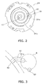
FIG 2 is a drawing of the stationary scroll ofFIG 1 as seen from below. -
FIG 3 is a drawing schematically showing the placement of the intermediate pressure groove formed in the stationary scroll ofFIG 1 . -
FIG 4 is a longitudinal cross-sectional view of the stationary scroll ofFIG 1 . -
FIG 5 is a graph showing the relationship between crank angle and discharge pressure. -
FIG 6 is a drawing schematically showing the placement of the intermediate pressure groove formed in the stationary scroll according to a modification of the present invention. -
FIG 7 is a drawing schematically showing the placement of the intermediate pressure groove formed in the stationary scroll according to another modification of the present invention. - Next, an embodiment of the scroll compressor of the present invention is described with reference to the drawings.
- A scroll compressor 1 shown in
FIG. 1 is a high-low pressure dome-type scroll compressor and constitutes a refrigerant circuit together with an evaporator and/or a condenser, an expansion mechanism, and other components. The scroll compressor 1 fulfills the role of compressing a gas refrigerant in the refrigerant circuit, and the scroll compressor 1 is configured primarily from a long cylindrical hermetic dome-type casing 10, ascroll compressor mechanism 15, an Oldham ring 39, adrive motor 16, a lowermain bearing 60, anintake tube 19, and adischarge tube 20. Each of the configurational components of this scroll compressor 1 is described below in detail. - The
casing 10 has a substantially cylindricalcore casing part 11, a bowl-shapedtop wall part 12 hermetically welded to the upper end of thecore casing part 11, and a bowl-shapedbottom wall part 13 hermetically welded to the lower end part of thecore casing part 11. Accommodated in thecasing 10 are, primarily, thescroll compressor mechanism 15 for compressing a gas refrigerant, and thedrive motor 16 disposed below thescroll compressor mechanism 15. Thescroll compressor mechanism 15 and thedrive motor 16 are connected by adrive shaft 17 disposed so as to extend vertically within thecasing 10. As a result, agap space 18 is formed between thescroll compressor mechanism 15 and thedrive motor 16. - The
scroll compressor mechanism 15 is configured primarily from ahousing 23, astationary scroll 24 disposed as being secured in place above thehousing 23, and amovable scroll 26 which meshes with thestationary scroll 24, as shown inFIG 1 . - Each of the configurational components of the
scroll compressor mechanism 15 is described below in detail. - The
stationary scroll 24 is configured primarily from a flat plate-shaped panel 24a, and a spiral (involute)lap 24b formed on the lower surface of thepanel 24a, as shown inFIG 1 . - In the
panel 24a, adischarge port 41 communicating with acompression chamber 40, described hereinafter, is formed through the approximate center of thepanel 24a. Thedischarge port 41 is formed so as to extend vertically in the center portion of thepanel 24a. The shape of the opening surface of thedischarge port 41 is not circular because the opening surface area is increased to reduce discharge pressure drop. A counterbore space 141 (seeFIG. 4 ) communicating with thedischarge port 41 is formed in the top surface of thepanel 24a. Thesymbol 80 inFIG 4 indicates a discharge valve, which is a non-return valve for opening and closing thecounterbore space 141. - Furthermore, an enlarged concave part 42 (see
FIG. 1 ) communicating with thedischarge port 41 and thecounterbore space 141 is formed in the top surface of thepanel 24a. The enlargedconcave part 42 is configured from a concave part which is recessed into the top surface of thepanel 24a and which widens horizontally. Alid member 44 is fastened in place to the top surface of thestationary scroll 24 by abolt 44a so as to close up the enlargedconcave part 42. Formed in the enlargedconcave part 42 is amuffler space 45 composed of an expansion chamber which reduces the operating noises of thescroll compressor mechanism 15 due to being covered up by thelid member 44. Thestationary scroll 24 and thelid member 44 are sealed by being stuck together with a packing (not shown). - The
movable scroll 26 is configured primarily from apanel 26a, a spiral (involute)lap 26b formed on the top surface of thepanel 26a, a bearingpart 26c formed on the lower surface of thepanel 26a, and agroove part 26d formed in both ends of thepanel 26a, as shown inFIG 1 . - The
movable scroll 26 is an outer drive movable scroll. Specifically, themovable scroll 26 has thebearing part 26c which fits with the outer side of thedrive shaft 17. - The
movable scroll 26 is supported on thehousing 23 by the Oldham ring 39 being fitted into thegroove part 26d. The upper end of thedrive shaft 17 is fittably inserted into the bearingpart 26c. Due to being assembled in thescroll compressor mechanism 15 in this manner, themovable scroll 26 revolves within thehousing 23 without being spun by the rotation of thedrive shaft 17. Thelap 26b of themovable scroll 26 is meshed with thelap 24b of thestationary scroll 24, and thecompression chamber 40 is formed between the connecting parts of the twolaps compression chamber 40, as themovable scroll 26 revolves, the volume between the twolaps - A
back pressure chamber 63 is formed in thepanel 26a of themovable scroll 26, on the side that is opposite the side where thelap 26b is formed, as shown inFIGS. 1 to 3 . Theback pressure chamber 63 is a space enclosed by a housingconcave part 31 recessed into the center of the top surface of thehousing 23, thepanel 26a of themovable scroll 26, and the Oldham ring 39. - An
intermediate pressure groove 61 that can communicate with thecompression chamber 40 is formed in the surface of thepanel 24a of thestationary scroll 24 in the side where thelap 26b is formed. - In the
panel 26a of themovable scroll 26, a through-hole 62 capable of intermittently causing theintermediate pressure groove 61 to communicate with theback pressure chamber 63 is formed through the thickness direction of thepanel 26a of themovable scroll 26. The through-hole 62 ofFIG 3 is a round hole. - The turning motion of the
movable scroll 26 causes the through-hole 62 in themovable scroll 26 to move along a circular rotation trajectory R relative to theintermediate pressure groove 61 in thestationary scroll 24, as shown inFIG 3 . Consequently, when the through-hole 62 overlaps theintermediate pressure groove 61, intermediate pressure can be led into theback pressure chamber 63. - Thus, since the
intermediate pressure groove 61 communicating with thecompression chamber 40 is formed in thepanel 24a of thestationary scroll 24, and the through-hole 62 allowing theintermediate pressure groove 61 to communicate with theback pressure chamber 63 is formed in thepanel 26a of themovable scroll 26, theintermediate pressure groove 61 and the through-hole 62 can be smaller than a conventional connecting passage for leading in intermediate pressure. As a result, the desired intermediate pressure can be efficiently led into theback pressure chamber 63, pulsation is suppressed, and intermediate pressure conformance can be improved. - Pulsation is a phenomenon whereby discharge pressure P rises locally within a predetermined crank angle θ range, as can be seen from the relationship between crank angle θ (degrees) and discharge pressure P (kgf/mm2), as shown in
FIG 5 . - The
intermediate pressure groove 61 has a shape wherein adistal end part 61 a bends so as to extend in a direction of intersecting with the rotation trajectory R in which the through-hole 62 moves along with the revolving of themovable scroll 26, as shown inFIGS. 2 and 3 . - Particularly, the
distal end part 61a of theintermediate pressure groove 61 extends in a direction orthogonal to the rotation trajectory R in which the through-hole 62 moves along with the revolving of themovable scroll 26. - The
intermediate pressure groove 61 herein has a shape in which thedistal end part 61a bends so as to be orthogonal to the rotation trajectory R, but theintermediate pressure groove 61 can also be formed into a linear shape, or theintermediate pressure groove 61 can be lengthened. - The
intermediate pressure groove 61 is formed in the space one circumference inward from the outermost side of thelap 24b of thestationary scroll 24, as shown inFIG 2 . - The
housing 23 is press-fitted and fixed in place in thecore casing part 11 through the entire circumferential direction of its external peripheral surface. In other words, thecore casing part 11 and thehousing 23 are hermetically sealed together through their entire circumferences. Therefore, the interior of thecasing 10 is divided into a high-pressure space 28 below thehousing 23 and a low-pressure space 29 above thehousing 23. Thestationary scroll 24 is fixed by a bolt or the like to thehousing 23 so that the upper end surface of the housing is sealed to the lower end surface of thestationary scroll 24. Also formed in thehousing 23 are the housingconcave part 31 recessed into the center of the top surface, and a bearingpart 32 protruding downward from the center of the lower surface. A bearinghole 33 is formed vertically through the bearingpart 32, and thedrive shaft 17 is rotatably fitted into the bearinghole 33 via abearing 34. - A connecting
passage 46 is formed in thescroll compressor mechanism 15, extending through thestationary scroll 24 and thehousing 23. The connectingpassage 46 is formed so that thestationary scroll 24 communicates with a housing-side passage 48 formed as a notch in thehousing 23. The upper end of the connectingpassage 46 opens into the enlargedconcave part 42, and the lower end of the connectingpassage 46, i.e., the lower end of the housing-side passage 48, opens into the lower end surface of thehousing 23. In other words, adischarge port 49 which allows the refrigerant in the connectingpassage 46 to flow out to thegap space 18 is configured from the lower end opening of the housing-side passage 48. - The Oldham ring 39 is a member for preventing spinning movement of the
movable scroll 26 as described above, and is fitted into Oldham grooves (not shown) formed in thehousing 23. These Oldham grooves are elliptical grooves and are set in positions that face each other in thehousing 23. - The
drive motor 16 is a DC motor in the present embodiment, and is configured primarily from anannular stator 51 fixed to the inner wall surface of thecasing 10, and arotor 52 rotatably accommodated so that a slight gap (an air gap passage) is present relative to the inner side of thestator 51. Thedrive motor 16 is disposed so that the upper end of acoil end 53 formed in the top side of thestator 51 is positioned at approximately the same height as the lower end of the bearingpart 32 of thehousing 23. - A copper wire is wound around the teeth of the
stator 51, and thecoil end 53 is formed above and below. The external peripheral surface of thestator 51 is provided with core-cut parts formed as notches in a plurality of locations from the upper end surface to the lower end surface of thestator 51, at predetermined intervals in the circumferential direction. Amotor cooling passage 55, which extends vertically between thecore casing part 11 and thestator 51, is formed by these core-cut parts. - The
rotor 52 is driveably connected to themovable scroll 26 of thescroll compressor mechanism 15 via thedrive shaft 17, which is disposed in the axial center of thecore casing part 11 so as to extend vertically. Aguide plate 58 for guiding refrigerant flowing out of thedischarge port 49 of the connectingpassage 46 into themotor cooling passage 55 is set in thegap space 18. - The lower
main bearing 60 is set in a lower space below thedrive motor 16. This lowermain bearing 60, which is fixed to thecore casing part 11, constitutes a lower-end bearing of thedrive shaft 17 and supports thedrive shaft 17. - The
intake tube 19 is for leading the refrigerant of the refrigerant circuit to thescroll compressor mechanism 15, and is hermetically fitted into thetop wall part 12 of thecasing 10. Theintake tube 19 passes vertically through the low-pressure space 29, and an inner end part thereof is fitted into thestationary scroll 24. - The
discharge tube 20 is for discharging the refrigerant in thecasing 10 out of thecasing 10, and is hermetically fitted into thecore casing part 11 of thecasing 10. Thedischarge tube 20 opens in a position protruding downward to the center from the inside surface of the core body, and thedischarge tube 20 communicates with thegap space 18, which is the high-pressure space 28. - Next, the movement action of the scroll compressor 1 is described in a simple manner while referring to
FIG 1 . First, when thedrive motor 16 is driven, thedrive shaft 17 rotates, and themovable scroll 26 performs a revolving movement without spinning. A low-pressure gas refrigerant is then drawn into thecompression chamber 40 from the peripheral edge of thecompression chamber 40 through theintake tube 19, and the refrigerant is compressed as the capacity of thecompression chamber 40 changes, forming a high-pressure gas refrigerant. This high-pressure gas refrigerant is discharged from the center of thecompression chamber 40, through thedischarge port 41 and thecounterbore space 141, into themuffler space 45. - Additionally, while the
movable scroll 26 is undergoing the turning movement, when the through-hole 62 passing through thepanel 26a of themovable scroll 26 in the thickness direction communicates with theintermediate pressure groove 61 formed in thepanel 24a of thestationary scroll 24, thecompression chamber 40 communicates with theback pressure chamber 63 on the lower side of themovable scroll 26 via theintermediate pressure groove 61 and the through-hole 62. The desired intermediate pressure can thereby be efficiently led into theback pressure chamber 63, pulsation is suppressed, and intermediate pressure conformance can be improved. - The refrigerant then flows out to the
gap space 18 through the connectingpassage 46, the housing-side passage 48, and thedischarge port 49, and flows downward between theguide plate 58 and the inner surface of thecore casing part 11. When this gas refrigerant flows downward between theguide plate 58 and the inner surface of thecore casing part 11, some is diverted to flow circumferentially between theguide plate 58 and thedrive motor 16, and the lubrication oil mixed in the gas refrigerant is separated from the refrigerant. The rest of the diverted gas refrigerant flows downward through themotor cooling passage 55 until it reaches a motor lower space, after which it reverses and flows upward through the air gap passage between thestator 51 and therotor 52 or themotor cooling passage 55 on the side (the left side inFIG 1 ) facing the connectingpassage 46. The gas refrigerant that has passed through theguide plate 58 and the gas refrigerant that has flowed through the air gap passage or themotor cooling passage 55 are then mixed together in thegap space 18 and discharged from thedischarge tube 20 out of thecasing 10. After circulating through the refrigerant circuit, the gas refrigerant discharged out of thecasing 10 is drawn back through theintake tube 19 into thescroll compressor mechanism 15, where it is compressed. - In the scroll compressor 1 of the embodiment, the turning movement of the
movable scroll 26 causes the through-hole 62 in themovable scroll 26 to move along a circular rotation trajectory R relative to theintermediate pressure groove 61 in thestationary scroll 24, as shown inFIG 3 . Consequently, intermediate pressure can be led in when the through-hole 62 overlaps theintermediate pressure groove 61, and intermediate pressure cannot be led in when there is no overlap. - Thus, since the
intermediate pressure groove 61 communicating with thecompression chamber 40 is formed in thepanel 24a of thestationary scroll 24, and the through-hole 62 communicating theintermediate pressure groove 61 with theback pressure chamber 63 is formed in thepanel 26a of themovable scroll 26, theintermediate pressure groove 61 and the through-hole 62 can be smaller than a conventional connecting passage for leading in intermediate pressure. As a result, the desired intermediate pressure can be efficiently led into theback pressure chamber 63, pulsation is suppressed, and intermediate pressure conformance can be improved. - Moreover, the
intermediate pressure groove 61 of thestationary scroll 24 and the through-hole 62 of themovable scroll 26 can be formed smaller in width, and the pulsation per rotation in the turning of themovable scroll 26 can thereby be reduced. - The shape and surface area of the passageway whereby the
intermediate pressure groove 61 and the through-hole 62 communicate with each rotation of themovable scroll 26 are appropriately varied, oil (the cause of mixing loss) that has accumulated in theback pressure chamber 63 and other intermediate pressure spaces (intermediate pressure chambers) can thereby be efficiently carried to thecompression chamber 40, and oil can be ensured for the seal in thecompression chamber 40. - As described above, by providing both the
intermediate pressure groove 61 which is formed in thepanel 24a of thestationary scroll 24 and communicates with thecompression chamber 40, and the through-hole 62 which is formed in thepanel 26a of themovable scroll 26 and which causes theintermediate pressure groove 61 to communicate with theback pressure chamber 63, the intermediate pressure obtained during compression inside thecompression chamber 40 can be led into theback pressure chamber 63 at a pinpoint. As a result, pulsation can be suppressed and stable intermediate pressure can be led in. - Moreover, since the volume led in per rotation is small, dead volume can be reduced.
- Furthermore, since the
intermediate pressure groove 61 communicating with thecompression chamber 40 is formed in the surface of thepanel 24a of thestationary scroll 24, theintermediate pressure groove 61 is easily machined. The through-hole 62 communicating theintermediate pressure groove 61 and theback pressure chamber 63 can be formed easily due to passing through thepanel 26a of themovable scroll 26 in the thickness direction. - In the scroll compressor 1 of the embodiment, since the
intermediate pressure groove 61 extends in a direction that intersects the rotation trajectory R through which the through-hole 62 moves along with the revolving of themovable scroll 26 as shown inFIGS. 2 and 3 , theintermediate pressure groove 61 and the through-hole 62 can reliably communicate at a pinpoint. The desired intermediate pressure can thereby be led into theback pressure chamber 63, pulsation can be suppressed, and stable intermediate pressure can be led in. - In the scroll compressor 1 of the embodiment, since the
distal end part 61 a of theintermediate pressure groove 61 extends in a direction orthogonal to the rotation trajectory R through which the through-hole 62 moves along with the revolving of themovable scroll 26, theintermediate pressure groove 61 and the through-hole 62 can reliably be in communication with each other in the shortest amount of time. The desired intermediate pressure can thereby be led into theback pressure chamber 63, pulsation can be suppressed, and stable intermediate pressure can be led in. Moreover, the volume led in per rotation can be reduced to a minimum, and dead volume can be reduced to a minimum. - Furthermore, in the scroll compressor 1 of the embodiment, since the
intermediate pressure groove 61 is formed in the space one circumference inward from the outermost side of thelap 24b of thestationary scroll 24 as shown inFIG 2 , there is little thrust loss, an intermediate pressure at which themovable scroll 26 does not turn over can be reliably obtained, and theintermediate pressure groove 61 can be reliably formed in a position where it will not interfere with other components. - The present invention is not limited to the example of the scroll compressor 1 of the above embodiment, wherein the through-hole 62 (see
FIG 3 ) having a circular cross section is formed in thepanel 26a of themovable scroll 26, and through-holes of various other shapes may be used; e.g., a through-hole 62 having an elliptical cross section may be used as shown inFIG 6 . In this case, pulsation can be suppressed, and intermediate pressure conformance can be improved. - In particular, intermediate pressure conformance can be further improved without increasing the communication time duration by making the shape of the through-
hole 62 for leading in intermediate pressure into an oblong hole. - As another modification, there may be a plurality of through-
holes 62 as shown inFIG 7 . Two or more through-holes 62 are disposed so that they can be allowed to communicate simultaneously with theintermediate pressure groove 61. Pulsation can be suppressed and intermediate pressure conformance can be improved in this case as well. - Moreover, intermediate pressure conformance can be further improved without increasing the communication time duration by providing a plurality of through-
holes 62. - A plurality of oblong holes such as the one of Modification (A) above may also be formed.
- The degree of freedom in the position where the through-
hole 62 is formed may also be increased and the restrictions on the position where the intermediate pressure is led in may be reduced by flattening the scroll shapes of thestationary scroll 24 and themovable scroll 26 and increasing their diameters. - The present invention can be applied in various forms to a scroll compressor for intermittently leading intermediate pressure into the back pressure chamber of a movable scroll.
-
- (Patent Literature 1) Japanese Patent Registration No.
2707517
Claims (6)
- A scroll compressor (1) comprising a stationary scroll (24) and a movable scroll (26), each of which scrolls having a helical lap (24b, 26b) provided to one surface of individual panels (24a, 26a); wherein
the lap (24b) of the stationary scroll (24) and the lap (26b) of the movable scroll (26) are brought together, whereby a compression chamber (40) is formed between the adjacent lap (24b) of the stationary scroll (24) and the lap (26b) of the movable scroll (26);
a back pressure chamber (63) is formed in the side of the panel (26a) of the movable scroll (26) that is opposite of the side where the lap (26b) is formed;
at least one concave part (61) capable of communicating with the compression chamber (40) is formed in the surface of the panel (24a) of the stationary scroll (24) on the side where the lap (24b) is formed; and
at least one through-hole (62) capable of intermittently causing the concave part (61) and the back pressure chamber (63) to communicate is formed in the panel (26a) of the movable scroll (26), the through-hole (62) being formed through a thickness direction of the panel (26a) of the movable scroll (26). - The scroll compressor (1) according to claim 1, wherein
the concave part (61) is a groove extending in a direction that intersects a trajectory over which the through-hole (62) moves along with the revolving of the movable scroll (26). - The scroll compressor (1) according to claim 2, wherein
the groove extends in a direction orthogonal to the trajectory over which the through-hole (62) moves along with the revolving of the movable scroll (26). - The scroll compressor (1) according to any of claims 1 through 3, wherein
the through-hole (62) has a cross section in the shape of an oblong hole. - The scroll compressor (1) according to any of claims 1 through 4, wherein
a plurality of the through-holes (62) are formed; and
two or more through-holes (62) can communicate simultaneously with the concave part (61). - The scroll compressor (1) according to any of claims 1 through 5, wherein
the concave part (61) is formed in a space one circumference inward from an outermost side of the lap (24b) of the stationary scroll (24).
Applications Claiming Priority (2)
| Application Number | Priority Date | Filing Date | Title |
|---|---|---|---|
| JP2009217799A JP4992948B2 (en) | 2009-09-18 | 2009-09-18 | Scroll compressor |
| PCT/JP2010/065926 WO2011034082A1 (en) | 2009-09-18 | 2010-09-15 | Scroll compressor |
Publications (3)
| Publication Number | Publication Date |
|---|---|
| EP2479435A1 true EP2479435A1 (en) | 2012-07-25 |
| EP2479435A4 EP2479435A4 (en) | 2016-04-06 |
| EP2479435B1 EP2479435B1 (en) | 2018-08-01 |
Family
ID=43758683
Family Applications (1)
| Application Number | Title | Priority Date | Filing Date |
|---|---|---|---|
| EP10817195.0A Active EP2479435B1 (en) | 2009-09-18 | 2010-09-15 | Scroll compressor |
Country Status (7)
| Country | Link |
|---|---|
| US (1) | US8961158B2 (en) |
| EP (1) | EP2479435B1 (en) |
| JP (1) | JP4992948B2 (en) |
| KR (1) | KR20120054098A (en) |
| CN (1) | CN102549264B (en) |
| ES (1) | ES2693293T3 (en) |
| WO (1) | WO2011034082A1 (en) |
Cited By (3)
| Publication number | Priority date | Publication date | Assignee | Title |
|---|---|---|---|---|
| CN104685213A (en) * | 2012-09-27 | 2015-06-03 | 大金工业株式会社 | Scroll compressor |
| EP3404264A1 (en) * | 2017-05-19 | 2018-11-21 | OET GmbH | Spiral compressor and its operating method |
| US11448218B2 (en) | 2015-11-20 | 2022-09-20 | OET GmbH | Displacement machine according to the spiral principle, method to regulate pressure in the counter-pressure chamber by using a pressure difference and characteristic curve |
Families Citing this family (4)
| Publication number | Priority date | Publication date | Assignee | Title |
|---|---|---|---|---|
| JP5083401B2 (en) * | 2010-11-01 | 2012-11-28 | ダイキン工業株式会社 | Scroll compressor |
| JP7169737B2 (en) * | 2016-07-29 | 2022-11-11 | ダイキン工業株式会社 | scroll compressor |
| US11236648B2 (en) | 2018-11-20 | 2022-02-01 | Emerson Climate Technologies, Inc. | Climate-control system having oil cooling control system |
| US11566624B2 (en) | 2020-10-21 | 2023-01-31 | Emerson Climate Technologies, Inc. | Compressor having lubrication system |
Family Cites Families (10)
| Publication number | Priority date | Publication date | Assignee | Title |
|---|---|---|---|---|
| US4596521A (en) * | 1982-12-17 | 1986-06-24 | Hitachi, Ltd. | Scroll fluid apparatus |
| JPS59180094A (en) * | 1983-03-31 | 1984-10-12 | Toshiba Corp | Scroll type compressor |
| JP2707517B2 (en) | 1988-11-11 | 1998-01-28 | 株式会社日立製作所 | Scroll fluid machine |
| JPH04175483A (en) * | 1990-11-07 | 1992-06-23 | Hitachi Ltd | Scroll compressor |
| JP2002106482A (en) * | 2000-09-29 | 2002-04-10 | Toyota Industries Corp | Scroll type compressor and gas compression method |
| JP2007270697A (en) | 2006-03-31 | 2007-10-18 | Hitachi Ltd | Scroll fluid machinery |
| JP5061584B2 (en) * | 2006-11-15 | 2012-10-31 | パナソニック株式会社 | Scroll compressor |
| JP4471034B2 (en) * | 2008-07-15 | 2010-06-02 | ダイキン工業株式会社 | Scroll compressor |
| ES2564845T3 (en) * | 2010-11-08 | 2016-03-29 | Daikin Industries, Ltd. | Spiral compressor |
| KR101480472B1 (en) * | 2011-09-28 | 2015-01-09 | 엘지전자 주식회사 | Scroll compressor |
-
2009
- 2009-09-18 JP JP2009217799A patent/JP4992948B2/en active Active
-
2010
- 2010-09-15 EP EP10817195.0A patent/EP2479435B1/en active Active
- 2010-09-15 KR KR1020127009700A patent/KR20120054098A/en not_active Ceased
- 2010-09-15 WO PCT/JP2010/065926 patent/WO2011034082A1/en not_active Ceased
- 2010-09-15 US US13/395,767 patent/US8961158B2/en active Active
- 2010-09-15 CN CN201080041450.5A patent/CN102549264B/en active Active
- 2010-09-15 ES ES10817195.0T patent/ES2693293T3/en active Active
Non-Patent Citations (1)
| Title |
|---|
| See references of WO2011034082A1 * |
Cited By (5)
| Publication number | Priority date | Publication date | Assignee | Title |
|---|---|---|---|---|
| CN104685213A (en) * | 2012-09-27 | 2015-06-03 | 大金工业株式会社 | Scroll compressor |
| US9759216B2 (en) | 2012-09-27 | 2017-09-12 | Daikin Industries, Ltd. | Scroll compressor |
| US11448218B2 (en) | 2015-11-20 | 2022-09-20 | OET GmbH | Displacement machine according to the spiral principle, method to regulate pressure in the counter-pressure chamber by using a pressure difference and characteristic curve |
| EP3404264A1 (en) * | 2017-05-19 | 2018-11-21 | OET GmbH | Spiral compressor and its operating method |
| US11131306B2 (en) | 2017-05-19 | 2021-09-28 | OET GmbH | Displacement machine including only one displacement spiral passage and gas connection line in communication with a counter pressure chamber |
Also Published As
| Publication number | Publication date |
|---|---|
| US20120177521A1 (en) | 2012-07-12 |
| EP2479435A4 (en) | 2016-04-06 |
| CN102549264A (en) | 2012-07-04 |
| KR20120054098A (en) | 2012-05-29 |
| WO2011034082A1 (en) | 2011-03-24 |
| CN102549264B (en) | 2015-08-26 |
| JP2011064179A (en) | 2011-03-31 |
| ES2693293T3 (en) | 2018-12-10 |
| EP2479435B1 (en) | 2018-08-01 |
| US8961158B2 (en) | 2015-02-24 |
| JP4992948B2 (en) | 2012-08-08 |
Similar Documents
| Publication | Publication Date | Title |
|---|---|---|
| EP2479435B1 (en) | Scroll compressor | |
| US7753663B2 (en) | Mounting structure of discharge valve in rotary compressor | |
| US9163632B2 (en) | Injection port and orbiting-side wrap for a scroll compressor | |
| JP4008883B2 (en) | Hermetic rotary compressor muffler | |
| US20160108917A1 (en) | Scroll compressor | |
| AU2002224180A1 (en) | Muffler for hermetic rotary compressor | |
| JP2005264827A (en) | Scroll compressor | |
| JP2010285930A (en) | Scroll compressor | |
| JP2012219654A (en) | Rotary fluid machine | |
| EP1820970A1 (en) | Compressor | |
| KR101447039B1 (en) | Scroll compressor | |
| JP2007170253A (en) | Scroll compressor | |
| CN101429940B (en) | Compressor with muffler | |
| JP5195774B2 (en) | Scroll compressor | |
| EP2894341B1 (en) | Compressor | |
| JP2011017292A (en) | Scroll compressor | |
| WO2017141309A1 (en) | Rotary compressor | |
| JP2010065560A (en) | Scroll compressor | |
| JP2011017304A (en) | Scroll compressor | |
| JP2025513152A (en) | Compressor | |
| EP2325492A1 (en) | Scroll fluid machine | |
| CN120684400A (en) | Compressor and refrigeration system | |
| JP2017145883A (en) | Bearing housing and rotating machine | |
| KR20150098467A (en) | Scroll compressor |
Legal Events
| Date | Code | Title | Description |
|---|---|---|---|
| PUAI | Public reference made under article 153(3) epc to a published international application that has entered the european phase |
Free format text: ORIGINAL CODE: 0009012 |
|
| 17P | Request for examination filed |
Effective date: 20120321 |
|
| AK | Designated contracting states |
Kind code of ref document: A1 Designated state(s): AL AT BE BG CH CY CZ DE DK EE ES FI FR GB GR HR HU IE IS IT LI LT LU LV MC MK MT NL NO PL PT RO SE SI SK SM TR |
|
| DAX | Request for extension of the european patent (deleted) | ||
| RA4 | Supplementary search report drawn up and despatched (corrected) |
Effective date: 20160304 |
|
| RIC1 | Information provided on ipc code assigned before grant |
Ipc: F04C 18/02 20060101AFI20160229BHEP |
|
| GRAP | Despatch of communication of intention to grant a patent |
Free format text: ORIGINAL CODE: EPIDOSNIGR1 |
|
| STAA | Information on the status of an ep patent application or granted ep patent |
Free format text: STATUS: GRANT OF PATENT IS INTENDED |
|
| INTG | Intention to grant announced |
Effective date: 20180405 |
|
| GRAS | Grant fee paid |
Free format text: ORIGINAL CODE: EPIDOSNIGR3 |
|
| GRAA | (expected) grant |
Free format text: ORIGINAL CODE: 0009210 |
|
| STAA | Information on the status of an ep patent application or granted ep patent |
Free format text: STATUS: THE PATENT HAS BEEN GRANTED |
|
| AK | Designated contracting states |
Kind code of ref document: B1 Designated state(s): AL AT BE BG CH CY CZ DE DK EE ES FI FR GB GR HR HU IE IS IT LI LT LU LV MC MK MT NL NO PL PT RO SE SI SK SM TR |
|
| REG | Reference to a national code |
Ref country code: GB Ref legal event code: FG4D |
|
| REG | Reference to a national code |
Ref country code: CH Ref legal event code: EP Ref country code: AT Ref legal event code: REF Ref document number: 1024632 Country of ref document: AT Kind code of ref document: T Effective date: 20180815 |
|
| REG | Reference to a national code |
Ref country code: IE Ref legal event code: FG4D |
|
| REG | Reference to a national code |
Ref country code: DE Ref legal event code: R096 Ref document number: 602010052393 Country of ref document: DE |
|
| REG | Reference to a national code |
Ref country code: FR Ref legal event code: PLFP Year of fee payment: 9 |
|
| REG | Reference to a national code |
Ref country code: NL Ref legal event code: MP Effective date: 20180801 |
|
| REG | Reference to a national code |
Ref country code: ES Ref legal event code: FG2A Ref document number: 2693293 Country of ref document: ES Kind code of ref document: T3 Effective date: 20181210 |
|
| REG | Reference to a national code |
Ref country code: LT Ref legal event code: MG4D |
|
| REG | Reference to a national code |
Ref country code: AT Ref legal event code: MK05 Ref document number: 1024632 Country of ref document: AT Kind code of ref document: T Effective date: 20180801 |
|
| PG25 | Lapsed in a contracting state [announced via postgrant information from national office to epo] |
Ref country code: FI Free format text: LAPSE BECAUSE OF FAILURE TO SUBMIT A TRANSLATION OF THE DESCRIPTION OR TO PAY THE FEE WITHIN THE PRESCRIBED TIME-LIMIT Effective date: 20180801 Ref country code: LT Free format text: LAPSE BECAUSE OF FAILURE TO SUBMIT A TRANSLATION OF THE DESCRIPTION OR TO PAY THE FEE WITHIN THE PRESCRIBED TIME-LIMIT Effective date: 20180801 Ref country code: NL Free format text: LAPSE BECAUSE OF FAILURE TO SUBMIT A TRANSLATION OF THE DESCRIPTION OR TO PAY THE FEE WITHIN THE PRESCRIBED TIME-LIMIT Effective date: 20180801 Ref country code: BG Free format text: LAPSE BECAUSE OF FAILURE TO SUBMIT A TRANSLATION OF THE DESCRIPTION OR TO PAY THE FEE WITHIN THE PRESCRIBED TIME-LIMIT Effective date: 20181101 Ref country code: GR Free format text: LAPSE BECAUSE OF FAILURE TO SUBMIT A TRANSLATION OF THE DESCRIPTION OR TO PAY THE FEE WITHIN THE PRESCRIBED TIME-LIMIT Effective date: 20181102 Ref country code: NO Free format text: LAPSE BECAUSE OF FAILURE TO SUBMIT A TRANSLATION OF THE DESCRIPTION OR TO PAY THE FEE WITHIN THE PRESCRIBED TIME-LIMIT Effective date: 20181101 Ref country code: AT Free format text: LAPSE BECAUSE OF FAILURE TO SUBMIT A TRANSLATION OF THE DESCRIPTION OR TO PAY THE FEE WITHIN THE PRESCRIBED TIME-LIMIT Effective date: 20180801 Ref country code: IS Free format text: LAPSE BECAUSE OF FAILURE TO SUBMIT A TRANSLATION OF THE DESCRIPTION OR TO PAY THE FEE WITHIN THE PRESCRIBED TIME-LIMIT Effective date: 20181201 Ref country code: PL Free format text: LAPSE BECAUSE OF FAILURE TO SUBMIT A TRANSLATION OF THE DESCRIPTION OR TO PAY THE FEE WITHIN THE PRESCRIBED TIME-LIMIT Effective date: 20180801 Ref country code: SE Free format text: LAPSE BECAUSE OF FAILURE TO SUBMIT A TRANSLATION OF THE DESCRIPTION OR TO PAY THE FEE WITHIN THE PRESCRIBED TIME-LIMIT Effective date: 20180801 |
|
| PG25 | Lapsed in a contracting state [announced via postgrant information from national office to epo] |
Ref country code: AL Free format text: LAPSE BECAUSE OF FAILURE TO SUBMIT A TRANSLATION OF THE DESCRIPTION OR TO PAY THE FEE WITHIN THE PRESCRIBED TIME-LIMIT Effective date: 20180801 Ref country code: LV Free format text: LAPSE BECAUSE OF FAILURE TO SUBMIT A TRANSLATION OF THE DESCRIPTION OR TO PAY THE FEE WITHIN THE PRESCRIBED TIME-LIMIT Effective date: 20180801 Ref country code: HR Free format text: LAPSE BECAUSE OF FAILURE TO SUBMIT A TRANSLATION OF THE DESCRIPTION OR TO PAY THE FEE WITHIN THE PRESCRIBED TIME-LIMIT Effective date: 20180801 |
|
| PG25 | Lapsed in a contracting state [announced via postgrant information from national office to epo] |
Ref country code: MC Free format text: LAPSE BECAUSE OF FAILURE TO SUBMIT A TRANSLATION OF THE DESCRIPTION OR TO PAY THE FEE WITHIN THE PRESCRIBED TIME-LIMIT Effective date: 20180801 Ref country code: EE Free format text: LAPSE BECAUSE OF FAILURE TO SUBMIT A TRANSLATION OF THE DESCRIPTION OR TO PAY THE FEE WITHIN THE PRESCRIBED TIME-LIMIT Effective date: 20180801 Ref country code: CZ Free format text: LAPSE BECAUSE OF FAILURE TO SUBMIT A TRANSLATION OF THE DESCRIPTION OR TO PAY THE FEE WITHIN THE PRESCRIBED TIME-LIMIT Effective date: 20180801 Ref country code: RO Free format text: LAPSE BECAUSE OF FAILURE TO SUBMIT A TRANSLATION OF THE DESCRIPTION OR TO PAY THE FEE WITHIN THE PRESCRIBED TIME-LIMIT Effective date: 20180801 |
|
| REG | Reference to a national code |
Ref country code: CH Ref legal event code: PL |
|
| REG | Reference to a national code |
Ref country code: DE Ref legal event code: R097 Ref document number: 602010052393 Country of ref document: DE |
|
| PG25 | Lapsed in a contracting state [announced via postgrant information from national office to epo] |
Ref country code: DK Free format text: LAPSE BECAUSE OF FAILURE TO SUBMIT A TRANSLATION OF THE DESCRIPTION OR TO PAY THE FEE WITHIN THE PRESCRIBED TIME-LIMIT Effective date: 20180801 Ref country code: SM Free format text: LAPSE BECAUSE OF FAILURE TO SUBMIT A TRANSLATION OF THE DESCRIPTION OR TO PAY THE FEE WITHIN THE PRESCRIBED TIME-LIMIT Effective date: 20180801 Ref country code: SK Free format text: LAPSE BECAUSE OF FAILURE TO SUBMIT A TRANSLATION OF THE DESCRIPTION OR TO PAY THE FEE WITHIN THE PRESCRIBED TIME-LIMIT Effective date: 20180801 |
|
| PLBE | No opposition filed within time limit |
Free format text: ORIGINAL CODE: 0009261 |
|
| STAA | Information on the status of an ep patent application or granted ep patent |
Free format text: STATUS: NO OPPOSITION FILED WITHIN TIME LIMIT |
|
| REG | Reference to a national code |
Ref country code: BE Ref legal event code: MM Effective date: 20180930 |
|
| REG | Reference to a national code |
Ref country code: IE Ref legal event code: MM4A |
|
| PG25 | Lapsed in a contracting state [announced via postgrant information from national office to epo] |
Ref country code: LU Free format text: LAPSE BECAUSE OF NON-PAYMENT OF DUE FEES Effective date: 20180915 |
|
| 26N | No opposition filed |
Effective date: 20190503 |
|
| PG25 | Lapsed in a contracting state [announced via postgrant information from national office to epo] |
Ref country code: IE Free format text: LAPSE BECAUSE OF NON-PAYMENT OF DUE FEES Effective date: 20180915 |
|
| PG25 | Lapsed in a contracting state [announced via postgrant information from national office to epo] |
Ref country code: CH Free format text: LAPSE BECAUSE OF NON-PAYMENT OF DUE FEES Effective date: 20180930 Ref country code: BE Free format text: LAPSE BECAUSE OF NON-PAYMENT OF DUE FEES Effective date: 20180930 Ref country code: SI Free format text: LAPSE BECAUSE OF FAILURE TO SUBMIT A TRANSLATION OF THE DESCRIPTION OR TO PAY THE FEE WITHIN THE PRESCRIBED TIME-LIMIT Effective date: 20180801 Ref country code: LI Free format text: LAPSE BECAUSE OF NON-PAYMENT OF DUE FEES Effective date: 20180930 |
|
| PG25 | Lapsed in a contracting state [announced via postgrant information from national office to epo] |
Ref country code: MT Free format text: LAPSE BECAUSE OF NON-PAYMENT OF DUE FEES Effective date: 20180915 |
|
| PG25 | Lapsed in a contracting state [announced via postgrant information from national office to epo] |
Ref country code: TR Free format text: LAPSE BECAUSE OF FAILURE TO SUBMIT A TRANSLATION OF THE DESCRIPTION OR TO PAY THE FEE WITHIN THE PRESCRIBED TIME-LIMIT Effective date: 20180801 |
|
| PG25 | Lapsed in a contracting state [announced via postgrant information from national office to epo] |
Ref country code: PT Free format text: LAPSE BECAUSE OF FAILURE TO SUBMIT A TRANSLATION OF THE DESCRIPTION OR TO PAY THE FEE WITHIN THE PRESCRIBED TIME-LIMIT Effective date: 20180801 Ref country code: HU Free format text: LAPSE BECAUSE OF FAILURE TO SUBMIT A TRANSLATION OF THE DESCRIPTION OR TO PAY THE FEE WITHIN THE PRESCRIBED TIME-LIMIT; INVALID AB INITIO Effective date: 20100915 |
|
| PG25 | Lapsed in a contracting state [announced via postgrant information from national office to epo] |
Ref country code: CY Free format text: LAPSE BECAUSE OF FAILURE TO SUBMIT A TRANSLATION OF THE DESCRIPTION OR TO PAY THE FEE WITHIN THE PRESCRIBED TIME-LIMIT Effective date: 20180801 Ref country code: MK Free format text: LAPSE BECAUSE OF NON-PAYMENT OF DUE FEES Effective date: 20180801 |
|
| P01 | Opt-out of the competence of the unified patent court (upc) registered |
Effective date: 20230525 |
|
| PGFP | Annual fee paid to national office [announced via postgrant information from national office to epo] |
Ref country code: DE Payment date: 20250730 Year of fee payment: 16 |
|
| PGFP | Annual fee paid to national office [announced via postgrant information from national office to epo] |
Ref country code: IT Payment date: 20250825 Year of fee payment: 16 |
|
| PGFP | Annual fee paid to national office [announced via postgrant information from national office to epo] |
Ref country code: GB Payment date: 20250731 Year of fee payment: 16 |
|
| PGFP | Annual fee paid to national office [announced via postgrant information from national office to epo] |
Ref country code: FR Payment date: 20250808 Year of fee payment: 16 |
|
| PGFP | Annual fee paid to national office [announced via postgrant information from national office to epo] |
Ref country code: ES Payment date: 20251013 Year of fee payment: 16 |