EP2479367A2 - Schließvorrichtung einer automatischen Tür - Google Patents
Schließvorrichtung einer automatischen Tür Download PDFInfo
- Publication number
- EP2479367A2 EP2479367A2 EP12151816A EP12151816A EP2479367A2 EP 2479367 A2 EP2479367 A2 EP 2479367A2 EP 12151816 A EP12151816 A EP 12151816A EP 12151816 A EP12151816 A EP 12151816A EP 2479367 A2 EP2479367 A2 EP 2479367A2
- Authority
- EP
- European Patent Office
- Prior art keywords
- door
- auxiliary drive
- drive means
- closing
- cylinder
- Prior art date
- Legal status (The legal status is an assumption and is not a legal conclusion. Google has not performed a legal analysis and makes no representation as to the accuracy of the status listed.)
- Withdrawn
Links
- 230000006835 compression Effects 0.000 claims abstract description 26
- 238000007906 compression Methods 0.000 claims abstract description 26
- 238000006073 displacement reaction Methods 0.000 claims description 44
- 239000012190 activator Substances 0.000 claims description 24
- 230000004913 activation Effects 0.000 claims description 9
- 230000003213 activating effect Effects 0.000 claims description 7
- 230000000903 blocking effect Effects 0.000 description 9
- 239000002184 metal Substances 0.000 description 4
- 230000000284 resting effect Effects 0.000 description 4
- 230000008901 benefit Effects 0.000 description 2
- 238000010276 construction Methods 0.000 description 2
- 238000005265 energy consumption Methods 0.000 description 2
- 230000006872 improvement Effects 0.000 description 2
- 238000009434 installation Methods 0.000 description 2
- 230000001154 acute effect Effects 0.000 description 1
- 230000008859 change Effects 0.000 description 1
- 210000000038 chest Anatomy 0.000 description 1
- 230000009849 deactivation Effects 0.000 description 1
- 230000006837 decompression Effects 0.000 description 1
- 230000001419 dependent effect Effects 0.000 description 1
- 230000000694 effects Effects 0.000 description 1
- 238000012423 maintenance Methods 0.000 description 1
- 230000007257 malfunction Effects 0.000 description 1
- 230000002040 relaxant effect Effects 0.000 description 1
- 230000000717 retained effect Effects 0.000 description 1
- 239000013589 supplement Substances 0.000 description 1
Images
Classifications
-
- E—FIXED CONSTRUCTIONS
- E05—LOCKS; KEYS; WINDOW OR DOOR FITTINGS; SAFES
- E05D—HINGES OR SUSPENSION DEVICES FOR DOORS, WINDOWS OR WINGS
- E05D15/00—Suspension arrangements for wings
- E05D15/36—Suspension arrangements for wings moving along slide-ways so arranged that one guide-member of the wing moves in a direction substantially perpendicular to the movement of another guide member
- E05D15/38—Suspension arrangements for wings moving along slide-ways so arranged that one guide-member of the wing moves in a direction substantially perpendicular to the movement of another guide member for upwardly-moving wings, e.g. up-and-over doors
-
- E—FIXED CONSTRUCTIONS
- E05—LOCKS; KEYS; WINDOW OR DOOR FITTINGS; SAFES
- E05D—HINGES OR SUSPENSION DEVICES FOR DOORS, WINDOWS OR WINGS
- E05D13/00—Accessories for sliding or lifting wings, e.g. pulleys, safety catches
- E05D13/10—Counterbalance devices
- E05D13/14—Counterbalance devices with weights
- E05D13/145—Counterbalance devices with weights specially adapted for overhead wings
-
- E—FIXED CONSTRUCTIONS
- E05—LOCKS; KEYS; WINDOW OR DOOR FITTINGS; SAFES
- E05F—DEVICES FOR MOVING WINGS INTO OPEN OR CLOSED POSITION; CHECKS FOR WINGS; WING FITTINGS NOT OTHERWISE PROVIDED FOR, CONCERNED WITH THE FUNCTIONING OF THE WING
- E05F15/00—Power-operated mechanisms for wings
- E05F15/60—Power-operated mechanisms for wings using electrical actuators
- E05F15/603—Power-operated mechanisms for wings using electrical actuators using rotary electromotors
- E05F15/665—Power-operated mechanisms for wings using electrical actuators using rotary electromotors for vertically-sliding wings
- E05F15/668—Power-operated mechanisms for wings using electrical actuators using rotary electromotors for vertically-sliding wings for overhead wings
-
- E—FIXED CONSTRUCTIONS
- E05—LOCKS; KEYS; WINDOW OR DOOR FITTINGS; SAFES
- E05Y—INDEXING SCHEME ASSOCIATED WITH SUBCLASSES E05D AND E05F, RELATING TO CONSTRUCTION ELEMENTS, ELECTRIC CONTROL, POWER SUPPLY, POWER SIGNAL OR TRANSMISSION, USER INTERFACES, MOUNTING OR COUPLING, DETAILS, ACCESSORIES, AUXILIARY OPERATIONS NOT OTHERWISE PROVIDED FOR, APPLICATION THEREOF
- E05Y2201/00—Constructional elements; Accessories therefor
- E05Y2201/40—Motors; Magnets; Springs; Weights; Accessories therefor
- E05Y2201/404—Function thereof
- E05Y2201/41—Function thereof for closing
- E05Y2201/412—Function thereof for closing for the final closing movement
-
- E—FIXED CONSTRUCTIONS
- E05—LOCKS; KEYS; WINDOW OR DOOR FITTINGS; SAFES
- E05Y—INDEXING SCHEME ASSOCIATED WITH SUBCLASSES E05D AND E05F, RELATING TO CONSTRUCTION ELEMENTS, ELECTRIC CONTROL, POWER SUPPLY, POWER SIGNAL OR TRANSMISSION, USER INTERFACES, MOUNTING OR COUPLING, DETAILS, ACCESSORIES, AUXILIARY OPERATIONS NOT OTHERWISE PROVIDED FOR, APPLICATION THEREOF
- E05Y2201/00—Constructional elements; Accessories therefor
- E05Y2201/40—Motors; Magnets; Springs; Weights; Accessories therefor
- E05Y2201/47—Springs
-
- E—FIXED CONSTRUCTIONS
- E05—LOCKS; KEYS; WINDOW OR DOOR FITTINGS; SAFES
- E05Y—INDEXING SCHEME ASSOCIATED WITH SUBCLASSES E05D AND E05F, RELATING TO CONSTRUCTION ELEMENTS, ELECTRIC CONTROL, POWER SUPPLY, POWER SIGNAL OR TRANSMISSION, USER INTERFACES, MOUNTING OR COUPLING, DETAILS, ACCESSORIES, AUXILIARY OPERATIONS NOT OTHERWISE PROVIDED FOR, APPLICATION THEREOF
- E05Y2900/00—Application of doors, windows, wings or fittings thereof
- E05Y2900/10—Application of doors, windows, wings or fittings thereof for buildings or parts thereof
- E05Y2900/106—Application of doors, windows, wings or fittings thereof for buildings or parts thereof for garages
Definitions
- the invention relates to an automated door closing device. More particularly, the present invention relates to an automated door closure device, for example of the garage door type intended to switch from a vertical position to a horizontal position or vice versa to obstruct or not a passage and allowing a certified closure and blocked of said door.
- suction cup type systems Other known devices use suction cup type systems. These devices generally require the presence of a metal part on the door cooperating not with a mobile part of the frame but with an electromagnet applying a holding force on the door with the aid of said metal part of the door.
- this type of device ensures the closing of the door only when it is close enough to the electromagnet for the latter to produce a suction effect.
- This device also prevents the sound nuisance of the closure and generates a clacking sound when the metal part of the door contacts the electromagnet.
- This device also generates a significant energy consumption, requiring the operation of the electromagnet continuously.
- the security provided by such a device is questionable because any obstacle located between the metal part and the electromagnet prevents the proper operation of the system, and therefore the locking closure, easily providing access to possible thieves.
- Such door closure locking devices are in particular installed on overhead doors. These doors are for example for garages, private or public, and are usually automated to let the cars without requiring a driver to get off the vehicle to open and close the door. For its opening, the door switches from a vertical position to a horizontal position and generally parallel to a ceiling.
- the tilting of the door is generally obtained by sliding along lateral guide rails which are mounted on a door jamb. To facilitate the tilting and so that the door remains horizontal despite the weight of the door, it is used in a known manner a traction system connected to the door to counterbalance the weight of the door, for example a counterweight or a system of springs.
- the motors used are generally asynchronous DC motors or brushless motors (in English, brushless motor). These motors produce a driving force capable of tilting the door in one direction or the other, said force being applied to the lower part of the door.
- the device according to the invention aims to overcome the drawbacks of the closure systems of the prior art by providing an automated door device ensuring the closing of the door as well as its holding in closed position and its locking without generating nuisance noise or significant over-consumption of energy during its use.
- the invention aims to overcome this disadvantage in the context of a garage door swinging as described above and known per se. Furthermore, the device according to the invention has the advantage of using the drive force not used by the motor during a driving of the door for its own operation without requiring an increase in the power of said motor.
- the invention therefore relates to a closure device comprising a closing means of the door, swing, ventail or similar type a drive system being connected to said closing means and causing both closing and opening, a means auxiliary drive unit driving the closure means at the end of the race during its closing, characterized in that the auxiliary drive means is a compression / release operating system, the compression of the auxiliary drive means taking place at the end of the opening stroke of the closing means, the release of said auxiliary drive means causing the driving of said closing means to take place at the end of the closing stroke of said closing means.
- auxiliary drive means connected to the closing means, typically to the door, ensures the good closing of the door at the end of the race during its closing even in case of difficult weather conditions or malfunction or maladjustment of the door.
- main drive device the auxiliary drive means replacing or assisting the main drive means.
- the auxiliary drive means is movable, its displacement being linked to a displacement of the closing means, that is to say that the auxiliary drive means is mounted on a guiding device which may be the same guiding device as that of the door. The movement of the door then causes the displacement of the auxiliary drive means.
- the device according to the invention comprises a locking system in displacement of the auxiliary drive means.
- the displacement of the door being linked to the displacement of the means auxiliary drive, blocking it blocks the movement of the door.
- This locking system thus ensures the maintenance of the closed door because the auxiliary drive means is stopped in a fixed position. This locking of the door is ensured as the locking system of the auxiliary drive means is kept active.
- the auxiliary drive means is a compression / release operating system.
- compression / release system means a means that stores energy by compressing itself during a compression phase and releases this energy while developing during a release phase.
- the compression of the auxiliary drive means according to the invention is performed at the end of the opening stroke of the closure means.
- the release of the auxiliary drive means takes place at the end of closing stroke of said closing means.
- a main drive means in the form of a motor that develops the most force at the start of the race when opening the door.
- This important need at the beginning of the race when opening the door is mainly related to the weight of the door, the weight of the door being in the following movement opening gradually supported by the guide device.
- the engine At the end of the opening stroke, the engine has an important unused power reserve corresponding to the difference between the initial need in displacement and the current need. This power can be used to compress the auxiliary drive means without the need for a more powerful engine, nor generate significant overconsumption of the engine.
- the force stored by the auxiliary drive means is advantageously retained until its use at the end of the race in closing the door. This force is released and applied to the door at the end of the race to cause it to close.
- the auxiliary drive means does not require external power to the device advantageously using the force already available in the system.
- the auxiliary drive means comprises a compression / release activation system, preferably an automated activation system of said auxiliary drive means.
- This system cooperates with the auxiliary drive means to ensure that compression and relaxation are performed at the desired times. In activation, this system allows compression or relaxation of the auxiliary drive means. Without activation, the system blocks and does not allow compression or relaxation of the auxiliary drive means.
- the locking system constitutes a movable stop whose movement is perpendicular to the displacement of the auxiliary drive means. This stop is movable between a locking position limiting the displacement of the auxiliary drive means and a free position not limiting said displacement.
- the stop When releasing the auxiliary drive means, the stop serves as a fulcrum for said auxiliary drive means by blocking the displacement of its end bearing on said stop.
- the development of the auxiliary drive means therefore imposes the displacement of its end not bearing against the stop. Said end being connected to the door causes the closing movement of the door.
- This stop also guarantees the closing lock of the door by preventing its return in opening as the additional drive means abuts against it. A translation of the stop releases the movement of the auxiliary drive means, the latter can then move and no longer blocking the movement of the door opening.
- the stop of the locking system comprises a beveled non-return ratchet slidably mounted on an activator.
- the activator controls the movement of the pawl to position it on or off the path of the auxiliary drive means. In a rest position, the activator applies, for example by means of a spring or the like, a force on the pawl keeping it in the path of said auxiliary drive means.
- the displacement of the auxiliary drive means brings it into contact with the non-return pawl, more particularly the auxiliary drive means comes into contact with the beveled portion of said pawl.
- the driving means then applies in a direction forming an acute angle with said beveled portion, a force able to move the pawl which, translated perpendicular to the direction of movement of said auxiliary drive means, is moved out of the path of this last releasing his passage.
- the activator After passing the auxiliary drive means, the activator imposes a return to the rest position at the ratchet, a flat face of said ratchet being then vis-à-vis the auxiliary drive means and blocking its movement in the opposite direction.
- the abutment of the auxiliary drive means on the flat face of the pawl allows a fulcrum of the auxiliary drive means, this support imposing the development of the drive means by a displacement of its end connected to the door.
- the blocking of the auxiliary drive means in a direction in the opposite direction prevents the movement of the door opening.
- Such opening of the door is possible only when the pawl activator slides the latter so as to release the path of the auxiliary drive means, releasing at the same time the door opening.
- the auxiliary drive means comprises a jack, said jack comprising a push rod and a guide tube, an end of said jack being anchored to the closure means.
- This type of jack is known in many uses, for example in the field of office chairs, in the trap systems for buses or for some container or furniture.
- These cylinders comprise a mechanical system of the spring type or gas spring allowing, when activated, to move the push rod located in the tube to compress gas or a spring in one direction or on the contrary to release the compressed gas or this spring in the other direction.
- Such a cylinder develops over a greater or lesser length.
- An end of such a jack is according to the invention anchored to the door.
- the auxiliary drive means is held in abutment by the locking system, the release of the cylinder, corresponding to the output of the push rod of the tube, thus causes the displacement of the end of the cylinder anchored on the door and thus the movement of the door.
- the device according to the invention comprises an abutment limiting the displacement of the auxiliary drive means at the end of the race in opening of the door, a loading cam cooperating with said auxiliary drive means when the latter is in contact with said stop, said cam activating the auxiliary drive means.
- the movement of the cylinder is limited by a stop at the end of the race opening the door.
- This stop serves as a fulcrum to the cylinder.
- the activation cam activates the jack so that the rod of the latter can be moved in the tube, thus allowing its compression.
- the contact of the cylinder on the stop corresponds to the contact of the cam on the activator of the jack, that is to say that when the cylinder comes into contact with the stop, the cylinder is activated by the cam.
- the complete opening of the door causes a withdrawal of the cam releasing the activator by any means known to those skilled in the art, for example by a thrust of a shoulder of the door on the cam causing its withdrawal from the the activator.
- the cam can also be elastic, the application of a minimum pressure being necessary for the activation of the jack.
- the drive speed of the opening door can be greater than the maximum speed of movement of the rod in the cylinder tube, and the difference in speed requires a displacement of the cylinder despite the presence of the cam on the activator.
- the removal of the load cam or the speed difference between the door opening and the maximum speed of movement of the rod in the tube ensures that the cylinder is driven in movement by the door while it is in compression.
- the device according to the invention comprises a drive cam cooperating with the auxiliary drive means, this cooperation activating the auxiliary drive means at the end of the closing stroke of the closing means.
- the drive cam allows the release of the auxiliary drive means. This release causes a deployment of the auxiliary drive means driving the door at the end of the closing race.
- the cylinder After the cylinder has passed the locking device during the closing stroke of the door, it is driven by the door to contact with a drive cam.
- This drive cam activates the cylinder, thus allowing the release of said cylinder, moving the push rod in the tube.
- the locking system serving as a fulcrum of the cylinder only the end of the cylinder connected to the door can move, causing the door and thus ensuring its closure.
- the cam it is possible to provide for the cam to be retractable once the jack is fully released, in a manner similar to that described above for the load cam, or that it has a system for limiting the release of the cylinder.
- a system for limiting the release of the jack is for example useful in the context of a main drive of the door comprising a safety device detecting any obstacles and stopping the closing of the door in case of encounter with an obstacle.
- the position of the cam is such that it only activates the jack when it has passed the blocking system by a certain distance.
- the jack when the jack cooperates with the cam, the jack develops in the direction of the locking system and moves the activator on the cylinder towards said locking system thereby deactivating said jack.
- the cylinder is no longer activated, only the movement of the door can bring the contact between the cylinder and the drive cam. If the door encounters an obstacle and remains blocked, the actuator can not force the door to close despite the obstacle.
- the invention is subsequently presented in the context of a tilting garage door guided in tilting by vertical and horizontal guide rails.
- This description is in no way limiting and the invention relates to any secure closure system comprising a door, leaf, leaf or the like associated with a drive means and comprising an auxiliary drive means driving the door at the end of the race. closing.
- the qualifiers "superior”, “lower”, “high” and “low” of an element of the device are used as part of a normal installation of the device, that is to say relative in the context of a garage door installed on a flat horizontal floor and such that in the closed position the door is substantially vertical.
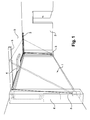
- the figure 1 is a schematic perspective view of a garage door of the prior art.
- the device according to the invention is intended to drive at least partially in displacement, for example by tilting, a closure element 1 such as a door 1, in the example shown a garage door 1 integrated in a construction structure 2 , for example the walls of a garage.
- a closure element 1 such as a door 1
- a construction structure 2 for example the walls of a garage.
- Such a door 1 authorizes or blocks access to the garage by sliding by sliding along a guide device 3, generally horizontal and vertical guide rails 3, located on either side of the door 1 integrated in the building structure 2 and cooperating with the door 1 in a manner known to those skilled in the art.
- a driving force is applied to the door 1 by means of a drive means 4, for example to 4.
- This force tilts the door 1 from its closed vertical position to a horizontal open position, generally parallel to a ceiling 5 of the garage.
- This tilting is guided by the guiding device 3.
- a counterweight system 6, or a spring system or any other adaptable system by the skilled person. It is obvious, and easily adaptable by those skilled in the art, to apply this driving force for the opening, closing, or any other movement of a door, by tilting, side sliding or other.
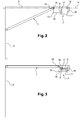
- the figure 2 represents a schematic cross-sectional view of a secure closure device according to the invention at the end of the opening stroke.
- the closure device comprises an auxiliary drive means 7.
- This auxiliary drive means is intended to drive the door 1 at the end of the closing stroke.
- this auxiliary drive means 7 drives the door 1 only during its closing end position.
- This auxiliary drive means 7 may be of any type, for example in the form of an auxiliary engine, a cylinder or other.
- the door 1 is connected to the auxiliary drive means 7.
- the auxiliary drive means 7 is movable, its displacement being linked to the displacement of the door 1.
- the device according to the invention comprises a locking system 8 of the displacement of the means 7. Typically, if the auxiliary drive means 7 is locked in motion, the door 1 can not be moved.
- the associated drive means 7 is a compression / release drive means.
- This type of drive means can be compressed by undergoing for example the application of a force, this force compressing said auxiliary drive means 7 which stores it until released. The force is subsequently released, releasing the force stored during compression.
- this type of drive means 7 comprises an activator 9. Such an activator 9 allows or blocks the compression and / or release of the auxiliary drive means 7 depending on whether it is activated or not.
- the motor 4 applies on a lower part of the door a driving force on the door 1 to ensure its tilting.
- the most important need for power for the drive of the door 1 takes place at the beginning of the opening stroke of the door because the drive requires lifting the door 1, the door 1 being substantially vertical and not resting. on the horizontal guide rails 3.
- the opening stroke of the door 1 requires a motor power 4 degressive, the door 1 at the end of the opening stroke resting mainly on the horizontal guide rails 3, a minimum force to ensure complete opening being sufficient.
- the driving force required to close the door 1 is degressive and relatively low compared to that required for its opening, the door 1 resting integrally on the guide rails 3 at the beginning of closing stroke and the weight of said door 1 helping to ensure its closing end of stroke closing.
- the engine 4 is therefore generally calibrated according to the driving force required at the start of the opening stroke, that is to say requiring the greatest power from the engine 4.
- the invention ingeniously provides for compressing the auxiliary drive means 7 without imposing a need to change the calibration of the engine 4.
- the compression of the auxiliary drive means 7 is preferably performed at the end of the opening stroke. It is not necessary to increase the power or to recalibrate the motor 4 in order to compress the auxiliary drive means 7, the latter being compressed using the motor 4 at the end of the opening stroke, that is to say at a time of the displacement of the door 1 where the motor 4 uses only a small part of its power.
- the release of the auxiliary drive means 7 is used to drive the end of the closing stroke the door 1 as described below.
- the auxiliary drive means 7 is a cylinder 7.
- This type of compression / release cylinder is known in the field of height-adjustable office chairs, vehicle openings such as doors or chests etc. ... such a cylinder 7 may be gas or spring.
- the jack 7 comprises a push rod 10 slidably mounted in a guide tube 11. In compression, the push rod 10 is inserted at most in the tube 11, a gas or a spring, depending on the type of cylinder 7, is compressed in the tube 11. Inversely, while relaxing, the rod 10 is mainly located at outside the tube 11, the gas or the spring is decompressed, this decompression pushing the rod 10 mainly out of the tube 11. Thus the cylinder 7 develops more or less depending on whether it is compressed or released.
- the activator 9 allows or not the displacement of the rod 10 in the tube 11.
- the rod 10 is locked in a fixed position in the tube 11 and the cylinder 7 can not not develop.
- an end 12 of the jack 7 is secured to the upper part 13 of the door 1.
- the jack 7 is integral in displacement of the door 1 and is therefore slidably mounted along a sliding axis 14 parallel to the rail of 3.
- the cylinder 7 is slidably mounted in the horizontal guide rail 3 of the door 1, the horizontal guide rail 3 being slightly longer than a conventional guide rail.
- the jack 7 cooperates with the horizontal guide rail 3 and is mounted on rollers 15 cooperating with said guide rail 3 in a manner easily adaptable by those skilled in the art.
- the compression of the cylinder 7 end of stroke associated with the positioning of said cylinder 7 on the horizontal guide rail 3 of the door 1 also has a significant advantage in terms of energy consumption. Indeed, the force of the motor 4 being applied in the lower part of the door 1 and the distance to travel to reach the full open position of the door for the upper part 13 of the door 1 being much less than the distance still to for the lower part of the door, the compression of the cylinder 7 requires an insignificant supplement of driving force of the engine 4 compared to the force that is necessary to drive the lower part of the door to its full open position .
- the guide rail 3 comprises an abutment 16.
- This abutment 16 limits the displacement of the cylinder 7 at the end of the stroke when opening the door 1, that is to say that the cylinder 7 linked in displacement to the door 1 comes to contact bearing on the abutment 16.
- a loading cam 17 cooperates with the activator 9 of the cylinder 7.
- this loading cam 17 is of elastic type, the simple contact between the loading cam 17 and the activator 9 is not sufficient to activate the cylinder 7.
- the displacement of the door 1 at the end of closing stroke imposes a force on the cylinder 7 which bears on the stop 16.
- the cylinder 7 retransmits this force on the loading cam 17 which allows the activation of said cylinder 7 allowing its compression.
- the jack 7 being activated, the movement of the door 1 at the end of the closing stroke then compresses the jack 7, the push rod 10 then sliding in the tube 11.
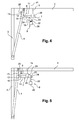
- the figure 3 represents a schematic cross-sectional view of a device according to the invention in full opening of the door
- the jack 7 In full opening of the door 1, the jack 7 is compressed, the push rod 10 is inserted into the tube 10 at most.
- the loading cam 17 is retractable, such a cam 17 activating the jack 7 as soon as the jack 7 comes into contact with the stop 16 until the door 1 is fully open.
- the door 1 may for example have a shoulder 18 coming, in full opening of the door 1, move or cause displacement of the load cam 17, said cam 17 then activating the cylinder 7 and the latter then remaining compressed.
- the figure 4 represents a partial schematic cross-sectional view of a closing device during closure.
- the locking system 8 can have a stop 19 in the form of a beveled antiturn ratchet.
- This non-return pawl 19 is slidably mounted on an activator 20.
- the pawl 19 is movable along an axis of displacement 21 perpendicular to the displacement of the jack 7, typically vertical.
- the pawl 19 is held by a pressure means 22 of the activator in its high position, said pressure means 22 applying a holding force on said pawl 19.
- This pressure means 22 is of any known type for example in the form of a spring 22 or other. In this high position, the pawl 19 is located on a trajectory of the jack 7.
- the jack 7 When driving the jack 7 through the closing gate 1, the jack 7 is brought into contact with the pawl 19. More particularly, during the closing stroke of the gate 1, the jack 7 is brought into contact with a bevelled face 23 of the pawl 19. The displacement of the cylinder 7 applies a force on the beveled face 23 of the pawl 19 opposing the pressure means 23 of the activator 20. The support in displacement of the cylinder 7 on the beveled face 23 then imposes a displacement of the pawl 19 in a low position in which the pawl 19 does not block the displacement of the jack 7.
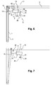
- the figure 5 represents a schematic cross-sectional view of a device according to the invention at the end of the closing stroke
- the jack 7 At the end of the closing stroke of the door 1, the jack 7 has exceeded in its stroke the pawl 19 of the locking device 8 and therefore no longer exerts any force on said pawl 19. The pawl is thus held in its upper position by the pressure means 22.
- the jack 7 is him vis-à-vis a face 24 of the pawl 19 flat and perpendicular to its axis of displacement.
- the jack 7 cooperates with a driving cam 25.
- This driving cam 25 may be of the same type as the loading cam 17.
- the driving cam 25 activates the jack 7 which, in the absence of force compressing it, relaxes.
- the release of the cylinder 7 results in a sliding of the push rod 10 in the tube 11 and thus the development of said cylinder 7.
- the cylinder 7, activated by the drive cam 25, continues to develop.
- the pawl 19, and more particularly the face 24 of said pawl 19, then blocks the development of the jack 7 towards said pawl 19 and serves as a support for the force released by the jack 7 during its development is applied to the door 1 , imposing and causing the closing movement thereof.
- the figure 6 represents a schematic cross sectional view of a device according to the invention in complete closure of the door.
- the jack 7 In complete closing of the door 1, the jack 7 is preferably completely released and has driven the door 1 to its position of complete closure. The cylinder 7 is then fully developed and the push rod 10 is located mainly outside the tube 11. The cylinder 7 is in abutment against the flat face 24 of the pawl 19 by one of its ends 26 and the other end 13 is linked to the door in fully closed position.
- the cylinder 7 is preferably deactivated.
- the drive cam 25 can be made elastic, that is to say that a maximum development of the cylinder 7 does not provide sufficient pressure on the drive cam 25 to maintain the activation of the cylinder 7
- the cam 25 can also be made retractable, a shoulder 27 of the door 1 activating the removal of the cam and thus deactivating the cylinder 7 in a manner easily adaptable by those skilled in the art.
- the deactivation of the cam 25 blocks the jack 7 in the developed position. An attempt to open the door is then blocked by the cylinder 7 abuts on the face 24 of the pawl 19. Only a withdrawal of the pawl 19 out of the path of the cylinder 7 can then release the door 1.
- the device according to the The invention thus secures the opening of the door 1, the latter being able to open only if the withdrawal order of the pawl 19 is given to the activator 20.
- the figure 7 represents a schematic cross sectional view of a device according to the invention at the beginning of the opening stroke.
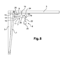
- the figure 8 represents a schematic perspective view of an alternative embodiment of a device according to the invention.
- the drive cam 25 is positioned to allow a short stroke of the cylinder 7 between the pawl 19 and the drive cam 25.
- This embodiment is provided so that the cylinder 7 does not drive. the door 1 moving only if the door is not blocked by an obstacle.
- the jack 7 is driven in displacement by the door 1 to the contact of the drive cam 25 which activates said jack 7.
- the free stroke between the jack 7 and the pawl 19 allows the development of the jack 7 in the direction of said 19 ratchet, this development breaking contact between the cylinder 7 and the drive cam 25.
- the cylinder 7 is then disabled again and can be reactivated and continue to develop if the door 1 continues to move.
- the cylinder 7 is in any case a secure locking system of the door 1 being blocked in abutment against the pawl 19 until said pawl 19 has not received a corresponding order.
- the end 13 of the jack 7 connected to the door 1 is preferably the push rod 10, the activator 9 of the jack 7 being located on the tube 11 and having to move towards the pawl 19 to deactivate said jack 7.
- auxiliary drive means 7 located on either side of the door on the horizontal guide rails 3.
- the cylinder 7 according to the invention can be also linked to the door 1 whether by the push rod 10 or by the tube 11.
Landscapes
- Engineering & Computer Science (AREA)
- Mechanical Engineering (AREA)
- Power-Operated Mechanisms For Wings (AREA)
- Air-Flow Control Members (AREA)
Applications Claiming Priority (1)
| Application Number | Priority Date | Filing Date | Title |
|---|---|---|---|
| FR1150456A FR2970726B1 (fr) | 2011-01-20 | 2011-01-20 | Dispositif de fermeture de porte automatise |
Publications (2)
| Publication Number | Publication Date |
|---|---|
| EP2479367A2 true EP2479367A2 (de) | 2012-07-25 |
| EP2479367A3 EP2479367A3 (de) | 2015-04-22 |
Family
ID=44510022
Family Applications (1)
| Application Number | Title | Priority Date | Filing Date |
|---|---|---|---|
| EP20120151816 Withdrawn EP2479367A3 (de) | 2011-01-20 | 2012-01-19 | Schließvorrichtung einer automatischen Tür |
Country Status (2)
| Country | Link |
|---|---|
| EP (1) | EP2479367A3 (de) |
| FR (1) | FR2970726B1 (de) |
Cited By (1)
| Publication number | Priority date | Publication date | Assignee | Title |
|---|---|---|---|---|
| CN112392356A (zh) * | 2020-11-18 | 2021-02-23 | 上海探见智能家居有限公司 | 一种智能门窗行程自动校准的方法 |
Family Cites Families (4)
| Publication number | Priority date | Publication date | Assignee | Title |
|---|---|---|---|---|
| DE8715917U1 (de) * | 1987-12-02 | 1988-04-28 | Müller, Günter, 5418 Goddert | Schwingtor, insbesondere für Garagen |
| GB2221951B (en) * | 1988-07-14 | 1992-04-15 | Jack Metcalf | Power operated garage door opener |
| US5371970A (en) * | 1993-03-08 | 1994-12-13 | Ganikon; Mark | Garage door locking apparatus |
| FR2734860B1 (fr) * | 1995-05-30 | 1997-07-25 | Trendel Et Fils A | Porte de garage basculante motorisee, disposant d'un compensateur de force variable |
-
2011
- 2011-01-20 FR FR1150456A patent/FR2970726B1/fr not_active Expired - Fee Related
-
2012
- 2012-01-19 EP EP20120151816 patent/EP2479367A3/de not_active Withdrawn
Non-Patent Citations (1)
| Title |
|---|
| None |
Cited By (2)
| Publication number | Priority date | Publication date | Assignee | Title |
|---|---|---|---|---|
| CN112392356A (zh) * | 2020-11-18 | 2021-02-23 | 上海探见智能家居有限公司 | 一种智能门窗行程自动校准的方法 |
| CN112392356B (zh) * | 2020-11-18 | 2022-06-10 | 上海探见智能家居有限公司 | 一种智能门窗行程自动校准的方法 |
Also Published As
| Publication number | Publication date |
|---|---|
| EP2479367A3 (de) | 2015-04-22 |
| FR2970726B1 (fr) | 2013-11-29 |
| FR2970726A1 (fr) | 2012-07-27 |
Similar Documents
| Publication | Publication Date | Title |
|---|---|---|
| FR2969200A1 (fr) | Procede d'actionnement d'un ensemble de battant d'un vehicule automobile | |
| EP0978609A1 (de) | Türschloss mit elektrischem Hilfsmotor | |
| LU81579A1 (fr) | Appareil de manoeuvre d'une porte et procede de commande de cet appareil | |
| FR2586744A1 (fr) | Serrure a ouverture et fermeture electriques, notamment pour portieres de vehicules automobiles | |
| EP0953094A1 (de) | Einsteckschloss | |
| EP2479367A2 (de) | Schließvorrichtung einer automatischen Tür | |
| EP0292361B1 (de) | Elektrisch betätigbares Schloss | |
| FR2860261A1 (fr) | Dispositif de fermeture d'une ouverture et vehicule automobile correspondant | |
| FR2937990A1 (fr) | Dispositif de serrure automatique | |
| EP0619408A1 (de) | Automatische Verriegelungsvorrichtung für eine Tür, insbesondere eine Schwingtür | |
| WO2019106310A1 (fr) | Systeme de verrouillage d'un vantail de porte paliere | |
| FR2709720A1 (fr) | Dispositif de secours pour commander électriquement depuis l'extérieur le déverrouillage d'une porte. | |
| FR2946684A1 (fr) | Ensemble de porte de garage. | |
| EP3473792B1 (de) | Vorrichtung zum hydraulischen verschliessen einer schliessvorrichtung mit elektrischer öffnung, und mit einer solchen vorrichtung ausgestattete schliessvorrichtung | |
| EP0903275A1 (de) | Motorbetriebene Verriegelungsvorrichtung eines Türflügels, Tür mit solch einer Vorrichtung und damit ausgerüstetes Schienenfahrzeug | |
| CA2576397C (fr) | Ensemble de mobilier urbain | |
| EP0477068B1 (de) | Entlüftungsvorrichtung für Gebäudefassaden | |
| EP4035745B1 (de) | Vorrichtung zur betätigung eines verschlusspaneels mit ausrückbarem anschlagmechanismus | |
| EP2246505A1 (de) | Schloss mit einem verschiebbaren Riegel, verschliessbar mit einem Kniehebel | |
| EP1943176B1 (de) | Gesicherte einrichtung für einen aufzug | |
| EP2578778A1 (de) | Feststellvorrichtung eines Öffnungselements eines Bauelements, das über Hilfsmittel zum Verriegeln und Entriegeln des Öffnungselements verfügt | |
| FR2990981A1 (fr) | Dispositif d'assistance a l'ouverture d'une porte battante | |
| EP2660414B1 (de) | Sicherheitsschleusenvorrichtung | |
| FR2923250A1 (fr) | Systeme de verrouillage d'un systeme d'ouverture/fermeture comprenant un element de verrouillage pivotant sur un panneau mobile du systeme d'ouverture/fermeture | |
| FR3081483A1 (fr) | Ensemble de serrure automatique |
Legal Events
| Date | Code | Title | Description |
|---|---|---|---|
| PUAI | Public reference made under article 153(3) epc to a published international application that has entered the european phase |
Free format text: ORIGINAL CODE: 0009012 |
|
| AK | Designated contracting states |
Kind code of ref document: A2 Designated state(s): AL AT BE BG CH CY CZ DE DK EE ES FI FR GB GR HR HU IE IS IT LI LT LU LV MC MK MT NL NO PL PT RO RS SE SI SK SM TR |
|
| AX | Request for extension of the european patent |
Extension state: BA ME |
|
| PUAL | Search report despatched |
Free format text: ORIGINAL CODE: 0009013 |
|
| AK | Designated contracting states |
Kind code of ref document: A3 Designated state(s): AL AT BE BG CH CY CZ DE DK EE ES FI FR GB GR HR HU IE IS IT LI LT LU LV MC MK MT NL NO PL PT RO RS SE SI SK SM TR |
|
| AX | Request for extension of the european patent |
Extension state: BA ME |
|
| RIC1 | Information provided on ipc code assigned before grant |
Ipc: E05F 15/16 00000000AFI20150313BHEP Ipc: E05D 15/38 20060101ALI20150313BHEP |
|
| 17P | Request for examination filed |
Effective date: 20150909 |
|
| RBV | Designated contracting states (corrected) |
Designated state(s): AL AT BE BG CH CY CZ DE DK EE ES FI FR GB GR HR HU IE IS IT LI LT LU LV MC MK MT NL NO PL PT RO RS SE SI SK SM TR |
|
| STAA | Information on the status of an ep patent application or granted ep patent |
Free format text: STATUS: THE APPLICATION IS DEEMED TO BE WITHDRAWN |
|
| 18D | Application deemed to be withdrawn |
Effective date: 20160802 |