EP2479366A2 - Schliessvorrichtung einer Öffnung eines Kraftfahrzeugs - Google Patents
Schliessvorrichtung einer Öffnung eines Kraftfahrzeugs Download PDFInfo
- Publication number
- EP2479366A2 EP2479366A2 EP12151804A EP12151804A EP2479366A2 EP 2479366 A2 EP2479366 A2 EP 2479366A2 EP 12151804 A EP12151804 A EP 12151804A EP 12151804 A EP12151804 A EP 12151804A EP 2479366 A2 EP2479366 A2 EP 2479366A2
- Authority
- EP
- European Patent Office
- Prior art keywords
- sliding
- panel
- shutter device
- rail
- movable panel
- Prior art date
- Legal status (The legal status is an assumption and is not a legal conclusion. Google has not performed a legal analysis and makes no representation as to the accuracy of the status listed.)
- Granted
Links
- 230000009471 action Effects 0.000 claims description 7
- 239000011888 foil Substances 0.000 claims description 2
- 238000006073 displacement reaction Methods 0.000 abstract description 9
- 238000000034 method Methods 0.000 description 18
- 230000006872 improvement Effects 0.000 description 4
- 238000007789 sealing Methods 0.000 description 3
- 241000920340 Pion Species 0.000 description 2
- 238000004026 adhesive bonding Methods 0.000 description 1
- 238000012550 audit Methods 0.000 description 1
- 230000000903 blocking effect Effects 0.000 description 1
- 230000037237 body shape Effects 0.000 description 1
- 230000008859 change Effects 0.000 description 1
- 238000007599 discharging Methods 0.000 description 1
- 239000011521 glass Substances 0.000 description 1
- 239000000463 material Substances 0.000 description 1
- 230000001681 protective effect Effects 0.000 description 1
- 230000001360 synchronised effect Effects 0.000 description 1
- 239000012780 transparent material Substances 0.000 description 1
- XLYOFNOQVPJJNP-UHFFFAOYSA-N water Substances O XLYOFNOQVPJJNP-UHFFFAOYSA-N 0.000 description 1
Images


Classifications
-
- E—FIXED CONSTRUCTIONS
- E05—LOCKS; KEYS; WINDOW OR DOOR FITTINGS; SAFES
- E05D—HINGES OR SUSPENSION DEVICES FOR DOORS, WINDOWS OR WINGS
- E05D15/00—Suspension arrangements for wings
- E05D15/06—Suspension arrangements for wings for wings sliding horizontally more or less in their own plane
- E05D15/10—Suspension arrangements for wings for wings sliding horizontally more or less in their own plane movable out of one plane into a second parallel plane
-
- B—PERFORMING OPERATIONS; TRANSPORTING
- B60—VEHICLES IN GENERAL
- B60J—WINDOWS, WINDSCREENS, NON-FIXED ROOFS, DOORS, OR SIMILAR DEVICES FOR VEHICLES; REMOVABLE EXTERNAL PROTECTIVE COVERINGS SPECIALLY ADAPTED FOR VEHICLES
- B60J1/00—Windows; Windscreens; Accessories therefor
- B60J1/08—Windows; Windscreens; Accessories therefor arranged at vehicle sides
- B60J1/12—Windows; Windscreens; Accessories therefor arranged at vehicle sides adjustable
- B60J1/16—Windows; Windscreens; Accessories therefor arranged at vehicle sides adjustable slidable
-
- E—FIXED CONSTRUCTIONS
- E05—LOCKS; KEYS; WINDOW OR DOOR FITTINGS; SAFES
- E05D—HINGES OR SUSPENSION DEVICES FOR DOORS, WINDOWS OR WINGS
- E05D15/00—Suspension arrangements for wings
- E05D15/06—Suspension arrangements for wings for wings sliding horizontally more or less in their own plane
- E05D15/10—Suspension arrangements for wings for wings sliding horizontally more or less in their own plane movable out of one plane into a second parallel plane
- E05D2015/1028—Suspension arrangements for wings for wings sliding horizontally more or less in their own plane movable out of one plane into a second parallel plane with only the wing moving transversely
- E05D2015/1039—Suspension arrangements for wings for wings sliding horizontally more or less in their own plane movable out of one plane into a second parallel plane with only the wing moving transversely the wing sliding transversely on the carriage
-
- E—FIXED CONSTRUCTIONS
- E05—LOCKS; KEYS; WINDOW OR DOOR FITTINGS; SAFES
- E05Y—INDEXING SCHEME ASSOCIATED WITH SUBCLASSES E05D AND E05F, RELATING TO CONSTRUCTION ELEMENTS, ELECTRIC CONTROL, POWER SUPPLY, POWER SIGNAL OR TRANSMISSION, USER INTERFACES, MOUNTING OR COUPLING, DETAILS, ACCESSORIES, AUXILIARY OPERATIONS NOT OTHERWISE PROVIDED FOR, APPLICATION THEREOF
- E05Y2900/00—Application of doors, windows, wings or fittings thereof
- E05Y2900/50—Application of doors, windows, wings or fittings thereof for vehicles
- E05Y2900/53—Type of wing
- E05Y2900/55—Windows
Definitions
- the field of the invention is that of racks defined in a wall and / or a frame of a structure, especially motor vehicles. More specifically, the invention relates to shutter devices of an array formed in a structural element, for example in the body of a vehicle, including the roof or a side wall, or in a door of the vehicle, and comprising a fixed part and a moving part relative to this fixed part, slidably, and capable of releasing or closing an opening by providing a flush appearance, seen from the outside.
- shutter devices of an array formed in a structural element, for example in the body of a vehicle, including the roof or a side wall, or in a door of the vehicle, and comprising a fixed part and a moving part relative to this fixed part, slidably, and capable of releasing or closing an opening by providing a flush appearance, seen from the outside.
- Such devices developed for several years by the holder of the present application, are in particular known by the term "flush bay".
- a report window maintained by a connecting frame.
- the latter may have an inner portion and an outer portion, which simultaneously pinch the edges of the ice and the opening in the body, with a seal.
- the frame can be glued to the edges of the bodywork.
- the most common technique for opening and closing a door window is to make it movable vertically in its own plane, by making it enter or leave the box or the door trim.
- Sliding panels are also known horizontally along rails formed in a frame.
- the shutter device (hereinafter referred to as "flush bay") presented in these documents comprises a fixed structure and a portion, or sliding panel, movable relative to this fixed assembly.
- the movable part is connected to the fixed assembly by functional elements which provide the required mobility and which are reported on the face of the fixed part facing the interior of the vehicle.
- Such a flush bay can be mounted completely independently of the vehicle, and reported from the outside, in the housing defined for this purpose on the vehicle body. It can also be secured, in particular by bonding to the lower part of a door, according to the technique described in the patent document.
- EP-1 022 172 This solves most of the sealing problems identified above. The same approach can also be used to make pavilions, including glazed pavilions with an opening.
- the flush bay presents, from the outside, a smooth, flush appearance, because no frame is needed on the contour of the opening formed in the fixed assembly.
- a guiding device comprising a first and a second guide rail fixedly mounted on the fixed assembly (or fixed structure) of the bay, both sides of the opening closed by the movable panel. It is mounted on the rails, to slide for example in a longitudinal direction, in a sliding plane between one (or more) open position and an intermediate release position in which it is facing. fixed panel and cleared from it.
- the invention relates more particularly to this second sealing technique, its variants and its improvements.
- the Holder has indeed proposed an improvement in guiding and locking such "flush bays", described in particular in the document PCT / EP2008 / 067264 , incorporated by reference in the present description.
- the flush bay comprises a fixed structure in which is defined an opening, and at least one sliding panel, having a frame carrying at least one guiding pin (generally two pins in the upper part and two pins in the lower part).
- Two sliders, or shuttles, secured to the pins are provided, and assembled so as to allow relative movement of the sliders relative to a corresponding guide element, along the sliding axis of the sliding panel, so as to allow movement of said panel sliding in a direction perpendicular to the plane of said fixed structure.
- the sliding panel is secured directly to an element of guiding and at least one slide, through the guiding pins, guided in a rail of simple shape, substantially rectilinear, to ensure its mobility in the direction of the sliding axis or perpendicular to the plan of the fixed structure.
- plan must be understood here in a broader sense: the plan formed by the bay is sometimes curved, according to one or two directions (this also justifies, in some cases, the term “substantially” used in the description and claims).
- This device therefore makes it possible to rest the sliding panel on an enlarged surface of the rail, by means of the sliding element and the slide and to implement rails of reduced thickness corresponding substantially to the thickness of the slide or the sliding element and / or the thickness intended for bonding the rail to the fixed structure.
- the space requirement of the shuttles may be problematic, and for example prevent or make complex the implementation of other functions requiring, for example, the passage of a cable in the rail. .
- the invention therefore particularly aims to overcome the disadvantages of the prior art mentioned above.
- one object of the invention is to provide a new technique for guiding a movable panel of a shutter bay of a structure, such as a motor vehicle or the like, enabling the passage of a position shutter, flush with the fixed panel to a sliding position, which is simple, effective and reliable.
- the invention also has the objective, at least for some of the embodiments, of providing such a technique, making it possible to easily implement other functions in a rail, or using a rail, without increasing the bulk. of it, especially in the width of the vehicle (direction in Y).
- Another object of the invention is to provide such a technique, to ensure an automatic locking (that is to say without additional specific action) of the mobile panel, when the it is returned to its closed position.
- each of said rails carries at least one movable shuttle sliding in said rail, along a sliding axis, and carrying at least one first fixed pin, said first fixed pin cooperating with a control groove for the passage of said position.
- shutter at said sliding position, and reciprocally, carried by a support integral with a frame of said movable panel, the device comprising at least one actuating element acting on one of said first pins, so as to move it in the control groove with which it cooperates.
- this actuating element can be manual, via a handle, or motorized, for example by means of a control cable.
- the actuating element By acting directly on one of the first pins, the actuating element makes it possible to modify the position of the movable panel in a particularly simple manner, and without it being necessary to integrate into the rail actuating devices that can act on the shuttle. It is thus possible to achieve a simpler rail, and smaller dimension.
- the shuttle, movable in the rail is particularly simple, and is a monobloc whole (that is to say without moving element relative to another) movable in one direction, and whose size can be very small, especially in width.
- the action of said actuating element on said first pin allows the passage in said sliding position of said movable panel, when the latter is in said closed position.
- This actuating element thus allows the easy passage of a locking position, in which the movable panel can not be slidably driven to a position in which the user, or a drive system, can drive this panel directly. sliding mobile.
- said actuating element cooperates with at least one return means, tending to return said movable panel in said closed position.
- Said return means may in particular be mounted between an abutment integral with a frame of said movable panel and said actuating element.
- said groove has at least a first portion extending transversely, allowing the passage of said closed position to said sliding position, and reciprocally, and a second locking portion extending substantially parallel to said sliding axis.
- the inclination of the first portion is advantageously of the order of 45 ° relative to the axis of sliding, but other more or less closed angles are possible.
- two supports can be provided, in each rail, so as to ensure an effective connection between the mobile panel and the shuttles.
- said shuttle carries two corresponding first pions.
- These first two pins may in particular be carried by a rod or a bar guided in the rail.
- the small size of this rod or of this bar, relative to the rail, allows a significant gain of space in the rail, allowing its use if necessary for other functions.
- At least one of the supports carries a second pin, adapted to cooperate with a corresponding keeper formed in said rail, in said closed position.
- the shutter device may comprise synchronization means, connecting the two shuttles equipping respectively the two rails, so that both shuttles are operated simultaneously.
- These synchronization means may for example comprise a cable or a foil.
- the device may form a glazed flag or a portion of a glazed flag.
- it can be mounted on a door or a side portion of the body.
- the invention also relates to motor vehicles comprising at least one closure device as described above.
- This device may in particular be mounted on a side wall of the vehicle or a door, or form all or part of a roof.
- vehicle automobile means here in a broad sense, and includes including trucks, vans, cars, campers, ...
- closure device can also be adapted to other structures with similar constraints, such as caravans, mobile homes, boats ...
- the invention therefore proposes a new approach for guiding a movable panel for a closure device intended for a motor vehicle (or a structure having similar characteristics, with regard to the bays, such as caravans, mobile homes , the boats, ...) and in particular for the device known under the term "flush bay", distributed in particular by the Holder of the present application.
- a shuttle is slidably guided in a rail provided for this purpose, parallel to a sliding axis defined by this rail.
- this shuttle moves in a single direction (typically along an axis parallel to the axis X, that is to say the axis corresponding to the length of the vehicle).
- This shuttle carries at least one, and in particular two, in the illustrated embodiment, pins, which also move only along the axis of sliding.
- the mobile panel carries, meanwhile, two grooves (which may be depending on the case lights or grooves, for example), provided to cooperate with each of the pins of the shuttle to control the closing and opening of the movable panel , that is to say its displacement in a direction perpendicular to the axis of sliding (typically the Y axis of the vehicle, corresponding to its width, or the Z axis, corresponding to the height, in the case of flags).
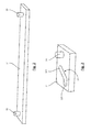
- FIGS. 1A and 1B illustrate, in a perspective view, an embodiment of such a manual opening flush bay, intended to close a bay formed in a side wall of the body of a vehicle.
- a flush bay may be provided in the structure of a caravan or a camper for example.
- This closure device therefore comprises a fixed part 11, generally of transparent material, also called fixed assembly or fixed panel, in which is pierced an opening 12.
- the opening may not be formed in the fixed panel, which then extends next to the opening (and the movable panel, in the closed position).
- the sliding panel comprises a window 131 provided with a frame 132, which can be guided along two substantially parallel rails 14 and 15, mounted on the inner face of the fixed panel 11 respectively in the lower part and in the upper part.
- these rails may also be non-parallel.
- the fixed part 11 can be made in several parts, here in two parts, a first part 111 defining the outline of the bay, generally in a material at least partially opaque or screen-printed, and having a shape adapted to the needs, for example substantially trapezoidal , or rectangular, and a part 112, transparent and fixed, inscribed in a second opening defined in the first part.
- the Figures 1A and 1B illustrate the bay seen from inside the vehicle.
- On this surface of the fixed portion 11 facing inward are mounted, for example by gluing, the two guide and holding rails 14 and 15 of the panel 13 movable in sliding relative to the fixed portion 11.
- the upper rail 15 and the lower rail 14 may if necessary not be parallel, to substantially follow the contours of the fixed part 11 (themselves generally imposed by the body shape of the vehicle).
- the lower rail 14 may in particular be equipped with means for recovering and discharging the water.
- the upper rail 15 may be covered with a protective and holding strip, for example of the type described in the document FR-0857313 .
- the figure 2 schematically illustrates a shuttle according to the approach of the invention. It is intended to move in the lower rail 14.
- a similar shuttle, preferably synchronized, is generally provided in the upper rail.
- This shuttle is essentially formed of a bar 21 carrying two fixed pins 22 and 23 with respect to this bar 21.
- the section of the bar 21 is adapted to slide in a corresponding slide of the rail.
- This section can be arbitrary, as long as it allows effective sliding and guiding. It may also be a rod, and more generally all forms of preferably relatively small width, relative to the width of the rail, to leave therein a free place for other functions (eg allowing the passage of a cable).
- the figure 3 illustrates one of the two supports 31 secured to the mobile frame 132 (where appropriate formed therein) and provided to cooperate with the pins 22 and 23, to control the displacement of the moving panel in sway, between the position of shutter and the sliding position, and vice versa.
- a groove 32 is formed in the support, in which the pin 22 can move.
- these supports are integrated directly into the frame of the movable panel, and the grooves are formed in this frame.
- This groove comprises an end portion 321, extending parallel to the axis of sliding (axis defined by the bar 21), and corresponds to the closed position. It also comprises an inclined portion 322 forming, with respect to this sliding axis, an angle of the order of 45 °.
- This portion 322 makes it possible to control the change of position of the movable panel. Other angles, and the case slightly different shapes, for example curved, may be envisaged.
- this groove may be through, or a groove formed in the support 31.
- This support also carries a locking pin 33, to ensure the locking of the movable panel in its closed position, as explained later.
- Two supports as illustrated on the figure 3 are provided to cooperate respectively with each of the pins 22 and 23 of the shuttle shown in FIG. figure 2 . However, preferably, only one of these parts carries a locking pin 33.
- the width of the supports 31A, 31B is substantially equal to the width of the rail 41 (such width being necessary for controlling the movement of the movable panel parallel to the sliding axis, but that the bar 21 is of substantially less width , leaving space available in the rail, behind this bar.
- An actuating element 43 is mounted on the mobile panel, movably relative to the frame of this movable panel, to allow control of the opening and closing thereof (manually or motorized, according to the case). This actuating element 43 is thus movable in a direction parallel to the sliding axis (arrow 44).
- a return means 45 here in the form of a helical spring, is placed between the actuating element 43 and a stop 46 fixed with respect to the frame of the movable panel.
- This spring makes it possible to ensure an automatic locking (that is to say without specific locking operation other than the action of bringing the movable panel back into the closed position).
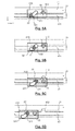
- FIGS. 5A to 5D illustrate different positions of the support 31 A relative to the pin 22 and the rail 41. These Figures are shown schematically, in a top view.
- the pin 22 (more generally the bar 21, and therefore the shuttle) is movable in a slideway 411, formed in the rail 41.
- the displacement of this pin 22, and therefore the shuttle moves only in the direction X.
- This provides a simple system to implement, and reliable over time.
- the support 31 A and therefore the mobile frame to which it is connected, move in turn in both directions X and Y.
- the Figure 5A presents the shutter position, in which the movable panel is in the plane of the fixed panel (see Figure 1A ).
- the pin 22 of the shuttle is in the end portion 321 of the groove, and the counter lock 33, which is secured to the support 31A is housed in a keeper 412 formed on the rail 41.
- the support 31 A is thus immobilized, in the direction X.
- the actuating element 43 cooperating with the spring 45, on maintaining this locked position, in the absence of a specific maneuver (manual or motorized).
- This maneuver can, for example be provided via it may be a spring button or a door handle.
- a cable 47 integrated in the frame of the movable panel, can be used to transmit the unlocking action to the other shuttle.
- This actuation can be direct, via a handle or a gripping element secured to this actuating element, or provided by a remote gripping element, for example according to the variants described in the patent application PCT / EP2008 / 067264 , already mentioned.
- This movement can also be motorized, for example via a geared motor, controlling the movement of the two actuating elements of each of the rails.
- the support 31 A is shown in a position corresponding to a partial opening (substantially one third of the opening movement).
- the actuating element 43 has moved the pin 23 into the groove 32 B (see figure 4 ).
- the pin 22 has moved in the same way, and is therefore in the transverse portion 322 of the groove.
- the support 31A, and therefore the movable panel has moved in the Y direction, and the locking pin 33 has begun to disengage from the striker 412.
- the support 31A, and thus the movable panel can be moved by sliding, in the X direction under the action of the movement of the shuttle. Sliding moves the movable panel to a maximum open position. It is of course possible to place it in positions intermediate openings (a friction, for example between the locking pin and an edge of the rail can be used to immobilize the movable panel in such an intermediate position).
- the control of the displacement of the mobile panel 13 is optimized using synchronization means, for example of the type described in the document PCT / EP2010058752 already mentioned.
- synchronization indicates that these means ensure that the movement of the upper and lower shuttles is performed synchronously, as detailed below, under the action of a single command.
- the invention can also be implemented, of course, in the absence of such synchronization means.
- the synchronization means also make it possible to optimize braking or blocking of the sliding panel in any open position.
Landscapes
- Engineering & Computer Science (AREA)
- Mechanical Engineering (AREA)
- Power-Operated Mechanisms For Wings (AREA)
- Lock And Its Accessories (AREA)
- Specific Sealing Or Ventilating Devices For Doors And Windows (AREA)
- Grates (AREA)
Applications Claiming Priority (1)
| Application Number | Priority Date | Filing Date | Title |
|---|---|---|---|
| FR1150433A FR2970498B1 (fr) | 2011-01-19 | 2011-01-19 | Dispositif d'obturation d'une baie et vehicule automobile correspondant. |
Publications (3)
| Publication Number | Publication Date |
|---|---|
| EP2479366A2 true EP2479366A2 (de) | 2012-07-25 |
| EP2479366A3 EP2479366A3 (de) | 2016-05-25 |
| EP2479366B1 EP2479366B1 (de) | 2020-12-30 |
Family
ID=44487151
Family Applications (1)
| Application Number | Title | Priority Date | Filing Date |
|---|---|---|---|
| EP12151804.7A Active EP2479366B1 (de) | 2011-01-19 | 2012-01-19 | Schliessvorrichtung einer Öffnung eines Kraftfahrzeugs |
Country Status (2)
| Country | Link |
|---|---|
| EP (1) | EP2479366B1 (de) |
| FR (1) | FR2970498B1 (de) |
Cited By (5)
| Publication number | Priority date | Publication date | Assignee | Title |
|---|---|---|---|---|
| US20160066689A1 (en) * | 2014-09-09 | 2016-03-10 | TERNO SCORREVOLI s.r.I. | Device for the support and safe movement of cabinet doors |
| US9475370B2 (en) | 2014-09-03 | 2016-10-25 | Magna Mirrors Of America, Inc. | Sunroof window assembly for vehicle |
| CN107605340A (zh) * | 2017-09-19 | 2018-01-19 | 福耀玻璃工业集团股份有限公司 | 一种新型齐平式推拉窗 |
| EP3560741A1 (de) * | 2018-04-24 | 2019-10-30 | Advanced Comfort Systems France SAS - ACS France | Vorrichtung zur abdichtung eines in die karosserie eines fahrzeugs eingelassenen öffnungsfelds, und entsprechendes fahrzeug |
| EP4124484A1 (de) * | 2021-07-30 | 2023-02-01 | Advanced Comfort Systems France SAS - ACS France | Vorrichtung zum verschliessen eines in die karosserie eines fahrzeugs eingelassenen öffnungsfelds und entsprechendes fahrzeug |
Families Citing this family (1)
| Publication number | Priority date | Publication date | Assignee | Title |
|---|---|---|---|---|
| KR102810233B1 (ko) * | 2020-02-10 | 2025-05-20 | 현대자동차주식회사 | 플러쉬 글라스장치 |
Citations (3)
| Publication number | Priority date | Publication date | Assignee | Title |
|---|---|---|---|---|
| EP0778168A1 (de) | 1995-12-08 | 1997-06-11 | FARNIER & PENIN SNC | An einer Fahrzeugöffnung anliegende Schliessvorrichtung |
| EP0857844A1 (de) | 1997-02-10 | 1998-08-12 | Wagon Automotive | Führungsvorrichtung für einen Öffnungsabschluss-Schwenk-Schiebeflügel |
| EP1022172A1 (de) | 1999-01-21 | 2000-07-26 | Wagon Automotive Snc | Herstellungsverfahren einer Fahrzeugtür, und korrespondierende Tür |
Family Cites Families (2)
| Publication number | Priority date | Publication date | Assignee | Title |
|---|---|---|---|---|
| KR100729223B1 (ko) * | 2006-05-30 | 2007-06-19 | 이광석 | 미서기 창호 시스템의 이동창 창짝 프레임 조립체의 이중결합 구조 |
| FR2924739B1 (fr) * | 2007-12-10 | 2009-11-20 | Wagon Sas | Dispositif d'obturation d'une baie menagee dans la carrosserie d'un vehicule, a element de guidage et coulisseau formant navette, et vehicule correspondant |
-
2011
- 2011-01-19 FR FR1150433A patent/FR2970498B1/fr not_active Expired - Fee Related
-
2012
- 2012-01-19 EP EP12151804.7A patent/EP2479366B1/de active Active
Patent Citations (3)
| Publication number | Priority date | Publication date | Assignee | Title |
|---|---|---|---|---|
| EP0778168A1 (de) | 1995-12-08 | 1997-06-11 | FARNIER & PENIN SNC | An einer Fahrzeugöffnung anliegende Schliessvorrichtung |
| EP0857844A1 (de) | 1997-02-10 | 1998-08-12 | Wagon Automotive | Führungsvorrichtung für einen Öffnungsabschluss-Schwenk-Schiebeflügel |
| EP1022172A1 (de) | 1999-01-21 | 2000-07-26 | Wagon Automotive Snc | Herstellungsverfahren einer Fahrzeugtür, und korrespondierende Tür |
Cited By (6)
| Publication number | Priority date | Publication date | Assignee | Title |
|---|---|---|---|---|
| US9475370B2 (en) | 2014-09-03 | 2016-10-25 | Magna Mirrors Of America, Inc. | Sunroof window assembly for vehicle |
| US20160066689A1 (en) * | 2014-09-09 | 2016-03-10 | TERNO SCORREVOLI s.r.I. | Device for the support and safe movement of cabinet doors |
| CN107605340A (zh) * | 2017-09-19 | 2018-01-19 | 福耀玻璃工业集团股份有限公司 | 一种新型齐平式推拉窗 |
| EP3560741A1 (de) * | 2018-04-24 | 2019-10-30 | Advanced Comfort Systems France SAS - ACS France | Vorrichtung zur abdichtung eines in die karosserie eines fahrzeugs eingelassenen öffnungsfelds, und entsprechendes fahrzeug |
| EP4124484A1 (de) * | 2021-07-30 | 2023-02-01 | Advanced Comfort Systems France SAS - ACS France | Vorrichtung zum verschliessen eines in die karosserie eines fahrzeugs eingelassenen öffnungsfelds und entsprechendes fahrzeug |
| WO2023006838A1 (fr) * | 2021-07-30 | 2023-02-02 | Advanced Comfort Systems France Sas - Acs France | Dispositif d'obturation d'une baie ménagée dans la carrosserie d'un véhicule, et véhicule correspondant |
Also Published As
| Publication number | Publication date |
|---|---|
| EP2479366A3 (de) | 2016-05-25 |
| FR2970498B1 (fr) | 2014-01-10 |
| FR2970498A1 (fr) | 2012-07-20 |
| EP2479366B1 (de) | 2020-12-30 |
Similar Documents
| Publication | Publication Date | Title |
|---|---|---|
| EP2442993B1 (de) | Vorrichtung zum schliessen einer in die karosserie eines fahrzeugs eingelassenen öffnung mit ausgleichsmitteln, und entsprechendes kraftfahrzeug | |
| EP2231429B1 (de) | Abschlussvorrichtung für eine öffnung in einer fahrzeugkarosserie, mit durch führungselement und schlitten gebildeter fähre, und entsprechendes kraftfahrzeug | |
| EP2479366B1 (de) | Schliessvorrichtung einer Öffnung eines Kraftfahrzeugs | |
| EP3022076B1 (de) | Vorrichtung zum verschliessen eines raums eines kraftfahrzeugs mit einem schiebepaneel mit einem griff und parallel zu schiebeachse und zahnrädern bewegbar sowie entsprechendes fahrzeug | |
| EP1916132A1 (de) | Verriegelungsvorrichtung mit Drückergriff und Hebel für Schiebepaneel eines Kraftfahrzeugs, entsprechende Verschlussvorrichtung und entsprechendes Kraftfahrzeug | |
| EP1939384B1 (de) | Vorrichtung zur Abdichtung eines in die Karosserie eines Fahrzeugs eingelassenen Öffnungsfelds mit Hilfe eines beweglichen Metallstücks, das einen Verschlussriegel bildet, und entsprechendes Kraftfahrzeug | |
| EP2196341A1 (de) | Vorrichtung zur Abdichtung eines Öffnungsfeldes eines Kraftfahrzeugs mit Hilfe eines Schiebepaneels, und entsprechendes Kraftfahrzeug | |
| EP3967531A1 (de) | Vorrichtung zur abdichtung eines in die karosserie eines fahrzeugs eingelassenen öffnungsfelds, und entsprechendes fahrzeug | |
| EP3055149B1 (de) | Vorrichtung zum verschliessen einer fahrzeugöffnung mit einer verschiebbaren platte, mit einem griff bewegbar in verschieberichtung und mit flexiblen lamellen, und entsprechendes fahrzeug | |
| EP3560741B1 (de) | Vorrichtung zur abdichtung eines in die karosserie eines fahrzeugs eingelassenen öffnungsfelds, und entsprechendes fahrzeug | |
| EP2263895B1 (de) | Vorrichtung zum Schliessen einer Öffnung in der Karosserie eines Fahrzeugs mit Ausgleichsmitteln, und Kraftfahrzeug mit einer solchen Vorrichtung | |
| EP4472851A1 (de) | Vorrichtung zum verschliessen einer in der karosserie eines fahrzeugs eingelassenen öffnung und entsprechendes fahrzeug | |
| EP1433633B1 (de) | Schliesseinrichtung einer Öffnung in einem Fahrzeug und zugehöriges Fahrzeug | |
| EP2208628B1 (de) | Vorrichtung, die den verglasten Anteil eines Kraftfahrzeugdachs bildet und mit einem Abweiser ausgestattet ist | |
| EP1323558B1 (de) | Motorisch betriebene Schliesseinrichtung einer Öffnung in einem Fahrzeug und zugehöriges Fahrzeug | |
| EP2457756B1 (de) | Verglaster Pavillon mit beweglichen Schiebe- und Öffnungspaneelen | |
| EP1323557A1 (de) | Schliesseinrichtung einer Fahrzeugöffnung mit einer rotatorisch beweglichen Scheibe und zugehörigem Fahrzeug | |
| FR2937669A1 (fr) | Dispositif d'obturation d'une baie menagee dans un vehicule automobile equipe de moyens anti-basculement, et vehicule correspondant | |
| EP3116731B1 (de) | Schliessvorrichtung für eine fahrzeugöffnung umfassend eine verschiebliche platte, und entsprechendes fahrzeug | |
| FR2983129A1 (fr) | Pavillon vitre a panneau mobile coulissant et entrebaillant. | |
| FR2934972A1 (fr) | Structure d'habitacle escamotable d'un vehicule automobile, son procede d'escamotage et vehicule automobile equipe d'une telle structure | |
| EP1598513A1 (de) | Fahrzeugtür mit Schiebefenster. | |
| EP3490829A1 (de) | Glasdach mit mobilem paneel mit y-förmigem mobilem befestigungsbolzen | |
| FR2881687A1 (fr) | Dispositif d'occultation pour pavillon vitre a actionnement manuel ou electrique |
Legal Events
| Date | Code | Title | Description |
|---|---|---|---|
| PUAI | Public reference made under article 153(3) epc to a published international application that has entered the european phase |
Free format text: ORIGINAL CODE: 0009012 |
|
| AK | Designated contracting states |
Kind code of ref document: A2 Designated state(s): AL AT BE BG CH CY CZ DE DK EE ES FI FR GB GR HR HU IE IS IT LI LT LU LV MC MK MT NL NO PL PT RO RS SE SI SK SM TR |
|
| AX | Request for extension of the european patent |
Extension state: BA ME |
|
| PUAL | Search report despatched |
Free format text: ORIGINAL CODE: 0009013 |
|
| AK | Designated contracting states |
Kind code of ref document: A3 Designated state(s): AL AT BE BG CH CY CZ DE DK EE ES FI FR GB GR HR HU IE IS IT LI LT LU LV MC MK MT NL NO PL PT RO RS SE SI SK SM TR |
|
| AX | Request for extension of the european patent |
Extension state: BA ME |
|
| RIC1 | Information provided on ipc code assigned before grant |
Ipc: E05D 15/10 20060101AFI20160419BHEP |
|
| STAA | Information on the status of an ep patent application or granted ep patent |
Free format text: STATUS: REQUEST FOR EXAMINATION WAS MADE |
|
| 17P | Request for examination filed |
Effective date: 20161110 |
|
| RBV | Designated contracting states (corrected) |
Designated state(s): AL AT BE BG CH CY CZ DE DK EE ES FI FR GB GR HR HU IE IS IT LI LT LU LV MC MK MT NL NO PL PT RO RS SE SI SK SM TR |
|
| STAA | Information on the status of an ep patent application or granted ep patent |
Free format text: STATUS: EXAMINATION IS IN PROGRESS |
|
| 17Q | First examination report despatched |
Effective date: 20190719 |
|
| GRAP | Despatch of communication of intention to grant a patent |
Free format text: ORIGINAL CODE: EPIDOSNIGR1 |
|
| STAA | Information on the status of an ep patent application or granted ep patent |
Free format text: STATUS: GRANT OF PATENT IS INTENDED |
|
| INTG | Intention to grant announced |
Effective date: 20200504 |
|
| GRAS | Grant fee paid |
Free format text: ORIGINAL CODE: EPIDOSNIGR3 |
|
| GRAJ | Information related to disapproval of communication of intention to grant by the applicant or resumption of examination proceedings by the epo deleted |
Free format text: ORIGINAL CODE: EPIDOSDIGR1 |
|
| GRAL | Information related to payment of fee for publishing/printing deleted |
Free format text: ORIGINAL CODE: EPIDOSDIGR3 |
|
| STAA | Information on the status of an ep patent application or granted ep patent |
Free format text: STATUS: EXAMINATION IS IN PROGRESS |
|
| INTC | Intention to grant announced (deleted) | ||
| GRAP | Despatch of communication of intention to grant a patent |
Free format text: ORIGINAL CODE: EPIDOSNIGR1 |
|
| STAA | Information on the status of an ep patent application or granted ep patent |
Free format text: STATUS: GRANT OF PATENT IS INTENDED |
|
| INTG | Intention to grant announced |
Effective date: 20200929 |
|
| GRAA | (expected) grant |
Free format text: ORIGINAL CODE: 0009210 |
|
| STAA | Information on the status of an ep patent application or granted ep patent |
Free format text: STATUS: THE PATENT HAS BEEN GRANTED |
|
| AK | Designated contracting states |
Kind code of ref document: B1 Designated state(s): AL AT BE BG CH CY CZ DE DK EE ES FI FR GB GR HR HU IE IS IT LI LT LU LV MC MK MT NL NO PL PT RO RS SE SI SK SM TR |
|
| REG | Reference to a national code |
Ref country code: GB Ref legal event code: FG4D Free format text: NOT ENGLISH |
|
| REG | Reference to a national code |
Ref country code: AT Ref legal event code: REF Ref document number: 1350077 Country of ref document: AT Kind code of ref document: T Effective date: 20210115 |
|
| REG | Reference to a national code |
Ref country code: DE Ref legal event code: R096 Ref document number: 602012073912 Country of ref document: DE |
|
| REG | Reference to a national code |
Ref country code: IE Ref legal event code: FG4D Free format text: LANGUAGE OF EP DOCUMENT: FRENCH |
|
| PG25 | Lapsed in a contracting state [announced via postgrant information from national office to epo] |
Ref country code: NO Free format text: LAPSE BECAUSE OF FAILURE TO SUBMIT A TRANSLATION OF THE DESCRIPTION OR TO PAY THE FEE WITHIN THE PRESCRIBED TIME-LIMIT Effective date: 20210330 Ref country code: RS Free format text: LAPSE BECAUSE OF FAILURE TO SUBMIT A TRANSLATION OF THE DESCRIPTION OR TO PAY THE FEE WITHIN THE PRESCRIBED TIME-LIMIT Effective date: 20201230 Ref country code: FI Free format text: LAPSE BECAUSE OF FAILURE TO SUBMIT A TRANSLATION OF THE DESCRIPTION OR TO PAY THE FEE WITHIN THE PRESCRIBED TIME-LIMIT Effective date: 20201230 |
|
| REG | Reference to a national code |
Ref country code: AT Ref legal event code: MK05 Ref document number: 1350077 Country of ref document: AT Kind code of ref document: T Effective date: 20201230 |
|
| PG25 | Lapsed in a contracting state [announced via postgrant information from national office to epo] |
Ref country code: SE Free format text: LAPSE BECAUSE OF FAILURE TO SUBMIT A TRANSLATION OF THE DESCRIPTION OR TO PAY THE FEE WITHIN THE PRESCRIBED TIME-LIMIT Effective date: 20201230 Ref country code: LV Free format text: LAPSE BECAUSE OF FAILURE TO SUBMIT A TRANSLATION OF THE DESCRIPTION OR TO PAY THE FEE WITHIN THE PRESCRIBED TIME-LIMIT Effective date: 20201230 Ref country code: BG Free format text: LAPSE BECAUSE OF FAILURE TO SUBMIT A TRANSLATION OF THE DESCRIPTION OR TO PAY THE FEE WITHIN THE PRESCRIBED TIME-LIMIT Effective date: 20210330 |
|
| REG | Reference to a national code |
Ref country code: NL Ref legal event code: MP Effective date: 20201230 |
|
| PG25 | Lapsed in a contracting state [announced via postgrant information from national office to epo] |
Ref country code: HR Free format text: LAPSE BECAUSE OF FAILURE TO SUBMIT A TRANSLATION OF THE DESCRIPTION OR TO PAY THE FEE WITHIN THE PRESCRIBED TIME-LIMIT Effective date: 20201230 |
|
| REG | Reference to a national code |
Ref country code: LT Ref legal event code: MG9D |
|
| PG25 | Lapsed in a contracting state [announced via postgrant information from national office to epo] |
Ref country code: SK Free format text: LAPSE BECAUSE OF FAILURE TO SUBMIT A TRANSLATION OF THE DESCRIPTION OR TO PAY THE FEE WITHIN THE PRESCRIBED TIME-LIMIT Effective date: 20201230 Ref country code: RO Free format text: LAPSE BECAUSE OF FAILURE TO SUBMIT A TRANSLATION OF THE DESCRIPTION OR TO PAY THE FEE WITHIN THE PRESCRIBED TIME-LIMIT Effective date: 20201230 Ref country code: PT Free format text: LAPSE BECAUSE OF FAILURE TO SUBMIT A TRANSLATION OF THE DESCRIPTION OR TO PAY THE FEE WITHIN THE PRESCRIBED TIME-LIMIT Effective date: 20210430 Ref country code: LT Free format text: LAPSE BECAUSE OF FAILURE TO SUBMIT A TRANSLATION OF THE DESCRIPTION OR TO PAY THE FEE WITHIN THE PRESCRIBED TIME-LIMIT Effective date: 20201230 Ref country code: NL Free format text: LAPSE BECAUSE OF FAILURE TO SUBMIT A TRANSLATION OF THE DESCRIPTION OR TO PAY THE FEE WITHIN THE PRESCRIBED TIME-LIMIT Effective date: 20201230 Ref country code: CZ Free format text: LAPSE BECAUSE OF FAILURE TO SUBMIT A TRANSLATION OF THE DESCRIPTION OR TO PAY THE FEE WITHIN THE PRESCRIBED TIME-LIMIT Effective date: 20201230 Ref country code: EE Free format text: LAPSE BECAUSE OF FAILURE TO SUBMIT A TRANSLATION OF THE DESCRIPTION OR TO PAY THE FEE WITHIN THE PRESCRIBED TIME-LIMIT Effective date: 20201230 |
|
| PG25 | Lapsed in a contracting state [announced via postgrant information from national office to epo] |
Ref country code: AT Free format text: LAPSE BECAUSE OF FAILURE TO SUBMIT A TRANSLATION OF THE DESCRIPTION OR TO PAY THE FEE WITHIN THE PRESCRIBED TIME-LIMIT Effective date: 20201230 Ref country code: PL Free format text: LAPSE BECAUSE OF FAILURE TO SUBMIT A TRANSLATION OF THE DESCRIPTION OR TO PAY THE FEE WITHIN THE PRESCRIBED TIME-LIMIT Effective date: 20201230 |
|
| REG | Reference to a national code |
Ref country code: CH Ref legal event code: PL |
|
| PG25 | Lapsed in a contracting state [announced via postgrant information from national office to epo] |
Ref country code: IS Free format text: LAPSE BECAUSE OF FAILURE TO SUBMIT A TRANSLATION OF THE DESCRIPTION OR TO PAY THE FEE WITHIN THE PRESCRIBED TIME-LIMIT Effective date: 20210430 Ref country code: LU Free format text: LAPSE BECAUSE OF NON-PAYMENT OF DUE FEES Effective date: 20210119 |
|
| REG | Reference to a national code |
Ref country code: DE Ref legal event code: R097 Ref document number: 602012073912 Country of ref document: DE |
|
| REG | Reference to a national code |
Ref country code: BE Ref legal event code: MM Effective date: 20210131 |
|
| PG25 | Lapsed in a contracting state [announced via postgrant information from national office to epo] |
Ref country code: AL Free format text: LAPSE BECAUSE OF FAILURE TO SUBMIT A TRANSLATION OF THE DESCRIPTION OR TO PAY THE FEE WITHIN THE PRESCRIBED TIME-LIMIT Effective date: 20201230 Ref country code: IT Free format text: LAPSE BECAUSE OF FAILURE TO SUBMIT A TRANSLATION OF THE DESCRIPTION OR TO PAY THE FEE WITHIN THE PRESCRIBED TIME-LIMIT Effective date: 20201230 Ref country code: MC Free format text: LAPSE BECAUSE OF FAILURE TO SUBMIT A TRANSLATION OF THE DESCRIPTION OR TO PAY THE FEE WITHIN THE PRESCRIBED TIME-LIMIT Effective date: 20201230 |
|
| PLBE | No opposition filed within time limit |
Free format text: ORIGINAL CODE: 0009261 |
|
| STAA | Information on the status of an ep patent application or granted ep patent |
Free format text: STATUS: NO OPPOSITION FILED WITHIN TIME LIMIT |
|
| GBPC | Gb: european patent ceased through non-payment of renewal fee |
Effective date: 20210330 |
|
| PG25 | Lapsed in a contracting state [announced via postgrant information from national office to epo] |
Ref country code: LI Free format text: LAPSE BECAUSE OF NON-PAYMENT OF DUE FEES Effective date: 20210131 Ref country code: DK Free format text: LAPSE BECAUSE OF FAILURE TO SUBMIT A TRANSLATION OF THE DESCRIPTION OR TO PAY THE FEE WITHIN THE PRESCRIBED TIME-LIMIT Effective date: 20201230 Ref country code: ES Free format text: LAPSE BECAUSE OF FAILURE TO SUBMIT A TRANSLATION OF THE DESCRIPTION OR TO PAY THE FEE WITHIN THE PRESCRIBED TIME-LIMIT Effective date: 20201230 Ref country code: CH Free format text: LAPSE BECAUSE OF NON-PAYMENT OF DUE FEES Effective date: 20210131 |
|
| 26N | No opposition filed |
Effective date: 20211001 |
|
| PG25 | Lapsed in a contracting state [announced via postgrant information from national office to epo] |
Ref country code: GB Free format text: LAPSE BECAUSE OF NON-PAYMENT OF DUE FEES Effective date: 20210330 Ref country code: IE Free format text: LAPSE BECAUSE OF NON-PAYMENT OF DUE FEES Effective date: 20210119 Ref country code: FR Free format text: LAPSE BECAUSE OF NON-PAYMENT OF DUE FEES Effective date: 20210228 |
|
| PG25 | Lapsed in a contracting state [announced via postgrant information from national office to epo] |
Ref country code: SI Free format text: LAPSE BECAUSE OF FAILURE TO SUBMIT A TRANSLATION OF THE DESCRIPTION OR TO PAY THE FEE WITHIN THE PRESCRIBED TIME-LIMIT Effective date: 20201230 |
|
| PG25 | Lapsed in a contracting state [announced via postgrant information from national office to epo] |
Ref country code: IS Free format text: LAPSE BECAUSE OF FAILURE TO SUBMIT A TRANSLATION OF THE DESCRIPTION OR TO PAY THE FEE WITHIN THE PRESCRIBED TIME-LIMIT Effective date: 20210430 |
|
| PG25 | Lapsed in a contracting state [announced via postgrant information from national office to epo] |
Ref country code: BE Free format text: LAPSE BECAUSE OF NON-PAYMENT OF DUE FEES Effective date: 20210131 |
|
| PG25 | Lapsed in a contracting state [announced via postgrant information from national office to epo] |
Ref country code: HU Free format text: LAPSE BECAUSE OF FAILURE TO SUBMIT A TRANSLATION OF THE DESCRIPTION OR TO PAY THE FEE WITHIN THE PRESCRIBED TIME-LIMIT; INVALID AB INITIO Effective date: 20120119 Ref country code: CY Free format text: LAPSE BECAUSE OF FAILURE TO SUBMIT A TRANSLATION OF THE DESCRIPTION OR TO PAY THE FEE WITHIN THE PRESCRIBED TIME-LIMIT Effective date: 20201230 |
|
| P01 | Opt-out of the competence of the unified patent court (upc) registered |
Effective date: 20230527 |
|
| PG25 | Lapsed in a contracting state [announced via postgrant information from national office to epo] |
Ref country code: SM Free format text: LAPSE BECAUSE OF FAILURE TO SUBMIT A TRANSLATION OF THE DESCRIPTION OR TO PAY THE FEE WITHIN THE PRESCRIBED TIME-LIMIT Effective date: 20201230 Ref country code: GR Free format text: LAPSE BECAUSE OF FAILURE TO SUBMIT A TRANSLATION OF THE DESCRIPTION OR TO PAY THE FEE WITHIN THE PRESCRIBED TIME-LIMIT Effective date: 20201230 |
|
| PG25 | Lapsed in a contracting state [announced via postgrant information from national office to epo] |
Ref country code: MK Free format text: LAPSE BECAUSE OF FAILURE TO SUBMIT A TRANSLATION OF THE DESCRIPTION OR TO PAY THE FEE WITHIN THE PRESCRIBED TIME-LIMIT Effective date: 20201230 |
|
| PG25 | Lapsed in a contracting state [announced via postgrant information from national office to epo] |
Ref country code: TR Free format text: LAPSE BECAUSE OF FAILURE TO SUBMIT A TRANSLATION OF THE DESCRIPTION OR TO PAY THE FEE WITHIN THE PRESCRIBED TIME-LIMIT Effective date: 20201230 |
|
| PG25 | Lapsed in a contracting state [announced via postgrant information from national office to epo] |
Ref country code: MT Free format text: LAPSE BECAUSE OF FAILURE TO SUBMIT A TRANSLATION OF THE DESCRIPTION OR TO PAY THE FEE WITHIN THE PRESCRIBED TIME-LIMIT Effective date: 20201230 |
|
| PGFP | Annual fee paid to national office [announced via postgrant information from national office to epo] |
Ref country code: DE Payment date: 20250127 Year of fee payment: 14 |