EP2479295A1 - Apparatus for manufacturing compacted iron, and apparatus for manufacturing molten iron comprising the apparatus - Google Patents
Apparatus for manufacturing compacted iron, and apparatus for manufacturing molten iron comprising the apparatus Download PDFInfo
- Publication number
- EP2479295A1 EP2479295A1 EP10817344A EP10817344A EP2479295A1 EP 2479295 A1 EP2479295 A1 EP 2479295A1 EP 10817344 A EP10817344 A EP 10817344A EP 10817344 A EP10817344 A EP 10817344A EP 2479295 A1 EP2479295 A1 EP 2479295A1
- Authority
- EP
- European Patent Office
- Prior art keywords
- sealing
- roll
- passage
- iron
- manufacturing
- Prior art date
- Legal status (The legal status is an assumption and is not a legal conclusion. Google has not performed a legal analysis and makes no representation as to the accuracy of the status listed.)
- Granted
Links
- XEEYBQQBJWHFJM-UHFFFAOYSA-N Iron Chemical compound [Fe] XEEYBQQBJWHFJM-UHFFFAOYSA-N 0.000 title claims abstract description 122
- 229910052742 iron Inorganic materials 0.000 title claims abstract description 60
- 238000004519 manufacturing process Methods 0.000 title claims abstract description 60
- 238000007789 sealing Methods 0.000 claims abstract description 101
- 235000000396 iron Nutrition 0.000 claims abstract description 35
- 238000001816 cooling Methods 0.000 claims abstract description 30
- 239000012809 cooling fluid Substances 0.000 claims abstract description 23
- 239000000843 powder Substances 0.000 claims abstract description 19
- 239000003566 sealing material Substances 0.000 claims description 37
- 229920001971 elastomer Polymers 0.000 claims description 7
- 239000005060 rubber Substances 0.000 claims description 7
- 238000002844 melting Methods 0.000 claims description 6
- 230000008018 melting Effects 0.000 claims description 6
- OKTJSMMVPCPJKN-UHFFFAOYSA-N Carbon Chemical compound [C] OKTJSMMVPCPJKN-UHFFFAOYSA-N 0.000 claims description 4
- 229910002804 graphite Inorganic materials 0.000 claims description 4
- 239000010439 graphite Substances 0.000 claims description 4
- 239000000463 material Substances 0.000 description 6
- 238000000034 method Methods 0.000 description 5
- 230000008569 process Effects 0.000 description 5
- 238000003860 storage Methods 0.000 description 4
- 239000003245 coal Substances 0.000 description 3
- 239000007789 gas Substances 0.000 description 3
- 238000003723 Smelting Methods 0.000 description 2
- 230000004048 modification Effects 0.000 description 2
- 238000012986 modification Methods 0.000 description 2
- XLYOFNOQVPJJNP-UHFFFAOYSA-N water Substances O XLYOFNOQVPJJNP-UHFFFAOYSA-N 0.000 description 2
- 244000043261 Hevea brasiliensis Species 0.000 description 1
- QVGXLLKOCUKJST-UHFFFAOYSA-N atomic oxygen Chemical compound [O] QVGXLLKOCUKJST-UHFFFAOYSA-N 0.000 description 1
- 230000008901 benefit Effects 0.000 description 1
- 230000008878 coupling Effects 0.000 description 1
- 238000010168 coupling process Methods 0.000 description 1
- 238000005859 coupling reaction Methods 0.000 description 1
- 229920003052 natural elastomer Polymers 0.000 description 1
- 229920001194 natural rubber Polymers 0.000 description 1
- 239000001301 oxygen Substances 0.000 description 1
- 229910052760 oxygen Inorganic materials 0.000 description 1
- 230000000149 penetrating effect Effects 0.000 description 1
- 230000009467 reduction Effects 0.000 description 1
- 238000011946 reduction process Methods 0.000 description 1
- 239000000126 substance Substances 0.000 description 1
- 229920003051 synthetic elastomer Polymers 0.000 description 1
- 239000005061 synthetic rubber Substances 0.000 description 1
Images



Classifications
-
- C—CHEMISTRY; METALLURGY
- C22—METALLURGY; FERROUS OR NON-FERROUS ALLOYS; TREATMENT OF ALLOYS OR NON-FERROUS METALS
- C22B—PRODUCTION AND REFINING OF METALS; PRETREATMENT OF RAW MATERIALS
- C22B1/00—Preliminary treatment of ores or scrap
- C22B1/14—Agglomerating; Briquetting; Binding; Granulating
- C22B1/16—Sintering; Agglomerating
-
- C—CHEMISTRY; METALLURGY
- C21—METALLURGY OF IRON
- C21B—MANUFACTURE OF IRON OR STEEL
- C21B13/00—Making spongy iron or liquid steel, by direct processes
- C21B13/0006—Making spongy iron or liquid steel, by direct processes obtaining iron or steel in a molten state
- C21B13/0013—Making spongy iron or liquid steel, by direct processes obtaining iron or steel in a molten state introduction of iron oxide into a bath of molten iron containing a carbon reductant
- C21B13/002—Reduction of iron ores by passing through a heated column of carbon
-
- C—CHEMISTRY; METALLURGY
- C21—METALLURGY OF IRON
- C21B—MANUFACTURE OF IRON OR STEEL
- C21B13/00—Making spongy iron or liquid steel, by direct processes
- C21B13/0086—Conditioning, transformation of reduced iron ores
-
- C—CHEMISTRY; METALLURGY
- C21—METALLURGY OF IRON
- C21B—MANUFACTURE OF IRON OR STEEL
- C21B13/00—Making spongy iron or liquid steel, by direct processes
- C21B13/14—Multi-stage processes processes carried out in different vessels or furnaces
Definitions
- the present invention relates to an apparatus for manufacturing compacted iron and an apparatus for manufacturing molten iron comprising the same, , and more particularly, to an apparatus for manufacturing compacted iron which can firmly seal a cooling fluid circulating in a roll tyre and an apparatus for manufacturing molten iron comprising the same.
- compacted reduced irons i.e. compacted irons are manufactured by reducing fine ores and are charged to a melter-gasifier.
- the compacted irons are manufactured by compacting direct reduced irons (DRIs).
- the continuous compacted irons are manufactured by introducing the direct reduced irons into a gap between a pair of rolls and driving the pair of rolls to compress the direct reduced iron.
- each of the rolls includes a roll core and a ring-shaped roll tyre coupled to the periphery thereof.
- the present invention has been made in an effort to provide an apparatus for manufacturing compacted iron which can firmly seal a cooling fluid circulating in a roll tyre. Further, the present invention has been made in an effort to provide an apparatus for manufacturing molten iron comprising the above-mentioned apparatus for manufacturing compacted iron.
- An exemplary embodiment of the present invention provides an apparatus for manufacturing compacted iron, comprising: i) a roll core comprising a shaft; and ii) a roll tyre surrounding a circumference of the roll core and having a recess on a surface thereof applied such that compacted irons are manufactured by compressing powder to the compacted irons.
- a cooling passage through which a cooling fluid applied to cool the roll tyre flows is formed on border surfaces where the roll tyre and the roll core contact each other, and at least one sealing groove located in parallel to the cooling passage and spaced apart from the cooling passage and applied to seal the border surfaces is formed on the border surfaces.
- the at least one sealing groove may comprise a pair of sealing grooves, and the cooling passage may be located between the pair of sealing grooves.
- a sealing material may be filled in the sealing groove.
- the sealing material may comprise a rubber.
- the sealing material may further comprise graphite.
- the melting point of the sealing material may be 600°C to 800°C.
- the sealing groove may be formed along a surface of the roll core in a circumferential direction of the roll core.
- the sealing groove may comprise: i) a central part recessed toward the roll tyre; and ii) a pair of steps formed on opposite sides of the central part and convexly formed toward the roll tyre.
- a ratio of the radius of curvature of the central part to the radius of curvature of one step of the pair of steps may be 4 to 10.
- the roll core may comprise: i) at least one first sealing passage extending in a direction crossing a direction along which the shaft extends and connected to the sealing groove; and ii) at least one second sealing passage extending in a direction parallel to the direction along which the shaft extends and connected to the first sealing passage, one end of the at least one second sealing passage being formed on a side surface of the roll core.
- the sealing material for filling the sealing groove may be applied to be compulsorily fed through the first sealing passage and the second sealing passage.
- the at least one second sealing passage may comprise a plurality of second sealing passages and the plurality of second sealing passages may be spaced apart from each other at a substantially regular interval.
- the apparatus for manufacturing compacted iron may further comprise: a cap coupled to the end of the second sealing passage to seal the end of the second sealing passage.
- a threaded groove may be formed at the end of the second sealing passage and the cap may be coupled to the threaded groove.
- Another exemplary embodiment of the present invention provides an apparatus for manufacturing molten iron, comprising: i) an apparatus for manufacturing compacted iron; and ii) a melter-gasifier for receiving compacted irons from the apparatus for manufacturing compacted iron to manufacture molten iron.
- the apparatus for manufacturing compacted iron comprising: i) a roll core comprising a shaft; and ii) a roll tyre surrounding a circumference of the roll core and having a recess on a surface thereof applied such that compacted irons are manufactured by compressing powder to the compacted irons.
- a cooling passage through which a cooling fluid applied to cool the roll tyre flows is formed on border surfaces where the roll tyre and the roll core contact each other, and at least one sealing groove located in parallel to the cooling passage and spaced apart from the cooling passage and applied to seal the border surfaces is formed on the border surfaces.
- the exemplary embodiments of the present invention it is possible to prevent a roll tyre rotating in a high temperature from being pushed out and a cooling fluid from being discharged to the outside of the roll tyre. As a result, a lifespan of the roll tyre can be increased. Further, since the roll tyre can be efficiently cooled by the sealed cooling fluid, compacted irons can be stably manufactured continuously. Accordingly, compacted irons and molten iron can be efficiently manufactured.
- FIG. 1 is a schematic perspective view of an apparatus for manufacturing compacted iron 500 according to the first embodiment of the present invention.
- the structure of the apparatus for manufacturing compacted iron 500 of FIG. 1 is shown simply to exemplify the present invention, and the present invention is not limited thereto. Thus, the structure of the apparatus for manufacturing compacted iron 500 may be variously modified.
- the apparatus for manufacturing compacted iron 500 comprises an charging hopper 50, a pair of screw feeders 52, and a pair of rolls 1000.
- the pair of rolls 1000 is fixed within a casing 54.
- the apparatus for manufacturing compacted iron 500 may further comprise other parts.
- powder e.g. direct reduced irons (DRIs) are charged into the charging hopper 50 through a supply port 501 of the charging hopper 50 along the -z-axis direction.
- DRIs direct reduced irons
- FIG. 1 illustrates that direct reduced irons are used as powder, any materials other than the direct reduced irons may be used as powder.
- Direct reduced irons may be manufactured by charging and fluidizing fine ores into a fluidized bed reduction furnace into which reducing gas is supplied and reducing the fine ores.
- the powder manufactured through the process is introduced between the pair of rolls 1000 by using the pair of screw feeders 52 installed within the charging hopper 50.
- the pair of rolls 1000 compress the powder while rotating in opposite directions to manufacture compacted irons.
- the gas generated by the powder is exhausted to the outside through exhaust ports 503 installed in the charging hopper 50. As gas is removed from the powder, the powder can be compressed well without leaving air gaps.
- a roll 1000 included in the apparatus for manufacturing compacted iron 500 of FIG. 1 will be described in more detail with reference to FIG. 2 .
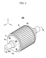
- FIG. 2 schematically illustrates the roll 1000 included in the apparatus for manufacturing compacted iron 500 of FIG. 1 .
- the structure of the roll 1000 of FIG. 2 is shown simply to exemplify the present invention, and the present invention is not limited thereto.
- the shape of the roll 100 may be variously modified.
- the roll 1000 comprises a roll tyre 20 and a roll core 30.
- the roll tyre 20 surrounds a circumference of the roll core 30.
- a plurality of recesses 201 on a surface of the roll tyre 20 are formed to extend along the y-axis direction.
- corrugated compacted irons can be continuously manufactured by rotating the roll 100 and compressing powder into the compacted irons with the plurality of recesses 201.
- the roll tyre 20 compresses the powder while contacting the powder with a high temperature, the roll tyre 20 may be thermally deformed or damaged.
- the roll tyre 20 is heated and is removed from the roll core 30, the roll tyre is repaired to be reused or is exchanged with a new product.
- the roll core 30 comprises a shaft 301 extending in the y-axis direction.
- a cooling passage 3011 is formed in the shaft 301 along the y-axis direction. Cooling fluid flowing through the cooling passage 3011 cools the heated roll tyre 20 and roll core 30.
- cooling fluid refers to any material including water, capable of cooling the high temperature roll tyre 20 and roll core 30. Thus, any medium other than water may be used as cooling fluid.
- the roll tyre 20 When the roll 1000 rotates at a high speed, the roll tyre 20 is slid by a rotating force, thereby causing a scratch or a gap on border surfaces where the roll tyre 20 and the roll core 30 contact each other. As a result, the cooling fluid which cools the roll tyre 20 while flowing along the cooling passage 3011 (see FIG. 3 ) formed on the border surface thereof can be leaked to the outside.
- the border surfaces where the roll tyre 20 and the roll core 30 contact each other are sealed by using sealing grooves 10 (see FIG. 3 ), etc.
- a cooling fluid can be interrupted from being leaked to the outside.
- caps 12 are attached to one side surface of the roll core 30.
- the caps 12 are spaced apart from each other about the shaft 301 by a regular interval to be attached to a side surface of the roll core 30.
- a total of four caps 13 including the shown three caps 12 are spaced apart from each other by a regular interval to be attached to the side surface of the roll core 30.
- the caps 12 are attached to another side surface of the roll core 30.
- the caps 12 seal second sealing passages 19 (see FIG. 3 ) extending in the y-axis direction in the roll core 30. The caps 12 prevent foreign substances from penetrating the roll core 30.
- the second sealing passages 19 are also spaced apart from each other by a substantially regular interval to be formed in the roll core 30.
- the structure of the roll 1000 for sealing a cooling fluid will be described in more detail with reference to FIG. 3 .
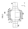
- FIG. 3 shows a schematic cross-sectional structure of the roll 1000 of FIG. 2 taken along direction III-III.
- the structure of the roll 1000 of FIG. 3 is shown simply to exemplify the present invention, and the present invention is not limited thereto. Thus, the structure of the roll 1000 may be modified to another form.
- the cooling passage 3011 through which the cooling fluid circulates is formed in the roll 1000.
- the cooling fluid supplied along the cooling passage 3011 (indicated by a dotted line) formed at the center of the shaft 301 contacts the roll tyre 30 while spirally rotating along the cooling passage 3011 formed on the border surfaces.
- compacted irons can be continuously manufactured as the cooling fluid cools the roll tyre 30 while preventing thermal deformation of the roll tyre 30.
- the cooling passage 3011 is formed in the roll tyre 20 in FIG. 3
- a cooling passage may be formed in the roll core 30.
- a pair of sealing grooves 10 are located along the y-axis direction to be spaced apart from the cooling passage 3011 formed on the border surface 25 side by side with the cooling passage 3011.
- the sealing grooves 10 vertically facing each other are the same as each other.
- the sealing grooves 10 vertically facing each other are continuously connected while forming ring-shapes along the border surface 25. That is, the sealing grooves 10 are formed in a circumferential direction of the roll core 30, i.e. a direction parallel to the z-axis, along the border surface, in more detail, along surfaces 303 of the roll core 30.
- the sealing grooves 10 may be formed on surfaces of the roll tyre 20.
- the cooling passage 3011 formed on the border surface 25 is located between the pair of sealing grooves 10.
- a sealing material 60 is filled in the pair of sealing grooves 10 to prevent the cooling fluid from being leaked to the outside. That is, the border surface 25 can be sealed by using the pair of sealing grooves 10.
- the roll core 30 has a first sealing passage 17 and a second sealing passage 19.
- the first sealing passage 17 extends in a direction crossing a direction along which the shaft 301 extends, i.e. in the z-axis direction and is connected to the sealing groove 10.
- the second sealing passage 19 extends in a direction parallel to a direction along which the shaft 301 extends, i.e. in the y-axis direction and is connected to the first sealing passage 17.
- a process of sealing a cooling fluid will be described in more detail with reference to FIG. 4 .
- FIG. 4 schematically shows a process of sealing a cooling fluid at portion IV of FIG. 3 .
- the sealing process of FIG. 4 is shown simply to exemplify the present invention, and the present invention is not limited thereto.
- the sealing material 60 heated to a specific temperature range is compulsorily fed in a bent arrow direction through the first sealing passage 17 and the second sealing passage 19 with the cap 12 being opened.
- the sealing material 60 When the sealing material 60 is compulsorily fed by using only one first sealing passage 17 and one second sealing passage 19, the sealing material 60 is filled in the remaining three first sealing passages (not shown) and the remaining three second sealing passages (not shown) communicated with the sealing groove 10 after being filled in the sealing groove 10.
- the cap 12 can be closed after it is confirmed that the three first sealing passages (not shown) and the three second sealing passages (not shown) are completely filled with the sealing material 60.
- the sealing material 60 may be heated to 70°C to 80°C to have a viscosity before used. As a result, the sealing material 60 may be filled in the sealing grooves 10. As the four first sealing passages 17 and the four second sealing passages 19 are formed in the roll core 30 to be communicated with the sealing grooves 10, the sealing material 60 can be efficiently filled in the sealing grooves 10 through the four first sealing passages 17 and the four second sealing passages 19. Meanwhile, the roll tyre 20 and the roll core 30 may be rotated after the sealing material 60 is filled in the sealing grooves 10.
- the cap 12 is coupled to one end 191 of the second sealing passage 19 to seal the end 191 of the second sealing passage 19.
- the end 191 is formed on a side surface of the roll core 30.
- the sealing material 60 is so highly viscous that if the liquefied filling material 60 is filled in the roll core 30 through the end 191, the filling material 60 is not leaked from the end 191 but is easily solidified within the roll core 30.
- a threaded groove 1911 is formed at the end 191 and a thread 121 is formed in the cap 12.
- the cap 12 is firmly coupled to the end 191 through coupling of the threaded groove 1911 and the thread 121.
- the filling material 60 is not easily leaked to the outside.
- the sealing material 60 comprises a rubber.
- the rubber comprises a natural rubber or a synthetic rubber. Since a rubber is used for the sealing material 60, the border surfaces 25 of the roll tyre 20 and the roll core 30 can be efficiently sealed. Further, the rubber can be used in a high temperature environment of approximately 150°C to 200°C and thus is suitable for the sealing material 60. In addition, the rubber is elastic and thus can efficiently cope with vibrations due to rotations of the roll tyre 20 and the roll core 30.
- the sealing material 60 may further include graphite. Graphite is contained in the sealing material 60 to increase the melting point of the sealing material 60.
- the sealing material 60 may further comprise suitable materials.
- the melting point of the sealing material 60 may be 600°C to 800°C. When the melting point of the sealing material is too low, the sealing material 60 may be melted, which makes it difficult to seal the border surfaces 25. Meanwhile, when the melting point of the sealing material 60 is too high, the sealing material 60 is hardened to be too hard that the elasticity thereof is reduced.
- the shape of the sealing groove 10 will be described in more detail with reference to FIG. 5 .
- FIG. 5 schematically shows an enlarged cross-sectional structure of the sealing groove 10.
- the roll tyre 20 will be omitted in FIG. 5 for convenience of description.
- FIG. 5 shows a sealing groove 10 which is not connected to the first sealing passage 17 (see FIG. 4 ).
- the sealing groove 10 comprises a central part 101 and a pair of steps 103.
- the central part 101 is recessed toward the roll tyre 20 (see FIG. 4 ).
- the pair of steps 103 are formed on opposite sides of the central part 101.
- the pair of steps 103 are convexly formed toward the roll tyre 20 (see FIG. 4 ).
- the sealing groove 10 can stably accommodate the sealing material 60 (see FIG. 4 , the same hereinbelow) at the central part 101 and can prevent the sealing material 60 from overflowing to the outside of the sealing groove 10 due to the pair of steps 103.
- the ratio of the radius of curvature 101r r of the central part to the radius of curvature 103r of the steps 103 may be 4 to 10.
- the ratio is less than 4
- the size of the central part 101 is too small that the sealing groove 10 may not accommodate an adequate amount of the sealing material 60 necessary for sealing.
- the ratio is more than 10 since the size of the steps 103 is too small that the sealing material 60 accommodated in the sealing groove 10 may easily overflow to the outside.
- an imaginary plane 101p comprising a center 101c of the central part 101 may be considered.
- the imaginary plane 101p is formed along the center 101c of the central part 101.
- the imaginary plane 101p is formed in parallel to the zx plane of FIG. 2 . That is, the imaginary plane 101p extends in a direction crossing a direction in which the shaft 301 (see FIG. 2 ) extends.
- the directions (indicated by dotted lines) in which the pair of steps 103 face are inclined toward the imaginary plane 101 p.
- the sealing material 60 can be stably accommodated in the sealing groove 10.
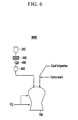
- FIG. 6 schematically shows an apparatus for manufacturing molten iron 9000 comprsing the apparatus for manufacturing compacted iron 500 of FIG. 1 .
- the apparatus for manufacturing molten iron 9000 comprises an apparatus for manufacturing compatecd iron 500 and a melter-gasifier 60.
- the melter-gasifier 60 receives lump coals or coal briquettes and compacted irons to manufacture molten iron.
- the apparatus for manufacturing molten iron 9000 may further comprise a powder storage bin 200, a crusher 400, and a storage vessel 600.
- the powder storage bin 200 stores powder.
- the crusher 400 receives compacted irons from the apparatus for manufacturing compacted iron 500 to crush the compacted irons.
- the storage vessel 60 temporarily stores the crushed compacted irons and then supplies the stored compacted irons to the melter-gasifier 700.
- the detailed structure of the melter-gasifer 60 can be easily understood by those skilled in the art to which the present invention pertains, and a detailed description thereof will be omitted.
- the lump coals or coal briquettes supplied to the melter-gasifier 60 serve as a heat source for smelting the compacted irons while being heated by oxygen.
- the compacted irons are smelted to manufacture molten iron.
Landscapes
- Engineering & Computer Science (AREA)
- Chemical & Material Sciences (AREA)
- Manufacturing & Machinery (AREA)
- Materials Engineering (AREA)
- Metallurgy (AREA)
- Organic Chemistry (AREA)
- Life Sciences & Earth Sciences (AREA)
- Environmental & Geological Engineering (AREA)
- General Life Sciences & Earth Sciences (AREA)
- Geochemistry & Mineralogy (AREA)
- Geology (AREA)
- Mechanical Engineering (AREA)
- Furnace Details (AREA)
- Casting Or Compression Moulding Of Plastics Or The Like (AREA)
- Powder Metallurgy (AREA)
Abstract
Description
- This application claims priority to and the benefit of Korean Patent Application No.
10-2009-0087826 - The present invention relates to an apparatus for manufacturing compacted iron and an apparatus for manufacturing molten iron comprising the same, , and more particularly, to an apparatus for manufacturing compacted iron which can firmly seal a cooling fluid circulating in a roll tyre and an apparatus for manufacturing molten iron comprising the same.
- In a smelting reduction process, lump coal and compacted reduced iron are used and charged into a melter-gasifier to manufacture molten iron. Thus, compacted reduced irons, i.e. compacted irons are manufactured by reducing fine ores and are charged to a melter-gasifier.
- The compacted irons are manufactured by compacting direct reduced irons (DRIs). The continuous compacted irons are manufactured by introducing the direct reduced irons into a gap between a pair of rolls and driving the pair of rolls to compress the direct reduced iron. Here, each of the rolls includes a roll core and a ring-shaped roll tyre coupled to the periphery thereof.
- The above information disclosed in this Background section is only for enhancement of understanding of the background of the invention and therefore it may contain information that does not form the prior art that is already known in this country to a person of ordinary skill in the art.
- The present invention has been made in an effort to provide an apparatus for manufacturing compacted iron which can firmly seal a cooling fluid circulating in a roll tyre. Further, the present invention has been made in an effort to provide an apparatus for manufacturing molten iron comprising the above-mentioned apparatus for manufacturing compacted iron.
- An exemplary embodiment of the present invention provides an apparatus for manufacturing compacted iron, comprising: i) a roll core comprising a shaft; and ii) a roll tyre surrounding a circumference of the roll core and having a recess on a surface thereof applied such that compacted irons are manufactured by compressing powder to the compacted irons. A cooling passage through which a cooling fluid applied to cool the roll tyre flows is formed on border surfaces where the roll tyre and the roll core contact each other, and at least one sealing groove located in parallel to the cooling passage and spaced apart from the cooling passage and applied to seal the border surfaces is formed on the border surfaces.
- The at least one sealing groove may comprise a pair of sealing grooves, and the cooling passage may be located between the pair of sealing grooves. A sealing material may be filled in the sealing groove. The sealing material may comprise a rubber. The sealing material may further comprise graphite. The melting point of the sealing material may be 600°C to 800°C. The sealing groove may be formed along a surface of the roll core in a circumferential direction of the roll core. The sealing groove may comprise: i) a central part recessed toward the roll tyre; and ii) a pair of steps formed on opposite sides of the central part and convexly formed toward the roll tyre. A ratio of the radius of curvature of the central part to the radius of curvature of one step of the pair of steps may be 4 to 10. Directions in which the pair of steps face may be inclined toward an imaginary plane including the center of the central part in directions crossing a direction along which the shaft extends. The roll core may comprise: i) at least one first sealing passage extending in a direction crossing a direction along which the shaft extends and connected to the sealing groove; and ii) at least one second sealing passage extending in a direction parallel to the direction along which the shaft extends and connected to the first sealing passage, one end of the at least one second sealing passage being formed on a side surface of the roll core. The sealing material for filling the sealing groove may be applied to be compulsorily fed through the first sealing passage and the second sealing passage. The at least one second sealing passage may comprise a plurality of second sealing passages and the plurality of second sealing passages may be spaced apart from each other at a substantially regular interval.
- The apparatus for manufacturing compacted iron according to an exemplary embodiment of the present invention may further comprise: a cap coupled to the end of the second sealing passage to seal the end of the second sealing passage. A threaded groove may be formed at the end of the second sealing passage and the cap may be coupled to the threaded groove.
- Another exemplary embodiment of the present invention provides an apparatus for manufacturing molten iron, comprising: i) an apparatus for manufacturing compacted iron; and ii) a melter-gasifier for receiving compacted irons from the apparatus for manufacturing compacted iron to manufacture molten iron.
- The apparatus for manufacturing compacted iron comprising: i) a roll core comprising a shaft; and ii) a roll tyre surrounding a circumference of the roll core and having a recess on a surface thereof applied such that compacted irons are manufactured by compressing powder to the compacted irons. A cooling passage through which a cooling fluid applied to cool the roll tyre flows is formed on border surfaces where the roll tyre and the roll core contact each other, and at least one sealing groove located in parallel to the cooling passage and spaced apart from the cooling passage and applied to seal the border surfaces is formed on the border surfaces.
- According to the exemplary embodiments of the present invention, it is possible to prevent a roll tyre rotating in a high temperature from being pushed out and a cooling fluid from being discharged to the outside of the roll tyre. As a result, a lifespan of the roll tyre can be increased. Further, since the roll tyre can be efficiently cooled by the sealed cooling fluid, compacted irons can be stably manufactured continuously. Accordingly, compacted irons and molten iron can be efficiently manufactured.
-
-
FIG. 1 is a schematic perspective view of an apparatus for manufacturing compacted iron according to an exemplary embodiment of the present invention. -
FIG. 2 is a schematic perspective view of a roll included in the apparatus for manufacturing compacted iron ofFIG. 1 . -
FIG. 3 is a schematic cross-sectional view of the roll ofFIG. 2 taken along direction III-III. -
FIG. 4 is a view schematically showing a process of sealing portion IV ofFIG. 3 . -
FIG. 5 is a schematic enlarged cross-sectional view of a sealing groove. -
FIG. 6 is a schematic view of an apparatus for manufacturing molten iron comprising the apparatus for manufacturing compacted iron ofFIG. 1 . -
FIG. 1 is a schematic perspective view of an apparatus for manufacturing compactediron 500 according to the first embodiment of the present invention. The structure of the apparatus for manufacturing compactediron 500 ofFIG. 1 is shown simply to exemplify the present invention, and the present invention is not limited thereto. Thus, the structure of the apparatus for manufacturing compactediron 500 may be variously modified. - As shown in
FIG. 1 , the apparatus for manufacturing compactediron 500 comprises ancharging hopper 50, a pair ofscrew feeders 52, and a pair ofrolls 1000. The pair ofrolls 1000 is fixed within acasing 54. In addition, the apparatus for manufacturing compactediron 500 may further comprise other parts. - As shown in
FIG. 1 , powder, e.g. direct reduced irons (DRIs) are charged into thecharging hopper 50 through asupply port 501 of thecharging hopper 50 along the -z-axis direction. AlthoughFIG. 1 illustrates that direct reduced irons are used as powder, any materials other than the direct reduced irons may be used as powder. - Direct reduced irons may be manufactured by charging and fluidizing fine ores into a fluidized bed reduction furnace into which reducing gas is supplied and reducing the fine ores. The powder manufactured through the process is introduced between the pair of
rolls 1000 by using the pair ofscrew feeders 52 installed within thecharging hopper 50. The pair ofrolls 1000 compress the powder while rotating in opposite directions to manufacture compacted irons. - As shown in
FIG. 1 , the gas generated by the powder is exhausted to the outside throughexhaust ports 503 installed in thecharging hopper 50. As gas is removed from the powder, the powder can be compressed well without leaving air gaps. Hereinafter, the structure of aroll 1000 included in the apparatus for manufacturing compactediron 500 ofFIG. 1 will be described in more detail with reference toFIG. 2 . -
FIG. 2 schematically illustrates theroll 1000 included in the apparatus for manufacturing compactediron 500 ofFIG. 1 . The structure of theroll 1000 ofFIG. 2 is shown simply to exemplify the present invention, and the present invention is not limited thereto. Thus, the shape of the roll 100 may be variously modified. - As shown in
FIG. 2 , theroll 1000 comprises aroll tyre 20 and aroll core 30. Theroll tyre 20 surrounds a circumference of theroll core 30. A plurality ofrecesses 201 on a surface of theroll tyre 20 are formed to extend along the y-axis direction. Thus, corrugated compacted irons can be continuously manufactured by rotating the roll 100 and compressing powder into the compacted irons with the plurality ofrecesses 201. As theroll tyre 20 compresses the powder while contacting the powder with a high temperature, theroll tyre 20 may be thermally deformed or damaged. Thus, periodically theroll tyre 20 is heated and is removed from theroll core 30, the roll tyre is repaired to be reused or is exchanged with a new product. - As shown in
FIG. 2 , theroll core 30 comprises ashaft 301 extending in the y-axis direction. Acooling passage 3011 is formed in theshaft 301 along the y-axis direction. Cooling fluid flowing through thecooling passage 3011 cools theheated roll tyre 20 androll core 30. Here, cooling fluid refers to any material including water, capable of cooling the hightemperature roll tyre 20 androll core 30. Thus, any medium other than water may be used as cooling fluid. - When the
roll 1000 rotates at a high speed, theroll tyre 20 is slid by a rotating force, thereby causing a scratch or a gap on border surfaces where theroll tyre 20 and theroll core 30 contact each other. As a result, the cooling fluid which cools theroll tyre 20 while flowing along the cooling passage 3011 (seeFIG. 3 ) formed on the border surface thereof can be leaked to the outside. - Thus, in the exemplary embodiment of the present invention, the border surfaces where the
roll tyre 20 and theroll core 30 contact each other are sealed by using sealing grooves 10 (seeFIG. 3 ), etc. As a result, a cooling fluid can be interrupted from being leaked to the outside. - As shown in
FIG. 2 , caps 12 are attached to one side surface of theroll core 30. Thecaps 12 are spaced apart from each other about theshaft 301 by a regular interval to be attached to a side surface of theroll core 30. For example, although onecap 12 is not shown inFIG. 2 , a total of four caps 13 including the shown threecaps 12 are spaced apart from each other by a regular interval to be attached to the side surface of theroll core 30. Although not shown inFIG. 2 , thecaps 12 are attached to another side surface of theroll core 30. Thecaps 12 seal second sealing passages 19 (seeFIG. 3 ) extending in the y-axis direction in theroll core 30. Thecaps 12 prevent foreign substances from penetrating theroll core 30. As thecaps 12 are spaced apart from each other by a regular interval, the second sealing passages 19 (seeFIG. 3 ) are also spaced apart from each other by a substantially regular interval to be formed in theroll core 30. Hereinafter, the structure of theroll 1000 for sealing a cooling fluid will be described in more detail with reference toFIG. 3 . -
FIG. 3 shows a schematic cross-sectional structure of theroll 1000 ofFIG. 2 taken along direction III-III. The structure of theroll 1000 ofFIG. 3 is shown simply to exemplify the present invention, and the present invention is not limited thereto. Thus, the structure of theroll 1000 may be modified to another form. - As shown in
FIG. 3 , thecooling passage 3011 through which the cooling fluid circulates is formed in theroll 1000. The cooling fluid supplied along the cooling passage 3011 (indicated by a dotted line) formed at the center of theshaft 301 contacts theroll tyre 30 while spirally rotating along thecooling passage 3011 formed on the border surfaces. Thus, compacted irons can be continuously manufactured as the cooling fluid cools theroll tyre 30 while preventing thermal deformation of theroll tyre 30. Although thecooling passage 3011 is formed in theroll tyre 20 inFIG. 3 , a cooling passage may be formed in theroll core 30. - As shown in
FIG. 3 , a pair of sealinggrooves 10 are located along the y-axis direction to be spaced apart from thecooling passage 3011 formed on theborder surface 25 side by side with thecooling passage 3011. Although four sealinggrooves 10 are formed inFIG. 3 , the sealinggrooves 10 vertically facing each other are the same as each other. The sealinggrooves 10 vertically facing each other are continuously connected while forming ring-shapes along theborder surface 25. That is, the sealinggrooves 10 are formed in a circumferential direction of theroll core 30, i.e. a direction parallel to the z-axis, along the border surface, in more detail, alongsurfaces 303 of theroll core 30. Although the sealinggrooves 10 are formed on thesurfaces 303 of theroll core 30 inFIG. 3 , the sealinggrooves 10 may be formed on surfaces of theroll tyre 20. - The
cooling passage 3011 formed on theborder surface 25 is located between the pair of sealinggrooves 10. Thus, when an aperture is generated between theroll tyre 20 and theroll core 30 by the rotations of theroll tyre 20 and theroll core 30 so that when the cooling fluid can be leaked to the outside along theborder surface 25, a sealing material 60 (seeFIG. 4 ) is filled in the pair of sealinggrooves 10 to prevent the cooling fluid from being leaked to the outside. That is, theborder surface 25 can be sealed by using the pair of sealinggrooves 10. - As shown in
FIG. 3 , theroll core 30 has afirst sealing passage 17 and asecond sealing passage 19. Thefirst sealing passage 17 extends in a direction crossing a direction along which theshaft 301 extends, i.e. in the z-axis direction and is connected to the sealinggroove 10. Further, thesecond sealing passage 19 extends in a direction parallel to a direction along which theshaft 301 extends, i.e. in the y-axis direction and is connected to thefirst sealing passage 17. Hereinafter, a process of sealing a cooling fluid will be described in more detail with reference toFIG. 4 . -
FIG. 4 schematically shows a process of sealing a cooling fluid at portion IV ofFIG. 3 . The sealing process ofFIG. 4 is shown simply to exemplify the present invention, and the present invention is not limited thereto. - As shown in
FIG. 4 , as theroll tyre 20 and theroll core 30 rotate, a gap between theroll tyre 20 and theroll core 30 may widen, causing a cooling fluid L from being leaked from the cooling passage 3011 (seeFIG. 3 ). In this case, as indicated by an arrow, the sealingmaterial 60 heated to a specific temperature range is compulsorily fed in a bent arrow direction through thefirst sealing passage 17 and thesecond sealing passage 19 with thecap 12 being opened. When the sealingmaterial 60 is compulsorily fed by using only onefirst sealing passage 17 and onesecond sealing passage 19, the sealingmaterial 60 is filled in the remaining three first sealing passages (not shown) and the remaining three second sealing passages (not shown) communicated with the sealinggroove 10 after being filled in the sealinggroove 10. Thus, thecap 12 can be closed after it is confirmed that the three first sealing passages (not shown) and the three second sealing passages (not shown) are completely filled with the sealingmaterial 60. - The sealing
material 60 may be heated to 70°C to 80°C to have a viscosity before used. As a result, the sealingmaterial 60 may be filled in the sealinggrooves 10. As the fourfirst sealing passages 17 and the foursecond sealing passages 19 are formed in theroll core 30 to be communicated with the sealinggrooves 10, the sealingmaterial 60 can be efficiently filled in the sealinggrooves 10 through the fourfirst sealing passages 17 and the foursecond sealing passages 19. Meanwhile, theroll tyre 20 and theroll core 30 may be rotated after the sealingmaterial 60 is filled in the sealinggrooves 10. - Meanwhile, the
cap 12 is coupled to one end 191 of thesecond sealing passage 19 to seal the end 191 of thesecond sealing passage 19. The end 191 is formed on a side surface of theroll core 30. The sealingmaterial 60 is so highly viscous that if the liquefied fillingmaterial 60 is filled in theroll core 30 through the end 191, the fillingmaterial 60 is not leaked from the end 191 but is easily solidified within theroll core 30. A threadedgroove 1911 is formed at the end 191 and athread 121 is formed in thecap 12. Thus, thecap 12 is firmly coupled to the end 191 through coupling of the threadedgroove 1911 and thethread 121. As a result, the fillingmaterial 60 is not easily leaked to the outside. - The sealing
material 60 comprises a rubber. The rubber comprises a natural rubber or a synthetic rubber. Since a rubber is used for the sealingmaterial 60, the border surfaces 25 of theroll tyre 20 and theroll core 30 can be efficiently sealed. Further, the rubber can be used in a high temperature environment of approximately 150°C to 200°C and thus is suitable for the sealingmaterial 60. In addition, the rubber is elastic and thus can efficiently cope with vibrations due to rotations of theroll tyre 20 and theroll core 30. - The sealing
material 60 may further include graphite. Graphite is contained in the sealingmaterial 60 to increase the melting point of the sealingmaterial 60. In addition, the sealingmaterial 60 may further comprise suitable materials. The melting point of the sealingmaterial 60 may be 600°C to 800°C. When the melting point of the sealing material is too low, the sealingmaterial 60 may be melted, which makes it difficult to seal the border surfaces 25. Meanwhile, when the melting point of the sealingmaterial 60 is too high, the sealingmaterial 60 is hardened to be too hard that the elasticity thereof is reduced. Hereinafter, the shape of the sealinggroove 10 will be described in more detail with reference toFIG. 5 . -
FIG. 5 schematically shows an enlarged cross-sectional structure of the sealinggroove 10. Theroll tyre 20 will be omitted inFIG. 5 for convenience of description. Further,FIG. 5 shows a sealinggroove 10 which is not connected to the first sealing passage 17 (seeFIG. 4 ). - As shown in
FIG. 5 , the sealinggroove 10 comprises acentral part 101 and a pair ofsteps 103. Thecentral part 101 is recessed toward the roll tyre 20 (seeFIG. 4 ). Further, the pair ofsteps 103 are formed on opposite sides of thecentral part 101. The pair ofsteps 103 are convexly formed toward the roll tyre 20 (seeFIG. 4 ). Thus, the sealinggroove 10 can stably accommodate the sealing material 60 (seeFIG. 4 , the same hereinbelow) at thecentral part 101 and can prevent the sealingmaterial 60 from overflowing to the outside of the sealinggroove 10 due to the pair ofsteps 103. - Here, the ratio of the radius of
curvature 101r r of the central part to the radius of curvature 103r of thesteps 103 may be 4 to 10. When the ratio is less than 4, the size of thecentral part 101 is too small that the sealinggroove 10 may not accommodate an adequate amount of the sealingmaterial 60 necessary for sealing. In addition, when the ratio is more than 10, since the size of thesteps 103 is too small that the sealingmaterial 60 accommodated in the sealinggroove 10 may easily overflow to the outside. Thus, it is preferable to maintain the ratio of the radius ofcurvature 101r r of thecentral part 101 to the radius of curvature 103r of thesteps 103 in the above-mentioned range. - Meanwhile, as shown in
FIG. 5 , animaginary plane 101p comprising acenter 101c of thecentral part 101 may be considered. Theimaginary plane 101p is formed along thecenter 101c of thecentral part 101. Thus, theimaginary plane 101p is formed in parallel to the zx plane ofFIG. 2 . That is, theimaginary plane 101p extends in a direction crossing a direction in which the shaft 301 (seeFIG. 2 ) extends. Here, the directions (indicated by dotted lines) in which the pair ofsteps 103 face are inclined toward theimaginary plane 101 p. Thus, since the pair ofsteps 103 are inclinedly formed, the sealingmaterial 60 can be stably accommodated in the sealinggroove 10. -
FIG. 6 schematically shows an apparatus for manufacturingmolten iron 9000 comprsing the apparatus for manufacturingcompacted iron 500 ofFIG. 1 . - As shown in
FIG. 6 , the apparatus for manufacturingmolten iron 9000 comprises an apparatus formanufacturing compatecd iron 500 and a melter-gasifier 60. Here, the melter-gasifier 60 receives lump coals or coal briquettes and compacted irons to manufacture molten iron. In addition, the apparatus for manufacturingmolten iron 9000 may further comprise apowder storage bin 200, acrusher 400, and astorage vessel 600. Thepowder storage bin 200 stores powder. Further, thecrusher 400 receives compacted irons from the apparatus for manufacturingcompacted iron 500 to crush the compacted irons. Thestorage vessel 60 temporarily stores the crushed compacted irons and then supplies the stored compacted irons to the melter-gasifier 700. The detailed structure of the melter-gasifer 60 can be easily understood by those skilled in the art to which the present invention pertains, and a detailed description thereof will be omitted. - As shown in
FIG. 6 , the lump coals or coal briquettes supplied to the melter-gasifier 60 serve as a heat source for smelting the compacted irons while being heated by oxygen. Thus, the compacted irons are smelted to manufacture molten iron. - Although the present invention has been described in the above description, it will be easily understood by those skilled in the art to which the present invention pertains that various changes and modification can be made without departing from the concepts and ranges of the following claims.
- While this invention has been described in connection with what is presently considered to be practical exemplary embodiments, it is to be understood that the invention is not limited to the disclosed embodiments, but, on the contrary, is intended to cover various modifications and equivalent arrangements included within the spirit and scope of the appended claims.
Claims (16)
- An apparatus for manufacturing compacted iron, comprising:a roll core comprising a shaft; anda roll tyre surrounding a circumference of the roll core and having a recess on a surface thereof applied such that compacted irons are manufactured by compressing powder to the compacted irons,wherein a cooling passage through which a cooling fluid applied to cool the roll tyre flows is formed on border surfaces where the roll tyre and the roll core contact each other, andat least one sealing groove located in parallel to the cooling passage to be spaced apart from the cooling passage and applied to seal the border surfaces is formed on the border surfaces.
- The apparatus for manufacturing compacted iron of claim 1, wherein the at least one sealing groove comprises a pair of sealing grooves, and the cooling passage is located between the pair of sealing grooves.
- The apparatus for manufacturing compacted iron of claim 2, wherein a sealing material is filled in the sealing groove.
- The apparatus for manufacturing compacted iron of claim 3, wherein the sealing material comprises a rubber.
- The apparatus for manufacturing compacted iron of claim 4, wherein the sealing material further comprises graphite.
- The apparatus for manufacturing compacted iron of claim 4, wherein the melting point of the sealing material is 600°C to 800°C.
- The apparatus for manufacturing compacted iron of claim 2, wherein the sealing groove is formed along a surface of the roll core in a circumferential direction of the roll core.
- The apparatus for manufacturing compacted iron of claim 7, wherein
the sealing groove comprises:a central part recessed toward the roll tyre; anda pair of steps formed on opposite sides of the central part and convexly formed toward the roll tyre. - The apparatus for manufacturing compacted iron of claim 8, wherein a ratio of the radius of curvature of the central part to the radius of curvature of one step of the pair of steps is 4 to 10.
- The apparatus for manufacturing compacted iron of claim 8, wherein directions in which the pair of steps face are inclined toward an imaginary plane including the center of the central part in directions crossing a direction along which the shaft extends.
- The apparatus for manufacturing compacted iron of claim 7, wherein
the roll core comprises:at least one first sealing passage extending in a direction crossing a direction along which the shaft extends and connected to the sealing groove; andat least one second sealing passage extending in a direction parallel to the direction along which the shaft extends and connected to the first sealing passage, one end of the at least one second sealing passage being formed on a side surface of the roll core. - The apparatus for manufacturing compacted iron of claim 11, wherein the sealing material for filling the sealing groove is applied to be compulsorily fed through the first sealing passage and the second sealing passage.
- The apparatus for manufacturing compacted iron of claim 11, wherein the at least one second sealing passage includes a plurality of second sealing passages and the plurality of second sealing passages are spaced apart from each other by a regular interval.
- The apparatus for manufacturing compacted iron of claim 11, further comprising:a cap coupled to the end of the second sealing passage to seal the end of the second sealing passage.
- The apparatus for manufacturing compacted iron of claim 14, wherein a threaded groove is formed at the end of the second sealing passage and the cap is coupled to the threaded groove.
- An apparatus for manufacturing molten iron, comprising:an apparatus for manufacturing compacted iron; anda melter-gasifer for receiving compacted irons from the apparatus for manufacturing compacted iron to manufacture molten iron,wherein the apparatus for manufacturing compacted iron comprises:a roll core comprising a shaft; anda roll tyre surrounding a circumference of the roll core and having a recess on a surface thereof applied such that compacted irons are manufactured by compressing powder to the compacted irons, andwherein a cooling passage through which a cooling fluid applied to cool the roll tyre flows is formed on border surfaces where the roll tyre and the roll core contact each other, andat least one sealing groove located in parallel to the cooling passage and spaced apart from the cooling passage and applied to seal the border surfaces is formed on the border surfaces.
Applications Claiming Priority (2)
| Application Number | Priority Date | Filing Date | Title |
|---|---|---|---|
| KR1020090087826A KR101050804B1 (en) | 2009-09-17 | 2009-09-17 | Compacted material manufacturing apparatus and molten iron manufacturing apparatus including the same |
| PCT/KR2010/004098 WO2011034275A1 (en) | 2009-09-17 | 2010-06-24 | Apparatus for manufacturing compacted iron, and apparatus for manufacturing molten iron comprising the apparatus |
Publications (3)
| Publication Number | Publication Date |
|---|---|
| EP2479295A1 true EP2479295A1 (en) | 2012-07-25 |
| EP2479295A4 EP2479295A4 (en) | 2017-01-04 |
| EP2479295B1 EP2479295B1 (en) | 2019-02-20 |
Family
ID=43758849
Family Applications (1)
| Application Number | Title | Priority Date | Filing Date |
|---|---|---|---|
| EP10817344.4A Not-in-force EP2479295B1 (en) | 2009-09-17 | 2010-06-24 | Apparatus for manufacturing compacted iron, and apparatus for manufacturing molten iron comprising the apparatus |
Country Status (4)
| Country | Link |
|---|---|
| EP (1) | EP2479295B1 (en) |
| KR (1) | KR101050804B1 (en) |
| CN (1) | CN102498222B (en) |
| WO (1) | WO2011034275A1 (en) |
Families Citing this family (3)
| Publication number | Priority date | Publication date | Assignee | Title |
|---|---|---|---|---|
| KR101405485B1 (en) * | 2012-07-02 | 2014-06-11 | 주식회사 포스코 | Compacting machine |
| CN116618658B (en) * | 2023-04-12 | 2023-12-26 | 唐山曹妃甸区通鑫再生资源回收利用有限公司 | Cooling device for hot-pressed iron block |
| CN116441340B (en) * | 2023-04-26 | 2024-05-21 | 唐山曹妃甸区通鑫再生资源回收利用有限公司 | Hot-pressed iron block manufacturing device and manufacturing method thereof |
Family Cites Families (10)
| Publication number | Priority date | Publication date | Assignee | Title |
|---|---|---|---|---|
| JPS59133334A (en) | 1983-01-20 | 1984-07-31 | Mitsubishi Heavy Ind Ltd | Compression molding machine having mixing function |
| CN2231145Y (en) * | 1995-09-20 | 1996-07-17 | 天津市轧钢一厂 | Roll mechanical balance device for mill |
| DE69731321T2 (en) * | 1996-02-09 | 2005-10-20 | Modern Machinery Co., Ltd., Yokohama | Thin film forming roll, film forming machine and film forming process |
| CN2365444Y (en) * | 1999-01-08 | 2000-02-23 | 徐大刚 | Seal coupling apparatus in rotary roller circulation cooling system |
| AT408199B (en) * | 1999-09-06 | 2001-09-25 | Voest Alpine Ind Anlagen | CASTING ROLLER |
| KR101118285B1 (en) * | 2004-10-19 | 2012-03-20 | 주식회사 포스코 | An apparatus for manufacturing compacted irons of reduced materials comprising fine direct reduced irons and an apparatus for manufacturing molten irons using the same |
| KR101118286B1 (en) * | 2004-12-02 | 2012-03-20 | 주식회사 포스코 | Method for manufacturing compacted irons comprising fine direct reduced irons, an apparatus for manufacturing compacted irons comprising fine direct reduced irons, and an apparatus for manufacturing molten irons using the same |
| KR100784150B1 (en) * | 2006-12-18 | 2007-12-10 | 주식회사 포스코 | Compacted body manufacturing apparatus and molten iron manufacturing apparatus provided with the same |
| KR100797843B1 (en) * | 2006-12-27 | 2008-01-24 | 주식회사 포스코 | Compacted material manufacturing device and molten iron manufacturing device using the same |
| CN201124565Y (en) * | 2007-10-24 | 2008-10-01 | 许志铭 | Improvement of embossing wheel structure for embossing |
-
2009
- 2009-09-17 KR KR1020090087826A patent/KR101050804B1/en not_active Expired - Fee Related
-
2010
- 2010-06-24 EP EP10817344.4A patent/EP2479295B1/en not_active Not-in-force
- 2010-06-24 WO PCT/KR2010/004098 patent/WO2011034275A1/en not_active Ceased
- 2010-06-24 CN CN2010800414609A patent/CN102498222B/en not_active Expired - Fee Related
Non-Patent Citations (1)
| Title |
|---|
| See references of WO2011034275A1 * |
Also Published As
| Publication number | Publication date |
|---|---|
| CN102498222B (en) | 2013-12-04 |
| CN102498222A (en) | 2012-06-13 |
| KR101050804B1 (en) | 2011-07-20 |
| EP2479295B1 (en) | 2019-02-20 |
| WO2011034275A1 (en) | 2011-03-24 |
| KR20110029942A (en) | 2011-03-23 |
| EP2479295A4 (en) | 2017-01-04 |
Similar Documents
| Publication | Publication Date | Title |
|---|---|---|
| EP2479295B1 (en) | Apparatus for manufacturing compacted iron, and apparatus for manufacturing molten iron comprising the apparatus | |
| EP2487265A1 (en) | Molten metal producing device | |
| Kerimov et al. | Use of metallized raw materials in electric furnace steelmaking | |
| CN103998627B (en) | Tuyere assembly and use the molten iron manufacturing apparatus of this tuyere assembly | |
| KR101118285B1 (en) | An apparatus for manufacturing compacted irons of reduced materials comprising fine direct reduced irons and an apparatus for manufacturing molten irons using the same | |
| CN1795279B (en) | Equipment for producing compacted iron including reducing materials of direct reduced iron fines and equipment for producing molten iron using the same | |
| CN101910420A (en) | Reduction furnace and apparatus for manufacturing molten iron including the same | |
| EP2787091B1 (en) | Sealing device of driving section | |
| EP4430216B1 (en) | An apparatus for producing hot briquetted iron | |
| EP3023480B1 (en) | Apparatus for manufacturing coal briquette | |
| EP3088496B1 (en) | Coal briquette manufacturing apparatus | |
| RU2354721C2 (en) | Unit for manufacturing of compressed iron from recycled materials, containing fine-grained directly reduced iron, and facility for manufacturing of molten cast iron, in which this facility is used | |
| CN101563472B (en) | Apparatus for manufacturing compacted irons and apparatus for manufacturing molten iron | |
| CN1842606B (en) | Apparatus for manufacturing compacted irons of reduced materials containing fine direct reduced irons and apparatus for manufacturing molten irons using the same | |
| EP1802780B1 (en) | Apparatus for manufacturing compacted irons of reduced materials comprising fine direct reduced irons and apparatus for manufacturing molten irons using the same | |
| KR101527555B1 (en) | Hci compacting machine and cheek plate for the same | |
| KR20060006493A (en) | Apparatus for producing compacted iron of reduced reducing iron containing reduced iron and apparatus for manufacturing molten iron using the same | |
| CN100529119C (en) | Apparatus for manufacturing compacted irons of reduced materials containing fine direct reduced irons and apparatus for manufacturing molten irons using the same | |
| US20120200013A1 (en) | Apparatus for manufacturing molten metal | |
| KR100711765B1 (en) | Apparatus for producing compacted iron containing reduced-ring iron and apparatus for manufacturing molten iron having same | |
| CN219313679U (en) | Pellet distributing chute | |
| JP2005344181A (en) | Agglomerate including carbonaceous material and its manufacturing method | |
| KR101269146B1 (en) | Apparatus for manufacturing hot comapcted irons and apparatus for manufacturing molten iron comprising the same | |
| US12235047B2 (en) | Method for protecting an inner wall of a shaft furnace | |
| CN207342797U (en) | One kind nitridation silico briquette, which crushes, uses ceramic lining plate |
Legal Events
| Date | Code | Title | Description |
|---|---|---|---|
| PUAI | Public reference made under article 153(3) epc to a published international application that has entered the european phase |
Free format text: ORIGINAL CODE: 0009012 |
|
| 17P | Request for examination filed |
Effective date: 20120413 |
|
| AK | Designated contracting states |
Kind code of ref document: A1 Designated state(s): AL AT BE BG CH CY CZ DE DK EE ES FI FR GB GR HR HU IE IS IT LI LT LU LV MC MK MT NL NO PL PT RO SE SI SK SM TR |
|
| DAX | Request for extension of the european patent (deleted) | ||
| RA4 | Supplementary search report drawn up and despatched (corrected) |
Effective date: 20161205 |
|
| RIC1 | Information provided on ipc code assigned before grant |
Ipc: C21B 13/00 20060101ALI20161129BHEP Ipc: C22B 1/16 20060101AFI20161129BHEP Ipc: C21B 13/14 20060101ALI20161129BHEP |
|
| STAA | Information on the status of an ep patent application or granted ep patent |
Free format text: STATUS: EXAMINATION IS IN PROGRESS |
|
| 17Q | First examination report despatched |
Effective date: 20171018 |
|
| GRAP | Despatch of communication of intention to grant a patent |
Free format text: ORIGINAL CODE: EPIDOSNIGR1 |
|
| STAA | Information on the status of an ep patent application or granted ep patent |
Free format text: STATUS: GRANT OF PATENT IS INTENDED |
|
| INTG | Intention to grant announced |
Effective date: 20180907 |
|
| GRAS | Grant fee paid |
Free format text: ORIGINAL CODE: EPIDOSNIGR3 |
|
| GRAA | (expected) grant |
Free format text: ORIGINAL CODE: 0009210 |
|
| STAA | Information on the status of an ep patent application or granted ep patent |
Free format text: STATUS: THE PATENT HAS BEEN GRANTED |
|
| AK | Designated contracting states |
Kind code of ref document: B1 Designated state(s): AL AT BE BG CH CY CZ DE DK EE ES FI FR GB GR HR HU IE IS IT LI LT LU LV MC MK MT NL NO PL PT RO SE SI SK SM TR |
|
| REG | Reference to a national code |
Ref country code: GB Ref legal event code: FG4D |
|
| REG | Reference to a national code |
Ref country code: CH Ref legal event code: EP |
|
| REG | Reference to a national code |
Ref country code: DE Ref legal event code: R096 Ref document number: 602010057108 Country of ref document: DE |
|
| REG | Reference to a national code |
Ref country code: AT Ref legal event code: REF Ref document number: 1098254 Country of ref document: AT Kind code of ref document: T Effective date: 20190315 |
|
| REG | Reference to a national code |
Ref country code: IE Ref legal event code: FG4D |
|
| REG | Reference to a national code |
Ref country code: LT Ref legal event code: MG4D Ref country code: NL Ref legal event code: MP Effective date: 20190220 |
|
| PG25 | Lapsed in a contracting state [announced via postgrant information from national office to epo] |
Ref country code: SE Free format text: LAPSE BECAUSE OF FAILURE TO SUBMIT A TRANSLATION OF THE DESCRIPTION OR TO PAY THE FEE WITHIN THE PRESCRIBED TIME-LIMIT Effective date: 20190220 Ref country code: LT Free format text: LAPSE BECAUSE OF FAILURE TO SUBMIT A TRANSLATION OF THE DESCRIPTION OR TO PAY THE FEE WITHIN THE PRESCRIBED TIME-LIMIT Effective date: 20190220 Ref country code: PT Free format text: LAPSE BECAUSE OF FAILURE TO SUBMIT A TRANSLATION OF THE DESCRIPTION OR TO PAY THE FEE WITHIN THE PRESCRIBED TIME-LIMIT Effective date: 20190620 Ref country code: NO Free format text: LAPSE BECAUSE OF FAILURE TO SUBMIT A TRANSLATION OF THE DESCRIPTION OR TO PAY THE FEE WITHIN THE PRESCRIBED TIME-LIMIT Effective date: 20190520 Ref country code: FI Free format text: LAPSE BECAUSE OF FAILURE TO SUBMIT A TRANSLATION OF THE DESCRIPTION OR TO PAY THE FEE WITHIN THE PRESCRIBED TIME-LIMIT Effective date: 20190220 |
|
| PGFP | Annual fee paid to national office [announced via postgrant information from national office to epo] |
Ref country code: DE Payment date: 20190426 Year of fee payment: 10 |
|
| PG25 | Lapsed in a contracting state [announced via postgrant information from national office to epo] |
Ref country code: BG Free format text: LAPSE BECAUSE OF FAILURE TO SUBMIT A TRANSLATION OF THE DESCRIPTION OR TO PAY THE FEE WITHIN THE PRESCRIBED TIME-LIMIT Effective date: 20190520 Ref country code: NL Free format text: LAPSE BECAUSE OF FAILURE TO SUBMIT A TRANSLATION OF THE DESCRIPTION OR TO PAY THE FEE WITHIN THE PRESCRIBED TIME-LIMIT Effective date: 20190220 Ref country code: HR Free format text: LAPSE BECAUSE OF FAILURE TO SUBMIT A TRANSLATION OF THE DESCRIPTION OR TO PAY THE FEE WITHIN THE PRESCRIBED TIME-LIMIT Effective date: 20190220 Ref country code: GR Free format text: LAPSE BECAUSE OF FAILURE TO SUBMIT A TRANSLATION OF THE DESCRIPTION OR TO PAY THE FEE WITHIN THE PRESCRIBED TIME-LIMIT Effective date: 20190521 Ref country code: IS Free format text: LAPSE BECAUSE OF FAILURE TO SUBMIT A TRANSLATION OF THE DESCRIPTION OR TO PAY THE FEE WITHIN THE PRESCRIBED TIME-LIMIT Effective date: 20190620 Ref country code: LV Free format text: LAPSE BECAUSE OF FAILURE TO SUBMIT A TRANSLATION OF THE DESCRIPTION OR TO PAY THE FEE WITHIN THE PRESCRIBED TIME-LIMIT Effective date: 20190220 |
|
| PGFP | Annual fee paid to national office [announced via postgrant information from national office to epo] |
Ref country code: FR Payment date: 20190426 Year of fee payment: 10 |
|
| PG25 | Lapsed in a contracting state [announced via postgrant information from national office to epo] |
Ref country code: AL Free format text: LAPSE BECAUSE OF FAILURE TO SUBMIT A TRANSLATION OF THE DESCRIPTION OR TO PAY THE FEE WITHIN THE PRESCRIBED TIME-LIMIT Effective date: 20190220 Ref country code: SK Free format text: LAPSE BECAUSE OF FAILURE TO SUBMIT A TRANSLATION OF THE DESCRIPTION OR TO PAY THE FEE WITHIN THE PRESCRIBED TIME-LIMIT Effective date: 20190220 Ref country code: IT Free format text: LAPSE BECAUSE OF FAILURE TO SUBMIT A TRANSLATION OF THE DESCRIPTION OR TO PAY THE FEE WITHIN THE PRESCRIBED TIME-LIMIT Effective date: 20190220 Ref country code: DK Free format text: LAPSE BECAUSE OF FAILURE TO SUBMIT A TRANSLATION OF THE DESCRIPTION OR TO PAY THE FEE WITHIN THE PRESCRIBED TIME-LIMIT Effective date: 20190220 Ref country code: EE Free format text: LAPSE BECAUSE OF FAILURE TO SUBMIT A TRANSLATION OF THE DESCRIPTION OR TO PAY THE FEE WITHIN THE PRESCRIBED TIME-LIMIT Effective date: 20190220 Ref country code: RO Free format text: LAPSE BECAUSE OF FAILURE TO SUBMIT A TRANSLATION OF THE DESCRIPTION OR TO PAY THE FEE WITHIN THE PRESCRIBED TIME-LIMIT Effective date: 20190220 Ref country code: CZ Free format text: LAPSE BECAUSE OF FAILURE TO SUBMIT A TRANSLATION OF THE DESCRIPTION OR TO PAY THE FEE WITHIN THE PRESCRIBED TIME-LIMIT Effective date: 20190220 Ref country code: ES Free format text: LAPSE BECAUSE OF FAILURE TO SUBMIT A TRANSLATION OF THE DESCRIPTION OR TO PAY THE FEE WITHIN THE PRESCRIBED TIME-LIMIT Effective date: 20190220 |
|
| PGFP | Annual fee paid to national office [announced via postgrant information from national office to epo] |
Ref country code: AT Payment date: 20190520 Year of fee payment: 10 |
|
| REG | Reference to a national code |
Ref country code: DE Ref legal event code: R097 Ref document number: 602010057108 Country of ref document: DE |
|
| PG25 | Lapsed in a contracting state [announced via postgrant information from national office to epo] |
Ref country code: PL Free format text: LAPSE BECAUSE OF FAILURE TO SUBMIT A TRANSLATION OF THE DESCRIPTION OR TO PAY THE FEE WITHIN THE PRESCRIBED TIME-LIMIT Effective date: 20190220 Ref country code: SM Free format text: LAPSE BECAUSE OF FAILURE TO SUBMIT A TRANSLATION OF THE DESCRIPTION OR TO PAY THE FEE WITHIN THE PRESCRIBED TIME-LIMIT Effective date: 20190220 |
|
| PLBE | No opposition filed within time limit |
Free format text: ORIGINAL CODE: 0009261 |
|
| STAA | Information on the status of an ep patent application or granted ep patent |
Free format text: STATUS: NO OPPOSITION FILED WITHIN TIME LIMIT |
|
| 26N | No opposition filed |
Effective date: 20191121 |
|
| PG25 | Lapsed in a contracting state [announced via postgrant information from national office to epo] |
Ref country code: MC Free format text: LAPSE BECAUSE OF FAILURE TO SUBMIT A TRANSLATION OF THE DESCRIPTION OR TO PAY THE FEE WITHIN THE PRESCRIBED TIME-LIMIT Effective date: 20190220 |
|
| REG | Reference to a national code |
Ref country code: CH Ref legal event code: PL |
|
| GBPC | Gb: european patent ceased through non-payment of renewal fee |
Effective date: 20190624 |
|
| PG25 | Lapsed in a contracting state [announced via postgrant information from national office to epo] |
Ref country code: SI Free format text: LAPSE BECAUSE OF FAILURE TO SUBMIT A TRANSLATION OF THE DESCRIPTION OR TO PAY THE FEE WITHIN THE PRESCRIBED TIME-LIMIT Effective date: 20190220 |
|
| REG | Reference to a national code |
Ref country code: BE Ref legal event code: MM Effective date: 20190630 |
|
| PG25 | Lapsed in a contracting state [announced via postgrant information from national office to epo] |
Ref country code: TR Free format text: LAPSE BECAUSE OF FAILURE TO SUBMIT A TRANSLATION OF THE DESCRIPTION OR TO PAY THE FEE WITHIN THE PRESCRIBED TIME-LIMIT Effective date: 20190220 |
|
| PG25 | Lapsed in a contracting state [announced via postgrant information from national office to epo] |
Ref country code: IE Free format text: LAPSE BECAUSE OF NON-PAYMENT OF DUE FEES Effective date: 20190624 Ref country code: GB Free format text: LAPSE BECAUSE OF NON-PAYMENT OF DUE FEES Effective date: 20190624 |
|
| PG25 | Lapsed in a contracting state [announced via postgrant information from national office to epo] |
Ref country code: CH Free format text: LAPSE BECAUSE OF NON-PAYMENT OF DUE FEES Effective date: 20190630 Ref country code: LU Free format text: LAPSE BECAUSE OF NON-PAYMENT OF DUE FEES Effective date: 20190624 Ref country code: LI Free format text: LAPSE BECAUSE OF NON-PAYMENT OF DUE FEES Effective date: 20190630 Ref country code: BE Free format text: LAPSE BECAUSE OF NON-PAYMENT OF DUE FEES Effective date: 20190630 |
|
| REG | Reference to a national code |
Ref country code: DE Ref legal event code: R119 Ref document number: 602010057108 Country of ref document: DE |
|
| REG | Reference to a national code |
Ref country code: AT Ref legal event code: UEP Ref document number: 1098254 Country of ref document: AT Kind code of ref document: T Effective date: 20190220 |
|
| REG | Reference to a national code |
Ref country code: AT Ref legal event code: MM01 Ref document number: 1098254 Country of ref document: AT Kind code of ref document: T Effective date: 20200624 |
|
| PG25 | Lapsed in a contracting state [announced via postgrant information from national office to epo] |
Ref country code: FR Free format text: LAPSE BECAUSE OF NON-PAYMENT OF DUE FEES Effective date: 20200630 |
|
| PG25 | Lapsed in a contracting state [announced via postgrant information from national office to epo] |
Ref country code: DE Free format text: LAPSE BECAUSE OF NON-PAYMENT OF DUE FEES Effective date: 20210101 Ref country code: CY Free format text: LAPSE BECAUSE OF FAILURE TO SUBMIT A TRANSLATION OF THE DESCRIPTION OR TO PAY THE FEE WITHIN THE PRESCRIBED TIME-LIMIT Effective date: 20190220 Ref country code: AT Free format text: LAPSE BECAUSE OF NON-PAYMENT OF DUE FEES Effective date: 20200624 |
|
| PG25 | Lapsed in a contracting state [announced via postgrant information from national office to epo] |
Ref country code: HU Free format text: LAPSE BECAUSE OF FAILURE TO SUBMIT A TRANSLATION OF THE DESCRIPTION OR TO PAY THE FEE WITHIN THE PRESCRIBED TIME-LIMIT; INVALID AB INITIO Effective date: 20100624 Ref country code: MT Free format text: LAPSE BECAUSE OF FAILURE TO SUBMIT A TRANSLATION OF THE DESCRIPTION OR TO PAY THE FEE WITHIN THE PRESCRIBED TIME-LIMIT Effective date: 20190220 |
|
| PG25 | Lapsed in a contracting state [announced via postgrant information from national office to epo] |
Ref country code: MK Free format text: LAPSE BECAUSE OF FAILURE TO SUBMIT A TRANSLATION OF THE DESCRIPTION OR TO PAY THE FEE WITHIN THE PRESCRIBED TIME-LIMIT Effective date: 20190220 |