EP2479135B1 - Aerial work apparatus with laterally offset work platform - Google Patents
Aerial work apparatus with laterally offset work platform Download PDFInfo
- Publication number
- EP2479135B1 EP2479135B1 EP12151876.5A EP12151876A EP2479135B1 EP 2479135 B1 EP2479135 B1 EP 2479135B1 EP 12151876 A EP12151876 A EP 12151876A EP 2479135 B1 EP2479135 B1 EP 2479135B1
- Authority
- EP
- European Patent Office
- Prior art keywords
- platform
- work platform
- work
- chassis
- longitudinal centerline
- Prior art date
- Legal status (The legal status is an assumption and is not a legal conclusion. Google has not performed a legal analysis and makes no representation as to the accuracy of the status listed.)
- Active
Links
Images

Classifications
-
- B—PERFORMING OPERATIONS; TRANSPORTING
- B66—HOISTING; LIFTING; HAULING
- B66F—HOISTING, LIFTING, HAULING OR PUSHING, NOT OTHERWISE PROVIDED FOR, e.g. DEVICES WHICH APPLY A LIFTING OR PUSHING FORCE DIRECTLY TO THE SURFACE OF A LOAD
- B66F11/00—Lifting devices specially adapted for particular uses not otherwise provided for
- B66F11/04—Lifting devices specially adapted for particular uses not otherwise provided for for movable platforms or cabins, e.g. on vehicles, permitting workmen to place themselves in any desired position for carrying out required operations
- B66F11/042—Lifting devices specially adapted for particular uses not otherwise provided for for movable platforms or cabins, e.g. on vehicles, permitting workmen to place themselves in any desired position for carrying out required operations actuated by lazy-tongs mechanisms or articulated levers
-
- E—FIXED CONSTRUCTIONS
- E04—BUILDING
- E04G—SCAFFOLDING; FORMS; SHUTTERING; BUILDING IMPLEMENTS OR AIDS, OR THEIR USE; HANDLING BUILDING MATERIALS ON THE SITE; REPAIRING, BREAKING-UP OR OTHER WORK ON EXISTING BUILDINGS
- E04G1/00—Scaffolds primarily resting on the ground
- E04G1/18—Scaffolds primarily resting on the ground adjustable in height
- E04G1/22—Scaffolds having a platform on an extensible substructure, e.g. of telescopic type or with lazy-tongs mechanism
-
- E—FIXED CONSTRUCTIONS
- E04—BUILDING
- E04G—SCAFFOLDING; FORMS; SHUTTERING; BUILDING IMPLEMENTS OR AIDS, OR THEIR USE; HANDLING BUILDING MATERIALS ON THE SITE; REPAIRING, BREAKING-UP OR OTHER WORK ON EXISTING BUILDINGS
- E04G1/00—Scaffolds primarily resting on the ground
- E04G1/15—Scaffolds primarily resting on the ground essentially comprising special means for supporting or forming platforms; Platforms
- E04G2001/157—Extensible platforms, e.g. telescopic platforms
Definitions
- the present invention relates to aerial work apparatus having a raisable work platform for use in construction, warehouses and other tasks and environments. Frequently, relatively heavy loads such as sheets of glass are loaded onto one side of the work platform and must be elevated creating an unbalanced and potentially dangerous situation as the load is lifted. 2. Description of the Related Art:
- a stable apparatus is needed for lifting and handling relatively heavy loads such as sheets of glass loaded onto one side of the work platform without the use of outriggers or the like. This apparatus is achieved by the features of claim 1.
- an aerial work apparatus comprising a mobile chassis having a longitudinal centerline which extends in a first vertical plane.
- the chassis is preferably a wheeled vehicle in which a lift mechanism, depicted herein as a scissors lift mechanism, has a lower end connected to the chassis and a work platform supported at an upper end of the lift mechanism.
- the work platform has a longitudinal centerline which extends in a second vertical plane which is laterally spaced from and parallel to the first vertical plane such that the platform is laterally offset relative to the chassis.
- the platform has a generally rectangular deck and guardrails at lateral sides.
- a sheet rack is provided at one lateral side of the work platform.
- the outermost extent or edges of the chassis defines a first footprint when projected onto a horizontal plane.
- the outermost extent of the work platform and sheet rack defines a second footprint.
- a vertical projection of the second footprint lies entirely within the boundary of the first footprint.
- the apparatus shown in Figs. 1 - 4 includes a chassis or base 10, preferably in the form of a self propelled vehicle having wheels 12 or tracks, with a lift mechanism in the form of a scissors mechanism 20 which may be of any suitable conventional construction. Alternatively, other forms of lift mechanisms such as articulated or telescoping booms are contemplated. As best seen in Figs. 5 and 6 , a typical scissors mechanism includes pivotally connected sets of left and right side scissors arms 22 which are generally centrally positioned over and in alignment with the longitudinal centerline C/L C of the chassis 10.
- the lowermost scissors arms 22 are connected at to a fixed pivot 14 and to a moveable pivot 14 which is linearly moved toward and away from the fixed pivot by a drive arrangement in the scissors mechanism 20 to extend and retract the arms as is conventional.
- a leveling link 24 is also shown in Fig. 4 .
- a work platform 30 of generally rectangular configuration having a deck 32, guard rails 34 and suitable controls 36 for use by an operator standing on the deck to elevate and position the work platform by driving the wheels 12 is also shown.
- the work platform has a longitudinally extending centerline C/L P shown in Fig. 5 and is firmly attached to the top of the lift mechanism.
- the work platform 30 is attached to the top of the lift mechanism 20 in a laterally offset position such that the longitudinal centerline C/L P is spaced to the left of the longitudinal centerline C/L P as best seen in Fig. 5 .
- the work platform 30 may be conveniently supported at the upper end of the lift mechanism 20 through the use of spaced platform supports 26 pivotally connected to the tops of the scissors arms 22.
- the supports 26 include sliders 27 or rollers at the ends of the supports 26 which are in turn guided in tracks provided by spaced parallel structural channels at the bottom of the platform 30.
- the platform is thereby supported by contact of the lower surfaces of the upper flanges 28 of the channels with the sliders 27.
- an articulated or telescopically extensible lift mechanism those skilled in the art will understand and readily devise suitable means as necessary to attach the platform in a laterally offset position relative to the lift mechanism 20.
- a sheet rack 38 for handling relatively narrow and heavy loads such as panes of glass is provided at one lateral side of the laterally offset rectangular work platform 30. It will be noted that the outermost lateral edge of the sheet rack remains inside the vertically extended footprint of the chassis 10 including its wheels 12 such that the weight of the platform 30 and load thereon is substantially balanced over the chassis 10 and lift mechanism 20 unlike conventional centrally positioned work platforms.
- An optional platform slide out platform deck extension 33 may also be provided for improving the productivity of the work.
Landscapes
- Engineering & Computer Science (AREA)
- Structural Engineering (AREA)
- Architecture (AREA)
- Mechanical Engineering (AREA)
- Civil Engineering (AREA)
- Life Sciences & Earth Sciences (AREA)
- Geology (AREA)
- Forklifts And Lifting Vehicles (AREA)
Description
- The present invention relates to aerial work apparatus having a raisable work platform for use in construction, warehouses and other tasks and environments. Frequently, relatively heavy loads such as sheets of glass are loaded onto one side of the work platform and must be elevated creating an unbalanced and potentially dangerous situation as the load is lifted. 2. Description of the Related Art:
- Conventional aerial work platforms, particularly relatively narrow types such as scissor lifts of width 48" or less typically have a work platform of about the same width as the supporting base or chassis. Larger scissors lifts usually have a platform width less than the width of the base.
EP 1396468 A1 discloses such aerial work apparatus. Although larger platforms provide more work space, when handling heavy loads such as sheets of glass positioned along one lateral side of the platform, stability problems occur. This is ordinarily overcome by using machines with outriggers to level the machine but not only does the work platform have to be lowered and stowed when the machine is moved to a new location, the outriggers must also be retracted and reset. There is also a significant increase in cost to include the outriggers. - A stable apparatus is needed for lifting and handling relatively heavy loads such as sheets of glass loaded onto one side of the work platform without the use of outriggers or the like. This apparatus is achieved by the features of
claim 1. - Disclosed herein is an aerial work apparatus comprising a mobile chassis having a longitudinal centerline which extends in a first vertical plane. The chassis is preferably a wheeled vehicle in which a lift mechanism, depicted herein as a scissors lift mechanism, has a lower end connected to the chassis and a work platform supported at an upper end of the lift mechanism. The work platform has a longitudinal centerline which extends in a second vertical plane which is laterally spaced from and parallel to the first vertical plane such that the platform is laterally offset relative to the chassis. Preferably, the platform has a generally rectangular deck and guardrails at lateral sides. A sheet rack is provided at one lateral side of the work platform.
- The outermost extent or edges of the chassis defines a first footprint when projected onto a horizontal plane. The outermost extent of the work platform and sheet rack defines a second footprint. For best stability, a vertical projection of the second footprint lies entirely within the boundary of the first footprint. In any event, the loaded platform is substantially balanced over the chassis and lift mechanism despite a substantial proportion of the weight being located near one lateral edge of the work platform.
-
-
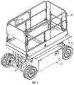
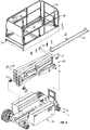
Figure 1 is a perspective view of an aerial work apparatus having a laterally offset work platform; -
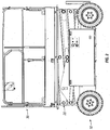
Figure 2 is a side elevation view of the apparatus shown inFig. 1 ; -
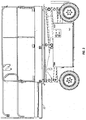
Figure 3 is a side elevation view of the apparatus ofFigs. 1 and2 showing an optional sliding platform deck in extended position; -
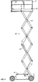
Figure 4 is a side elevation view of the apparatus showing the platform in an elevated position; -
Figure 5 is an end elevation view of the apparatus, partly broken away to show support of the platform on the lift mechanism; and -
Figure 6 is an exploded perspective view, partly broken away, showing various parts of the apparatus. - The apparatus shown in
Figs. 1 - 4 includes a chassis orbase 10, preferably in the form of a self propelledvehicle having wheels 12 or tracks, with a lift mechanism in the form of ascissors mechanism 20 which may be of any suitable conventional construction. Alternatively, other forms of lift mechanisms such as articulated or telescoping booms are contemplated. As best seen inFigs. 5 and6 , a typical scissors mechanism includes pivotally connected sets of left and rightside scissors arms 22 which are generally centrally positioned over and in alignment with the longitudinal centerline C/L C of thechassis 10. Thelowermost scissors arms 22 are connected at to afixed pivot 14 and to amoveable pivot 14 which is linearly moved toward and away from the fixed pivot by a drive arrangement in thescissors mechanism 20 to extend and retract the arms as is conventional. Aleveling link 24 is also shown inFig. 4 . - A
work platform 30 of generally rectangular configuration having adeck 32,guard rails 34 andsuitable controls 36 for use by an operator standing on the deck to elevate and position the work platform by driving thewheels 12 is also shown. The work platform has a longitudinally extending centerline C/L P shown inFig. 5 and is firmly attached to the top of the lift mechanism. - Unlike conventional apparatus, the
work platform 30 is attached to the top of thelift mechanism 20 in a laterally offset position such that the longitudinal centerline C/L P is spaced to the left of the longitudinal centerline C/L P as best seen inFig. 5 . When employing a scissors type lift mechanism as shown in the drawings, thework platform 30 may be conveniently supported at the upper end of thelift mechanism 20 through the use of spaced platform supports 26 pivotally connected to the tops of thescissors arms 22. Thesupports 26 includesliders 27 or rollers at the ends of thesupports 26 which are in turn guided in tracks provided by spaced parallel structural channels at the bottom of theplatform 30. The platform is thereby supported by contact of the lower surfaces of theupper flanges 28 of the channels with thesliders 27. Alternatively, if an articulated or telescopically extensible lift mechanism is employed, those skilled in the art will understand and readily devise suitable means as necessary to attach the platform in a laterally offset position relative to thelift mechanism 20. - A
sheet rack 38 for handling relatively narrow and heavy loads such as panes of glass is provided at one lateral side of the laterally offsetrectangular work platform 30. It will be noted that the outermost lateral edge of the sheet rack remains inside the vertically extended footprint of thechassis 10 including itswheels 12 such that the weight of theplatform 30 and load thereon is substantially balanced over thechassis 10 andlift mechanism 20 unlike conventional centrally positioned work platforms. - Use of a laterally
offset platform 30 to balance heavy loads such as panes of glass, also allows the most effective placement of counterweights on thechassis 10 thereby resulting in apparatus of lighter weight and lower cost. - An optional platform slide out
platform deck extension 33 may also be provided for improving the productivity of the work. - Those skilled in the art will understand that various modifications of the preferred embodiments shown and described herein can be made without departing from the scope of the invention which is defined by the appended claims.
Claims (4)
- An aerial work apparatus comprising:a) a mobile chassis (10) having a longitudinal centerline (C/L C) which extends in a first vertical plane;b) a scissors lift mechanism (20) aligned with said longitudinal centerline of said chassis and having an upper end and a lower end connected to said chassis; andc) a work platform (30) supported at said upper end of said lift mechanism,characterized in that said work platform having a longitudinal centerline (C/L P) which extends in a second vertical plane which is laterally spaced from and parallel to said first vertical plane whereby said work platform has a sheet rack (38) at one lateral side of said deck and that the outermost extent of said chassis (10) defines a first horizontal footprint and the outermost extent of said work platform and sheet rack (38) defines a second horizontal footprint, a vertical projection of said second footprint being entirely within the boundary of said first footprint.
- The aerial work apparatus of claim 1, characterized in that said work platform has a rectangular deck (32) and guardrails (34) at lateral sides of the deck equally spaced from said longitudinal centerline of said work platform.
- The aerial work apparatus of claim 1 or 2, characterized in that said platform includes a sliding deck extension (33) having guardrails.
- The aerial work apparatus of any one of the preceding claims, characterized in that said mobile chassis comprises a wheeled vehicle.
Applications Claiming Priority (2)
| Application Number | Priority Date | Filing Date | Title |
|---|---|---|---|
| US201161435020P | 2011-01-21 | 2011-01-21 | |
| US201161454544P | 2011-03-20 | 2011-03-20 |
Publications (2)
| Publication Number | Publication Date |
|---|---|
| EP2479135A1 EP2479135A1 (en) | 2012-07-25 |
| EP2479135B1 true EP2479135B1 (en) | 2016-05-11 |
Family
ID=45507588
Family Applications (1)
| Application Number | Title | Priority Date | Filing Date |
|---|---|---|---|
| EP12151876.5A Active EP2479135B1 (en) | 2011-01-21 | 2012-01-20 | Aerial work apparatus with laterally offset work platform |
Country Status (4)
| Country | Link |
|---|---|
| US (1) | US8678135B2 (en) |
| EP (1) | EP2479135B1 (en) |
| JP (1) | JP2012153534A (en) |
| CA (1) | CA2764836C (en) |
Cited By (3)
| Publication number | Priority date | Publication date | Assignee | Title |
|---|---|---|---|---|
| US11691858B2 (en) | 2019-03-15 | 2023-07-04 | Oshkosh Corporation | Scissor lift with offset pins |
| EP4438547A1 (en) | 2023-03-29 | 2024-10-02 | dieWertschöpfer GmbH | Mobile lifting work platform |
| US12252380B1 (en) | 2018-04-27 | 2025-03-18 | California Manufacturing & Engineering Company, Llc | Work platform having attached movable work step |
Families Citing this family (38)
| Publication number | Priority date | Publication date | Assignee | Title |
|---|---|---|---|---|
| FR2955571B1 (en) * | 2010-01-26 | 2012-04-27 | Haulotte Group | CONTROL PREPARER |
| CN102556897B (en) | 2011-12-14 | 2014-05-28 | 浙江中力机械有限公司 | Electric order picker |
| US9440830B2 (en) | 2011-12-14 | 2016-09-13 | Big Lift, Llc | Personnel lift vehicle |
| US9758360B2 (en) * | 2013-10-09 | 2017-09-12 | Billy D. Stanford | Apparatus for providing safety netting on manlifts |
| USD730614S1 (en) | 2013-11-26 | 2015-05-26 | Big Lift, Llc. | Personnel lift vehicle |
| US20210323401A1 (en) * | 2014-01-27 | 2021-10-21 | Xtreme Manufacturing, Llc | Method and system for a low height lift device |
| US10118810B2 (en) * | 2014-01-27 | 2018-11-06 | Xtreme Manufacturing, Llc | Method and system for a low height lift device |
| CA2944316C (en) * | 2015-10-07 | 2023-12-19 | Charles Frederick Harmon | Cage assembly for use with pivotal gangway |
| CA2924982C (en) * | 2016-03-24 | 2023-09-19 | Adam Toma | Mobile well servicing units and related methods |
| CN205575519U (en) * | 2016-03-29 | 2016-09-14 | 石东风 | Novel scissors formula high altitude construction car |
| US10167181B2 (en) * | 2016-07-22 | 2019-01-01 | Chejiang Dingli Machinery Co., Ltd. | Hydraulic steering shear-fork type aerial work platform |
| CN105967120A (en) * | 2016-07-26 | 2016-09-28 | 钦州学院 | Lifting platform car capable of moving in four directions |
| CN105967121A (en) * | 2016-07-26 | 2016-09-28 | 钦州学院 | Scissor-type lifting device capable of adjusting height flexibly |
| CN105967119A (en) * | 2016-07-26 | 2016-09-28 | 钦州学院 | Lifting platform car capable of flexibly regulating height and moving |
| AU2016101598B4 (en) * | 2016-09-09 | 2018-02-15 | Viljevac, Miroslav MR | Device and Method for Accessing a Racking System |
| US9855879B1 (en) | 2016-10-05 | 2018-01-02 | Extendquip, Llc | Support assembly for mounting an accessory to a work utility vehicle |
| US10467932B1 (en) | 2017-04-06 | 2019-11-05 | Kooima Company | Mobile elevating apparatus |
| US10991279B1 (en) | 2017-04-06 | 2021-04-27 | Kooima Ag, Inc. | Mobile elevating apparatus |
| USD859773S1 (en) * | 2017-07-13 | 2019-09-10 | Jcb Access Limited | Scissor lift |
| USD856623S1 (en) * | 2017-07-13 | 2019-08-13 | Jcb Access Limited | Scissor lift |
| USD858025S1 (en) * | 2017-07-13 | 2019-08-27 | Jcb Access Limited | Controller cradle |
| CN107500204A (en) * | 2017-07-22 | 2017-12-22 | 合肥亚美科技股份有限公司 | A kind of aerial work platform load carrier |
| IL315105A (en) * | 2017-09-20 | 2024-10-01 | Look Dynamics Inc | Photonic neural network system |
| US10858893B2 (en) | 2018-02-02 | 2020-12-08 | Adam Toma | Laterally movable mobile well servicing units and methods of use |
| US11112060B2 (en) * | 2018-04-05 | 2021-09-07 | California Manufacturing & Engineering Co Llc | Mobile work machine with fluid drip retention |
| US20190330034A1 (en) * | 2018-04-27 | 2019-10-31 | California Manufacturing & Engineering Company, Llc | Work platform with extension deck and work step |
| CN109057296B (en) * | 2018-08-14 | 2020-08-25 | 安徽凯迪建业有限公司 | Lifting platform capable of storing building garbage for building construction |
| MX2021007206A (en) | 2018-12-17 | 2021-12-15 | Terex South Dakota Inc | Access deck assembly and handle assembly for an aerial work platform of a vehicle. |
| AU2020254332B2 (en) * | 2019-04-05 | 2024-06-20 | Oshkosh Corporation | Scissor lift descent control systems and methods |
| US11162267B1 (en) * | 2019-04-26 | 2021-11-02 | Patrick J. Santini | Adjustable telescoping plank |
| CN110987296A (en) * | 2019-12-20 | 2020-04-10 | 中联重科股份有限公司 | Balance control method and system for aerial work platform, and aerial work platform |
| CN112125246A (en) * | 2020-09-07 | 2020-12-25 | 国网江苏省电力有限公司滨海县供电分公司 | A high-altitude transfer platform and a lifting device |
| KR102418197B1 (en) * | 2020-09-25 | 2022-07-07 | 주식회사 원방테크 | Lifting apparatus for system ceiling and method for installing system ceiling module |
| CN112746733A (en) * | 2020-12-14 | 2021-05-04 | 衢州学院 | High-altitude electric power construction operation platform |
| US12528686B2 (en) * | 2021-05-18 | 2026-01-20 | Innovatech Systems, Llc | Vehicle apparatus with an elevatable platform used for building a structure |
| CN114715300B (en) * | 2022-04-26 | 2023-01-24 | 无锡职业技术学院 | A crawler electric vehicle for sandy ground operation |
| CN115321444B (en) * | 2022-08-30 | 2023-06-30 | 江苏徐工国重实验室科技有限公司 | Work Platforms and Aerial Work Vehicles |
| CN117287019B (en) * | 2023-11-27 | 2024-03-01 | 山东华宝环保新材料有限公司 | Scaffold for building |
Citations (1)
| Publication number | Priority date | Publication date | Assignee | Title |
|---|---|---|---|---|
| EP1396468A1 (en) * | 2002-09-09 | 2004-03-10 | JLG Industries, Inc. | Platform load sensing for vertical lifts |
Family Cites Families (10)
| Publication number | Priority date | Publication date | Assignee | Title |
|---|---|---|---|---|
| US3509965A (en) | 1968-09-13 | 1970-05-05 | Maurice E Mitchell | Mobile overhead service unit |
| US3638757A (en) * | 1970-05-22 | 1972-02-01 | Ralph D Sampson | Mobile elevating scaffolds |
| GB1504969A (en) | 1976-02-27 | 1978-03-22 | Simon Eng Dudley Ltd | Access equipment |
| FR2703673B1 (en) | 1993-04-08 | 1995-07-13 | Duarib Ets | NACELLE ELEVATOR DEVICE. |
| DE4316663A1 (en) | 1993-05-11 | 1994-11-17 | Reichsbahn Werk Fuer Gleisbaum | Inspection and / or repair vehicle |
| US5381872A (en) * | 1994-04-04 | 1995-01-17 | Peruzzi; Victor M. | Scaffold system |
| CA2177508C (en) * | 1996-05-28 | 2001-03-20 | George Leslie Lawson | Mobile lift assembly |
| CA2440788C (en) | 2003-09-12 | 2012-01-03 | Jean-Paul Fredette | Motorized scaffold with displaceable worker support platform |
| US20080105498A1 (en) * | 2006-06-12 | 2008-05-08 | Genie Industries, Inc. | Joint assembly and related methods |
| JP2011032083A (en) | 2009-08-05 | 2011-02-17 | Toyota T & S Kensetsu Kk | Loading fitting for high-lift working vehicle |
-
2012
- 2012-01-05 US US13/344,526 patent/US8678135B2/en active Active
- 2012-01-19 JP JP2012009357A patent/JP2012153534A/en active Pending
- 2012-01-20 CA CA2764836A patent/CA2764836C/en active Active
- 2012-01-20 EP EP12151876.5A patent/EP2479135B1/en active Active
Patent Citations (1)
| Publication number | Priority date | Publication date | Assignee | Title |
|---|---|---|---|---|
| EP1396468A1 (en) * | 2002-09-09 | 2004-03-10 | JLG Industries, Inc. | Platform load sensing for vertical lifts |
Cited By (4)
| Publication number | Priority date | Publication date | Assignee | Title |
|---|---|---|---|---|
| US12252380B1 (en) | 2018-04-27 | 2025-03-18 | California Manufacturing & Engineering Company, Llc | Work platform having attached movable work step |
| US11691858B2 (en) | 2019-03-15 | 2023-07-04 | Oshkosh Corporation | Scissor lift with offset pins |
| US12151920B2 (en) | 2019-03-15 | 2024-11-26 | Oshkosh Corporation | Scissor lift with offset pins |
| EP4438547A1 (en) | 2023-03-29 | 2024-10-02 | dieWertschöpfer GmbH | Mobile lifting work platform |
Also Published As
| Publication number | Publication date |
|---|---|
| EP2479135A1 (en) | 2012-07-25 |
| JP2012153534A (en) | 2012-08-16 |
| CA2764836A1 (en) | 2012-07-21 |
| US20120186908A1 (en) | 2012-07-26 |
| US8678135B2 (en) | 2014-03-25 |
| CA2764836C (en) | 2017-03-14 |
Similar Documents
| Publication | Publication Date | Title |
|---|---|---|
| CA2764836C (en) | Aerial work apparatus with laterally offset work platform | |
| AU2004203582B2 (en) | Mast construction for a lift truck | |
| US4867277A (en) | Portable lifting device and cart | |
| EP3560887B1 (en) | Work platform with extension deck and work step | |
| US8127919B2 (en) | Scissors lift guard for a sheet material conveyor | |
| CA2699556A1 (en) | Mobile elevating work platform | |
| US20170044782A1 (en) | A device for lifting and transporting sheet material | |
| FI127507B (en) | PERSONAL LIFT | |
| KR20140003277U (en) | A lift for a high place work | |
| EP2818381B1 (en) | Trolley for the transportation of a load on staircases | |
| KR101400209B1 (en) | Foldable bucket for crane | |
| EP3031769B1 (en) | Vehicle comprising scissor stabilisers | |
| US20070261917A1 (en) | Foldable work platform | |
| US20230382444A1 (en) | Drywall cart and methods of using the same | |
| KR20190111201A (en) | Work stepladder with elevating caster | |
| US20160200556A1 (en) | Crane and support unit for such a crane | |
| US20240300792A1 (en) | Work platform with extension deck and work step, and related methods | |
| CN102828629B (en) | working platform device | |
| US20130020541A1 (en) | Vehicle Lift | |
| CN214527891U (en) | Sliding plate type double-layer lifting platform for automobile assembly | |
| EP4093927B1 (en) | Improved adjustable stairway | |
| EP1775255B1 (en) | An extensible hoist platform | |
| US20080230312A1 (en) | Vehicle Supported, Portable Scaffold System | |
| CN120717387A (en) | Access deck components for vehicle aerial work platforms | |
| WO2023056187A1 (en) | Lift and guard |
Legal Events
| Date | Code | Title | Description |
|---|---|---|---|
| PUAI | Public reference made under article 153(3) epc to a published international application that has entered the european phase |
Free format text: ORIGINAL CODE: 0009012 |
|
| AK | Designated contracting states |
Kind code of ref document: A1 Designated state(s): AL AT BE BG CH CY CZ DE DK EE ES FI FR GB GR HR HU IE IS IT LI LT LU LV MC MK MT NL NO PL PT RO RS SE SI SK SM TR |
|
| AX | Request for extension of the european patent |
Extension state: BA ME |
|
| 17P | Request for examination filed |
Effective date: 20130118 |
|
| 17Q | First examination report despatched |
Effective date: 20140401 |
|
| REG | Reference to a national code |
Ref country code: DE Ref legal event code: R079 Ref document number: 602012018235 Country of ref document: DE Free format text: PREVIOUS MAIN CLASS: B66F0011040000 Ipc: E04G0001150000 |
|
| GRAP | Despatch of communication of intention to grant a patent |
Free format text: ORIGINAL CODE: EPIDOSNIGR1 |
|
| RIC1 | Information provided on ipc code assigned before grant |
Ipc: E04G 1/22 20060101ALI20151030BHEP Ipc: E04G 1/15 20060101AFI20151030BHEP Ipc: B66F 11/04 20060101ALI20151030BHEP |
|
| INTG | Intention to grant announced |
Effective date: 20151127 |
|
| GRAS | Grant fee paid |
Free format text: ORIGINAL CODE: EPIDOSNIGR3 |
|
| GRAA | (expected) grant |
Free format text: ORIGINAL CODE: 0009210 |
|
| AK | Designated contracting states |
Kind code of ref document: B1 Designated state(s): AL AT BE BG CH CY CZ DE DK EE ES FI FR GB GR HR HU IE IS IT LI LT LU LV MC MK MT NL NO PL PT RO RS SE SI SK SM TR |
|
| REG | Reference to a national code |
Ref country code: GB Ref legal event code: FG4D |
|
| REG | Reference to a national code |
Ref country code: CH Ref legal event code: EP |
|
| REG | Reference to a national code |
Ref country code: AT Ref legal event code: REF Ref document number: 798812 Country of ref document: AT Kind code of ref document: T Effective date: 20160515 |
|
| REG | Reference to a national code |
Ref country code: IE Ref legal event code: FG4D |
|
| REG | Reference to a national code |
Ref country code: DE Ref legal event code: R096 Ref document number: 602012018235 Country of ref document: DE |
|
| REG | Reference to a national code |
Ref country code: SE Ref legal event code: TRGR |
|
| REG | Reference to a national code |
Ref country code: LT Ref legal event code: MG4D |
|
| REG | Reference to a national code |
Ref country code: NL Ref legal event code: MP Effective date: 20160511 |
|
| PG25 | Lapsed in a contracting state [announced via postgrant information from national office to epo] |
Ref country code: FI Free format text: LAPSE BECAUSE OF FAILURE TO SUBMIT A TRANSLATION OF THE DESCRIPTION OR TO PAY THE FEE WITHIN THE PRESCRIBED TIME-LIMIT Effective date: 20160511 Ref country code: LT Free format text: LAPSE BECAUSE OF FAILURE TO SUBMIT A TRANSLATION OF THE DESCRIPTION OR TO PAY THE FEE WITHIN THE PRESCRIBED TIME-LIMIT Effective date: 20160511 Ref country code: NL Free format text: LAPSE BECAUSE OF FAILURE TO SUBMIT A TRANSLATION OF THE DESCRIPTION OR TO PAY THE FEE WITHIN THE PRESCRIBED TIME-LIMIT Effective date: 20160511 Ref country code: NO Free format text: LAPSE BECAUSE OF FAILURE TO SUBMIT A TRANSLATION OF THE DESCRIPTION OR TO PAY THE FEE WITHIN THE PRESCRIBED TIME-LIMIT Effective date: 20160811 |
|
| REG | Reference to a national code |
Ref country code: AT Ref legal event code: MK05 Ref document number: 798812 Country of ref document: AT Kind code of ref document: T Effective date: 20160511 |
|
| PG25 | Lapsed in a contracting state [announced via postgrant information from national office to epo] |
Ref country code: RS Free format text: LAPSE BECAUSE OF FAILURE TO SUBMIT A TRANSLATION OF THE DESCRIPTION OR TO PAY THE FEE WITHIN THE PRESCRIBED TIME-LIMIT Effective date: 20160511 Ref country code: ES Free format text: LAPSE BECAUSE OF FAILURE TO SUBMIT A TRANSLATION OF THE DESCRIPTION OR TO PAY THE FEE WITHIN THE PRESCRIBED TIME-LIMIT Effective date: 20160511 Ref country code: PT Free format text: LAPSE BECAUSE OF FAILURE TO SUBMIT A TRANSLATION OF THE DESCRIPTION OR TO PAY THE FEE WITHIN THE PRESCRIBED TIME-LIMIT Effective date: 20160912 Ref country code: GR Free format text: LAPSE BECAUSE OF FAILURE TO SUBMIT A TRANSLATION OF THE DESCRIPTION OR TO PAY THE FEE WITHIN THE PRESCRIBED TIME-LIMIT Effective date: 20160812 Ref country code: HR Free format text: LAPSE BECAUSE OF FAILURE TO SUBMIT A TRANSLATION OF THE DESCRIPTION OR TO PAY THE FEE WITHIN THE PRESCRIBED TIME-LIMIT Effective date: 20160511 Ref country code: LV Free format text: LAPSE BECAUSE OF FAILURE TO SUBMIT A TRANSLATION OF THE DESCRIPTION OR TO PAY THE FEE WITHIN THE PRESCRIBED TIME-LIMIT Effective date: 20160511 |
|
| PG25 | Lapsed in a contracting state [announced via postgrant information from national office to epo] |
Ref country code: IT Free format text: LAPSE BECAUSE OF FAILURE TO SUBMIT A TRANSLATION OF THE DESCRIPTION OR TO PAY THE FEE WITHIN THE PRESCRIBED TIME-LIMIT Effective date: 20160511 |
|
| REG | Reference to a national code |
Ref country code: FR Ref legal event code: PLFP Year of fee payment: 6 |
|
| PG25 | Lapsed in a contracting state [announced via postgrant information from national office to epo] |
Ref country code: CZ Free format text: LAPSE BECAUSE OF FAILURE TO SUBMIT A TRANSLATION OF THE DESCRIPTION OR TO PAY THE FEE WITHIN THE PRESCRIBED TIME-LIMIT Effective date: 20160511 Ref country code: DK Free format text: LAPSE BECAUSE OF FAILURE TO SUBMIT A TRANSLATION OF THE DESCRIPTION OR TO PAY THE FEE WITHIN THE PRESCRIBED TIME-LIMIT Effective date: 20160511 Ref country code: RO Free format text: LAPSE BECAUSE OF FAILURE TO SUBMIT A TRANSLATION OF THE DESCRIPTION OR TO PAY THE FEE WITHIN THE PRESCRIBED TIME-LIMIT Effective date: 20160511 Ref country code: EE Free format text: LAPSE BECAUSE OF FAILURE TO SUBMIT A TRANSLATION OF THE DESCRIPTION OR TO PAY THE FEE WITHIN THE PRESCRIBED TIME-LIMIT Effective date: 20160511 Ref country code: SK Free format text: LAPSE BECAUSE OF FAILURE TO SUBMIT A TRANSLATION OF THE DESCRIPTION OR TO PAY THE FEE WITHIN THE PRESCRIBED TIME-LIMIT Effective date: 20160511 |
|
| REG | Reference to a national code |
Ref country code: DE Ref legal event code: R097 Ref document number: 602012018235 Country of ref document: DE |
|
| PG25 | Lapsed in a contracting state [announced via postgrant information from national office to epo] |
Ref country code: SM Free format text: LAPSE BECAUSE OF FAILURE TO SUBMIT A TRANSLATION OF THE DESCRIPTION OR TO PAY THE FEE WITHIN THE PRESCRIBED TIME-LIMIT Effective date: 20160511 Ref country code: BE Free format text: LAPSE BECAUSE OF FAILURE TO SUBMIT A TRANSLATION OF THE DESCRIPTION OR TO PAY THE FEE WITHIN THE PRESCRIBED TIME-LIMIT Effective date: 20160511 Ref country code: AT Free format text: LAPSE BECAUSE OF FAILURE TO SUBMIT A TRANSLATION OF THE DESCRIPTION OR TO PAY THE FEE WITHIN THE PRESCRIBED TIME-LIMIT Effective date: 20160511 Ref country code: PL Free format text: LAPSE BECAUSE OF FAILURE TO SUBMIT A TRANSLATION OF THE DESCRIPTION OR TO PAY THE FEE WITHIN THE PRESCRIBED TIME-LIMIT Effective date: 20160511 |
|
| PLBE | No opposition filed within time limit |
Free format text: ORIGINAL CODE: 0009261 |
|
| STAA | Information on the status of an ep patent application or granted ep patent |
Free format text: STATUS: NO OPPOSITION FILED WITHIN TIME LIMIT |
|
| 26N | No opposition filed |
Effective date: 20170214 |
|
| PG25 | Lapsed in a contracting state [announced via postgrant information from national office to epo] |
Ref country code: SI Free format text: LAPSE BECAUSE OF FAILURE TO SUBMIT A TRANSLATION OF THE DESCRIPTION OR TO PAY THE FEE WITHIN THE PRESCRIBED TIME-LIMIT Effective date: 20160511 |
|
| REG | Reference to a national code |
Ref country code: CH Ref legal event code: PL |
|
| PG25 | Lapsed in a contracting state [announced via postgrant information from national office to epo] |
Ref country code: MC Free format text: LAPSE BECAUSE OF FAILURE TO SUBMIT A TRANSLATION OF THE DESCRIPTION OR TO PAY THE FEE WITHIN THE PRESCRIBED TIME-LIMIT Effective date: 20160511 |
|
| PG25 | Lapsed in a contracting state [announced via postgrant information from national office to epo] |
Ref country code: CH Free format text: LAPSE BECAUSE OF NON-PAYMENT OF DUE FEES Effective date: 20170131 Ref country code: LI Free format text: LAPSE BECAUSE OF NON-PAYMENT OF DUE FEES Effective date: 20170131 |
|
| REG | Reference to a national code |
Ref country code: IE Ref legal event code: MM4A |
|
| PG25 | Lapsed in a contracting state [announced via postgrant information from national office to epo] |
Ref country code: LU Free format text: LAPSE BECAUSE OF NON-PAYMENT OF DUE FEES Effective date: 20170120 |
|
| REG | Reference to a national code |
Ref country code: FR Ref legal event code: PLFP Year of fee payment: 7 |
|
| PG25 | Lapsed in a contracting state [announced via postgrant information from national office to epo] |
Ref country code: IE Free format text: LAPSE BECAUSE OF NON-PAYMENT OF DUE FEES Effective date: 20170120 |
|
| PG25 | Lapsed in a contracting state [announced via postgrant information from national office to epo] |
Ref country code: MT Free format text: LAPSE BECAUSE OF NON-PAYMENT OF DUE FEES Effective date: 20170120 |
|
| PG25 | Lapsed in a contracting state [announced via postgrant information from national office to epo] |
Ref country code: AL Free format text: LAPSE BECAUSE OF FAILURE TO SUBMIT A TRANSLATION OF THE DESCRIPTION OR TO PAY THE FEE WITHIN THE PRESCRIBED TIME-LIMIT Effective date: 20160511 |
|
| PGFP | Annual fee paid to national office [announced via postgrant information from national office to epo] |
Ref country code: FR Payment date: 20190116 Year of fee payment: 8 Ref country code: DE Payment date: 20190123 Year of fee payment: 8 |
|
| PGFP | Annual fee paid to national office [announced via postgrant information from national office to epo] |
Ref country code: SE Payment date: 20190116 Year of fee payment: 8 |
|
| PG25 | Lapsed in a contracting state [announced via postgrant information from national office to epo] |
Ref country code: HU Free format text: LAPSE BECAUSE OF FAILURE TO SUBMIT A TRANSLATION OF THE DESCRIPTION OR TO PAY THE FEE WITHIN THE PRESCRIBED TIME-LIMIT; INVALID AB INITIO Effective date: 20120120 |
|
| PG25 | Lapsed in a contracting state [announced via postgrant information from national office to epo] |
Ref country code: BG Free format text: LAPSE BECAUSE OF FAILURE TO SUBMIT A TRANSLATION OF THE DESCRIPTION OR TO PAY THE FEE WITHIN THE PRESCRIBED TIME-LIMIT Effective date: 20160511 |
|
| PG25 | Lapsed in a contracting state [announced via postgrant information from national office to epo] |
Ref country code: CY Free format text: LAPSE BECAUSE OF NON-PAYMENT OF DUE FEES Effective date: 20160511 |
|
| PG25 | Lapsed in a contracting state [announced via postgrant information from national office to epo] |
Ref country code: MK Free format text: LAPSE BECAUSE OF FAILURE TO SUBMIT A TRANSLATION OF THE DESCRIPTION OR TO PAY THE FEE WITHIN THE PRESCRIBED TIME-LIMIT Effective date: 20160511 |
|
| PG25 | Lapsed in a contracting state [announced via postgrant information from national office to epo] |
Ref country code: TR Free format text: LAPSE BECAUSE OF FAILURE TO SUBMIT A TRANSLATION OF THE DESCRIPTION OR TO PAY THE FEE WITHIN THE PRESCRIBED TIME-LIMIT Effective date: 20160511 |
|
| PG25 | Lapsed in a contracting state [announced via postgrant information from national office to epo] |
Ref country code: IS Free format text: LAPSE BECAUSE OF FAILURE TO SUBMIT A TRANSLATION OF THE DESCRIPTION OR TO PAY THE FEE WITHIN THE PRESCRIBED TIME-LIMIT Effective date: 20160911 |
|
| REG | Reference to a national code |
Ref country code: DE Ref legal event code: R119 Ref document number: 602012018235 Country of ref document: DE |
|
| REG | Reference to a national code |
Ref country code: SE Ref legal event code: EUG |
|
| REG | Reference to a national code |
Ref country code: SE Ref legal event code: EUG |
|
| PG25 | Lapsed in a contracting state [announced via postgrant information from national office to epo] |
Ref country code: SE Free format text: LAPSE BECAUSE OF NON-PAYMENT OF DUE FEES Effective date: 20200121 Ref country code: DE Free format text: LAPSE BECAUSE OF NON-PAYMENT OF DUE FEES Effective date: 20200801 Ref country code: FR Free format text: LAPSE BECAUSE OF NON-PAYMENT OF DUE FEES Effective date: 20200131 |
|
| PGFP | Annual fee paid to national office [announced via postgrant information from national office to epo] |
Ref country code: GB Payment date: 20260102 Year of fee payment: 15 |