EP2479043A1 - Wheel rolling bearing device - Google Patents
Wheel rolling bearing device Download PDFInfo
- Publication number
- EP2479043A1 EP2479043A1 EP12151247A EP12151247A EP2479043A1 EP 2479043 A1 EP2479043 A1 EP 2479043A1 EP 12151247 A EP12151247 A EP 12151247A EP 12151247 A EP12151247 A EP 12151247A EP 2479043 A1 EP2479043 A1 EP 2479043A1
- Authority
- EP
- European Patent Office
- Prior art keywords
- outer ring
- raceway
- ring raceway
- raceway surface
- shoulder
- Prior art date
- Legal status (The legal status is an assumption and is not a legal conclusion. Google has not performed a legal analysis and makes no representation as to the accuracy of the status listed.)
- Granted
Links
- 238000005096 rolling process Methods 0.000 title claims abstract description 17
- 230000002093 peripheral effect Effects 0.000 claims description 18
- 238000005242 forging Methods 0.000 claims description 11
- 238000005422 blasting Methods 0.000 claims description 5
- 239000013585 weight reducing agent Substances 0.000 description 7
- 230000004323 axial length Effects 0.000 description 2
- 238000000034 method Methods 0.000 description 2
- 230000000717 retained effect Effects 0.000 description 2
- 239000000725 suspension Substances 0.000 description 2
- 238000004519 manufacturing process Methods 0.000 description 1
- 239000000463 material Substances 0.000 description 1
- 230000036316 preload Effects 0.000 description 1
- 230000001737 promoting effect Effects 0.000 description 1
Images


Classifications
-
- B—PERFORMING OPERATIONS; TRANSPORTING
- B60—VEHICLES IN GENERAL
- B60B—VEHICLE WHEELS; CASTORS; AXLES FOR WHEELS OR CASTORS; INCREASING WHEEL ADHESION
- B60B27/00—Hubs
- B60B27/0005—Hubs with ball bearings
-
- B—PERFORMING OPERATIONS; TRANSPORTING
- B60—VEHICLES IN GENERAL
- B60B—VEHICLE WHEELS; CASTORS; AXLES FOR WHEELS OR CASTORS; INCREASING WHEEL ADHESION
- B60B27/00—Hubs
- B60B27/0094—Hubs one or more of the bearing races are formed by the hub
-
- F—MECHANICAL ENGINEERING; LIGHTING; HEATING; WEAPONS; BLASTING
- F16—ENGINEERING ELEMENTS AND UNITS; GENERAL MEASURES FOR PRODUCING AND MAINTAINING EFFECTIVE FUNCTIONING OF MACHINES OR INSTALLATIONS; THERMAL INSULATION IN GENERAL
- F16C—SHAFTS; FLEXIBLE SHAFTS; ELEMENTS OR CRANKSHAFT MECHANISMS; ROTARY BODIES OTHER THAN GEARING ELEMENTS; BEARINGS
- F16C19/00—Bearings with rolling contact, for exclusively rotary movement
- F16C19/02—Bearings with rolling contact, for exclusively rotary movement with bearing balls essentially of the same size in one or more circular rows
- F16C19/14—Bearings with rolling contact, for exclusively rotary movement with bearing balls essentially of the same size in one or more circular rows for both radial and axial load
- F16C19/18—Bearings with rolling contact, for exclusively rotary movement with bearing balls essentially of the same size in one or more circular rows for both radial and axial load with two or more rows of balls
- F16C19/181—Bearings with rolling contact, for exclusively rotary movement with bearing balls essentially of the same size in one or more circular rows for both radial and axial load with two or more rows of balls with angular contact
- F16C19/183—Bearings with rolling contact, for exclusively rotary movement with bearing balls essentially of the same size in one or more circular rows for both radial and axial load with two or more rows of balls with angular contact with two rows at opposite angles
- F16C19/184—Bearings with rolling contact, for exclusively rotary movement with bearing balls essentially of the same size in one or more circular rows for both radial and axial load with two or more rows of balls with angular contact with two rows at opposite angles in O-arrangement
- F16C19/186—Bearings with rolling contact, for exclusively rotary movement with bearing balls essentially of the same size in one or more circular rows for both radial and axial load with two or more rows of balls with angular contact with two rows at opposite angles in O-arrangement with three raceways provided integrally on parts other than race rings, e.g. third generation hubs
-
- F—MECHANICAL ENGINEERING; LIGHTING; HEATING; WEAPONS; BLASTING
- F16—ENGINEERING ELEMENTS AND UNITS; GENERAL MEASURES FOR PRODUCING AND MAINTAINING EFFECTIVE FUNCTIONING OF MACHINES OR INSTALLATIONS; THERMAL INSULATION IN GENERAL
- F16C—SHAFTS; FLEXIBLE SHAFTS; ELEMENTS OR CRANKSHAFT MECHANISMS; ROTARY BODIES OTHER THAN GEARING ELEMENTS; BEARINGS
- F16C33/00—Parts of bearings; Special methods for making bearings or parts thereof
- F16C33/30—Parts of ball or roller bearings
- F16C33/58—Raceways; Race rings
- F16C33/583—Details of specific parts of races
- F16C33/585—Details of specific parts of races of raceways, e.g. ribs to guide the rollers
-
- B—PERFORMING OPERATIONS; TRANSPORTING
- B60—VEHICLES IN GENERAL
- B60B—VEHICLE WHEELS; CASTORS; AXLES FOR WHEELS OR CASTORS; INCREASING WHEEL ADHESION
- B60B2380/00—Bearings
- B60B2380/70—Arrangements
- B60B2380/76—Twin or multiple bearings having different diameters
-
- B—PERFORMING OPERATIONS; TRANSPORTING
- B60—VEHICLES IN GENERAL
- B60Y—INDEXING SCHEME RELATING TO ASPECTS CROSS-CUTTING VEHICLE TECHNOLOGY
- B60Y2200/00—Type of vehicle
- B60Y2200/10—Road Vehicles
- B60Y2200/11—Passenger cars; Automobiles
-
- F—MECHANICAL ENGINEERING; LIGHTING; HEATING; WEAPONS; BLASTING
- F16—ENGINEERING ELEMENTS AND UNITS; GENERAL MEASURES FOR PRODUCING AND MAINTAINING EFFECTIVE FUNCTIONING OF MACHINES OR INSTALLATIONS; THERMAL INSULATION IN GENERAL
- F16C—SHAFTS; FLEXIBLE SHAFTS; ELEMENTS OR CRANKSHAFT MECHANISMS; ROTARY BODIES OTHER THAN GEARING ELEMENTS; BEARINGS
- F16C2240/00—Specified values or numerical ranges of parameters; Relations between them
- F16C2240/30—Angles, e.g. inclinations
-
- F—MECHANICAL ENGINEERING; LIGHTING; HEATING; WEAPONS; BLASTING
- F16—ENGINEERING ELEMENTS AND UNITS; GENERAL MEASURES FOR PRODUCING AND MAINTAINING EFFECTIVE FUNCTIONING OF MACHINES OR INSTALLATIONS; THERMAL INSULATION IN GENERAL
- F16C—SHAFTS; FLEXIBLE SHAFTS; ELEMENTS OR CRANKSHAFT MECHANISMS; ROTARY BODIES OTHER THAN GEARING ELEMENTS; BEARINGS
- F16C2240/00—Specified values or numerical ranges of parameters; Relations between them
- F16C2240/40—Linear dimensions, e.g. length, radius, thickness, gap
- F16C2240/70—Diameters; Radii
- F16C2240/80—Pitch circle diameters [PCD]
-
- F—MECHANICAL ENGINEERING; LIGHTING; HEATING; WEAPONS; BLASTING
- F16—ENGINEERING ELEMENTS AND UNITS; GENERAL MEASURES FOR PRODUCING AND MAINTAINING EFFECTIVE FUNCTIONING OF MACHINES OR INSTALLATIONS; THERMAL INSULATION IN GENERAL
- F16C—SHAFTS; FLEXIBLE SHAFTS; ELEMENTS OR CRANKSHAFT MECHANISMS; ROTARY BODIES OTHER THAN GEARING ELEMENTS; BEARINGS
- F16C2326/00—Articles relating to transporting
- F16C2326/01—Parts of vehicles in general
- F16C2326/02—Wheel hubs or castors
-
- Y—GENERAL TAGGING OF NEW TECHNOLOGICAL DEVELOPMENTS; GENERAL TAGGING OF CROSS-SECTIONAL TECHNOLOGIES SPANNING OVER SEVERAL SECTIONS OF THE IPC; TECHNICAL SUBJECTS COVERED BY FORMER USPC CROSS-REFERENCE ART COLLECTIONS [XRACs] AND DIGESTS
- Y02—TECHNOLOGIES OR APPLICATIONS FOR MITIGATION OR ADAPTATION AGAINST CLIMATE CHANGE
- Y02T—CLIMATE CHANGE MITIGATION TECHNOLOGIES RELATED TO TRANSPORTATION
- Y02T10/00—Road transport of goods or passengers
- Y02T10/80—Technologies aiming to reduce greenhouse gasses emissions common to all road transportation technologies
- Y02T10/86—Optimisation of rolling resistance, e.g. weight reduction
Landscapes
- Engineering & Computer Science (AREA)
- General Engineering & Computer Science (AREA)
- Mechanical Engineering (AREA)
- Rolling Contact Bearings (AREA)
Abstract
Description
- The invention relates to a wheel rolling bearing device.
- In a wheel rolling bearing device (also referred to as "wheel hub unit"), an inner-side inner ring raceway surface and an outer-side inner ring raceway surface are formed at a predetermined axial interval on the outer peripheral surface of a hub spindle of a hub wheel to which a wheel is fitted. An inner-side outer ring raceway surface and an outer-side outer ring raceway surface are formed at a predetermined axial interval on the inner peripheral surface of an outer ring member arranged on the outer periphery of the hub spindle. Inner-row balls are rollably arranged between the inner-side inner ring raceway surface of the hub spindle and the inner-side outer ring raceway surface of the outer ring member, and outer-row balls are rollably arranged between the outer-side inner ring raceway surface of the hub spindle and the outer-side outer ring raceway surface of the outer ring member. In the thus configured wheel rolling bearing device, a pitch diameter of the inner-row ball set and a pitch diameter of the outer-row ball set each are increased to increase the number of the inner-row balls and the number of the outer-row balls to thereby make it possible to achieve high stiffness. However, if the pitch diameter of the inner-row ball set and the pitch diameter of the outer-row ball set each are increased, the size of the outer ring member also increases. As a result, the weight of the outer ring member increases. In addition, if the size of the outer ring member increases, the outside diameter of a fitting shaft portion of the outer ring member may be excessively large with respect to an assembling hole of a vehicle body-side member, such as a knuckle and a carrier, of a suspension of a vehicle. As a result, it may be impossible to fit the fitting shaft portion into the assembling hole. For this reason, there is known the following technique. According to the technique, in order to achieve weight reduction and high stiffness while maintaining the outside diameter of the fitting shaft portion of the outer ring member at such a diameter that the fitting shaft portion is able to be fitted into the assembling hole of the vehicle body-side member, the pitch diameter of the outer-row ball set is set to be larger than the pitch diameter of the inner-row ball set. Thus, the number of the outer-row balls is larger than the number of the inner-row balls (for example, see Japanese Patent Application Publication No.
2004-108449 JP-A-2004-108449 - If the pitch diameter of the outer-row ball set is set to be larger than the pitch diameter of the inner-row ball set to make the number of the outer-row balls larger than the number of the inner-row balls, weight reduction and stiffness increase are promoted effectively. However, if the pitch diameter of the outer-row ball set is increased, the outer-row balls tend to easily run on the outer-side raceway shoulder when a load during rotation of the bearing is applied to the outer-row balls. When the outer-row balls run on the outer-side raceway shoulder, edge stress occurs at a boundary edge portion between the outer-side outer ring raceway surface and the outer-side raceway shoulder. As a result, the bearing service life may be shortened.
- It is an object of the invention to provide a wheel rolling bearing device with which it is possible to prevent outer-row balls from running on an outer-side raceway shoulder while promoting weight reduction and stiffness increase.
- An aspect of the invention relates to a wheel rolling bearing device described as follows. An inner-side inner ring raceway surface and an outer-side inner ring raceway surface are formed at a predetermined interval in an axial direction on an outer peripheral surface of a hub spindle of a hub wheel to which a wheel is connected. An inner-side outer ring raceway surface and an outer-side outer ring raceway surface are formed at a predetermined interval in the axial direction on an inner peripheral surface of an outer ring member arranged on an outer periphery of the hub spindle. Inner-row balls are rollably arranged between the inner-side inner ring raceway surface and the inner-side outer ring raceway surface. Outer-row balls are rollably arranged between the outer-side inner ring raceway surface and the outer-side outer ring raceway surface. Where a pitch diameter of the inner-row ball set is D1 and a pitch diameter of the outer-row ball set is D2, D and D2 are set so as to satisfy the relationship "D1< D2". Where an angle of a raceway circular arc from an intersection point of each inner-row ball with the inner-side outer ring raceway surface at a contact angle to a boundary portion of an inner-side raceway shoulder is θ1 and an angle of a raceway circular arc from an intersection point of each outer-row ball with the outer-side outer ring raceway surface at a contact angle to a boundary portion of an outer-side raceway shoulder is θ2, θ1 and θ2 are set so as to satisfy the relationship "θ1 < θ2".
- Features, advantages, and technical and industrial significance of exemplary embodiments of the invention will be described below with reference to the accompanying drawings, in which like numerals denote like elements, and wherein:
-
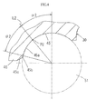
FIG. 1 is a longitudinal sectional view that shows a wheel rolling bearing device according to a first embodiment of the invention; -
FIG 2 is an enlarged longitudinal sectional view that shows a state where a hub spindle, an outer ring member, inner-row balls and outer-row balls are assembled together as shown inFIG. 1 ; -
FIG. 3 is an enlarged longitudinal sectional view that shows an inner-side outer ring raceway surface and an inner-side raceway shoulder of the outer ring member shown inFIG. 2 ; -
FIG. 4 is an enlarged longitudinal sectional view that shows an outer-side outer ring raceway surface and an outer-side raceway shoulder of the outer ring member shown inFIG. 2 ; -
FIG. 5 is a view that illustrates an embodiment in which a boundary portion between the edge of the outer-side outer ring raceway surface and the edge of the outer-side raceway shoulder shown inFIG. 4 is connected without chamfering. -
FIG. 6 is a view that illustrates an embodiment in which the boundary portion between the edge of the outer-side outer ring raceway surface and the edge of the outer-side raceway shoulder shown inFIG. 4 is C-chamfered; -
FIG. 7 is a view that illustrates an embodiment in which the boundary portion between the edge of the outer-side outer ring raceway surface and the edge of the outer-side raceway shoulder shown inFIG. 4 is round-chamfered; -
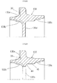
FIG. 8 is a longitudinal sectional view that shows a forging for forming the outer ring member shown inFIG. 1 ; -
FIG. 9 is a longitudinal sectional view that shows a state where an intermediate wall formed inside the forging shown inFIG. 8 is punched by a punch; and -
FIG. 10 is a longitudinal sectional view that shows a state where the forging shown inFIG. 9 is turned and ground into the outer ring member. - An embodiment of the invention will be described.
- A first embodiment of the invention will be described with reference to
FIG. 1 to FIG. 4 . As shown inFIG. 1 , a wheel rolling bearing device (wheel hub unit) includes ahub wheel 10, anouter ring member 30, inner-row balls 50 and outer-row balls 51 forming a double row, and inner-side and outer-side cages hub wheel 10 integrally has ahub spindle 15 that serves as an inner ring member for constituting a double row angular contact ball bearing. - As shown in
FIG. 1 , thehub wheel 10 has thehub spindle 15 and aflange body 11 that are integrally formed. Theflange body 11 is formed at the vehicle outer-side end portion of thehub spindle 15 formed coaxially with thehub spindle 15. Thehub wheel 10 has awheel fitting portion 13 at the vehicle outer-side surface of theflange body 11. The center hole of a wheel (not shown) is fitted to the wheel fittingportion 13 with a brake rotor interposed therebetween. Multiple hub bolts 12 for fastening the wheel are fixedly press-fitted to theflange body 11 at a predetermined pitch. - As shown in
FIG. 1 , an inner-side innerring raceway surface 20 and an outer-side innerring raceway surface 25 are formed on the outer peripheral surface of thehub spindle 15 at a predetermined interval in the axial direction. In the first embodiment, thehub spindle 15 is formed in a stepped shaft such that a portion next to theflange body 11 is large in diameter and a portion next to the distal end is small in diameter. The outer-side innerring raceway surface 25 is formed on the outer peripheral surface of a large-diameter shoulder 16a that is formed at one side (next to the flange body 11) of the large-diameter portion 16 of thehub spindle 15. In addition, aninner ring body 26 is fitted around the outer peripheral surface of the small-diameter portion 17 of thehub spindle 15, and the inner-side innerring raceway surface 20 is formed on the outer peripheral surface of theinner ring body 26. Furthermore, a cylindrical portion extending from the end portion of the small-diameter portion 17 of thehub spindle 15 is clinched radially outward by a clinching tool to form a clinchedportion 18. Thus, theinner ring body 26 is held between the step surface of the small-diameter portion 17 of thehub spindle 15 and the clinchedportion 18. - As shown in
FIG. 1 andFIG. 2 , afitting shaft portion 35 is formed at one end side (inner side in the vehicle widthwise direction) of theouter ring member 30. Thefitting shaft portion 35 is fitted into an assembling hole of a vehicle body-side member, such as a knuckle and a carrier, supported by a suspension (not shown) of a vehicle. A vehicle body-side flange 31 is integrally formed at a portion of the outer peripheral surface of theouter ring member 30, next to thefitting shaft portion 35. The vehicle body-side flange 31 is fastened to the mounting surface of the vehicle body-side member with bolts. An inner-side outerring raceway surface 40 and an outer-side outerring raceway surface 45 that respectively correspond to the inner-side innerring raceway surface 20 and outer-side innerring raceway surface 25 of thehub spindle 15 are formed on the inner peripheral surface of theouter ring member 30 at a predetermined interval in the axial direction. - Multiple inner-
row balls 50 are rollably arranged between the inner-side innerring raceway surface 20 and the inner-side outerring raceway surface 40 in a state where the inner-row balls 50 are retained by an inner-side cage 55. Multiple outer-row balls 51 are rollably arranged between the outer-side innerring raceway surface 25 and the outer-side outerring raceway surface 45 in a state where the outer-row balls 51 are retained by an outer-side cage 56. A required preload is applied to each of the inner-row balls 50 and the outer-row balls 51 by clinching force generated by the above-described clinchedportion 18 of thehub spindle 15. - As shown in
FIG. 2 , where the pitch diameter of the inner-row ball 50-set is D1 and the pitch diameter of the outer-row ball 51-set is D2, D1 and D2 are set so as to satisfy the relationship "D1 < D2". That is, in the first embodiment, in order to achieve weight reduction and high stiffness of the wheel rolling bearing device while maintaining the outside diameter of thefitting shaft portion 35 of theouter ring member 30 at such a diameter that thefitting shaft portion 35 is able to be fitted in the assembling hole of the vehicle body-side member, the pitch diameter D2 of the outer-row ball 51-set is set to be larger than the pitch diameter D1 of the inner-row ball 50-set. Then, the diameter of each of the outer-row balls 51 is set to be smaller than the diameter of each of the inner-row balls 50. Thus, the number of the outer-row balls 51 is larger than the number of the inner-row balls 50. - On the basis of the relationship "D1 < D2", in order to arrange the outer-
row balls 51 at the pitch diameter D2, the outer-side innerring raceway surface 25 formed on the outer peripheral surface of thehub spindle 15 of thehub wheel 10 is formed so as to be larger in diameter than the inner-side innerring raceway surface 20. As shown inFIG. 1 , arecess 10a is formed from the center hole portion of the wheelfitting portion 13 of thehub wheel 10 toward the inner side so as to be large and deep as much as possible with a desired thickness left between the outer-side innerring raceway surface 25 and therecess 10a. Thus, weight reduction of thehub wheel 10 and, consequently, weight reduction of the wheel rolling bearing device, is achieved. - On the basis of the relationship "D1 < D2", in order to arrange the outer-
row balls 51 at the pitch diameter D2, the outer-side outerring raceway surface 45 formed on the inner-peripheral surface of theouter ring member 30 is formed so as to be larger in diameter than the inner-side outerring raceway surface 40. As shown inFIG. 2 , an inner-side raceway shoulder 41 and an outer-side raceway shoulder 46 are formed on the inner peripheral surface of theouter ring member 30. The inner-side raceway shoulder 41 is contiguous with the edge of the inner-side outerring raceway surface 40 at a portion located between the inner-side outerring raceway surface 40 and the outer-side outerring raceway surface 45. The outer-side raceway shoulder 46 is contiguous with the edge of the outer-side outerring raceway surface 45. The inner-side raceway shoulder 41 is formed in a cylindrical shape that is parallel to the axial direction. The outer-side raceway shoulder 46 is formed in a cylindrical shape that is larger in diameter than the inner-side raceway shoulder 41 and that is parallel to the axial direction. A boundary roundedsurface 44 is formed between the outer-side raceway shoulder 46 and the inner-side raceway shoulder 41. - As shown in
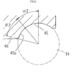
FIG. 3 , the angle of a racewaycircular arc 40a from the intersection point P1 of each inner-row ball 50 with the inner-side outerring raceway surface 40 at a contact angle α1 (the intersection point of the line of action L1, forming the contact angle α1, with the inner-side outer ring raceway surface 40) to the inner-side raceway shoulder 41 is termed θ1. As shown inFIG. 4 , the angle of a racewaycircular arc 45a from the intersection point P2 of each outer-row ball 51 with the outer-side outerring raceway surface 45 at a contact angle α2 (the intersection point of the line of action L2, forming the contact angle α2, with the outer-side outer ring raceway surface 45) to the outer-side raceway shoulder 46 is termed θ2. θ1 and θ2 are set so as to satisfy the relationship "θ1 < θ2". In other words, a ground range (angle) of the outer-side outerring raceway surface 45 is set to be larger than a ground range (angle) of the inner-side outerring raceway surface 40. Note that the contact angle α1 is an angle formed by a plane perpendicular to the rotation axis of the bearing and the line of action L1 of resultant of forces transmitted to each inner-row ball 50 by theinner ring body 26 and theouter ring member 30. In addition, the contact angle α2 is an angle formed by a plane perpendicular to the rotation axis of the bearing and the line of action L2 of resultant force transmitted to each outer-row ball 51 by the hub spindle 15 (inner ring member) and theouter ring member 30. - In the first embodiment, as shown in
FIG. 3 , acircular arc surface 40b and aninclined surface 40c are contiguously formed at the boundary portion between the edge of the inner-side outer ring raceway surface (racewaycircular arc 40a) 40 and the edge of the inner-side raceway shoulder 41. As shown inFIG. 4 , acircular arc surface 45b and aninclined surface 45 are contiguously formed at the boundary portion between the edge of the outer-side outer ring raceway surface (racewaycircular arc 45a) 45 and the edge of the outer-side raceway shoulder 46. - The wheel rolling bearing device according to the first embodiment is configured as described above. Thus, when the pitch diameter D2 of the outer-row ball 51-set of the wheel rolling bearing device is set to be larger than the pitch diameter D1 of the inner-row ball 50-set of the wheel rolling bearing device, it is possible to favorably achieve weight reduction and high stiffness of the wheel rolling bearing device. In addition, when the angle θ2 of the raceway
circular arc 45a of the outer-side outerring raceway surface 45 is set to be larger than the angle θ1 of the racewaycircular arc 40a of the inner-side outerring raceway surface 40, it is possible to favorably prevent the outer-row balls 51 from running on the outer-side raceway shoulder 46, and it is possible to achieve improvement in durability by suppressing a decrease in bearing service life. - In the first embodiment, the case where the
circular arc surface 45b and theinclined surface 45c are contiguously formed at the boundary portion between the edge of the outer-side outer ring raceway surface (racewaycircular arc 45a) 45 and the edge of the outer-side raceway shoulder 46 is illustrated. However, the invention may also be implemented in, for example, a case as shown inFIG. 5 where the boundary portion between the edge of the outer-side outer ring raceway surface (racewaycircular arc 45a) 45 and the edge of the outer-side raceway shoulder 46 is connected without chamfering. The invention may also be implemented in a case as shown inFIG. 6 where a chamferedsurface 45d subjected to C-chamfering is formed at the boundary portion between the edge of the outer-side outer ring raceway surface (racewaycircular arc 45a) 45 and the edge of the outer-side raceway shoulder 46. In addition, the invention may also be implemented in a case as shown inFIG. 7 where achamfered surface 45e subjected to round-chamfering is formed at the boundary portion between the edge of the outer-side outer ring raceway surface (racewaycircular arc 45a) 45 and the edge of the outer-side raceway shoulder 46. - Next, the case where the
outer ring member 30 is formed from a hot forging will be described with reference toFIG. 8 to FIG. 10 . As shown inFIG. 8 , a forging 130 corresponding to theouter ring member 30 will be formed by hot forging. At the outer peripheral side of the forging 130, aturning allowance 130a is formed at portions corresponding to the assembling surface side of the vehicle body-side flange 31 of theouter ring member 30 and the outer peripheral surface side of thefitting shaft portion 35 of theouter ring member 30. At the inner peripheral side of the forging 130, turningallowances fitting shaft portion 35, the inner-side outerring raceway surface 40, the inner-side raceway shoulder 41, the outer-side outerring raceway surface 45 and the outer-side inner hole of theouter ring member 30, and anintermediate wall 130d is formed at a portion corresponding to the inner peripheral side of the inner-side raceway shoulder 41. No turning allowance is formed at portions corresponding to the outer-side raceway shoulder 46 and boundary roundedsurface 44 of theouter ring member 30, but those portions remain as forged skins. The outer-side surface of theintermediate wall 130d is located at the edge, next to the boundary roundedsurface 44, of the inner-side raceway shoulder 41 of theouter ring member 30. The distance (that is, thickness) between the outer-side surface and inner-side surface of theintermediate wall 130d is set to be larger than the axial length of the inner-side raceway shoulder 41 of theouter ring member 30. For example, when the axial length of the inner-side raceway shoulder 41 of theouter ring member 30 is set to about 3 mm or above, the thickness of the intermediate wall is set to about 5 mm or above. - The above described
intermediate wall 130d of the forging 130 is punched by perforating with a punch, or the like, as shown inFIG. 9 . At this time, the diameter of the punched hole is slightly smaller than the inside diameter of the inner-side raceway shoulder 41 of theouter ring member 30. After that, the surface of the forged skin of each of the boundary roundedsurface 44 and the outer-side raceway shoulder 46 is subjected to shot blasting. Thus, the surface of the forged skin of each of the outer-side raceway shoulder 46 and the boundary roundedsurface 44 has a shot-blasted surface subjected to shot blasting. After that, as shown inFIG. 10 , the turningallowances ring raceway surface 40 and the outer-side outerring raceway surface 45, are ground to thereby manufacture theouter ring member 30. - As described above, the surfaces of the outer-
side raceway shoulder 46 and boundary roundedsurface 44 of theouter ring member 30 each have a shot-blasted surface that is obtained by subjecting the surface of the forged skin to shot blasting. Therefore, those surfaces do not need to be subjected to turning. Therefore, it is possible to reduce the weight of a forged material by the amount by which the surface of the outer-side raceway shoulder 46 and the surface of the boundary roundedsurface 44 are turned, and shot blasting may be carried out in a shorter period of time than that of turning. Therefore, cost reduction is efficiently promoted. - Note that the aspect of the invention is not limited to the first embodiment, and the invention may be implemented in various other embodiment without departing from the scope of the invention.
Claims (2)
- A wheel rolling bearing device in which an inner-side inner ring raceway surface and an outer-side inner ring raceway surface are formed at a predetermined interval in an axial direction on an outer peripheral surface of a hub spindle of a hub wheel to which a wheel is connected, an inner-side outer ring raceway surface and an outer-side outer ring raceway surface are formed at a predetermined interval in the axial direction on an inner peripheral surface of an outer ring member arranged on an outer periphery of the hub spindle, inner-row balls are rollably arranged between the inner-side inner ring raceway surface and the inner-side outer ring raceway surface, outer-row balls are rollably arranged between the outer-side inner ring raceway surface and the outer-side outer ring raceway surface, and, where a pitch diameter of the inner-row ball set is D1 and a pitch diameter of the outer-row ball set is D2, D1 and D2 are set so as to satisfy a relationship "D1 < D2", characterized in that:where an angle of a raceway circular arc from an intersection point of each inner-row ball with the inner-side outer ring raceway surface at a contact angle to a boundary portion of an inner-side raceway shoulder is θ1 and an angle of a raceway circular arc from an intersection point of each outer-row ball with the outer-side outer ring raceway surface at a contact angle to a boundary portion of an outer-side raceway shoulder is θ, θ1 and θ2 are set so as to satisfy a relationship "θ1< θ2".
- The wheel rolling bearing device according to claim 1, wherein
the outer ring member is formed by forging, and
a surface of a boundary rounded surface between the outer-side raceway shoulder and the inner-side raceway shoulder and a surface of the outer-side raceway shoulder each have a shot-blasted surface that is obtained by subjecting a surface of a forged skin to shot blasting.
Applications Claiming Priority (1)
| Application Number | Priority Date | Filing Date | Title |
|---|---|---|---|
| JP2011009477A JP5720262B2 (en) | 2011-01-20 | 2011-01-20 | Rolling bearing device for wheels |
Publications (2)
| Publication Number | Publication Date |
|---|---|
| EP2479043A1 true EP2479043A1 (en) | 2012-07-25 |
| EP2479043B1 EP2479043B1 (en) | 2015-01-07 |
Family
ID=45491436
Family Applications (1)
| Application Number | Title | Priority Date | Filing Date |
|---|---|---|---|
| EP12151247.9A Active EP2479043B1 (en) | 2011-01-20 | 2012-01-16 | Wheel rolling bearing device |
Country Status (4)
| Country | Link |
|---|---|
| US (1) | US8708569B2 (en) |
| EP (1) | EP2479043B1 (en) |
| JP (1) | JP5720262B2 (en) |
| CN (1) | CN102602245B (en) |
Families Citing this family (5)
| Publication number | Priority date | Publication date | Assignee | Title |
|---|---|---|---|---|
| JP5720262B2 (en) * | 2011-01-20 | 2015-05-20 | 株式会社ジェイテクト | Rolling bearing device for wheels |
| JP6212855B2 (en) * | 2012-12-03 | 2017-10-18 | 株式会社ジェイテクト | Wheel bearing device |
| JP6957958B2 (en) | 2017-04-24 | 2021-11-02 | 日本精工株式会社 | Hub unit bearing |
| US11731456B2 (en) * | 2019-05-24 | 2023-08-22 | Aktiebolaget Skf | Wheel hub bearing with radial stiffening |
| CN110848267A (en) * | 2019-12-27 | 2020-02-28 | 瓦房店轴承集团国家轴承工程技术研究中心有限公司 | Yaw bearing of S-shaped positioning rotary diameter structure |
Citations (6)
| Publication number | Priority date | Publication date | Assignee | Title |
|---|---|---|---|---|
| JP2004108449A (en) | 2002-09-17 | 2004-04-08 | Koyo Seiko Co Ltd | Rolling bearing device |
| EP1722115A2 (en) * | 2005-05-12 | 2006-11-15 | Ntn Corporation | Wheel support bearing assembly |
| EP1944518A1 (en) * | 2005-09-30 | 2008-07-16 | Ntn Corporation | Bearing device for wheel |
| US20090148091A1 (en) * | 2006-08-17 | 2009-06-11 | Ntn Corporation | Wheel Bearing Apparatus |
| US20090232435A1 (en) * | 2006-11-14 | 2009-09-17 | Ntn Corporation | Wheel Bearing Apparatus For A Vehicle |
| US20090252447A1 (en) * | 2006-12-20 | 2009-10-08 | Ntn Corporation | Hub Wheel Of A Wheel Bearing Apparatus And A Manufacturing Method Thereof |
Family Cites Families (16)
| Publication number | Priority date | Publication date | Assignee | Title |
|---|---|---|---|---|
| DE10331936B4 (en) * | 2003-07-15 | 2017-01-26 | Schaeffler Technologies AG & Co. KG | Wheel bearing unit in angular ball bearing design |
| EP3611392A1 (en) * | 2003-10-14 | 2020-02-19 | Aktiebolaget SKF | Asymmetric wheel hub rolling bearing assembly |
| EP1729021B1 (en) * | 2005-06-02 | 2010-01-20 | Ntn Corporation | Wheel support bearing assembly |
| KR20080025122A (en) * | 2005-07-13 | 2008-03-19 | 엔티엔 가부시키가이샤 | Angular contact ball bearing and joint device of robot arm |
| JP2007024273A (en) * | 2005-07-20 | 2007-02-01 | Ntn Corp | Method of manufacturing bearing device for wheel |
| WO2007049437A1 (en) * | 2005-10-27 | 2007-05-03 | Ntn Corporation | Bearing device for wheel |
| DE102006004297B4 (en) * | 2006-01-31 | 2019-03-07 | Schaeffler Kg | Asymmetrical three-row rolling bearing |
| JP2008039106A (en) * | 2006-08-08 | 2008-02-21 | Ntn Corp | Bearing device for wheel |
| JP2008115949A (en) * | 2006-11-06 | 2008-05-22 | Ntn Corp | Bearing device for wheel |
| JP2008175262A (en) * | 2007-01-17 | 2008-07-31 | Ntn Corp | Wheel bearing device and its manufacturing method |
| JP2008240769A (en) * | 2007-03-26 | 2008-10-09 | Jtekt Corp | Double-row ball bearing |
| JP2009162335A (en) * | 2008-01-08 | 2009-07-23 | Ntn Corp | Bearing device for wheel |
| JP2010156455A (en) * | 2008-12-04 | 2010-07-15 | Jtekt Corp | Rolling bearing device |
| EP2503169B1 (en) * | 2009-11-20 | 2019-01-09 | NSK Ltd. | Tandem angular type ball bearing |
| JP5570297B2 (en) * | 2010-05-20 | 2014-08-13 | Ntn株式会社 | Wheel bearing device |
| JP5720262B2 (en) * | 2011-01-20 | 2015-05-20 | 株式会社ジェイテクト | Rolling bearing device for wheels |
-
2011
- 2011-01-20 JP JP2011009477A patent/JP5720262B2/en active Active
- 2011-12-31 CN CN201110459909.XA patent/CN102602245B/en active Active
-
2012
- 2012-01-09 US US13/345,931 patent/US8708569B2/en active Active
- 2012-01-16 EP EP12151247.9A patent/EP2479043B1/en active Active
Patent Citations (6)
| Publication number | Priority date | Publication date | Assignee | Title |
|---|---|---|---|---|
| JP2004108449A (en) | 2002-09-17 | 2004-04-08 | Koyo Seiko Co Ltd | Rolling bearing device |
| EP1722115A2 (en) * | 2005-05-12 | 2006-11-15 | Ntn Corporation | Wheel support bearing assembly |
| EP1944518A1 (en) * | 2005-09-30 | 2008-07-16 | Ntn Corporation | Bearing device for wheel |
| US20090148091A1 (en) * | 2006-08-17 | 2009-06-11 | Ntn Corporation | Wheel Bearing Apparatus |
| US20090232435A1 (en) * | 2006-11-14 | 2009-09-17 | Ntn Corporation | Wheel Bearing Apparatus For A Vehicle |
| US20090252447A1 (en) * | 2006-12-20 | 2009-10-08 | Ntn Corporation | Hub Wheel Of A Wheel Bearing Apparatus And A Manufacturing Method Thereof |
Also Published As
| Publication number | Publication date |
|---|---|
| US8708569B2 (en) | 2014-04-29 |
| JP2012149721A (en) | 2012-08-09 |
| JP5720262B2 (en) | 2015-05-20 |
| EP2479043B1 (en) | 2015-01-07 |
| CN102602245A (en) | 2012-07-25 |
| US20120189236A1 (en) | 2012-07-26 |
| CN102602245B (en) | 2016-01-20 |
Similar Documents
| Publication | Publication Date | Title |
|---|---|---|
| EP2422994B1 (en) | Vehicle hub unit | |
| EP2479043B1 (en) | Wheel rolling bearing device | |
| EP2618012A1 (en) | Wheel hub rolling bearing unit for a motor vehicle with a cold forged inner ring and a seal | |
| JP2009008165A (en) | Wheel bearing device | |
| US20150191044A1 (en) | Bearing module | |
| US8763255B2 (en) | Manufacturing method for wheel rolling bearing device, and wheel rolling bearing device | |
| JP6366233B2 (en) | Wheel bearing device | |
| JP6007655B2 (en) | Wheel bearing device | |
| US8770852B2 (en) | Wheel bearing device | |
| JP5415999B2 (en) | Wheel bearing device | |
| JP5099875B2 (en) | Wheel bearing device | |
| JP2012219855A (en) | Bearing device for wheel | |
| JP6224402B2 (en) | Method for manufacturing outer member of wheel bearing device | |
| JP6054124B2 (en) | Wheel bearing device | |
| JP6429441B2 (en) | Wheel bearing device, intermediate body, and manufacturing method thereof | |
| JP5024850B2 (en) | Wheel bearing device | |
| JP5236097B2 (en) | Wheel bearing device | |
| WO2015147245A1 (en) | Bearing device for wheel | |
| EP2570269A1 (en) | Hub Unit | |
| EP2106928B1 (en) | Wheel rolling bearing assembly and manufacturing method thereof | |
| JP2008045699A (en) | Bearing device for wheel, and its manufacturing method | |
| JP2008162356A (en) | Bearing device for wheel | |
| JP2022139735A (en) | Wheel bearing device | |
| JP2007113719A (en) | Bearing device for wheel | |
| JP2012148693A (en) | Rolling bearing device for wheel |
Legal Events
| Date | Code | Title | Description |
|---|---|---|---|
| PUAI | Public reference made under article 153(3) epc to a published international application that has entered the european phase |
Free format text: ORIGINAL CODE: 0009012 |
|
| AK | Designated contracting states |
Kind code of ref document: A1 Designated state(s): AL AT BE BG CH CY CZ DE DK EE ES FI FR GB GR HR HU IE IS IT LI LT LU LV MC MK MT NL NO PL PT RO RS SE SI SK SM TR |
|
| AX | Request for extension of the european patent |
Extension state: BA ME |
|
| 17P | Request for examination filed |
Effective date: 20130124 |
|
| 17Q | First examination report despatched |
Effective date: 20131211 |
|
| GRAP | Despatch of communication of intention to grant a patent |
Free format text: ORIGINAL CODE: EPIDOSNIGR1 |
|
| RIC1 | Information provided on ipc code assigned before grant |
Ipc: F16C 33/58 20060101ALI20140610BHEP Ipc: F16C 19/18 20060101ALI20140610BHEP Ipc: B60B 27/00 20060101AFI20140610BHEP |
|
| INTG | Intention to grant announced |
Effective date: 20140715 |
|
| GRAS | Grant fee paid |
Free format text: ORIGINAL CODE: EPIDOSNIGR3 |
|
| GRAA | (expected) grant |
Free format text: ORIGINAL CODE: 0009210 |
|
| AK | Designated contracting states |
Kind code of ref document: B1 Designated state(s): AL AT BE BG CH CY CZ DE DK EE ES FI FR GB GR HR HU IE IS IT LI LT LU LV MC MK MT NL NO PL PT RO RS SE SI SK SM TR |
|
| REG | Reference to a national code |
Ref country code: GB Ref legal event code: FG4D |
|
| REG | Reference to a national code |
Ref country code: CH Ref legal event code: EP |
|
| REG | Reference to a national code |
Ref country code: IE Ref legal event code: FG4D |
|
| REG | Reference to a national code |
Ref country code: AT Ref legal event code: REF Ref document number: 705410 Country of ref document: AT Kind code of ref document: T Effective date: 20150215 |
|
| REG | Reference to a national code |
Ref country code: DE Ref legal event code: R096 Ref document number: 602012004705 Country of ref document: DE Effective date: 20150219 |
|
| REG | Reference to a national code |
Ref country code: NL Ref legal event code: VDEP Effective date: 20150107 |
|
| REG | Reference to a national code |
Ref country code: AT Ref legal event code: MK05 Ref document number: 705410 Country of ref document: AT Kind code of ref document: T Effective date: 20150107 |
|
| REG | Reference to a national code |
Ref country code: LT Ref legal event code: MG4D |
|
| PG25 | Lapsed in a contracting state [announced via postgrant information from national office to epo] |
Ref country code: BE Free format text: LAPSE BECAUSE OF NON-PAYMENT OF DUE FEES Effective date: 20150131 |
|
| PG25 | Lapsed in a contracting state [announced via postgrant information from national office to epo] |
Ref country code: SE Free format text: LAPSE BECAUSE OF FAILURE TO SUBMIT A TRANSLATION OF THE DESCRIPTION OR TO PAY THE FEE WITHIN THE PRESCRIBED TIME-LIMIT Effective date: 20150107 Ref country code: LT Free format text: LAPSE BECAUSE OF FAILURE TO SUBMIT A TRANSLATION OF THE DESCRIPTION OR TO PAY THE FEE WITHIN THE PRESCRIBED TIME-LIMIT Effective date: 20150107 Ref country code: NO Free format text: LAPSE BECAUSE OF FAILURE TO SUBMIT A TRANSLATION OF THE DESCRIPTION OR TO PAY THE FEE WITHIN THE PRESCRIBED TIME-LIMIT Effective date: 20150407 Ref country code: HR Free format text: LAPSE BECAUSE OF FAILURE TO SUBMIT A TRANSLATION OF THE DESCRIPTION OR TO PAY THE FEE WITHIN THE PRESCRIBED TIME-LIMIT Effective date: 20150107 Ref country code: FI Free format text: LAPSE BECAUSE OF FAILURE TO SUBMIT A TRANSLATION OF THE DESCRIPTION OR TO PAY THE FEE WITHIN THE PRESCRIBED TIME-LIMIT Effective date: 20150107 Ref country code: BG Free format text: LAPSE BECAUSE OF FAILURE TO SUBMIT A TRANSLATION OF THE DESCRIPTION OR TO PAY THE FEE WITHIN THE PRESCRIBED TIME-LIMIT Effective date: 20150407 Ref country code: ES Free format text: LAPSE BECAUSE OF FAILURE TO SUBMIT A TRANSLATION OF THE DESCRIPTION OR TO PAY THE FEE WITHIN THE PRESCRIBED TIME-LIMIT Effective date: 20150107 |
|
| REG | Reference to a national code |
Ref country code: CH Ref legal event code: PL |
|
| PG25 | Lapsed in a contracting state [announced via postgrant information from national office to epo] |
Ref country code: LV Free format text: LAPSE BECAUSE OF FAILURE TO SUBMIT A TRANSLATION OF THE DESCRIPTION OR TO PAY THE FEE WITHIN THE PRESCRIBED TIME-LIMIT Effective date: 20150107 Ref country code: IS Free format text: LAPSE BECAUSE OF FAILURE TO SUBMIT A TRANSLATION OF THE DESCRIPTION OR TO PAY THE FEE WITHIN THE PRESCRIBED TIME-LIMIT Effective date: 20150507 Ref country code: GR Free format text: LAPSE BECAUSE OF FAILURE TO SUBMIT A TRANSLATION OF THE DESCRIPTION OR TO PAY THE FEE WITHIN THE PRESCRIBED TIME-LIMIT Effective date: 20150408 Ref country code: RS Free format text: LAPSE BECAUSE OF FAILURE TO SUBMIT A TRANSLATION OF THE DESCRIPTION OR TO PAY THE FEE WITHIN THE PRESCRIBED TIME-LIMIT Effective date: 20150107 Ref country code: NL Free format text: LAPSE BECAUSE OF FAILURE TO SUBMIT A TRANSLATION OF THE DESCRIPTION OR TO PAY THE FEE WITHIN THE PRESCRIBED TIME-LIMIT Effective date: 20150107 Ref country code: PL Free format text: LAPSE BECAUSE OF FAILURE TO SUBMIT A TRANSLATION OF THE DESCRIPTION OR TO PAY THE FEE WITHIN THE PRESCRIBED TIME-LIMIT Effective date: 20150107 Ref country code: AT Free format text: LAPSE BECAUSE OF FAILURE TO SUBMIT A TRANSLATION OF THE DESCRIPTION OR TO PAY THE FEE WITHIN THE PRESCRIBED TIME-LIMIT Effective date: 20150107 |
|
| REG | Reference to a national code |
Ref country code: DE Ref legal event code: R097 Ref document number: 602012004705 Country of ref document: DE |
|
| PG25 | Lapsed in a contracting state [announced via postgrant information from national office to epo] |
Ref country code: MC Free format text: LAPSE BECAUSE OF FAILURE TO SUBMIT A TRANSLATION OF THE DESCRIPTION OR TO PAY THE FEE WITHIN THE PRESCRIBED TIME-LIMIT Effective date: 20150107 Ref country code: RO Free format text: LAPSE BECAUSE OF FAILURE TO SUBMIT A TRANSLATION OF THE DESCRIPTION OR TO PAY THE FEE WITHIN THE PRESCRIBED TIME-LIMIT Effective date: 20150107 Ref country code: EE Free format text: LAPSE BECAUSE OF FAILURE TO SUBMIT A TRANSLATION OF THE DESCRIPTION OR TO PAY THE FEE WITHIN THE PRESCRIBED TIME-LIMIT Effective date: 20150107 Ref country code: SK Free format text: LAPSE BECAUSE OF FAILURE TO SUBMIT A TRANSLATION OF THE DESCRIPTION OR TO PAY THE FEE WITHIN THE PRESCRIBED TIME-LIMIT Effective date: 20150107 Ref country code: DK Free format text: LAPSE BECAUSE OF FAILURE TO SUBMIT A TRANSLATION OF THE DESCRIPTION OR TO PAY THE FEE WITHIN THE PRESCRIBED TIME-LIMIT Effective date: 20150107 Ref country code: CH Free format text: LAPSE BECAUSE OF NON-PAYMENT OF DUE FEES Effective date: 20150131 Ref country code: CZ Free format text: LAPSE BECAUSE OF FAILURE TO SUBMIT A TRANSLATION OF THE DESCRIPTION OR TO PAY THE FEE WITHIN THE PRESCRIBED TIME-LIMIT Effective date: 20150107 Ref country code: LI Free format text: LAPSE BECAUSE OF NON-PAYMENT OF DUE FEES Effective date: 20150131 |
|
| REG | Reference to a national code |
Ref country code: IE Ref legal event code: MM4A |
|
| PLBE | No opposition filed within time limit |
Free format text: ORIGINAL CODE: 0009261 |
|
| STAA | Information on the status of an ep patent application or granted ep patent |
Free format text: STATUS: NO OPPOSITION FILED WITHIN TIME LIMIT |
|
| 26N | No opposition filed |
Effective date: 20151008 |
|
| REG | Reference to a national code |
Ref country code: FR Ref legal event code: ST Effective date: 20151116 |
|
| PG25 | Lapsed in a contracting state [announced via postgrant information from national office to epo] |
Ref country code: IT Free format text: LAPSE BECAUSE OF FAILURE TO SUBMIT A TRANSLATION OF THE DESCRIPTION OR TO PAY THE FEE WITHIN THE PRESCRIBED TIME-LIMIT Effective date: 20150107 |
|
| PG25 | Lapsed in a contracting state [announced via postgrant information from national office to epo] |
Ref country code: IE Free format text: LAPSE BECAUSE OF NON-PAYMENT OF DUE FEES Effective date: 20150116 |
|
| PG25 | Lapsed in a contracting state [announced via postgrant information from national office to epo] |
Ref country code: SI Free format text: LAPSE BECAUSE OF FAILURE TO SUBMIT A TRANSLATION OF THE DESCRIPTION OR TO PAY THE FEE WITHIN THE PRESCRIBED TIME-LIMIT Effective date: 20150107 Ref country code: FR Free format text: LAPSE BECAUSE OF NON-PAYMENT OF DUE FEES Effective date: 20150309 |
|
| PG25 | Lapsed in a contracting state [announced via postgrant information from national office to epo] |
Ref country code: BE Free format text: LAPSE BECAUSE OF FAILURE TO SUBMIT A TRANSLATION OF THE DESCRIPTION OR TO PAY THE FEE WITHIN THE PRESCRIBED TIME-LIMIT Effective date: 20150107 |
|
| GBPC | Gb: european patent ceased through non-payment of renewal fee |
Effective date: 20160116 |
|
| PG25 | Lapsed in a contracting state [announced via postgrant information from national office to epo] |
Ref country code: GB Free format text: LAPSE BECAUSE OF NON-PAYMENT OF DUE FEES Effective date: 20160116 |
|
| PG25 | Lapsed in a contracting state [announced via postgrant information from national office to epo] |
Ref country code: MT Free format text: LAPSE BECAUSE OF FAILURE TO SUBMIT A TRANSLATION OF THE DESCRIPTION OR TO PAY THE FEE WITHIN THE PRESCRIBED TIME-LIMIT Effective date: 20150107 |
|
| PG25 | Lapsed in a contracting state [announced via postgrant information from national office to epo] |
Ref country code: HU Free format text: LAPSE BECAUSE OF FAILURE TO SUBMIT A TRANSLATION OF THE DESCRIPTION OR TO PAY THE FEE WITHIN THE PRESCRIBED TIME-LIMIT; INVALID AB INITIO Effective date: 20120116 Ref country code: SM Free format text: LAPSE BECAUSE OF FAILURE TO SUBMIT A TRANSLATION OF THE DESCRIPTION OR TO PAY THE FEE WITHIN THE PRESCRIBED TIME-LIMIT Effective date: 20150107 |
|
| PG25 | Lapsed in a contracting state [announced via postgrant information from national office to epo] |
Ref country code: CY Free format text: LAPSE BECAUSE OF FAILURE TO SUBMIT A TRANSLATION OF THE DESCRIPTION OR TO PAY THE FEE WITHIN THE PRESCRIBED TIME-LIMIT Effective date: 20150107 |
|
| PG25 | Lapsed in a contracting state [announced via postgrant information from national office to epo] |
Ref country code: PT Free format text: LAPSE BECAUSE OF FAILURE TO SUBMIT A TRANSLATION OF THE DESCRIPTION OR TO PAY THE FEE WITHIN THE PRESCRIBED TIME-LIMIT Effective date: 20150507 |
|
| PG25 | Lapsed in a contracting state [announced via postgrant information from national office to epo] |
Ref country code: TR Free format text: LAPSE BECAUSE OF FAILURE TO SUBMIT A TRANSLATION OF THE DESCRIPTION OR TO PAY THE FEE WITHIN THE PRESCRIBED TIME-LIMIT Effective date: 20150107 |
|
| PG25 | Lapsed in a contracting state [announced via postgrant information from national office to epo] |
Ref country code: LU Free format text: LAPSE BECAUSE OF NON-PAYMENT OF DUE FEES Effective date: 20150116 |
|
| PG25 | Lapsed in a contracting state [announced via postgrant information from national office to epo] |
Ref country code: MK Free format text: LAPSE BECAUSE OF FAILURE TO SUBMIT A TRANSLATION OF THE DESCRIPTION OR TO PAY THE FEE WITHIN THE PRESCRIBED TIME-LIMIT Effective date: 20150107 |
|
| PG25 | Lapsed in a contracting state [announced via postgrant information from national office to epo] |
Ref country code: AL Free format text: LAPSE BECAUSE OF FAILURE TO SUBMIT A TRANSLATION OF THE DESCRIPTION OR TO PAY THE FEE WITHIN THE PRESCRIBED TIME-LIMIT Effective date: 20150107 |
|
| PGFP | Annual fee paid to national office [announced via postgrant information from national office to epo] |
Ref country code: DE Payment date: 20231128 Year of fee payment: 13 |