EP2476916A2 - Kolben-Zylinder-Einheit mit Vorrichtung zur Positionsbestimmung - Google Patents
Kolben-Zylinder-Einheit mit Vorrichtung zur Positionsbestimmung Download PDFInfo
- Publication number
- EP2476916A2 EP2476916A2 EP11010014A EP11010014A EP2476916A2 EP 2476916 A2 EP2476916 A2 EP 2476916A2 EP 11010014 A EP11010014 A EP 11010014A EP 11010014 A EP11010014 A EP 11010014A EP 2476916 A2 EP2476916 A2 EP 2476916A2
- Authority
- EP
- European Patent Office
- Prior art keywords
- piston
- cylinder unit
- cylinder
- unit according
- excitation means
- Prior art date
- Legal status (The legal status is an assumption and is not a legal conclusion. Google has not performed a legal analysis and makes no representation as to the accuracy of the status listed.)
- Granted
Links
- 230000005284 excitation Effects 0.000 claims abstract description 21
- 238000010276 construction Methods 0.000 claims description 9
- 230000010355 oscillation Effects 0.000 claims description 7
- 238000011156 evaluation Methods 0.000 claims description 6
- 239000003302 ferromagnetic material Substances 0.000 claims description 3
- 230000000087 stabilizing effect Effects 0.000 claims description 2
- 239000000463 material Substances 0.000 description 4
- 238000000034 method Methods 0.000 description 3
- 230000004048 modification Effects 0.000 description 3
- 238000012986 modification Methods 0.000 description 3
- 229910000906 Bronze Inorganic materials 0.000 description 2
- OKTJSMMVPCPJKN-UHFFFAOYSA-N Carbon Chemical compound [C] OKTJSMMVPCPJKN-UHFFFAOYSA-N 0.000 description 2
- 239000010974 bronze Substances 0.000 description 2
- 229910052799 carbon Inorganic materials 0.000 description 2
- 239000004020 conductor Substances 0.000 description 2
- KUNSUQLRTQLHQQ-UHFFFAOYSA-N copper tin Chemical compound [Cu].[Sn] KUNSUQLRTQLHQQ-UHFFFAOYSA-N 0.000 description 2
- 238000010586 diagram Methods 0.000 description 2
- 230000000694 effects Effects 0.000 description 2
- 239000010720 hydraulic oil Substances 0.000 description 2
- 230000015572 biosynthetic process Effects 0.000 description 1
- 230000006735 deficit Effects 0.000 description 1
- 239000000428 dust Substances 0.000 description 1
- 238000005516 engineering process Methods 0.000 description 1
- 239000012530 fluid Substances 0.000 description 1
- 238000009413 insulation Methods 0.000 description 1
- 238000002955 isolation Methods 0.000 description 1
- 230000005291 magnetic effect Effects 0.000 description 1
Images

Classifications
-
- F—MECHANICAL ENGINEERING; LIGHTING; HEATING; WEAPONS; BLASTING
- F15—FLUID-PRESSURE ACTUATORS; HYDRAULICS OR PNEUMATICS IN GENERAL
- F15B—SYSTEMS ACTING BY MEANS OF FLUIDS IN GENERAL; FLUID-PRESSURE ACTUATORS, e.g. SERVOMOTORS; DETAILS OF FLUID-PRESSURE SYSTEMS, NOT OTHERWISE PROVIDED FOR
- F15B15/00—Fluid-actuated devices for displacing a member from one position to another; Gearing associated therewith
- F15B15/20—Other details, e.g. assembly with regulating devices
- F15B15/28—Means for indicating the position, e.g. end of stroke
- F15B15/2815—Position sensing, i.e. means for continuous measurement of position, e.g. LVDT
- F15B15/2869—Position sensing, i.e. means for continuous measurement of position, e.g. LVDT using electromagnetic radiation, e.g. radar or microwaves
Definitions
- the present invention relates to a piston-cylinder unit with a device for position determination.
- the position determination of a cylinder piston is a necessary and important task in a number of technical applications.
- the exact position of the cylinder piston often plays a major role in the targeted control of the piston-cylinder unit.
- the reliability of a piston-cylinder unit can be significantly increased by determining the position, since the inlet of the hydraulic medium, in particular the hydraulic fluid can be precisely controlled in the extreme positions of the cylinder piston and thus stopped in time.
- a precise position determination in the automatic control of the piston-cylinder units in construction equipment or lifting equipment is important.
- the piston-cylinder unit actuates in a conventional manner the working equipment of the construction machine or the lifting device.
- a sufficiently accurate position determination of the piston-cylinder unit increases the quality of the control and is therefore urgently needed.
- the current position of the cylinder piston is detected by arranged pull-potentiometer.
- the object of the present invention is to provide a piston-cylinder unit with a position-determining device, which has a satisfactory stability and robustness and yet is easy and inexpensive to produce and install.
- the piston-cylinder unit is preferably designed as a hydraulic cylinder and used as a hydraulic medium particularly preferably a hydraulic oil.
- the device for position determination comprises at least one excitation means which is directly or indirectly electrically connected to the cylinder jacket and indirectly or directly to the cylinder piston of the piston-cylinder unit.
- Cylinder shell and cylinder pistons each act as an electrode of a series resonant circuit.
- the piston rod and the cylinder jacket form a series inductance.
- Opposing piston and cylinder surfaces with hydraulic media form a capacity. Accordingly, the complete piston-cylinder unit can be regarded as a resonant circuit.
- the excitation means serves to excite the electrical series resonant circuit for oscillation in its resonant frequency.
- the self-adjusting resonance frequency of a resonant circuit is basically due to the capacitance or inductance. Consequently, based on the resonant frequency, the variable capacity of the piston-cylinder unit can be deduced, the capacity and inductance depending on the current piston position. Thus, the actual and exact piston position can be determined from the resonance frequency.
- a resonant frequency characterizing electrical signal on the device can be tapped.
- the invention takes advantage of the fact that the piston-cylinder unit is suitable without modification for the formation of an electrical resonant circuit.
- no external sensors or measuring sensors or additional electrodes need to be arranged on or within the piston-cylinder unit.
- the known components of a piston-cylinder unit, such as the cylinder jacket and the cylinder piston are used to form a series resonant circuit.
- the excitation means comprises an oscillator circuit which is electrically connected to the piston-cylinder unit.
- a particularly advantageous is a Hartley oscillator circuit.
- the resonant frequency of the resonant circuit is classified as a high-frequency signal and experience has shown that it is in the megahertz range.
- the piston-cylinder unit can act as an antenna that emits electromagnetic waves.
- advantageously at least a part of the device for determining the position is arranged within the cylinder housing or the cylinder jacket.
- the excitation means in the interior of the piston-cylinder unit or a dedicated cavity of the piston-cylinder unit is arranged.
- the shielding effect of the cylinder jacket has an advantageous effect on the EMC characteristics of the device or the piston-cylinder unit.
- the externally arranged device for position determination in particular covers the excitation means and prevents the emission of the electromagnetic waves.
- An advantageous magnetic shield which is made in particular of a ferromagnetic material turns out to be advantageous.
- other shielding materials are also conceivable which suitably cover and shield the device for determining the position.
- the use of at least one EMI filter proves to be advantageous.
- the signal to be picked off which characterizes the resonant frequency
- This voltage has during the oscillation process of the piston-cylinder unit an oscillating waveform, advantageously is galvanically isolated, and used as a rectangular signal for digital evaluation.
- the vibration behavior is damped and influenced by the resonant circuit components or external influences.
- a circuit device for stabilizing the tapped voltage may be advantageous.
- the external influences include moisture, dust deposits, etc.
- an evaluation means is provided, which is suitable for evaluating the signal and for outputting the present piston position.
- the evaluation means may be a correspondingly configured microcontroller or a suitable analogue circuit device.
- the evaluation is either permanently connected to the piston-cylinder unit or detachably connected to this.
- an additional inductance between the excitation means and the piston or between the excitation means and the cylinder jacket can advantageously be arranged. This can be advantageous for EMC technical reasons.
- the contact between the excitation means and the piston-cylinder unit is advantageously produced by a sliding contact.
- the contact between the movable part of the piston-cylinder unit, in particular the piston rod is preferably realized by means of sliding contact. It proves useful brush contact between the piston rod and excitation means, the brush during the piston movement slides along the piston rod surface.
- the brush is preferably made of carbon, bronze or other suitable material.
- the contacting between the piston rod and the excitation means can be effected by means of a capacitive or conductive ring.
- the ring is slidably disposed coaxially with the piston rod on the surface thereof. The use of a capacitive ring creates an additional constant capacitance connected in series with the tank circuit.
- the ring consists of a conductive material, which is directly or indirectly connected to the excitation means, wherein between the ring and piston rod, a dielectric is arranged or the conductive ring directly with the Piston rod is galvanically connected.
- insulation between the piston-cylinder unit and the oscillator or the excitation means can be achieved by inserting a transformer.
- the leakage inductance of the transformer can also be used to reduce the resonance frequency.
- the present invention further relates to a construction machine or a lifting device with a piston-cylinder unit according to one of the preceding advantageous embodiments.
- the construction machine according to the invention or the lifting device obviously has the same advantages and properties as the above-described piston-cylinder unit, which is why at this point a further explanation is dispensed with.
- piston-cylinder unit is by no means limited to construction machinery or lifting devices. Possible areas of application arise in aircraft or generally in all machines / devices with hydraulic / pneumatic technology.
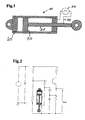
- FIG. 1 shows the piston-cylinder unit 10 according to the invention with a device for position determination.
- the construction of the piston-cylinder unit 10 is similar to a known piston-cylinder unit.
- the unit 10 comprises a tubular cylinder jacket 20, in the cavity of which a piston 30 with arranged piston rod 31 is mounted linearly displaceable.
- the piston-cylinder unit 10 is preferably used in construction machines or lifting devices, wherein a fixed implement is driven by the piston-cylinder unit 10.
- the automatic operation of the implement requires the precise positioning of the piston 30th
- the piston 30 forms a first electrode of a series resonant circuit and the cylinder jacket 20, the second electrode of the series resonant circuit.
- the piston 30, nor the piston rod 31 are conductively connected to the cylinder jacket 20, but instead via seals between the piston 30 and cylinder shell 20 and in the opening region of the cylinder jacket 20th and the exiting piston rod 31 slidably mounted.
- a hydraulic medium in particular hydraulic oil, which acts as a dielectric between the two electrodes.
- an oscillator 50 which is on the electrical lines 40 once with the cylinder jacket 20 and the piston rod 31 in conjunction.
- the oscillator After excitation of the resonant circuit via the oscillator 50, the oscillator oscillates at its resonant frequency.
- the formed impedance of piston 30 and cylinder shell 20 depends on the respective position of the piston 30 in the cavity of the cylinder. Since the capacitance or inductance of the resonant circuit influence the adjusting resonant frequency, a conclusion about the present impedance of the piston-cylinder unit 10 can be made on the basis of the detected resonant frequency.
- a corresponding output voltage V out is tapped off in the region of the oscillator 50 and analyzed or interpreted by a corresponding evaluation means, not shown, and optionally indicated optically or acoustically.
- the electrical contact between the oscillator 50 and the movable piston rod 31 is realized by means of a sliding contact.
- the piston rod 31 facing the end of the connecting line 40 of the oscillator 50 has for this purpose a brush contact, which extends slidably on the surface of the piston rod 31.
- the brushes of this contact point are preferably made of carbon, bronze or other suitable material.
- FIG. 2 shows a circuit diagram of the inventive piston-cylinder unit 10 with the corresponding interconnected device for determining position.
- the marked output voltage V out has an oscillating signal course and accordingly describes the present resonance frequency of the entire resonant circuit. This voltage or the voltage curve changes depending on the corresponding piston position of the piston-cylinder unit 10th
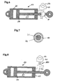
- FIG. 3 is that out FIG. 1 known piston-cylinder unit 10 according to the invention, this being supplemented by an additional inductance between the oscillator 50 and the cylinder jacket 20. Since the resonant circuit formed oscillates in a high-frequency resonant frequency range, the resonant frequency can be significantly reduced by the additionally series-connected inductor 60.
- an additional shield 70 installed, which covers the area around the oscillator 50, and shields the released electromagnetic waves due to the antenna characteristics of the piston-cylinder unit 10 to the environment.
- a shield 70 is made of a ferromagnetic material, for example. Of course, all materials are conceivable that ensure adequate shielding of the electromagnetic waves.
- the cylinder jacket 20 can be misused as a shielding means.
- the oscillator 50 is mounted in the cavity of the cylinder jacket 20.
- spark suppressors may be connected at the outputs of the oscillator 50.
- connection between oscillator 50 and piston rod 31 can be implemented by means of a capacitive or conductive ring 80. As in FIG. 6 shown, runs such a ring 80 coaxial with the piston rod 31 and slidably on the surface of the piston rod 31.
- FIG. 7 A sectional view along the section axis AA is the FIG. 7 refer to.
- This shows the capacitive ring 80, which is made of a conductive material. Between the piston rod 31 and the capacitive ring 80 is a dielectric 90. Ring 80 and piston rod 31 form a constant capacitance, which is connected in series with the resonant circuit.
- FIG. 8 shows a possible decoupling of the oscillator 50 from the piston-cylinder unit 10.
- the electrical connection is made via a transformer 100.
- the internal inductance of the transformer 100 acts as an additional series-connected inductance of the resonant circuit, whereby the self-adjusting resonant frequency is further reduced.
- electrical isolation between the cylinder and the oscillator 50 is realized by the transformer 100.
Landscapes
- Engineering & Computer Science (AREA)
- Physics & Mathematics (AREA)
- Fluid Mechanics (AREA)
- Mechanical Engineering (AREA)
- General Engineering & Computer Science (AREA)
- Electromagnetism (AREA)
- Health & Medical Sciences (AREA)
- Radar, Positioning & Navigation (AREA)
- Remote Sensing (AREA)
- Toxicology (AREA)
- Actuator (AREA)
- Measurement Of Length, Angles, Or The Like Using Electric Or Magnetic Means (AREA)
- Pistons, Piston Rings, And Cylinders (AREA)
Abstract
Description
- Die vorliegende Erfindung betrifft eine Kolben-Zylinder-Einheit mit einer Vorrichtung zur Positionsbestimmung.
- Die Positionsbestimmung eines Zylinderkolbens stellt eine notwendige und wichtige Aufgabe bei einer Reihe von technischen Anwendungen dar. Insbesondere spielt die exakte Position des Zylinderkolbens oftmals eine tragende Rolle bei der zielgerichteten Ansteuerung der Kolben-Zylinder-Einheit. Darüber hinaus lässt sich durch die Positionsbestimmung die Betriebssicherheit einer Kolben-Zylinder-Einheit maßgeblich erhöhen, da der Einlaß des Hydraulikmediums, insbesondere der Hydraulikflüssigkeit, in den Extrempositionen des Zylinderkolbens exakt gesteuert und folglich rechtzeitig gestoppt werden kann.
- Auch ist eine präzise Positionsbestimmung bei der automatischen Ansteuerung der Kolben-Zylinder-Einheiten bei Baumaschinen bzw. Hubgeräten von Bedeutung. Die Kolben-Zylinder-Einheit betätigt in üblicher Weise das Arbeitsgerät der Baumaschine bzw. des Hubgerätes. Eine hinreichend genaue Positionsbestimmung der Kolben-Zylinder-Einheit erhöht die Qualität der Ansteuerung und ist daher dringend erforderlich.
- Die vorherrschenden hohen Steuerungsdrücke innerhalb der Kolben-Zylinder-Einheit, die insbesondere bei hydraulischen Zylindereinheiten auftreten, lassen oftmals nur eine geringfügige Modifikation des Kolbens bzw. des Zylindermantels zu, ohne eine sicherheitsrelevante Beeinträchtigung des Gesamtsystems zu bewirken. Aus diesem Grund gestaltet sich die Anordnung einer geeigneten Positionsmeßvorrichtung oftmals als besonders schwierig und kostenintensiv.
- Bei zahlreichen Kolben-Zylinder-Einheiten wird die aktuelle Position des Zylinderkolbens durch angeordnete Seilzug-Potentiometer erfaßt.
- Ferner sind Verfahren bekannt, die nach einem magnetorestrektiven Prinzip arbeiten. Hier wird durch Anbringen eines Ringmagneten an einer bestimmten Kolbenposition in Kombination mit einem in der Kolbenstange eingebauten Sensor die Position des Kolbens erfaßt.
- Allen bereits bekannten Verfahren ist es jedoch gemein, dass aufwändige und kostenintensive Modifikationen der Kolben-Zylinder-Einheit zwingend sind. Zusätzliche Meßwertgeber bzw. Meßsensoren müssen vorerst in die Kolben-Zylinder-Einheit integriert werden.
- Aufgabe der vorliegenden Erfindung ist es, eine Kolben-Zylinder-Einheit mit einer Vorrichtung zur Positionsbestimmung aufzuzeigen, die eine zufriedenstellende Stabilität und Robustheit aufweist und dennoch einfach und kostengünstig zu produzieren und anzubringen ist.
- Diese Aufgabe wird durch eine Kolben-Zylinder-Einheit mit einer Vorrichtung zur Positionsbestimmung gemäß den Merkmalen des Anspruchs 1 gelöst. Die Kolben-Zylinder-Einheit ist vorzugsweise als Hydraulikzylinder ausgeführt und verwendet als Hydraulikmedium besonders bevorzugt ein Hydrauliköl.
- Die Vorrichtung zur Positionsbestimmung umfasst wenigstens ein Anregungsmittel, das mittelbar oder unmittelbar mit dem Zylindermantel und mittelbar oder unmittelbar mit dem Zylinderkolben der Kolben-Zylinder-Einheit elektrisch leitend in Verbindung steht. Zylindermantel und Zylinderkolben fungieren dabei jeweils als Elektrode eines Serienschwingkreises. Die Kolbenstange und der Zylindermantel bilden eine Serieninduktivität. Gegenüberliegende Kolben- und Zylindermantelflächen mit Hydraulikmedien bilden eine Kapazität. Demnach kann die vollständige Kolben-Zylinder-Einheit als ein Schwingkreis aufgefaßt werden.
- Das erfindungsgemäße Anregungsmittel dient zur Anregung des elektrischen Serienschwingkreises zur Schwingung in seiner Resonanzfrequenz. Die sich einstellende Resonanzfrequenz eines Schwingkreises ist grundsätzlich durch die Kapazität bzw. Induktivität bedingt. Folglich kann anhand der Resonanzfrequenz auf die variable Kapazität der Kolben-Zylinder-Einheit geschlossen werden, wobei die Kapazität und Induktivität von der aktuellen Kolbenstellung abhängt. So ist aus der Resonanzfrequenz die aktuelle und exakte Kolbenposition bestimmbar. Zu diesem Zweck ist weiter erfindungsgemäß ein die Resonanzfrequenz charakterisierendes elektrisches Signal an der Vorrichtung abgreifbar.
- Die Erfindung macht sich den Vorteil zu nutze, dass die Kolben-Zylinder-Einheit ohne Modifikation zur Ausbildung eines elektrischen Schwingkreises geeignet ist. Im Gegensatz zum Stand der Technik müssen keine externen Sensoren bzw. Meßgeber oder zusätzliche Elektroden am oder innerhalb der Kolben-Zylinder-Einheit angeordnet werden. Die bekannten Komponenten einer Kolben-Zylinder-Einheit, wie der Zylindermantel und der Zylinderkolben werden zur Ausbildung eines Serienschwingkreises herangezogen.
- Vorteilhafterweise umfasst das Anregungsmittel eine Oszillatorschaltung, die elektrisch mit der Kolben-Zylinder-Einheit in Verbindung steht. Als besonders vorteilhaft erweist sich eine Hartley-Oszillator-Schaltung.
- Die Resonanzfrequenz des Schwingkreises ist als hochfrequentes Signal einzuordnen und liegt erfahrungsgemäß im Megahertzbereich. Die Kolben-Zylinder-Einheit kann als Antenne wirken, die elektromagnetische Wellen abstrahlt. In diesem Zusammenhang kann es zweckmäßig sein, dass vorteilhafterweise zumindest ein Teil der Vorrichtung zur Positionsbestimmung innerhalb des Zylindergehäuses bzw. des Zylindermantels angeordnet ist. Insbesondere ist das Anregungsmittel im Innenraum der Kolben-Zylinder-Einheit bzw. einem dafür vorgesehenen Hohlraum der Kolben-Zylinder-Einheit angeordnet. Die abschirmende Wirkung des Zylindermantels wirkt sich vorteilhaft auf die EMV-Charakteristik der Vorrichtung bzw. der Kolben-Zylinder-Einheit aus.
- Alternativ kann bevorzugt wenigstens ein zusätzliches Abschirmungsmittel vorgesehen sein, dass die extern angeordnete Vorrichtung zur Positionsbestimmung, insbesondere das Anregungsmittel abdeckt und die Ausstrahlung der elektromagnetischen Wellen unterbindet. Als vorteilhaft erweist sich eine magnetische Abschirmung, die insbesondere aus einem ferromagnetischen Material angefertigt ist. Gleichfalls sind selbstverständlich auch andere Abschirmungsmaterialien denkbar, die die Vorrichtung zur Positionsbestimmung geeignet abdecken und abschirmen. Weiterhin erweist sich der Einsatz wenigstens eines EMI-Filters als vorteilhaft.
- Bevorzugt ist das abzugreifende Signal, das die Resonanzfrequenz charakterisiert, eine elektrische Spannung. Diese Spannung besitzt während des Schwingungsvorgangs der Kolben-Zylinder-Einheit einen oszillierenden Signalverlauf, vorteilhafterweise wird galvanisch getrennt, und als Rechtecksignal für digitale Auswertung verwendet.
- Das Schwingungsverhalten wird unter Umständen durch die Schwingkreiskomponenten bzw. äußere Einflüsse gedämpft und beeinflußt. Um die Amplitude der Schwingung konstant zu halten, kann eine Schaltungsvorrichtung zur Stabilisierung der abgreifbaren Spannung vorteilhaft sein. Zu den äußeren Einflüssen zählen beispielsweise Feuchtigkeit, Staubablagerungen, etc. Durch diese Maßnahme lässt sich die Resonanzfrequenz stabilisieren und ermöglicht eine hinreichend genaue Positionsbestimmung.
- Vorzugsweise ist ein Auswertemittel vorgesehen, das zur Auswertung des Signals und zur Ausgabe der vorliegenden Kolbenposition geeignet ist. Das Auswertemittel kann ein entsprechend konfigurierter Mikrocontroller bzw. eine geeignete analoge Schaltungsvorrichtung sein. Das Auswertemittel ist entweder fest mit der Kolben-Zylinder-Einheit verbunden oder lösbar mit dieser verbindbar.
- Zur Reduzierung der Resonanzfrequenz kann vorteilhafterweise eine zusätzliche Induktivität zwischen Anregungsmittel und Kolben oder zwischen Anregungsmittel und Zylindermantel angeordnet sein. Dies kann aus EMV-technischen Gründen vorteilhaft sein.
- Die Kontaktierung zwischen Anregungsmittel und Kolben-Zylinder-Einheit ist vorteilhafterweise durch einen Schleifkontakt hergestellt. Insbesondere der Kontakt zwischen dem bewegbaren Teil der Kolben-Zylinder-Einheit, insbesondere der Kolbenstange, ist bevorzugt mittels Schleifkontakt realisiert. Als zweckmäßig erweist sich ein Bürstenkontakt zwischen Kolbenstange und Anregungsmittel, wobei die Bürste während der Kolbenbewegung entlang der Kolbenstangenoberfläche gleitet. Die Bürste besteht vorzugsweise aus Karbon, Bronze oder einem anderen geeigneten Material.
- Alternativ kann die Kontaktierung zwischen der Kolbenstange und dem Anregungsmittel mittels eines kapazitiven bzw. leitenden Rings erfolgen. Der Ring ist koaxial zur Kolbenstange gleitbar auf deren Oberfläche angeordnet. Durch die Verwendung eines kapazitiven Rings wird eine zusätzliche konstante Kapazität geschaffen, die in Serie zu der Schwingkreisschaltung geschaltet ist.
- Vorzugsweise besteht der Ring aus einem leitenden Material, das mittelbar bzw. unmittelbar mit dem Anregungsmittel in Verbindung steht, wobei zwischen Ring und Kolbenstange ein Dielektrikum angeordnet ist bzw. der leitende Ring direkt mit der Kolbenstange galvanisch verbunden ist. Ferner kann eine Isolierung zwischen der Kolben-Zylinder-Einheit und dem Oszillator bzw. dem Anregungsmittel durch Einfügen eines Transformators erreicht werden. Die Streuinduktivität des Transformators kann ebenfalls zur Reduzierung der Resonanzfrequenz genutzt werden.
- Die vorliegende Erfindung betrifft des weiteren eine Baumaschine bzw. ein Hubgerät mit einer Kolben-Zylinder-Einheit nach einer der voranstehenden vorteilhaften Ausführungen. Die erfindungsgemäße Baumaschine bzw. das Hubgerät weist offensichtlich dieselben Vorteile und Eigenschaften wie die voranstehend beschriebene Kolben-Zylinder-Einheit auf, weshalb an dieser Stelle auf eine erneute Erläuterung verzichtet wird.
- Die Verwendung der Kolben-Zylinder-Einheit ist keinesfalls auf Baumaschinen bzw. Hubgeräte begrenzt. Mögliche Einsatzbereiche ergeben sich bei Luftfahrzeugen bzw. allgemein bei allen Maschinen/Geräten mit Hydraulik/Pneumatik-Technik.
- Weitere Vorteile und Einzelheiten der Erfindung werden im folgenden anhand der in den Zeichnungen dargestellten Ausführungsbeispiele näher erläutert. Es zeigen:
- Figur 1:
- die erfindungsgemäße Kolben-Zylinder-Einheit mit einer Vorrichtung zur Positionsbestimmung,
- Figur 2:
- ein Schaltbild der erfindungsgemäßen Vorrichtung zur Positionsbestimmung,
- Figur 3:
- eine vorteilhafte Erweiterung der erfindungsgemäßen Kolben-Zylinder-Einheit,
- Figur 4:
- die erfindungsgemäße Kolben-Zylinder-Einheit mit einem zusätzlichen Abschirmungsmittel,
- Figur 5:
- eine alternative Ausgestaltung der erfindungsgemäßen Kolben-Zylinder-Einheit,
- Figur 6:
- die erfindungsgemäße Kolben-Zylinder-Einheit mit einem angeordneten kapazitiven Ring,
- Figur 7:
- eine Schnittdarstellung des kapazitiven Rings bzw. der Kolbenstange entlang der Schnittlinie A-A und
- Figur 8:
- eine weitere vorteilhafte Ausführung der erfindungsgemäßen Kolben-Zylinder-Einheit.
-
Figur 1 zeigt die erfindungsgemäße Kolben-Zylinder-Einheit 10 mit einer Vorrichtung zur Positionsbestimmung. Der Aufbau der Kolben-Zylinder-Einheit 10 ähnelt einer bekannten Kolben-Zylinder-Einheit. Im einzelnen umfasst die Einheit 10 einen rohrförmigen Zylinder-Mantel 20, in dessen Hohlraum ein Kolben 30 mit angeordneter Kolbenstange 31 linear verschiebbar gelagert ist. - Die Kolben-Zylinder-Einheit 10 wird bevorzugt bei Baumaschinen bzw. Hubgeräten eingesetzt, wobei ein befestigtes Arbeitsgerät durch die Kolben-Zylinder-Einheit 10 angetrieben wird. Der Automatikbetrieb des Arbeitsgerätes erfordert die präzise Positionsbestimmung des Kolbens 30.
- Um eine exakte Positionsbestimmung zu ermöglichen müssen weder zusätzliche Sensoren, Elektroden oder Meßwertgeber an oder in der Kolben-Zylinder-Einheit 10 installiert werden. Statt dessen wird der Vorteil ausgenützt, dass die gesamte Kolben-Zylinder-Einheit 10 durch entsprechende Anregung als elektrischer Schwingkreis wirkt. Im einzelnen bildet der Kolben 30 eine erste Elektrode eines Serienschwingkreises und der Zylindermantel 20 die zweite Elektrode des Serienschwingkreises. Weder der Kolben 30, noch die Kolbenstange 31 sind leitend mit dem Zylindermantel 20 verbunden, sondern statt dessen über Dichtungen zwischen Kolben 30 und Zylindermantel 20 sowie im Öffnungsbereich des Zylindermantels 20 und der austretenden Kolbenstange 31 gleitend gelagert. Zwischen dem Kolben 30 und dem Zylindermantel 20 befindet sich bei einem Hydraulikzylinder ein Hydraulikmedium, insbesondere Hydrauliköl, das als Dielektrikum zwischen den beiden Elektroden agiert.
- Zur Anregung des Schwingkreises dient ein Oszillator 50, der über die elektrischen Leitungen 40 einmal mit dem Zylindermantel 20 sowie mit der Kolbenstange 31 in Verbindung steht.
- Nach Anregung des Schwingkreises über den Oszillator 50 schwingt dieser mit seiner Resonanzfrequenz. Die gebildete Impedanz aus Kolben 30 und Zylindermantel 20 hängt von der jeweiligen Stellung des Kolbens 30 im Hohlraum des Zylinders ab. Da die Kapazität bzw. Induktivität des Schwingkreises die einstellende Resonanzfrequenz beeinflussen, lässt sich anhand der erfaßten Resonanzfrequenz ein Rückschluß auf die vorliegende Impedanz der Kolben-Zylinder-Einheit 10 treffen.
- Zu diesem Zweck wird im Bereich des Oszillators 50 eine entsprechende Ausgangsspannung Vout abgegriffen und durch ein entsprechendes nicht dargestelltes Auswertemittel analysiert bzw. interpretiert und gegebenenfalls optisch oder akustisch angezeigt.
- Die elektrische Kontaktierung zwischen dem Oszillator 50 und der bewegbaren Kolbenstange 31 wird mit Hilfe eines Schleifkontaktes realisiert. Das der Kolbenstange 31 zugewandte Ende der Anschlußleitung 40 des Oszillators 50 weist hierzu einen Bürstenkontakt auf, der gleitend auf der Oberfläche der Kolbenstange 31 verläuft. Die Bürsten dieser Kontaktstelle sind bevorzugt aus Karbon, Bronze oder einem sonstigen geeigneten Material gefertigt.
-
Figur 2 zeigt eine Schaltbilddarstellung der erfindungsgemäßen Kolben-Zylinder-Einheit 10 mit der entsprechenden verschalteten Vorrichtung zur Positionsbestimmung. Die gekennzeichnete Ausgangsspannung Vout weist einen oszillierenden Signalverlauf auf und beschreibt entsprechend die vorliegende Resonanzfrequenz des gesamten Schwingkreises. Diese Spannung bzw. der Spannungsverlauf verändert sich in Abhängigkeit der entsprechenden Kolbenstellung der Kolben-Zylinder-Einheit 10. - In
Figur 3 ist die ausFigur 1 bekannte erfindungsgemäße Kolben-Zylinder-Einheit 10 dargestellt, wobei diese um eine zusätzliche Induktivität zwischen dem Oszillator 50 und dem Zylindermantel 20 ergänzt ist. Da der gebildete Schwingkreis in einem hochfrequenten Resonanzfrequenzbereich schwingt, kann durch die zusätzlich in Serie geschaltete Induktivität 60 die Resonanzfrequenz maßgeblich reduziert werden. - Unter Umständen muß die Anwendung der Kolben-Zylinder-Einheit 10 bei Baumaschinen bzw. Hubgeräten hohen EMV-Anforderungen genügen. Wie bereits voranstehend erwähnt wurde, treten bei der erfindungsgemäßen Anordnung besonders hochfrequente Schwingungen auf, die sich unter Umständen in den Megahertzbereich erstrecken können. Um den erforderlichen EMV-Anforderungen gerecht zu werden, wird, wie in
Figur 4 dargestellt, eine zusätzliche Abschirmung 70 installiert, die den Bereich um den Oszillator 50 abdeckt, und die freiwerdenden elektromagnetischen Wellen aufgrund der Antennencharakteristik der Kolben-Zylinder-Einheit 10 gegenüber der Umwelt abschirmt. Eine solche Abschirmung 70 ist beispielsweise aus einem ferromagnetischen Material angefertigt. Selbstverständlich sind sämtliche Materialien vorstellbar, die eine ausreichende Abschirmung der elektromagnetischen Wellen gewährleisten. - In einer vorteilhaften Ausgestaltung lässt sich der Zylindermantel 20 als Abschirmmittel zweckentfremden. Wie dies
Figur 5 zeigt, ist der Oszillator 50 im Hohlraum des Zylindermantels 20 montiert. Weiterhin können Funkenentstörfilter an den Ausgängen des Oszillators 50 geschaltet sein. - Als Alternative zu der Ausführung der Kolben-Zylinder-Einheit mit Schleifkontakten kann die Verbindung zwischen Oszillator 50 und Kolbenstange 31 mit Hilfe eines kapazitiven bzw. leitenden Rings 80 umgesetzt sein. Wie in
Figur 6 dargestellt, verläuft ein derartiger Ring 80 koaxial zur Kolbenstange 31 und liegt gleitend auf der Oberfläche der Kolbenstange 31 auf. - Eine Schnittdarstellung entlang der Schnittachse A-A ist der
Figur 7 zu entnehmen. Diese zeigt den kapazitiven Ring 80, der aus einem leitenden Material hergestellt ist. Zwischen der Kolbenstange 31 und dem kapazitiven Ring 80 befindet sich ein Dielektrikum 90. Ring 80 und Kolbenstange 31 bilden eine konstante Kapazität, die in Serie zu der Schwingkreisschaltung geschaltet ist. - Die letzte Figur (
Figur 8 ) zeigt eine mögliche Entkopplung des Oszillators 50 von der Kolben-Zylinder-Einheit 10. Die elektrische Verbindung ist über einen Transformator 100 hergestellt. Die interne Induktivität des Transformators 100 wirkt als zusätzlich in Serie geschaltete Induktivität des Schwingkreises, wodurch die sich einstellende Resonanzfrequenz weiter reduziert wird. Durch den Transformator 100 ist ferner eine elektrische Isolation zwischen dem Zylinder und dem Oszillator 50 realisiert.
Claims (12)
- Kolben-Zylinder-Einheit mit einer Vorrichtung zur Positionsbestimmung, wobei die Vorrichtung wenigstens ein Anregungsmittel umfasst, das mittelbar/unmittelbar mit dem Zylindermantel und dem Zylinderkolben der Kolben-Zylinder-Einheit elektrisch leitend in Verbindung steht und den aus der Kolben-Zylinder-Einheit und den Kontaktleitungen gebildeten elektrischen Schwingkreis zur Schwingung in seiner Resonanzfrequenz anregt, wobei an der Kolben-Zylinder-Einheit ein die Resonanzfrequenz charakterisierendes elektrisches Signal abgreifbar ist.
- Kolben-Zylinder-Einheit nach Anspruch 1, dadurch gekennzeichnet, dass das Anregungsmittel ein Oszillator, insbesondere ein Hartley-Oszillator ist.
- Kolben-Zylinder-Einheit nach einem der vorhergehenden Ansprüche, dadurch gekennzeichnet, dass die Vorrichtung zur Positionsbestimmung zumindest teilweise innerhalb des Zylindergehäuses bzw. des Zylindermantels angeordnet ist.
- Kolben-Zylinder-Einheit nach einem der vorhergehenden Ansprüche, dadurch gekennzeichnet, dass das abgreifbare elektrische Signal eine meßbare Spannung ist.
- Kolben-Zylinder-Einheit nach Anspruch 4, dadurch gekennzeichnet, dass eine Schaltungsvorrichtung zur Stabilisation der abgreifbaren Spannung bzw. zur Aufrechterhaltung der Resonanzschwingung vorgesehen ist.
- Kolben-Zylinder-Einheit nach einem der vorangegangenen Ansprüche, dadurch gekennzeichnet, dass ein Auswertemittel zur Auswertung des abgegriffenen Signals und gegebenenfalls zur Ausgabe bzw. Darstellung der Kolbenposition.
- Kolben-Zylinder-Einheit nach einem der vorhergehenden Ansprüche, dadurch gekennzeichnet, dass wenigstens eine zusätzliche Induktivität zwischen Anregungsmittel und Kolben oder zwischen Anregungsmittel und Zylindermantel angeordnet ist.
- Kolben-Zylinder-Einheit nach einem der vorhergehenden Ansprüche, dadurch gekennzeichnet, dass wenigstens ein zusätzliches Abschirmmittel, insbesondere aus ferrormagnetischem Material, zur Abschirmung der Vorrichtung vorgesehen ist.
- Kolben-Zylinder-Einheit nach einem der vorhergehenden Ansprüche, dadurch gekennzeichnet, dass der elektrische Kontakt zwischen Anregungsmittel und Kolben-Zylinder-Einheit, insbesondere der Kolbenstange, mittels eines Schleifkontaktes erfolgt.
- Kolben-Zylinder-Einheit nach Anspruch 9, dadurch gekennzeichnet, dass als Schleifkontakt ein kapazitiver Ring um die Kolbenstange angeordnet ist, der eine zusätzlich in Serie geschaltete Kapazität innerhalb des Schwingkreises darstellt.
- Kolben-Zylinder-Einheit nach einem der vorhergehenden Ansprüche, dadurch gekennzeichnet, dass das Anregungsmittel über einen Transformator mit der Kolben-Zylinder-Einheit in Verbindung steht.
- Baumaschine oder Hubgerät mit einer Kolben-Zylindereinheit gemäß einem der Ansprüche 1 bis 11.
Applications Claiming Priority (1)
| Application Number | Priority Date | Filing Date | Title |
|---|---|---|---|
| DE102011008381A DE102011008381A1 (de) | 2011-01-12 | 2011-01-12 | Kolben-Zylinder-Einheit mit Vorrichtung zur Positionsbestimmung |
Publications (3)
| Publication Number | Publication Date |
|---|---|
| EP2476916A2 true EP2476916A2 (de) | 2012-07-18 |
| EP2476916A3 EP2476916A3 (de) | 2014-03-26 |
| EP2476916B1 EP2476916B1 (de) | 2017-08-16 |
Family
ID=45470172
Family Applications (1)
| Application Number | Title | Priority Date | Filing Date |
|---|---|---|---|
| EP11010014.6A Active EP2476916B1 (de) | 2011-01-12 | 2011-12-20 | Kolben-Zylinder-Einheit mit Vorrichtung zur Positionsbestimmung |
Country Status (4)
| Country | Link |
|---|---|
| US (1) | US9027460B2 (de) |
| EP (1) | EP2476916B1 (de) |
| JP (1) | JP2012145226A (de) |
| DE (1) | DE102011008381A1 (de) |
Cited By (1)
| Publication number | Priority date | Publication date | Assignee | Title |
|---|---|---|---|---|
| EP2876308A1 (de) * | 2013-10-31 | 2015-05-27 | Liebherr-Elektronik GmbH | Kolbenzylindereinheit mit Auswerteeinheit zur Positionsbestimmung des Kolbens |
Families Citing this family (7)
| Publication number | Priority date | Publication date | Assignee | Title |
|---|---|---|---|---|
| GB0911016D0 (en) | 2009-06-25 | 2009-08-12 | Airbus Operations Ltd | Electrical power transmitting telescopic strut |
| DE102012100335B4 (de) * | 2012-01-16 | 2013-11-07 | Parker Hannifin Manufacturing Germany GmbH & Co. KG | Druckbehälter mit einem darin beweglichen Kolben und einer Vorrichtung zur Positionsbestimmung des Kolbens in dem Druckbehälter |
| NO20120980A1 (no) * | 2012-08-31 | 2014-03-03 | Aker Mh As | Antennesammenstilling for stempelakkumulatorer |
| DE102013001121A1 (de) * | 2013-01-23 | 2014-07-24 | Liebherr-Elektronik Gmbh | Verfahren zur Bestimmung der Kolbenposition einer Kolbenzylindereinheit und Kolbenzylindereinheit |
| US10365370B2 (en) | 2016-10-31 | 2019-07-30 | Timothy Webster | Wear tolerant hydraulic / pneumatic piston position sensing using optical sensors |
| WO2021260781A1 (ja) * | 2020-06-23 | 2021-12-30 | 日立Astemo株式会社 | 較正装置、懸架システム、鞍乗型車両および較正方法 |
| WO2023033779A1 (en) * | 2021-09-02 | 2023-03-09 | Skvorchevsky Alexander | Electro-hydraulic servo drive and a method of controlling the position of its rod with a piston |
Family Cites Families (7)
| Publication number | Priority date | Publication date | Assignee | Title |
|---|---|---|---|---|
| FR1525363A (fr) * | 1967-04-07 | 1968-05-17 | Compteurs Et Moteurs Aster | Vérin comportant un dispositif de contrôle et de commande de sa position |
| US4901628A (en) * | 1983-08-11 | 1990-02-20 | General Motors Corporation | Hydraulic actuator having a microwave antenna |
| US5901633A (en) * | 1996-11-27 | 1999-05-11 | Case Corporation | Method and apparatus for sensing piston position using a dipstick assembly |
| DE20218623U1 (de) * | 2002-11-30 | 2003-02-13 | FESTO AG & Co., 73734 Esslingen | Positionsmessvorrichtung für fluidische Zylinder |
| US7521921B2 (en) * | 2004-10-26 | 2009-04-21 | Georgia Tech Research Corporation | Displacement sensor |
| ATE430881T1 (de) * | 2005-08-11 | 2009-05-15 | Festo Ag & Co Kg | Aktorvorrichtung mit einer mikrowellen- positionsmesseinrichtung |
| DE202008010230U1 (de) * | 2008-07-31 | 2009-12-10 | Liebherr-Elektronik Gmbh | Positionsmeßvorrichtung für einen fluidischen Zylinder |
-
2011
- 2011-01-12 DE DE102011008381A patent/DE102011008381A1/de not_active Withdrawn
- 2011-12-20 EP EP11010014.6A patent/EP2476916B1/de active Active
-
2012
- 2012-01-11 JP JP2012003227A patent/JP2012145226A/ja active Pending
- 2012-01-11 US US13/347,935 patent/US9027460B2/en active Active
Non-Patent Citations (1)
| Title |
|---|
| None |
Cited By (2)
| Publication number | Priority date | Publication date | Assignee | Title |
|---|---|---|---|---|
| EP2876308A1 (de) * | 2013-10-31 | 2015-05-27 | Liebherr-Elektronik GmbH | Kolbenzylindereinheit mit Auswerteeinheit zur Positionsbestimmung des Kolbens |
| US9778015B2 (en) | 2013-10-31 | 2017-10-03 | Liebherr-Elektronik Gmbh | Piston-cylinder unit with evaluation unit for determining the piston position |
Also Published As
| Publication number | Publication date |
|---|---|
| DE102011008381A1 (de) | 2012-07-12 |
| US20120174771A1 (en) | 2012-07-12 |
| EP2476916B1 (de) | 2017-08-16 |
| EP2476916A3 (de) | 2014-03-26 |
| US9027460B2 (en) | 2015-05-12 |
| JP2012145226A (ja) | 2012-08-02 |
Similar Documents
| Publication | Publication Date | Title |
|---|---|---|
| EP2476916B1 (de) | Kolben-Zylinder-Einheit mit Vorrichtung zur Positionsbestimmung | |
| DE3910297C2 (de) | ||
| EP2149715B1 (de) | Positionsmessvorrichtung für einen fluidischen Zylinder | |
| EP2304866B1 (de) | Verfahren und anordnung zur lagerstromüberwachung einer elektrischen maschine | |
| DE102015114205B4 (de) | Wegmessverfahren für einen magnetischen Sensor und Sensor | |
| DE102013005963A1 (de) | Kapazitiver Füllstandssensor | |
| EP0922853A1 (de) | Messeinrichtung zum messen eines Hubs eines Ventilglieds | |
| DE102011102796A1 (de) | Positionssensor, Aktor-Sensor-Vorrichtung und Verfahren zur induktiven Erfassung einer Position | |
| EP2876308B1 (de) | Kolbenzylindereinheit mit Auswerteeinheit zur Positionsbestimmung des Kolbens | |
| DE102016107970A1 (de) | Koppelelement für ein kapazitives Füllstandsmessgerät | |
| DE102008027921B4 (de) | Admittanzmeßvorrichtung für einen Füllstandsensor | |
| DE102020112151A1 (de) | Magnetisch-induktive Durchflussmessvorrichtung und Verfahren zum Ermitteln eines Füllstandes | |
| DE202014001604U1 (de) | Kolbenzylindereinheit | |
| DE102008058185A1 (de) | Werkzeugspannvorrichtung | |
| EP2759715B1 (de) | Verfahren zur Bestimmung der Kolbenposition einer Kolbenzylindereinheit und Kolbenzylindereinheit | |
| DE102013018808A1 (de) | Abstandsmessvorrichtung zur Ermittlung eines Abstandes sowie Verfahren zur Ermittlung des Abstands | |
| EP2492641B1 (de) | Induktive Wegmesseinrichtung | |
| EP3215811B1 (de) | Bestimmung einer position eines beweglichen elementes eines für ein kraftfahrzeug bestimmten linearaktuators | |
| DE102013215320A1 (de) | Vorrichtung zur Erfassung des Drehmomentes in einer Welle | |
| DE202010011758U1 (de) | Sensoranordnung zur kontaktlosen Ermittlung der aktuellen Winkelstellung einer Welle | |
| DE102013010708A1 (de) | Kapazitiver Füllstandschalter | |
| EP4073476A1 (de) | Pipettiereinheit mit kapazitiver flüssigkeitsdetektion, kombination einer solchen pipettiereinheit und einer pipettierspitze, und verfahren zum kapazitiven detektieren von pipettierflüssigkeit | |
| EP3150864A1 (de) | Vorrichtung und verfahren zur positionsbestimmung eines zylinderkolbens | |
| DE102011010682B3 (de) | Spulenanordnung und Sensor | |
| DE102020132081A1 (de) | Sensoreinheit zur Ausbildung eines Sensorknotens in einem drahtlosen Sensornetzwerk und drahtloses Sensornetzwerk umfassend einen solchen Sensorknoten |
Legal Events
| Date | Code | Title | Description |
|---|---|---|---|
| PUAI | Public reference made under article 153(3) epc to a published international application that has entered the european phase |
Free format text: ORIGINAL CODE: 0009012 |
|
| AK | Designated contracting states |
Kind code of ref document: A2 Designated state(s): AL AT BE BG CH CY CZ DE DK EE ES FI FR GB GR HR HU IE IS IT LI LT LU LV MC MK MT NL NO PL PT RO RS SE SI SK SM TR |
|
| AX | Request for extension of the european patent |
Extension state: BA ME |
|
| PUAL | Search report despatched |
Free format text: ORIGINAL CODE: 0009013 |
|
| AK | Designated contracting states |
Kind code of ref document: A3 Designated state(s): AL AT BE BG CH CY CZ DE DK EE ES FI FR GB GR HR HU IE IS IT LI LT LU LV MC MK MT NL NO PL PT RO RS SE SI SK SM TR |
|
| AX | Request for extension of the european patent |
Extension state: BA ME |
|
| RIC1 | Information provided on ipc code assigned before grant |
Ipc: F15B 15/28 20060101AFI20140218BHEP |
|
| 17P | Request for examination filed |
Effective date: 20140915 |
|
| GRAP | Despatch of communication of intention to grant a patent |
Free format text: ORIGINAL CODE: EPIDOSNIGR1 |
|
| INTG | Intention to grant announced |
Effective date: 20170407 |
|
| GRAS | Grant fee paid |
Free format text: ORIGINAL CODE: EPIDOSNIGR3 |
|
| GRAA | (expected) grant |
Free format text: ORIGINAL CODE: 0009210 |
|
| AK | Designated contracting states |
Kind code of ref document: B1 Designated state(s): AL AT BE BG CH CY CZ DE DK EE ES FI FR GB GR HR HU IE IS IT LI LT LU LV MC MK MT NL NO PL PT RO RS SE SI SK SM TR |
|
| REG | Reference to a national code |
Ref country code: GB Ref legal event code: FG4D Free format text: NOT ENGLISH |
|
| REG | Reference to a national code |
Ref country code: CH Ref legal event code: EP |
|
| REG | Reference to a national code |
Ref country code: IE Ref legal event code: FG4D Free format text: LANGUAGE OF EP DOCUMENT: GERMAN |
|
| REG | Reference to a national code |
Ref country code: AT Ref legal event code: REF Ref document number: 919352 Country of ref document: AT Kind code of ref document: T Effective date: 20170915 |
|
| REG | Reference to a national code |
Ref country code: DE Ref legal event code: R096 Ref document number: 502011012784 Country of ref document: DE |
|
| REG | Reference to a national code |
Ref country code: SE Ref legal event code: TRGR |
|
| REG | Reference to a national code |
Ref country code: NL Ref legal event code: MP Effective date: 20170816 |
|
| REG | Reference to a national code |
Ref country code: FR Ref legal event code: PLFP Year of fee payment: 7 |
|
| REG | Reference to a national code |
Ref country code: LT Ref legal event code: MG4D |
|
| PG25 | Lapsed in a contracting state [announced via postgrant information from national office to epo] |
Ref country code: NO Free format text: LAPSE BECAUSE OF FAILURE TO SUBMIT A TRANSLATION OF THE DESCRIPTION OR TO PAY THE FEE WITHIN THE PRESCRIBED TIME-LIMIT Effective date: 20171116 Ref country code: LT Free format text: LAPSE BECAUSE OF FAILURE TO SUBMIT A TRANSLATION OF THE DESCRIPTION OR TO PAY THE FEE WITHIN THE PRESCRIBED TIME-LIMIT Effective date: 20170816 Ref country code: NL Free format text: LAPSE BECAUSE OF FAILURE TO SUBMIT A TRANSLATION OF THE DESCRIPTION OR TO PAY THE FEE WITHIN THE PRESCRIBED TIME-LIMIT Effective date: 20170816 |
|
| PG25 | Lapsed in a contracting state [announced via postgrant information from national office to epo] |
Ref country code: IS Free format text: LAPSE BECAUSE OF FAILURE TO SUBMIT A TRANSLATION OF THE DESCRIPTION OR TO PAY THE FEE WITHIN THE PRESCRIBED TIME-LIMIT Effective date: 20171216 Ref country code: PL Free format text: LAPSE BECAUSE OF FAILURE TO SUBMIT A TRANSLATION OF THE DESCRIPTION OR TO PAY THE FEE WITHIN THE PRESCRIBED TIME-LIMIT Effective date: 20170816 Ref country code: BG Free format text: LAPSE BECAUSE OF FAILURE TO SUBMIT A TRANSLATION OF THE DESCRIPTION OR TO PAY THE FEE WITHIN THE PRESCRIBED TIME-LIMIT Effective date: 20171116 Ref country code: GR Free format text: LAPSE BECAUSE OF FAILURE TO SUBMIT A TRANSLATION OF THE DESCRIPTION OR TO PAY THE FEE WITHIN THE PRESCRIBED TIME-LIMIT Effective date: 20171117 Ref country code: ES Free format text: LAPSE BECAUSE OF FAILURE TO SUBMIT A TRANSLATION OF THE DESCRIPTION OR TO PAY THE FEE WITHIN THE PRESCRIBED TIME-LIMIT Effective date: 20170816 Ref country code: LV Free format text: LAPSE BECAUSE OF FAILURE TO SUBMIT A TRANSLATION OF THE DESCRIPTION OR TO PAY THE FEE WITHIN THE PRESCRIBED TIME-LIMIT Effective date: 20170816 Ref country code: RS Free format text: LAPSE BECAUSE OF FAILURE TO SUBMIT A TRANSLATION OF THE DESCRIPTION OR TO PAY THE FEE WITHIN THE PRESCRIBED TIME-LIMIT Effective date: 20170816 |
|
| PG25 | Lapsed in a contracting state [announced via postgrant information from national office to epo] |
Ref country code: CZ Free format text: LAPSE BECAUSE OF FAILURE TO SUBMIT A TRANSLATION OF THE DESCRIPTION OR TO PAY THE FEE WITHIN THE PRESCRIBED TIME-LIMIT Effective date: 20170816 Ref country code: DK Free format text: LAPSE BECAUSE OF FAILURE TO SUBMIT A TRANSLATION OF THE DESCRIPTION OR TO PAY THE FEE WITHIN THE PRESCRIBED TIME-LIMIT Effective date: 20170816 Ref country code: RO Free format text: LAPSE BECAUSE OF FAILURE TO SUBMIT A TRANSLATION OF THE DESCRIPTION OR TO PAY THE FEE WITHIN THE PRESCRIBED TIME-LIMIT Effective date: 20170816 |
|
| REG | Reference to a national code |
Ref country code: DE Ref legal event code: R097 Ref document number: 502011012784 Country of ref document: DE |
|
| PG25 | Lapsed in a contracting state [announced via postgrant information from national office to epo] |
Ref country code: SK Free format text: LAPSE BECAUSE OF FAILURE TO SUBMIT A TRANSLATION OF THE DESCRIPTION OR TO PAY THE FEE WITHIN THE PRESCRIBED TIME-LIMIT Effective date: 20170816 Ref country code: EE Free format text: LAPSE BECAUSE OF FAILURE TO SUBMIT A TRANSLATION OF THE DESCRIPTION OR TO PAY THE FEE WITHIN THE PRESCRIBED TIME-LIMIT Effective date: 20170816 Ref country code: SM Free format text: LAPSE BECAUSE OF FAILURE TO SUBMIT A TRANSLATION OF THE DESCRIPTION OR TO PAY THE FEE WITHIN THE PRESCRIBED TIME-LIMIT Effective date: 20170816 |
|
| PLBE | No opposition filed within time limit |
Free format text: ORIGINAL CODE: 0009261 |
|
| STAA | Information on the status of an ep patent application or granted ep patent |
Free format text: STATUS: NO OPPOSITION FILED WITHIN TIME LIMIT |
|
| 26N | No opposition filed |
Effective date: 20180517 |
|
| REG | Reference to a national code |
Ref country code: CH Ref legal event code: PL |
|
| GBPC | Gb: european patent ceased through non-payment of renewal fee |
Effective date: 20171220 |
|
| PG25 | Lapsed in a contracting state [announced via postgrant information from national office to epo] |
Ref country code: SI Free format text: LAPSE BECAUSE OF FAILURE TO SUBMIT A TRANSLATION OF THE DESCRIPTION OR TO PAY THE FEE WITHIN THE PRESCRIBED TIME-LIMIT Effective date: 20170816 |
|
| REG | Reference to a national code |
Ref country code: IE Ref legal event code: MM4A |
|
| PG25 | Lapsed in a contracting state [announced via postgrant information from national office to epo] |
Ref country code: MT Free format text: LAPSE BECAUSE OF FAILURE TO SUBMIT A TRANSLATION OF THE DESCRIPTION OR TO PAY THE FEE WITHIN THE PRESCRIBED TIME-LIMIT Effective date: 20170816 Ref country code: LU Free format text: LAPSE BECAUSE OF NON-PAYMENT OF DUE FEES Effective date: 20171220 |
|
| REG | Reference to a national code |
Ref country code: BE Ref legal event code: MM Effective date: 20171231 |
|
| PG25 | Lapsed in a contracting state [announced via postgrant information from national office to epo] |
Ref country code: IE Free format text: LAPSE BECAUSE OF NON-PAYMENT OF DUE FEES Effective date: 20171220 |
|
| PG25 | Lapsed in a contracting state [announced via postgrant information from national office to epo] |
Ref country code: CH Free format text: LAPSE BECAUSE OF NON-PAYMENT OF DUE FEES Effective date: 20171231 Ref country code: LI Free format text: LAPSE BECAUSE OF NON-PAYMENT OF DUE FEES Effective date: 20171231 Ref country code: BE Free format text: LAPSE BECAUSE OF NON-PAYMENT OF DUE FEES Effective date: 20171231 Ref country code: GB Free format text: LAPSE BECAUSE OF NON-PAYMENT OF DUE FEES Effective date: 20171220 |
|
| PG25 | Lapsed in a contracting state [announced via postgrant information from national office to epo] |
Ref country code: MC Free format text: LAPSE BECAUSE OF FAILURE TO SUBMIT A TRANSLATION OF THE DESCRIPTION OR TO PAY THE FEE WITHIN THE PRESCRIBED TIME-LIMIT Effective date: 20170816 Ref country code: HU Free format text: LAPSE BECAUSE OF FAILURE TO SUBMIT A TRANSLATION OF THE DESCRIPTION OR TO PAY THE FEE WITHIN THE PRESCRIBED TIME-LIMIT; INVALID AB INITIO Effective date: 20111220 |
|
| PG25 | Lapsed in a contracting state [announced via postgrant information from national office to epo] |
Ref country code: CY Free format text: LAPSE BECAUSE OF NON-PAYMENT OF DUE FEES Effective date: 20170816 |
|
| PG25 | Lapsed in a contracting state [announced via postgrant information from national office to epo] |
Ref country code: MK Free format text: LAPSE BECAUSE OF FAILURE TO SUBMIT A TRANSLATION OF THE DESCRIPTION OR TO PAY THE FEE WITHIN THE PRESCRIBED TIME-LIMIT Effective date: 20170816 |
|
| PG25 | Lapsed in a contracting state [announced via postgrant information from national office to epo] |
Ref country code: TR Free format text: LAPSE BECAUSE OF FAILURE TO SUBMIT A TRANSLATION OF THE DESCRIPTION OR TO PAY THE FEE WITHIN THE PRESCRIBED TIME-LIMIT Effective date: 20170816 |
|
| PG25 | Lapsed in a contracting state [announced via postgrant information from national office to epo] |
Ref country code: PT Free format text: LAPSE BECAUSE OF FAILURE TO SUBMIT A TRANSLATION OF THE DESCRIPTION OR TO PAY THE FEE WITHIN THE PRESCRIBED TIME-LIMIT Effective date: 20170816 |
|
| PG25 | Lapsed in a contracting state [announced via postgrant information from national office to epo] |
Ref country code: HR Free format text: LAPSE BECAUSE OF FAILURE TO SUBMIT A TRANSLATION OF THE DESCRIPTION OR TO PAY THE FEE WITHIN THE PRESCRIBED TIME-LIMIT Effective date: 20170816 |
|
| PG25 | Lapsed in a contracting state [announced via postgrant information from national office to epo] |
Ref country code: AL Free format text: LAPSE BECAUSE OF FAILURE TO SUBMIT A TRANSLATION OF THE DESCRIPTION OR TO PAY THE FEE WITHIN THE PRESCRIBED TIME-LIMIT Effective date: 20170816 |
|
| PGFP | Annual fee paid to national office [announced via postgrant information from national office to epo] |
Ref country code: SE Payment date: 20231220 Year of fee payment: 13 Ref country code: IT Payment date: 20231227 Year of fee payment: 13 Ref country code: FR Payment date: 20231220 Year of fee payment: 13 Ref country code: FI Payment date: 20231227 Year of fee payment: 13 Ref country code: AT Payment date: 20231219 Year of fee payment: 13 |
|
| PGFP | Annual fee paid to national office [announced via postgrant information from national office to epo] |
Ref country code: DE Payment date: 20231221 Year of fee payment: 13 |