EP2476573B1 - Energieverwaltungssystem für Züge mit flexiblen Formationen mit regenerativer Bremsung - Google Patents
Energieverwaltungssystem für Züge mit flexiblen Formationen mit regenerativer Bremsung Download PDFInfo
- Publication number
- EP2476573B1 EP2476573B1 EP12150886.5A EP12150886A EP2476573B1 EP 2476573 B1 EP2476573 B1 EP 2476573B1 EP 12150886 A EP12150886 A EP 12150886A EP 2476573 B1 EP2476573 B1 EP 2476573B1
- Authority
- EP
- European Patent Office
- Prior art keywords
- power
- vehicle
- hotel
- bus
- energy
- Prior art date
- Legal status (The legal status is an assumption and is not a legal conclusion. Google has not performed a legal analysis and makes no representation as to the accuracy of the status listed.)
- Active
Links
Images


Classifications
-
- B—PERFORMING OPERATIONS; TRANSPORTING
- B60—VEHICLES IN GENERAL
- B60L—PROPULSION OF ELECTRICALLY-PROPELLED VEHICLES; SUPPLYING ELECTRIC POWER FOR AUXILIARY EQUIPMENT OF ELECTRICALLY-PROPELLED VEHICLES; ELECTRODYNAMIC BRAKE SYSTEMS FOR VEHICLES IN GENERAL; MAGNETIC SUSPENSION OR LEVITATION FOR VEHICLES; MONITORING OPERATING VARIABLES OF ELECTRICALLY-PROPELLED VEHICLES; ELECTRIC SAFETY DEVICES FOR ELECTRICALLY-PROPELLED VEHICLES
- B60L7/00—Electrodynamic brake systems for vehicles in general
- B60L7/10—Dynamic electric regenerative braking
-
- B—PERFORMING OPERATIONS; TRANSPORTING
- B60—VEHICLES IN GENERAL
- B60L—PROPULSION OF ELECTRICALLY-PROPELLED VEHICLES; SUPPLYING ELECTRIC POWER FOR AUXILIARY EQUIPMENT OF ELECTRICALLY-PROPELLED VEHICLES; ELECTRODYNAMIC BRAKE SYSTEMS FOR VEHICLES IN GENERAL; MAGNETIC SUSPENSION OR LEVITATION FOR VEHICLES; MONITORING OPERATING VARIABLES OF ELECTRICALLY-PROPELLED VEHICLES; ELECTRIC SAFETY DEVICES FOR ELECTRICALLY-PROPELLED VEHICLES
- B60L1/00—Supplying electric power to auxiliary equipment of vehicles
- B60L1/02—Supplying electric power to auxiliary equipment of vehicles to electric heating circuits
- B60L1/04—Supplying electric power to auxiliary equipment of vehicles to electric heating circuits fed by the power supply line
-
- B—PERFORMING OPERATIONS; TRANSPORTING
- B60—VEHICLES IN GENERAL
- B60L—PROPULSION OF ELECTRICALLY-PROPELLED VEHICLES; SUPPLYING ELECTRIC POWER FOR AUXILIARY EQUIPMENT OF ELECTRICALLY-PROPELLED VEHICLES; ELECTRODYNAMIC BRAKE SYSTEMS FOR VEHICLES IN GENERAL; MAGNETIC SUSPENSION OR LEVITATION FOR VEHICLES; MONITORING OPERATING VARIABLES OF ELECTRICALLY-PROPELLED VEHICLES; ELECTRIC SAFETY DEVICES FOR ELECTRICALLY-PROPELLED VEHICLES
- B60L1/00—Supplying electric power to auxiliary equipment of vehicles
- B60L1/14—Supplying electric power to auxiliary equipment of vehicles to electric lighting circuits
- B60L1/16—Supplying electric power to auxiliary equipment of vehicles to electric lighting circuits fed by the power supply line
-
- B—PERFORMING OPERATIONS; TRANSPORTING
- B60—VEHICLES IN GENERAL
- B60L—PROPULSION OF ELECTRICALLY-PROPELLED VEHICLES; SUPPLYING ELECTRIC POWER FOR AUXILIARY EQUIPMENT OF ELECTRICALLY-PROPELLED VEHICLES; ELECTRODYNAMIC BRAKE SYSTEMS FOR VEHICLES IN GENERAL; MAGNETIC SUSPENSION OR LEVITATION FOR VEHICLES; MONITORING OPERATING VARIABLES OF ELECTRICALLY-PROPELLED VEHICLES; ELECTRIC SAFETY DEVICES FOR ELECTRICALLY-PROPELLED VEHICLES
- B60L3/00—Electric devices on electrically-propelled vehicles for safety purposes; Monitoring operating variables, e.g. speed, deceleration or energy consumption
- B60L3/0023—Detecting, eliminating, remedying or compensating for drive train abnormalities, e.g. failures within the drive train
- B60L3/0046—Detecting, eliminating, remedying or compensating for drive train abnormalities, e.g. failures within the drive train relating to electric energy storage systems, e.g. batteries or capacitors
-
- B—PERFORMING OPERATIONS; TRANSPORTING
- B60—VEHICLES IN GENERAL
- B60L—PROPULSION OF ELECTRICALLY-PROPELLED VEHICLES; SUPPLYING ELECTRIC POWER FOR AUXILIARY EQUIPMENT OF ELECTRICALLY-PROPELLED VEHICLES; ELECTRODYNAMIC BRAKE SYSTEMS FOR VEHICLES IN GENERAL; MAGNETIC SUSPENSION OR LEVITATION FOR VEHICLES; MONITORING OPERATING VARIABLES OF ELECTRICALLY-PROPELLED VEHICLES; ELECTRIC SAFETY DEVICES FOR ELECTRICALLY-PROPELLED VEHICLES
- B60L3/00—Electric devices on electrically-propelled vehicles for safety purposes; Monitoring operating variables, e.g. speed, deceleration or energy consumption
- B60L3/0092—Electric devices on electrically-propelled vehicles for safety purposes; Monitoring operating variables, e.g. speed, deceleration or energy consumption with use of redundant elements for safety purposes
-
- B—PERFORMING OPERATIONS; TRANSPORTING
- B60—VEHICLES IN GENERAL
- B60L—PROPULSION OF ELECTRICALLY-PROPELLED VEHICLES; SUPPLYING ELECTRIC POWER FOR AUXILIARY EQUIPMENT OF ELECTRICALLY-PROPELLED VEHICLES; ELECTRODYNAMIC BRAKE SYSTEMS FOR VEHICLES IN GENERAL; MAGNETIC SUSPENSION OR LEVITATION FOR VEHICLES; MONITORING OPERATING VARIABLES OF ELECTRICALLY-PROPELLED VEHICLES; ELECTRIC SAFETY DEVICES FOR ELECTRICALLY-PROPELLED VEHICLES
- B60L53/00—Methods of charging batteries, specially adapted for electric vehicles; Charging stations or on-board charging equipment therefor; Exchange of energy storage elements in electric vehicles
- B60L53/60—Monitoring or controlling charging stations
- B60L53/65—Monitoring or controlling charging stations involving identification of vehicles or their battery types
-
- B—PERFORMING OPERATIONS; TRANSPORTING
- B60—VEHICLES IN GENERAL
- B60L—PROPULSION OF ELECTRICALLY-PROPELLED VEHICLES; SUPPLYING ELECTRIC POWER FOR AUXILIARY EQUIPMENT OF ELECTRICALLY-PROPELLED VEHICLES; ELECTRODYNAMIC BRAKE SYSTEMS FOR VEHICLES IN GENERAL; MAGNETIC SUSPENSION OR LEVITATION FOR VEHICLES; MONITORING OPERATING VARIABLES OF ELECTRICALLY-PROPELLED VEHICLES; ELECTRIC SAFETY DEVICES FOR ELECTRICALLY-PROPELLED VEHICLES
- B60L58/00—Methods or circuit arrangements for monitoring or controlling batteries or fuel cells, specially adapted for electric vehicles
- B60L58/10—Methods or circuit arrangements for monitoring or controlling batteries or fuel cells, specially adapted for electric vehicles for monitoring or controlling batteries
- B60L58/12—Methods or circuit arrangements for monitoring or controlling batteries or fuel cells, specially adapted for electric vehicles for monitoring or controlling batteries responding to state of charge [SoC]
-
- B—PERFORMING OPERATIONS; TRANSPORTING
- B60—VEHICLES IN GENERAL
- B60L—PROPULSION OF ELECTRICALLY-PROPELLED VEHICLES; SUPPLYING ELECTRIC POWER FOR AUXILIARY EQUIPMENT OF ELECTRICALLY-PROPELLED VEHICLES; ELECTRODYNAMIC BRAKE SYSTEMS FOR VEHICLES IN GENERAL; MAGNETIC SUSPENSION OR LEVITATION FOR VEHICLES; MONITORING OPERATING VARIABLES OF ELECTRICALLY-PROPELLED VEHICLES; ELECTRIC SAFETY DEVICES FOR ELECTRICALLY-PROPELLED VEHICLES
- B60L7/00—Electrodynamic brake systems for vehicles in general
- B60L7/10—Dynamic electric regenerative braking
- B60L7/18—Controlling the braking effect
-
- B—PERFORMING OPERATIONS; TRANSPORTING
- B60—VEHICLES IN GENERAL
- B60T—VEHICLE BRAKE CONTROL SYSTEMS OR PARTS THEREOF; BRAKE CONTROL SYSTEMS OR PARTS THEREOF, IN GENERAL; ARRANGEMENT OF BRAKING ELEMENTS ON VEHICLES IN GENERAL; PORTABLE DEVICES FOR PREVENTING UNWANTED MOVEMENT OF VEHICLES; VEHICLE MODIFICATIONS TO FACILITATE COOLING OF BRAKES
- B60T1/00—Arrangements of braking elements, i.e. of those parts where braking effect occurs specially for vehicles
- B60T1/02—Arrangements of braking elements, i.e. of those parts where braking effect occurs specially for vehicles acting by retarding wheels
- B60T1/10—Arrangements of braking elements, i.e. of those parts where braking effect occurs specially for vehicles acting by retarding wheels by utilising wheel movement for accumulating energy, e.g. driving air compressors
-
- H—ELECTRICITY
- H02—GENERATION; CONVERSION OR DISTRIBUTION OF ELECTRIC POWER
- H02J—CIRCUIT ARRANGEMENTS OR SYSTEMS FOR SUPPLYING OR DISTRIBUTING ELECTRIC POWER; SYSTEMS FOR STORING ELECTRIC ENERGY
- H02J3/00—Circuit arrangements for AC mains or AC distribution networks
- H02J3/38—Arrangements for parallely feeding a single network by two or more generators, converters or transformers
-
- B—PERFORMING OPERATIONS; TRANSPORTING
- B60—VEHICLES IN GENERAL
- B60L—PROPULSION OF ELECTRICALLY-PROPELLED VEHICLES; SUPPLYING ELECTRIC POWER FOR AUXILIARY EQUIPMENT OF ELECTRICALLY-PROPELLED VEHICLES; ELECTRODYNAMIC BRAKE SYSTEMS FOR VEHICLES IN GENERAL; MAGNETIC SUSPENSION OR LEVITATION FOR VEHICLES; MONITORING OPERATING VARIABLES OF ELECTRICALLY-PROPELLED VEHICLES; ELECTRIC SAFETY DEVICES FOR ELECTRICALLY-PROPELLED VEHICLES
- B60L2200/00—Type of vehicles
- B60L2200/26—Rail vehicles
-
- B—PERFORMING OPERATIONS; TRANSPORTING
- B60—VEHICLES IN GENERAL
- B60L—PROPULSION OF ELECTRICALLY-PROPELLED VEHICLES; SUPPLYING ELECTRIC POWER FOR AUXILIARY EQUIPMENT OF ELECTRICALLY-PROPELLED VEHICLES; ELECTRODYNAMIC BRAKE SYSTEMS FOR VEHICLES IN GENERAL; MAGNETIC SUSPENSION OR LEVITATION FOR VEHICLES; MONITORING OPERATING VARIABLES OF ELECTRICALLY-PROPELLED VEHICLES; ELECTRIC SAFETY DEVICES FOR ELECTRICALLY-PROPELLED VEHICLES
- B60L2240/00—Control parameters of input or output; Target parameters
- B60L2240/10—Vehicle control parameters
- B60L2240/12—Speed
-
- Y—GENERAL TAGGING OF NEW TECHNOLOGICAL DEVELOPMENTS; GENERAL TAGGING OF CROSS-SECTIONAL TECHNOLOGIES SPANNING OVER SEVERAL SECTIONS OF THE IPC; TECHNICAL SUBJECTS COVERED BY FORMER USPC CROSS-REFERENCE ART COLLECTIONS [XRACs] AND DIGESTS
- Y02—TECHNOLOGIES OR APPLICATIONS FOR MITIGATION OR ADAPTATION AGAINST CLIMATE CHANGE
- Y02T—CLIMATE CHANGE MITIGATION TECHNOLOGIES RELATED TO TRANSPORTATION
- Y02T10/00—Road transport of goods or passengers
- Y02T10/60—Other road transportation technologies with climate change mitigation effect
- Y02T10/70—Energy storage systems for electromobility, e.g. batteries
-
- Y—GENERAL TAGGING OF NEW TECHNOLOGICAL DEVELOPMENTS; GENERAL TAGGING OF CROSS-SECTIONAL TECHNOLOGIES SPANNING OVER SEVERAL SECTIONS OF THE IPC; TECHNICAL SUBJECTS COVERED BY FORMER USPC CROSS-REFERENCE ART COLLECTIONS [XRACs] AND DIGESTS
- Y02—TECHNOLOGIES OR APPLICATIONS FOR MITIGATION OR ADAPTATION AGAINST CLIMATE CHANGE
- Y02T—CLIMATE CHANGE MITIGATION TECHNOLOGIES RELATED TO TRANSPORTATION
- Y02T10/00—Road transport of goods or passengers
- Y02T10/60—Other road transportation technologies with climate change mitigation effect
- Y02T10/7072—Electromobility specific charging systems or methods for batteries, ultracapacitors, supercapacitors or double-layer capacitors
-
- Y—GENERAL TAGGING OF NEW TECHNOLOGICAL DEVELOPMENTS; GENERAL TAGGING OF CROSS-SECTIONAL TECHNOLOGIES SPANNING OVER SEVERAL SECTIONS OF THE IPC; TECHNICAL SUBJECTS COVERED BY FORMER USPC CROSS-REFERENCE ART COLLECTIONS [XRACs] AND DIGESTS
- Y02—TECHNOLOGIES OR APPLICATIONS FOR MITIGATION OR ADAPTATION AGAINST CLIMATE CHANGE
- Y02T—CLIMATE CHANGE MITIGATION TECHNOLOGIES RELATED TO TRANSPORTATION
- Y02T90/00—Enabling technologies or technologies with a potential or indirect contribution to GHG emissions mitigation
- Y02T90/10—Technologies relating to charging of electric vehicles
- Y02T90/12—Electric charging stations
-
- Y—GENERAL TAGGING OF NEW TECHNOLOGICAL DEVELOPMENTS; GENERAL TAGGING OF CROSS-SECTIONAL TECHNOLOGIES SPANNING OVER SEVERAL SECTIONS OF THE IPC; TECHNICAL SUBJECTS COVERED BY FORMER USPC CROSS-REFERENCE ART COLLECTIONS [XRACs] AND DIGESTS
- Y02—TECHNOLOGIES OR APPLICATIONS FOR MITIGATION OR ADAPTATION AGAINST CLIMATE CHANGE
- Y02T—CLIMATE CHANGE MITIGATION TECHNOLOGIES RELATED TO TRANSPORTATION
- Y02T90/00—Enabling technologies or technologies with a potential or indirect contribution to GHG emissions mitigation
- Y02T90/10—Technologies relating to charging of electric vehicles
- Y02T90/16—Information or communication technologies improving the operation of electric vehicles
- Y02T90/167—Systems integrating technologies related to power network operation and communication or information technologies for supporting the interoperability of electric or hybrid vehicles, i.e. smartgrids as interface for battery charging of electric vehicles [EV] or hybrid vehicles [HEV]
-
- Y—GENERAL TAGGING OF NEW TECHNOLOGICAL DEVELOPMENTS; GENERAL TAGGING OF CROSS-SECTIONAL TECHNOLOGIES SPANNING OVER SEVERAL SECTIONS OF THE IPC; TECHNICAL SUBJECTS COVERED BY FORMER USPC CROSS-REFERENCE ART COLLECTIONS [XRACs] AND DIGESTS
- Y04—INFORMATION OR COMMUNICATION TECHNOLOGIES HAVING AN IMPACT ON OTHER TECHNOLOGY AREAS
- Y04S—SYSTEMS INTEGRATING TECHNOLOGIES RELATED TO POWER NETWORK OPERATION, COMMUNICATION OR INFORMATION TECHNOLOGIES FOR IMPROVING THE ELECTRICAL POWER GENERATION, TRANSMISSION, DISTRIBUTION, MANAGEMENT OR USAGE, i.e. SMART GRIDS
- Y04S30/00—Systems supporting specific end-user applications in the sector of transportation
- Y04S30/10—Systems supporting the interoperability of electric or hybrid vehicles
- Y04S30/14—Details associated with the interoperability, e.g. vehicle recognition, authentication, identification or billing
Definitions
- US2006/0005739 A1 relates to a self-powered railroad system which, in one embodiment, comprises a locomotive, a control source, and a plurality of load units, some of which are railroad vehicles comprising components that provide for selective operation in a motoring mode, a coasting mode, or a dynamic braking mode.
- the self-powered railroad system may also comprise a control source and at least one railroad vehicle, controlled by the control source, such as for coupling, uncoupling, and moving to or from a loading dock.
- US2006/0025902 A1 relates to a locomotive having at least one electrical load connected to at least one power source via a locomotive power carrying bus, in which a system for ensuring a current connection between the at least one power source and the at least one electrical load is provided.
- the system includes a first rectification device, wherein the first rectification device is connected between the at least one electrical load and the locomotive power carrying bus to provide a rectified current connection between a first power source and the at least one electrical load.
- the system further includes a second rectification device, wherein the second rectification device is connected between the at least one electrical load and the locomotive power carrying bus to provide a current connection between a second power source and the at least one electrical load and at least one auxiliary rectification device, wherein the at least one auxiliary rectification device is connected to the at least one electrical load and at least one of the first rectification device and the second rectification device to ensure a continuous current connection between the at least one power source and the at least one electrical load.
- US4,892,204 relates to a coupler control system for railway vehicles that provides isolation of the electric and pneumatic lines of a rail vehicle from its corresponding electric and/or pneumatic intervehicle interface when that end of the vehicle is in an uncoupled condition.
- a combination proximity sensor and switch is positioned within the mechanical hook coupling housing so as to sense the actual engagement of the mechanical hooks of a pair of vehicles. The switch then closes and becomes operative to initiate a coupling cycle during which the onboard electric and pneumatic lines are coupled to the associated electric and pneumatic interfaces to provide continuity with the vehicle to which it is coupled.
- Included in the circuitry for the sensor switch is a diode circuit arranged to permit looping of the sensor switch output across the electric interface onto the adjacent car and back through the interface through the use of only two interface connector pins per interface.
- Lenhard D Et Al "Elektrecht Ausruestung des Triebzuges Lirex Bau Herbert 618/619 Fuer DB Regio " relates to a six-part diesel-electric prototype of a new low-floor modular vehicle family which was developed as LIREX® Series 618/619 for German regional rail services. Significant innovations include permanently energised traction generators, flywheel brake energy storage and the arrangement of essential drive components on the vehicle roof. The modular drive concept also allows for variations for electrified operation and hybrid solutions.
- Regenerative braking recovers kinetic or potential energy from a moving train when decelerating or descending gradients, and converts it into electrical power. The question then is what to do with that power.
- the storage system can be distributed around other vehicles of the train to avoid the problems of bulk and weight, but this requires high power bus lines between vehicles which give extra cost and complication.
- a further objective of the invention is to minimise the electrical modifications needed to coaches or locomotives using this system, using a conventional 'hotel bus' arrangement to distribute power in the train.
- a further objective of the invention is to improve the energy efficiency of trains using conventional forms of traction such as locomotives, regardless of whether they are equipped individually with regenerative braking or not.
- a further objective of the invention is to facilitate the maximum flexibility of train formations, including changes of train length and type of traction.
- a further objective of the invention is to maintain power to both sections of a train when it is split into two parts during shunting operations.
- a further objective of the invention is to automate the distribution of power for train services when train formations are changed, avoiding conflicts in power generation from multiple vehicles and setting default priorities for power sources which can still be altered later by higher level algorithms when the new train formation status has been fully assessed.
- an energy management system for a train formation as claimed in Claim 1.
- the invention applies to trains comprising:
- the recycling vehicle can take various forms. In the simplest embodiment, shown in figure 1 , it might be described as an 'electric brake van'. It contains one or more traction motors used as generators (1) coupled to the wheels of the vehicle by drives (2), the electrical output of the motors passing through an energy management unit (3) to a storage battery or other energy storage system (4). This in turn is connected to a power conversion system (5) which can provide a power output to other vehicles via a switch (6) when permitted to do so by the control system (7).
- the output of the recycling vehicle passes to other vehicles in the train via a standard electrical bus of conventional form.
- ETH Electrical Train Heating
- ETS Electronic Train Supply
- 'hotel bus' As it provides power for lighting, heating, mains sockets for laptops, hand dryers, etc. as would be required in a hotel. It is shown as (8) in figure 1 .
- the recycling vehicle operates as follows.
- a braking control system located somewhere in the train monitors the controls from the driver and prevailing conditions and decides the level of brake force to be applied by the various vehicles in the train.
- the energy management unit (3) accepts such commands from the braking control system and controls the rate of charging of the battery to give the desired brake force.
- the battery (4) becomes further charged after each period of deceleration or restraining speed, and at some point will reach a sufficient charge level that it can now be used to power the hotel bus for a period.
- the control system (7) then sends a request to the locomotive to cease supplying hotel power, and when it has confirmed that this has been done switches on the output of the power conversion system (5) via the switch (6) so that the recycling vehicle now supplies hotel power to the train.
- the battery (4) will discharge as it supplies energy, eventually reaching a threshold level when the control system (7) decides it should stop the discharge. It switches off the output of the power conversion system using switch (6), at the same time requesting the locomotive to resume its supply of hotel power. The locomotive does so after confirming that hotel power from the recycling vehicle has been switched off. Then the conventional way of operating the hotel power distribution has been restored, and the battery in the recycling vehicle is ready to be recharged again during the next period of regenerative braking.
- the system is designed so that the capacity of the battery or other energy storage system in the recycling vehicle is greater than the energy that can be recovered by regenerative braking of the heaviest train from its maximum permitted speed to a stop.
- the braking force that can be applied by the recycling vehicle is, however, limited by adhesion considerations dependent on the vehicle weight. As a result, only a modest proportion of the total kinetic energy of the train can be recovered by the recycling vehicle in these conditions; however this energy level is still significant in relation to the demand for hotel power under typical operating conditions.
- the recycling vehicle can be added to a conventional train with no modifications needed for the coaches; the power conversion system is designed to provide hotel power according to the established standards in use. Locomotives or power cars do need modifying slightly, however; a control system needs to be added so that their hotel power generation can be switched on and off as described above, and a communication method between the control systems of the locomotive and recycling vehicle needs to be established. This can be done in various ways, such as modulating existing signalling wires with new sequences, or introducing new communication channels using cables, optical transmission or radio.
- the recycling vehicle can be constructed with or without other facilities such as accommodation for staff or passengers, luggage space etc.
- it is rather like a traditional brake van, but with electrical braking predominantly rather than mechanical braking.
- the second embodiment of the recycling vehicle is shown in figure 3 .
- it might be described as an 'electric brake and traction van'. It is almost the same as the electric brake van already described, but the energy management unit (3) is now bidirectional and can accept commands for traction as well as braking.
- the traction motors are now used both as motors to provide traction from a discharging battery, and as generators to provide braking force while charging the battery.
- the first application envisaged for the traction facility is as a short term assistance to improve performance when a train is running late. Normally the recycling vehicle would just provide hotel power as described earlier, but if a train is delayed the energy in the battery would (on request by the driver) provide instead additional traction to improve acceleration or speed. This would be especially useful in situations where the delay is caused by poor rail conditions such as leaves on the line giving low adhesion; using traction from an additional vehicle might help to reduce slipping and get the train back on schedule.
- the second application envisaged for the traction facility is to reduce the noise and pollution caused by diesel locomotives or power cars when accelerating away from stations. At low speeds relatively little power is needed, and the majority of this could come from the recycling vehicle rather than the locomotive, reusing the energy which has been stored recently in regenerative braking when coming to a stop in the station. Once the recycling vehicle has accelerated the train to a modest speed and it is well clear of the station environment, the locomotive then takes over the task of supplying traction power at the increasingly higher levels required and its noise and pollution are less objectionable with fewer people in the immediate vicinity.
- the third application envisaged for the traction facility is to rescue the train when the locomotive or its power supply suffers a major failure.
- the energy levels available from the recycling vehicle will not be sufficient in general to provide normal train speeds, but they should be enough to get the train safely to the next station at lower speeds under most conditions.
- FIG 4 A third embodiment of the recycling vehicle is shown in figure 4 .
- one or more driving cabs are added to the configuration of figure 3 , and the vehicle can be described as a 'driving trailer'. It would often be located at one end of the train, with a locomotive at the other end. In common with a conventional driving trailer, it allows the train to be driven from either end, either hauled or propelled, to avoid the need for shunting at termini.
- the recycling vehicle has also sufficient additional equipment (such as an air compressor for conventional brakes) to allow it to act independently of other vehicles like a locomotive.
- additional equipment such as an air compressor for conventional brakes
- the only source of energy for the vehicle is stored in the battery from regenerative braking.
- This energy is quite sufficient for the recycling vehicle to perform low speed shunting operations, which gives greater flexibility for altering train formations.
- the locomotive at one end of the train and/or the driving trailer at the other end of the train can shunt coaches or other vehicles to and from sidings, and there is no need to provide special shunting engines. Effectively, the train contains its own built-in shunting locomotive.
- the ability to supply hotel power from two vehicles, one at each end of the train, makes it possible to maintain power when a train is divided. For example, a train might cover part of its route on an electrified network, then has to continue its journey on a section of railway which is not electrified. In this case, the electrically hauled (or propelled) train decelerates to a stop at the boundary station, and regenerative braking in the driving trailer charges up the battery in the process. The electric locomotive is then detached from the train, but there is sufficient charge in the battery to allow the driving trailer to maintain hotel power for a short period. A new diesel locomotive is attached to take the train forward, which then resumes supplying hotel power to the train and power from the driving trailer is switched off again.
- a similar process can take place when a combined train is divided into two sections at a junction to serve two different routes.
- the locomotive supplies hotel power to one part of the train, and the driving trailer maintains power to the other part.
- a new driving trailer is then coupled to the section of train with a locomotive, performing the shunting movements necessary using its own recycled power. That part can then depart on one route.
- a new locomotive is coupled to the section of train with a driving trailer, and that section can now depart on the second route.
- the essence of the problem to be solved is the need to re-assess the formation of the train when any coupling or uncoupling operation has been carried out, and to make some decisions about which vehicle(s) should be supplying hotel power to where. If, however, two sections are suddenly coupled together, it will take some time for even the cleverest train information system to work out exactly which vehicles are now present and what their power generation capabilities are. Until the couplers connect and information flows, the overall train control system has no clue about what has just been shunted into it. If a coupling operation results in all hotel power being disconnected, there could be an interruption of several tens of seconds before the overall train control system gets round to working out what should be done and switching the power on again, which is clearly undesirable. On the other hand, leaving the power on could produce some spectacular overloads if, for example, a diesel-powered section is shunted onto a driving-trailer-powered section generating AC hotel power at a different frequency or phase.
- the invention solves this problem using a two step approach.
- the detection of any coupling or uncoupling activity results in a rapid disconnection of hotel power from all sources and the initiation of a default restart process.
- This process assigns a time delay (from zero to a few seconds) to a particular type of vehicle which can supply hotel power before the vehicle attempts to supply power.
- the vehicle only switches on its hotel power if, when its time delay is up, no power is being supplied to the hotel bus yet (i.e. some other vehicle did not do this first). Time delays are allocated to vehicles according to the desired priority in supplying power.
- a high powered electric locomotive has a short time delay
- a medium powered diesel locomotive has a medium time delay
- a driving trailer has a long time delay.
- This distribution of hotel power holds until the second step takes place, which is the result of the overall train control system algorithms re-asserting their overall authority when they have a full picture of the formation of the train and the status of the power generation facilities within it.
- This second step might result in a reallocation of responsibility for providing hotel power between vehicles, or it might leave the allocation unchanged. For example, if the battery charge level in the driving trailer is rather high, the energy management part of the overall train control system might switch off the locomotive and turn on the driving trailer for a period.
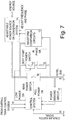
- the arrangement of the systems for performing these functions in a typical train is shown in figure 5 .
- the automatic couplers between vehicles (10) incorporate a switch (20) which is activated during coupling or uncoupling; typically this will be linked to a mechanical latch arrangement which locks vehicles securely together in one position and is released (perhaps by air pressure) to permit uncoupling in the other position. Shunting vehicles together also moves the latch transiently and activates the switch for a short period.
- the outputs from all coupler switches (20) are connected together, via dedicated pins on the electrical connectors of the automatic couplers and wiring through each vehicle to the couplers at each end of the vehicle (or by some multiplexing arrangement with other communication methods giving a similar effect).
- This signal is connected to the control systems (40) of all vehicles capable of supplying hotel power, and receipt of this signal causes a rapid disconnection of hotel power by turning off the switches (50) connecting the power conversion units (60), transformers (70) or other generators to the hotel bus (8).
- the power switches (50) need to turn off the power faster than the time taken between first activating the coupler switches (20) and the hotel bus connectors coming into contact. This can be readily achieved using electronic power switches. If mechanical contactors or relays are used for the power switches, however, achieving switch-off in the few hundred milliseconds it takes to couple vehicles might be a challenge. In this case, an enhancement to the coupler design (not shown in the diagrams) can solve the problem.
- a hotel bus contactor is incorporated into the coupler design, arranged so that the contactor will only close a short delay after successfully coupling to another vehicle.
- the delay can be realised using a spring and damper or a similar mechanical arrangement, arranged so that the time taken for the contactor to close exceeds the time taken for the slowest power switch (50) in use to cut off power. It might be decided to incorporate this feature in the coupler design anyway to avoid live connectors if some other switching or shuttering arrangement does not already provide this facility.
- a coupling or uncoupling event activates the common coupler switch signal (30) and resets the power enable controls in all vehicles supplying hotel power, turning off the power switches (50).
- the common switch signal (30) ceases, coupling or uncoupling operations are complete and this event starts the delay timers (90) in the control systems of each vehicle which can supply hotel power.
- a power sensing circuit (10) in each control system examines the hotel bus to see if power is already being supplied. If not, the power enable control is set which causes that vehicle to switch on its own power to the hotel bus. If power is already on, the power enable control is not set and the corresponding power switch (50) remains in the 'off' state.
- this overall train control system is operating to establish what the new train formation is and the status of various systems within it.
- the exact form and operation of this overall train control system is outside the scope of this invention, but typically it will be distributed in various key vehicles such as locomotives, power cars and driving trailers, operating in a collaborative way by sharing data through dedicated connectors on the automatic couplers and information data bus lines present throughout the train.
- the overall train control system makes some decisions about which vehicles should now be supplying hotel power, and sends commands (11) to the control systems of each vehicle accordingly. That might result in a change of the switch (50) positions to alter the current status of power generation, or it might leave the settings unchanged.
- each train has one or more coaches but only one locomotive and one driving trailer
- traction types might be available, such as diesel and electric locomotives of various sizes, diesel power cars, electric multiple units, etc.
- hotel power generation is sorted out automatically using the different time delays. Then the overall train control system can take different decisions later if necessary. But what happens if more than one traction unit of the SAME type is in the formation?
- both frequency and phase need to be aligned as well as voltage if more than one vehicle is to contribute power to the bus at the same time.
- Diesel traction units, and driving trailers using recycled power are a different matter though: individually they will be generating power at something like the right frequency and at an arbitrary phase relative to each other. Coupling them together would result in overloads and power surges followed by power cut off as overload protection circuits operate. Solving this problem is rather like synchronising power stations on the national grid, on a smaller scale.
- the proposed solution to this problem is to have a 'soft start' approach.
- two diesel power cars are coupled together and after their defined time delay they both try to supply hotel power at the same time, full power is not applied immediately.
- the control system arranges for power from each vehicle to be supplied via a resistance to limit the current to a low level so that overload protection circuits do not trip.
- each control circuit can identify the frequency and phase of the other generator, and can adjust first the frequency and then the phase of its own power generation to be more in alignment.
- the other control circuit is performing similar adjustments in the opposite direction so that the frequency and then the phase of both power generation sources converge. Once the two sources have synchronised, full power is then switched on by the control systems of both vehicles.
- the source of hotel power (14) in the vehicle could be a power conversion system operating from a storage battery (e.g. a driving trailer); a diesel engine and alternator (e.g. a diesel locomotive); a power conversion system operating from a storage battery and a dynamo or rectified alternator in a hybrid drive vehicle (e.g a hybrid drive diesel power car); a power conversion system operating from a DC supply (e.g. a third rail electric multiple unit); or some other source.
- a storage battery e.g. a driving trailer
- a diesel engine and alternator e.g. a diesel locomotive
- a power conversion system operating from a storage battery and a dynamo or rectified alternator in a hybrid drive vehicle e.g a hybrid drive diesel power car
- a power conversion system operating from a DC supply e.g. a third rail electric multiple unit
- it needs to be controllable in frequency and ultimately phase for example via an engine speed control system or using electronic waveform generation.
- the control system (7) operates in the same way as before, but now after the time delay caused by the coupling or uncoupling event, and if power is not present, the main power switch (50) remains off but the soft start power switch (15) is turned on. This connects the power source to the hotel bus (8) via a resistance (16) which limits the current to a low level. If a second power-generating vehicle of the same type is also present in the train formation, it will do the same thing at the same time. The resulting voltage waveform on the hotel bus (8) will be low amplitude (because of the partial load presented by the coaches and the effect of the resistances 16), but its shape will be a representation of the average of the two power sources from the two vehicles coupled together. The waveform comparison circuits (12) compensate for this lower amplitude, and compare the end result with the waveform being generated by the local power source.
- the waveform comparison circuits can then establish whether the frequency of supply being generated locally is higher or lower than the remote source. This result then activates signals to control the power source (14) to alter the frequency to a more similar value to that being generated by the remote source. Naturally the other source performs similar adjustments in the other direction. When the frequencies of the two sources are aligned, finer adjustments are carried out to align the phase of the two sources.
- the overall train control system may choose to activate them via commands (11), initiating the same 'soft start' process.
- commands (11) initiating the same 'soft start' process.
- the sequence is first to turn on that vehicle with full power, then the others with 'soft start' monitor the full amplitude waveform on the hotel bus and adapt their own power generation accordingly before they switch on full power.
Landscapes
- Engineering & Computer Science (AREA)
- Power Engineering (AREA)
- Transportation (AREA)
- Mechanical Engineering (AREA)
- Life Sciences & Earth Sciences (AREA)
- Sustainable Development (AREA)
- Sustainable Energy (AREA)
- Chemical & Material Sciences (AREA)
- Combustion & Propulsion (AREA)
- Electric Propulsion And Braking For Vehicles (AREA)
Claims (8)
- Energiemanagementsystem für eine Zugzusammensetzung, bestehend aus den folgenden Fahrzeugen:einem oder mehreren nicht angetriebenen Fahrzeugen, wobei das Energiemanagementsystem angeordnet ist, um elektrische Energie für Dienste in dem einen oder den mehreren nicht angetriebenen Fahrzeugen bereitzustellen, die über einen Hotelbus (8) zugeführt wird, der angeordnet ist, um koppelbare Fahrzeuge über Verbinder an beiden Enden von jedem Fahrzeug elektrisch parallel zu verbinden;einer Lokomotive oder einem Triebkopf, wobei das Energiemanagementsystem in der Lokomotive oder dem Triebkopf so angeordnet ist, um sowohl Antriebsenergie als auch elektrische Energie für Dienste von einer primären Energiequelle, wie z. B. einem Dieselmotor und Generator oder einer Oberleitung, einem Stromabnehmer und einem Transformator, bereitzustellen;einem Schienenfahrzeug, zur Integration in eine Zugzusammensetzung, wobei das Energiemanagementsystem in dem Schienenfahrzeug angeordnet ist, um regenerative Bremsenergie in elektrische Energie für Dienste zu recyceln, das Energiemanagementsystem in dem Schienenfahrzeug umfassend:einen oder mehrere Antriebe (2) zwischen Rädern und elektrischen Fahrmotoren (1) in einem Fahrzeugkörper, die angeordnet sind, um bei einem regenerativen Bremsen als Generatoren verwendet zu werden;eine Energiemanagementeinheit (3), die angeordnet ist, um die Zufuhr von elektrischer Energie von diesen Motoren zu regulieren;eine Speicherbatterie oder eine andere elektrische Energiespeichervorrichtung oder -system (4), die/das angeordnet ist, um es über die Energiemanagementeinheit (3) Energie von den Motoren (1) aufzunehmen, und eine recycelte Energiequelle bereitstellt;ein Energieumwandlungssystem (5), das angeordnet ist, um Energie von der Speicherbatterie (4) oder der Energiemanagementeinheit (3) in elektrische Energie für Dienste, wie z. B. Heizung, Beleuchtung und Klimatisierung für andere Fahrzeuge der Zugzusammensetzung über den Hotelbus (8) umzuwandeln; undein Steuersystem (7), das angeordnet ist, um die Zufuhr von elektrischer Energie für Dienste von dem Energieumwandlungssystem (5) in diesem Fahrzeug über den Hotelbus (8) zu steuern, um Energie aus Quellen in anderen Fahrzeugen der Zugzusammensetzung, wie z. B. einer Lokomotive, einem Triebkopf, einem Generatorwagen oder einem Stromabnehmerwagen, zu ersetzen oder zu verstärken,wobei das Energiemanagementsystem in dem Schienenfahrzeug angeordnet ist, um Energie aus regenerativem Bremsen in diesem Fahrzeug über den Hotelbus (8) in Strom für Dienste in anderen Fahrzeugen der Zugzusammensetzung zu recyceln, sodass die Gesamtenergieeffizienz der Zugzusammensetzung verbessert wird;wobei die Energiemanagementeinheit (3) angeordnet ist, um das Schalten von Energie (6) zu dem Hotelbus (8) entweder von der primären Energiequelle in einem Fahrzeug oder der recycelten Energiequelle in dem anderen Fahrzeug zu steuern, indem die Steuersysteme des Fahrzeugs, das angeordnet ist, um elektrische Energie von der primären Energiequelle bereitzustellen, und des Fahrzeugs, das angeordnet ist, um elektrische Energie von der recycelten Energiequelle bereitzustellen, koordiniert werden;wobei die Entscheidung, welche Quelle zu verwenden ist, automatisch in Abhängigkeit von vorbestimmten Bedingungen getroffen wird, wie z. B. dem Pegel der recycelten Energie in der Speicherbatterie (4);dadurch gekennzeichnet, dass das Steuersystem (7) von jedem Fahrzeug, das in der Lage ist, Energie zu dem Hotelbus (8) zuzuführen, angeordnet ist, um zu prüfen, ob gerade Energie von einer anderen Quelle zu dem Hotelbus (8) zugeführt wird, bevor es auf eine Anweisung zum Zuführen seiner eigenen Energie zu dem Bus (8) reagiert; undwobei das Energiemanagementsystem in dem Schienenfahrzeug auch angeordnet ist, um Energie für Hoteldienste in den nicht angetriebenen Fahrzeugen der Zugzusammensetzung aufrechtzuerhalten, wenn die Lokomotive oder der Triebkopf von der Zugzusammensetzung getrennt ist.
- Energiemanagementsystem für eine Zugzusammensetzung nach Anspruch 1, wobei jedes Fahrzeug mit Kupplungen (10) ausgerüstet ist, die angeordnet sind, um ein Signal (30) bereitstellen, um anzugeben, wenn ein An- oder Abkuppeln von Fahrzeugen stattfindet;
und wobei das Energiemanagementsystem angeordnet ist, um dieses Signal (30) von einem Koppler eines Fahrzeugs, das in der Lage ist, Energie zu dem Hotelbus (8) zuzuführen, zu empfangen und ein schnelles Abschalten der Energiequelle und einen Neustart der zum Wiedereinschalten erforderlichen Prozesse zu bewirken. - Energiemanagementsystem für eine Zugzusammensetzung nach Anspruch 2, wobei das Steuersystem (40) von jedem Fahrzeug, das in der Lage ist, Energie zu dem Hotelbus (8) zuzuführen, angeordnet ist, um nach Unterbrechen der Energie als Resultat von An- oder Abkupplungsvorgängen eine vorbestimmte Verzögerungszeit abwartet, bevor es versucht, wieder Energie an dem Hotelbus (8) anzuschließen;
wobei der Verzögerungszeit für verschiedene Fahrzeuge oder Fahrzeugtypen unterschiedliche Werte zugewiesen werden, sodass das Fahrzeug mit der kürzesten Verzögerungszeit Vorrang bei der Zuführung von Hotelenergie zu dem Hotelbus (8) erreicht, wenn mehr als ein Fahrzeug, das Energie zuführen kann, in einer neu angeordneten Zugzusammensetzung vorhanden ist. - Energiemanagementsystem für eine Zugzusammensetzung nach Anspruch 3, wobei die Prioritäten für die Erzeugung von Hotelenergie, die entsprechend den Zeitverzögerungen nach Änderungen in einer Zugzusammensetzung wie in Anspruch 3 beschrieben erreicht werden, für eine Zeitspanne gelten, aber später von einem übergeordneten Steuerungsalgorithmus mit anderen Prioritäten außer Kraft gesetzt werden, wenn eine neue Zugzusammensetzung und der Zustand von Systemen innerhalb der neuen Zugzusammensetzung bestimmt wurde.
- Energiemanagementsystem für eine Zugzusammensetzung nach Anspruch 4, wobei der übergeordnete Steueralgorithmus angeordnet ist, um zu bestimmen, ob erlaubt wird, dass mehr als ein Fahrzeug Energie zu dem Hotelbus (8) zuführt, und um die Steuersysteme (40) in diesen Fahrzeugen anzuweisen, ihre Prozesse zum Anschließen ihrer Energie an den Bus zu starten.
- Energiemanagementsystem für eine Zugzusammensetzung nach Anspruch 5, wobei die Steuersysteme (40) von einem oder mehreren Fahrzeugen, die in der Lage sind, Energie zu dem Hotelbus (8) zuzuführen, angeordnet sind, um die Spannung auf dem Bus (8) und auch die Frequenz und die Phase, wenn es sich um Wechselstrom handelt, unter Verwendung eines Sanftstartverfahrens überwachen und die lokalen Energieerzeugungscharakteristiken an diese Parameter anpassen, bevor sie die lokale Energiequelle mit dem Hotelbus (8) verbinden, nachdem sie durch den Steueralgorithmus dazu angewiesen wurden.
- Energiemanagementsystem für eine Zugzusammensetzung nach einem der vorherigen Ansprüche, wobei die Verbindung zwischen den Fahrzeugen der Zugzusammensetzung zur Energieübertragung ein Hotelbus (8) ist, der nur für die maximale, von den Diensten benötigte Energie ausgelegt ist, und keine Bussysteme mit höherer Energie zwischen den Fahrzeugen, wie beispielsweise Bahnstrombusleitungen oder Hochspannungsbusleitungen, verwendet werden.
- Energiemanagementsystem für eine Zugzusammensetzung nach einem der vorherigen Ansprüche, wobei die Zugzusammensetzung angeordnet ist, sodass sie in zwei Abschnitte aufgeteilt werden kann; wobei ein Abschnitt eine Lokomotive oder einen Triebkopf mit einer primären Energiequelle und der andere Abschnitt ein Fahrzeug mit einer recycelten Energiequelle enthält; wobei das Energiemanagementsystem angeordnet ist, um, wenn der Zug aufgeteilt wird, die Hotelenergie für Dienste für beide Abschnitte aufrechtzuerhalten.
Priority Applications (1)
| Application Number | Priority Date | Filing Date | Title |
|---|---|---|---|
| PL12150886T PL2476573T3 (pl) | 2011-01-14 | 2012-01-12 | Układ zarządzania energią dla pociągów ze zmiennymi składami obejmujący hamowanie rekuperacyjne |
Applications Claiming Priority (1)
| Application Number | Priority Date | Filing Date | Title |
|---|---|---|---|
| GB1100616.0A GB2487224B (en) | 2011-01-14 | 2011-01-14 | Energy management system for trains with flexible formations incorporating regenerative braking |
Publications (3)
| Publication Number | Publication Date |
|---|---|
| EP2476573A2 EP2476573A2 (de) | 2012-07-18 |
| EP2476573A3 EP2476573A3 (de) | 2015-11-18 |
| EP2476573B1 true EP2476573B1 (de) | 2021-05-19 |
Family
ID=43736435
Family Applications (1)
| Application Number | Title | Priority Date | Filing Date |
|---|---|---|---|
| EP12150886.5A Active EP2476573B1 (de) | 2011-01-14 | 2012-01-12 | Energieverwaltungssystem für Züge mit flexiblen Formationen mit regenerativer Bremsung |
Country Status (4)
| Country | Link |
|---|---|
| EP (1) | EP2476573B1 (de) |
| ES (1) | ES2872273T3 (de) |
| GB (1) | GB2487224B (de) |
| PL (1) | PL2476573T3 (de) |
Cited By (1)
| Publication number | Priority date | Publication date | Assignee | Title |
|---|---|---|---|---|
| WO2025014372A1 (en) * | 2023-07-12 | 2025-01-16 | Ffwd Rail B.V. | Management of electrical power using a vehicle battery |
Families Citing this family (21)
| Publication number | Priority date | Publication date | Assignee | Title |
|---|---|---|---|---|
| DE102011107628A1 (de) * | 2011-06-30 | 2013-01-03 | Rwe Ag | Ladevorrichtung für elektrofahrzeuge und verfahren zum laden von elektrofahrzeugen |
| KR101635331B1 (ko) * | 2012-08-14 | 2016-07-08 | 미쓰비시덴키 가부시키가이샤 | 열차 정보 관리 장치 및 기기 제어 방법 |
| LT3007925T (lt) | 2013-06-14 | 2019-07-25 | Hedgehog Applications B.V. | Geležinkelio transporto priemonių regeneratyvinės stabdymo energijos panaudojimo būdai ir sistema |
| US9100838B2 (en) | 2013-07-29 | 2015-08-04 | Electro-Motive Diesel, Inc. | Rail system having a wired communication zone |
| JP6228042B2 (ja) * | 2014-03-07 | 2017-11-08 | 株式会社日立製作所 | 駆動制御システムおよび駆動制御システムを備えた移動体 |
| DE102015211948A1 (de) * | 2015-06-26 | 2016-12-29 | Siemens Aktiengesellschaft | Verfahren zum Steuern eines Energieflusses in einem Energienetzwerk, Teilnehmer, Leiteinrichtung und Energienetzwerk |
| CN106314181B (zh) * | 2016-09-08 | 2018-12-25 | 武汉杜曼智能科技有限公司 | 一种电动车辆在线快速充电系统和充电方法 |
| CN109383298B (zh) * | 2017-08-04 | 2021-09-24 | 中车大同电力机车有限公司 | 一种城市有轨电车运营端自动转换方法 |
| CN109428331A (zh) * | 2017-08-24 | 2019-03-05 | 株洲中车时代电气股份有限公司 | 一种牵引变电所用综合能源装置及其控制方法 |
| CN109795518B (zh) | 2017-11-17 | 2021-03-19 | 中车唐山机车车辆有限公司 | 一种轨道列车制动控制系统及列车 |
| ES2997158T3 (en) * | 2018-10-03 | 2025-02-14 | Schweizerische Bundesbahnen Sbb | Brake system for a rail vehicle |
| RU190756U1 (ru) * | 2019-01-22 | 2019-07-11 | Общество с ограниченной ответственностью "Промтехмонтаж" (ООО "ПТМ") | Устройство электроснабжения высоковольтных потребителей пассажирского вагона |
| CN110395299B (zh) * | 2019-07-29 | 2021-08-06 | 交控科技股份有限公司 | 城市轨道交通中列车制动能量利用方法 |
| CN110588447A (zh) * | 2019-09-04 | 2019-12-20 | 中车青岛四方机车车辆股份有限公司 | 一种轨道车辆直流电源管理系统及轨道车辆 |
| RU197557U1 (ru) * | 2020-02-14 | 2020-05-13 | Общество с ограниченной ответственностью "Балтийские кондиционеры" | Шкаф управления комплектом электрооборудования пассажирского вагона |
| CN111806235B (zh) * | 2020-07-22 | 2022-06-07 | 西南交通大学 | 一种车地一体多功能应急储能供电系统及其控制方法 |
| GB2600408B (en) | 2020-10-27 | 2024-04-03 | Ritchie Kinghorn John | Extendable coupler |
| CN112406636B (zh) * | 2020-11-04 | 2022-01-28 | 西南交通大学 | 一种多所协同的再生制动能量利用系统及其控制方法 |
| GB2603129A (en) * | 2021-01-25 | 2022-08-03 | Bombardier Transp Gmbh | Method for managing power consumption of a railway vehicle, and railway vehicle with improved power consumption management |
| GB2612591B (en) | 2021-11-03 | 2024-05-29 | Ritchie Kinghorn John | Interface system |
| CN119239662B (zh) * | 2024-10-29 | 2025-10-17 | 中车青岛四方机车车辆股份有限公司 | 重联列车的受电弓重联控制电路、方法及重联列车 |
Citations (1)
| Publication number | Priority date | Publication date | Assignee | Title |
|---|---|---|---|---|
| US20080223250A1 (en) * | 2007-03-13 | 2008-09-18 | Bachman Eric C | System and method for providing head end power for use in passenger train sets |
Family Cites Families (5)
| Publication number | Priority date | Publication date | Assignee | Title |
|---|---|---|---|---|
| US4892204A (en) * | 1988-06-02 | 1990-01-09 | General Signal Corporation | Automatic coupler control system |
| US20060005739A1 (en) * | 2001-03-27 | 2006-01-12 | Kumar Ajith K | Railroad system comprising railroad vehicle with energy regeneration |
| US20060005736A1 (en) * | 2001-03-27 | 2006-01-12 | General Electric Company | Hybrid energy off highway vehicle electric power management system and method |
| US7701077B2 (en) * | 2004-07-23 | 2010-04-20 | General Electric Company | Secondary power for critical loads for railroad |
| US20080000381A1 (en) * | 2006-05-24 | 2008-01-03 | Bartley Thomas L | Rail car braking regeneration and propulsion system and method |
-
2011
- 2011-01-14 GB GB1100616.0A patent/GB2487224B/en active Active
-
2012
- 2012-01-12 PL PL12150886T patent/PL2476573T3/pl unknown
- 2012-01-12 ES ES12150886T patent/ES2872273T3/es active Active
- 2012-01-12 EP EP12150886.5A patent/EP2476573B1/de active Active
Patent Citations (1)
| Publication number | Priority date | Publication date | Assignee | Title |
|---|---|---|---|---|
| US20080223250A1 (en) * | 2007-03-13 | 2008-09-18 | Bachman Eric C | System and method for providing head end power for use in passenger train sets |
Cited By (2)
| Publication number | Priority date | Publication date | Assignee | Title |
|---|---|---|---|---|
| WO2025014372A1 (en) * | 2023-07-12 | 2025-01-16 | Ffwd Rail B.V. | Management of electrical power using a vehicle battery |
| NL2035359B1 (en) * | 2023-07-12 | 2025-01-27 | Ffwd Rail B V | Management of Electrical Power Using a Vehicle Battery |
Also Published As
| Publication number | Publication date |
|---|---|
| GB201100616D0 (en) | 2011-03-02 |
| PL2476573T3 (pl) | 2021-09-13 |
| GB2487224A (en) | 2012-07-18 |
| EP2476573A2 (de) | 2012-07-18 |
| EP2476573A3 (de) | 2015-11-18 |
| ES2872273T3 (es) | 2021-11-02 |
| GB2487224B (en) | 2015-08-12 |
Similar Documents
| Publication | Publication Date | Title |
|---|---|---|
| EP2476573B1 (de) | Energieverwaltungssystem für Züge mit flexiblen Formationen mit regenerativer Bremsung | |
| JP5801999B2 (ja) | 鉄道用車上電気機器を搭載した鉄道車両の編成列車 | |
| EP1763451B1 (de) | Energiespeichersystem und verfahren für hybridantrieb | |
| EP3007925B1 (de) | Verfahren und system zur verwendung von regenerativer bremsenergie von schienenfahrzeugen | |
| JP7698656B2 (ja) | エネルギー管理システムを含む電気牽引を有する車両及びこの種の電気牽引を有する車両においてエネルギーを管理する方法 | |
| CN101837740B (zh) | 在车站之间线路上设置供电设备的铁路系统 | |
| US20200207377A1 (en) | Railway power system and associated method | |
| TW201010883A (en) | Power supply controlling system and power supply controlling method | |
| EP3450244A1 (de) | Elektrisches schienenfahrzeugantriebssystem und fahrzeugantriebsverfahren | |
| US20150027837A1 (en) | Rail system having an energy exchange station | |
| US20200207376A1 (en) | Power system and associated method | |
| CN110733515A (zh) | 用于轨道车辆的至少一个储能器充能的方法和装置 | |
| CN109987002A (zh) | 一种有轨电车的供电控制方法、牵引变流器及有轨电车 | |
| JP5851925B2 (ja) | 電気鉄道車両の駆動システム | |
| JP2004304989A (ja) | エネルギ送受制御システム及び鉄道車両駆動システム、並びに鉄道車両 | |
| CN110719867A (zh) | 缆线牵引的运输设备和用于操作缆线牵引的运输设备的方法 | |
| CN115972991A (zh) | 一种双源动车组过分相列供保持及牵引平稳性控制方法 | |
| JP7441374B2 (ja) | 電気車および電気車システム | |
| JP2005051891A (ja) | き電装置、列車編成及び被牽引車 | |
| KR20260015069A (ko) | 철도차량의 듀얼모터 추진 장치 및 이의 제어방법 | |
| EP4640473A1 (de) | Traktionssystem für ein fahrzeug mit elektrischer traktion | |
| Gay et al. | On-board electrically peaking drive train for electric railway vehicles | |
| CN118372855A (zh) | 一种动力牵引系统及列车 | |
| CN116620334A (zh) | 重联机车及其牵引供电电路、控制方法 | |
| HK1220669B (en) | Method and system for utilization of regenerative braking energy of rail vehicles |
Legal Events
| Date | Code | Title | Description |
|---|---|---|---|
| PUAI | Public reference made under article 153(3) epc to a published international application that has entered the european phase |
Free format text: ORIGINAL CODE: 0009012 |
|
| AK | Designated contracting states |
Kind code of ref document: A2 Designated state(s): AL AT BE BG CH CY CZ DE DK EE ES FI FR GB GR HR HU IE IS IT LI LT LU LV MC MK MT NL NO PL PT RO RS SE SI SK SM TR |
|
| AX | Request for extension of the european patent |
Extension state: BA ME |
|
| PUAL | Search report despatched |
Free format text: ORIGINAL CODE: 0009013 |
|
| AK | Designated contracting states |
Kind code of ref document: A3 Designated state(s): AL AT BE BG CH CY CZ DE DK EE ES FI FR GB GR HR HU IE IS IT LI LT LU LV MC MK MT NL NO PL PT RO RS SE SI SK SM TR |
|
| AX | Request for extension of the european patent |
Extension state: BA ME |
|
| RIC1 | Information provided on ipc code assigned before grant |
Ipc: B60L 1/12 20060101ALI20151012BHEP Ipc: B60L 1/16 20060101ALI20151012BHEP Ipc: B60L 1/00 20060101ALI20151012BHEP Ipc: B60L 7/10 20060101ALI20151012BHEP Ipc: B60L 11/18 20060101ALI20151012BHEP Ipc: B60L 1/10 20060101AFI20151012BHEP Ipc: B60L 7/18 20060101ALI20151012BHEP Ipc: H02J 3/38 20060101ALI20151012BHEP Ipc: B60L 1/04 20060101ALI20151012BHEP Ipc: B60L 3/00 20060101ALI20151012BHEP |
|
| 17P | Request for examination filed |
Effective date: 20160516 |
|
| RBV | Designated contracting states (corrected) |
Designated state(s): AL AT BE BG CH CY CZ DE DK EE ES FI FR GB GR HR HU IE IS IT LI LT LU LV MC MK MT NL NO PL PT RO RS SE SI SK SM TR |
|
| STAA | Information on the status of an ep patent application or granted ep patent |
Free format text: STATUS: EXAMINATION IS IN PROGRESS |
|
| 17Q | First examination report despatched |
Effective date: 20191115 |
|
| RIC1 | Information provided on ipc code assigned before grant |
Ipc: B60L 1/04 20060101ALI20201001BHEP Ipc: H02J 3/38 20060101ALI20201001BHEP Ipc: B60L 7/18 20060101ALI20201001BHEP Ipc: B60L 3/00 20190101ALI20201001BHEP Ipc: B60L 1/12 20060101ALI20201001BHEP Ipc: B60L 1/16 20060101ALI20201001BHEP Ipc: B60L 1/10 20060101AFI20201001BHEP Ipc: B60L 1/00 20060101ALI20201001BHEP |
|
| GRAP | Despatch of communication of intention to grant a patent |
Free format text: ORIGINAL CODE: EPIDOSNIGR1 |
|
| STAA | Information on the status of an ep patent application or granted ep patent |
Free format text: STATUS: GRANT OF PATENT IS INTENDED |
|
| INTG | Intention to grant announced |
Effective date: 20201218 |
|
| GRAJ | Information related to disapproval of communication of intention to grant by the applicant or resumption of examination proceedings by the epo deleted |
Free format text: ORIGINAL CODE: EPIDOSDIGR1 |
|
| GRAL | Information related to payment of fee for publishing/printing deleted |
Free format text: ORIGINAL CODE: EPIDOSDIGR3 |
|
| GRAS | Grant fee paid |
Free format text: ORIGINAL CODE: EPIDOSNIGR3 |
|
| STAA | Information on the status of an ep patent application or granted ep patent |
Free format text: STATUS: EXAMINATION IS IN PROGRESS |
|
| GRAP | Despatch of communication of intention to grant a patent |
Free format text: ORIGINAL CODE: EPIDOSNIGR1 |
|
| STAA | Information on the status of an ep patent application or granted ep patent |
Free format text: STATUS: GRANT OF PATENT IS INTENDED |
|
| RBV | Designated contracting states (corrected) |
Designated state(s): AL AT BE BG CH CY CZ DE DK EE ES FI FR GR HR HU IE IS IT LI LT LU LV MC MK MT NL NO PL PT RO RS SE SI SK SM TR |
|
| INTC | Intention to grant announced (deleted) | ||
| GRAA | (expected) grant |
Free format text: ORIGINAL CODE: 0009210 |
|
| STAA | Information on the status of an ep patent application or granted ep patent |
Free format text: STATUS: THE PATENT HAS BEEN GRANTED |
|
| INTG | Intention to grant announced |
Effective date: 20210326 |
|
| AK | Designated contracting states |
Kind code of ref document: B1 Designated state(s): AL AT BE BG CH CY CZ DE DK EE ES FI FR GR HR HU IE IS IT LI LT LU LV MC MK MT NL NO PL PT RO RS SE SI SK SM TR |
|
| REG | Reference to a national code |
Ref country code: CH Ref legal event code: EP |
|
| REG | Reference to a national code |
Ref country code: DE Ref legal event code: R096 Ref document number: 602012075587 Country of ref document: DE |
|
| REG | Reference to a national code |
Ref country code: AT Ref legal event code: REF Ref document number: 1393659 Country of ref document: AT Kind code of ref document: T Effective date: 20210615 |
|
| REG | Reference to a national code |
Ref country code: IE Ref legal event code: FG4D |
|
| REG | Reference to a national code |
Ref country code: LT Ref legal event code: MG9D |
|
| REG | Reference to a national code |
Ref country code: NL Ref legal event code: MP Effective date: 20210519 |
|
| PG25 | Lapsed in a contracting state [announced via postgrant information from national office to epo] |
Ref country code: LT Free format text: LAPSE BECAUSE OF FAILURE TO SUBMIT A TRANSLATION OF THE DESCRIPTION OR TO PAY THE FEE WITHIN THE PRESCRIBED TIME-LIMIT Effective date: 20210519 Ref country code: FI Free format text: LAPSE BECAUSE OF FAILURE TO SUBMIT A TRANSLATION OF THE DESCRIPTION OR TO PAY THE FEE WITHIN THE PRESCRIBED TIME-LIMIT Effective date: 20210519 Ref country code: HR Free format text: LAPSE BECAUSE OF FAILURE TO SUBMIT A TRANSLATION OF THE DESCRIPTION OR TO PAY THE FEE WITHIN THE PRESCRIBED TIME-LIMIT Effective date: 20210519 Ref country code: BG Free format text: LAPSE BECAUSE OF FAILURE TO SUBMIT A TRANSLATION OF THE DESCRIPTION OR TO PAY THE FEE WITHIN THE PRESCRIBED TIME-LIMIT Effective date: 20210819 |
|
| REG | Reference to a national code |
Ref country code: ES Ref legal event code: FG2A Ref document number: 2872273 Country of ref document: ES Kind code of ref document: T3 Effective date: 20211102 |
|
| PG25 | Lapsed in a contracting state [announced via postgrant information from national office to epo] |
Ref country code: RS Free format text: LAPSE BECAUSE OF FAILURE TO SUBMIT A TRANSLATION OF THE DESCRIPTION OR TO PAY THE FEE WITHIN THE PRESCRIBED TIME-LIMIT Effective date: 20210519 Ref country code: SE Free format text: LAPSE BECAUSE OF FAILURE TO SUBMIT A TRANSLATION OF THE DESCRIPTION OR TO PAY THE FEE WITHIN THE PRESCRIBED TIME-LIMIT Effective date: 20210519 Ref country code: IS Free format text: LAPSE BECAUSE OF FAILURE TO SUBMIT A TRANSLATION OF THE DESCRIPTION OR TO PAY THE FEE WITHIN THE PRESCRIBED TIME-LIMIT Effective date: 20210919 Ref country code: GR Free format text: LAPSE BECAUSE OF FAILURE TO SUBMIT A TRANSLATION OF THE DESCRIPTION OR TO PAY THE FEE WITHIN THE PRESCRIBED TIME-LIMIT Effective date: 20210820 Ref country code: LV Free format text: LAPSE BECAUSE OF FAILURE TO SUBMIT A TRANSLATION OF THE DESCRIPTION OR TO PAY THE FEE WITHIN THE PRESCRIBED TIME-LIMIT Effective date: 20210519 Ref country code: PT Free format text: LAPSE BECAUSE OF FAILURE TO SUBMIT A TRANSLATION OF THE DESCRIPTION OR TO PAY THE FEE WITHIN THE PRESCRIBED TIME-LIMIT Effective date: 20210920 Ref country code: NO Free format text: LAPSE BECAUSE OF FAILURE TO SUBMIT A TRANSLATION OF THE DESCRIPTION OR TO PAY THE FEE WITHIN THE PRESCRIBED TIME-LIMIT Effective date: 20210819 |
|
| PG25 | Lapsed in a contracting state [announced via postgrant information from national office to epo] |
Ref country code: NL Free format text: LAPSE BECAUSE OF FAILURE TO SUBMIT A TRANSLATION OF THE DESCRIPTION OR TO PAY THE FEE WITHIN THE PRESCRIBED TIME-LIMIT Effective date: 20210519 |
|
| PG25 | Lapsed in a contracting state [announced via postgrant information from national office to epo] |
Ref country code: DK Free format text: LAPSE BECAUSE OF FAILURE TO SUBMIT A TRANSLATION OF THE DESCRIPTION OR TO PAY THE FEE WITHIN THE PRESCRIBED TIME-LIMIT Effective date: 20210519 Ref country code: EE Free format text: LAPSE BECAUSE OF FAILURE TO SUBMIT A TRANSLATION OF THE DESCRIPTION OR TO PAY THE FEE WITHIN THE PRESCRIBED TIME-LIMIT Effective date: 20210519 Ref country code: SM Free format text: LAPSE BECAUSE OF FAILURE TO SUBMIT A TRANSLATION OF THE DESCRIPTION OR TO PAY THE FEE WITHIN THE PRESCRIBED TIME-LIMIT Effective date: 20210519 Ref country code: SK Free format text: LAPSE BECAUSE OF FAILURE TO SUBMIT A TRANSLATION OF THE DESCRIPTION OR TO PAY THE FEE WITHIN THE PRESCRIBED TIME-LIMIT Effective date: 20210519 Ref country code: RO Free format text: LAPSE BECAUSE OF FAILURE TO SUBMIT A TRANSLATION OF THE DESCRIPTION OR TO PAY THE FEE WITHIN THE PRESCRIBED TIME-LIMIT Effective date: 20210519 |
|
| REG | Reference to a national code |
Ref country code: DE Ref legal event code: R097 Ref document number: 602012075587 Country of ref document: DE |
|
| PLBE | No opposition filed within time limit |
Free format text: ORIGINAL CODE: 0009261 |
|
| STAA | Information on the status of an ep patent application or granted ep patent |
Free format text: STATUS: NO OPPOSITION FILED WITHIN TIME LIMIT |
|
| 26N | No opposition filed |
Effective date: 20220222 |
|
| PG25 | Lapsed in a contracting state [announced via postgrant information from national office to epo] |
Ref country code: IS Free format text: LAPSE BECAUSE OF FAILURE TO SUBMIT A TRANSLATION OF THE DESCRIPTION OR TO PAY THE FEE WITHIN THE PRESCRIBED TIME-LIMIT Effective date: 20210919 Ref country code: AL Free format text: LAPSE BECAUSE OF FAILURE TO SUBMIT A TRANSLATION OF THE DESCRIPTION OR TO PAY THE FEE WITHIN THE PRESCRIBED TIME-LIMIT Effective date: 20210519 |
|
| PG25 | Lapsed in a contracting state [announced via postgrant information from national office to epo] |
Ref country code: MC Free format text: LAPSE BECAUSE OF FAILURE TO SUBMIT A TRANSLATION OF THE DESCRIPTION OR TO PAY THE FEE WITHIN THE PRESCRIBED TIME-LIMIT Effective date: 20210519 |
|
| PG25 | Lapsed in a contracting state [announced via postgrant information from national office to epo] |
Ref country code: LU Free format text: LAPSE BECAUSE OF NON-PAYMENT OF DUE FEES Effective date: 20220112 |
|
| REG | Reference to a national code |
Ref country code: AT Ref legal event code: UEP Ref document number: 1393659 Country of ref document: AT Kind code of ref document: T Effective date: 20210519 |
|
| PG25 | Lapsed in a contracting state [announced via postgrant information from national office to epo] |
Ref country code: IE Free format text: LAPSE BECAUSE OF NON-PAYMENT OF DUE FEES Effective date: 20220112 |
|
| P01 | Opt-out of the competence of the unified patent court (upc) registered |
Effective date: 20230514 |
|
| PG25 | Lapsed in a contracting state [announced via postgrant information from national office to epo] |
Ref country code: HU Free format text: LAPSE BECAUSE OF FAILURE TO SUBMIT A TRANSLATION OF THE DESCRIPTION OR TO PAY THE FEE WITHIN THE PRESCRIBED TIME-LIMIT; INVALID AB INITIO Effective date: 20120112 |
|
| PGFP | Annual fee paid to national office [announced via postgrant information from national office to epo] |
Ref country code: AT Payment date: 20240110 Year of fee payment: 13 |
|
| PG25 | Lapsed in a contracting state [announced via postgrant information from national office to epo] |
Ref country code: MK Free format text: LAPSE BECAUSE OF FAILURE TO SUBMIT A TRANSLATION OF THE DESCRIPTION OR TO PAY THE FEE WITHIN THE PRESCRIBED TIME-LIMIT Effective date: 20210519 Ref country code: CY Free format text: LAPSE BECAUSE OF FAILURE TO SUBMIT A TRANSLATION OF THE DESCRIPTION OR TO PAY THE FEE WITHIN THE PRESCRIBED TIME-LIMIT Effective date: 20210519 |
|
| PGFP | Annual fee paid to national office [announced via postgrant information from national office to epo] |
Ref country code: CZ Payment date: 20240109 Year of fee payment: 13 |
|
| PG25 | Lapsed in a contracting state [announced via postgrant information from national office to epo] |
Ref country code: TR Free format text: LAPSE BECAUSE OF FAILURE TO SUBMIT A TRANSLATION OF THE DESCRIPTION OR TO PAY THE FEE WITHIN THE PRESCRIBED TIME-LIMIT Effective date: 20210519 |
|
| PG25 | Lapsed in a contracting state [announced via postgrant information from national office to epo] |
Ref country code: MT Free format text: LAPSE BECAUSE OF FAILURE TO SUBMIT A TRANSLATION OF THE DESCRIPTION OR TO PAY THE FEE WITHIN THE PRESCRIBED TIME-LIMIT Effective date: 20210519 |
|
| PGFP | Annual fee paid to national office [announced via postgrant information from national office to epo] |
Ref country code: DE Payment date: 20250103 Year of fee payment: 14 |
|
| PGFP | Annual fee paid to national office [announced via postgrant information from national office to epo] |
Ref country code: ES Payment date: 20250205 Year of fee payment: 14 |
|
| PGFP | Annual fee paid to national office [announced via postgrant information from national office to epo] |
Ref country code: CH Payment date: 20250201 Year of fee payment: 14 |
|
| PGFP | Annual fee paid to national office [announced via postgrant information from national office to epo] |
Ref country code: IT Payment date: 20250122 Year of fee payment: 14 |
|
| REG | Reference to a national code |
Ref country code: AT Ref legal event code: MM01 Ref document number: 1393659 Country of ref document: AT Kind code of ref document: T Effective date: 20250112 |
|
| PG25 | Lapsed in a contracting state [announced via postgrant information from national office to epo] |
Ref country code: AT Free format text: LAPSE BECAUSE OF NON-PAYMENT OF DUE FEES Effective date: 20250112 |
|
| PG25 | Lapsed in a contracting state [announced via postgrant information from national office to epo] |
Ref country code: CZ Free format text: LAPSE BECAUSE OF NON-PAYMENT OF DUE FEES Effective date: 20250112 |
|
| PGFP | Annual fee paid to national office [announced via postgrant information from national office to epo] |
Ref country code: FR Payment date: 20251204 Year of fee payment: 15 |
|
| PGFP | Annual fee paid to national office [announced via postgrant information from national office to epo] |
Ref country code: BE Payment date: 20251204 Year of fee payment: 15 |
|
| PGFP | Annual fee paid to national office [announced via postgrant information from national office to epo] |
Ref country code: PL Payment date: 20251202 Year of fee payment: 15 |
|
| REG | Reference to a national code |
Ref country code: CH Ref legal event code: U11 Free format text: ST27 STATUS EVENT CODE: U-0-0-U10-U11 (AS PROVIDED BY THE NATIONAL OFFICE) Effective date: 20260201 |