EP2476452A1 - Device for insertion into tube - Google Patents
Device for insertion into tube Download PDFInfo
- Publication number
- EP2476452A1 EP2476452A1 EP10815229A EP10815229A EP2476452A1 EP 2476452 A1 EP2476452 A1 EP 2476452A1 EP 10815229 A EP10815229 A EP 10815229A EP 10815229 A EP10815229 A EP 10815229A EP 2476452 A1 EP2476452 A1 EP 2476452A1
- Authority
- EP
- European Patent Office
- Prior art keywords
- shaft
- flexible shaft
- spirally
- hole
- distal end
- Prior art date
- Legal status (The legal status is an assumption and is not a legal conclusion. Google has not performed a legal analysis and makes no representation as to the accuracy of the status listed.)
- Granted
Links
- 238000003780 insertion Methods 0.000 title claims abstract description 147
- 230000037431 insertion Effects 0.000 title claims abstract description 141
- 238000004804 winding Methods 0.000 claims abstract description 16
- 239000002775 capsule Substances 0.000 claims description 64
- 238000005452 bending Methods 0.000 claims description 38
- 238000010586 diagram Methods 0.000 description 22
- 230000007246 mechanism Effects 0.000 description 21
- 210000003708 urethra Anatomy 0.000 description 12
- 210000002429 large intestine Anatomy 0.000 description 11
- 230000005540 biological transmission Effects 0.000 description 10
- 210000003384 transverse colon Anatomy 0.000 description 9
- 229910052751 metal Inorganic materials 0.000 description 8
- 239000002184 metal Substances 0.000 description 8
- 229920005989 resin Polymers 0.000 description 8
- 239000011347 resin Substances 0.000 description 8
- XLYOFNOQVPJJNP-UHFFFAOYSA-N water Substances O XLYOFNOQVPJJNP-UHFFFAOYSA-N 0.000 description 8
- 238000005286 illumination Methods 0.000 description 7
- 238000004891 communication Methods 0.000 description 6
- 230000008878 coupling Effects 0.000 description 6
- 238000010168 coupling process Methods 0.000 description 6
- 238000005859 coupling reaction Methods 0.000 description 6
- 238000004026 adhesive bonding Methods 0.000 description 5
- 230000003287 optical effect Effects 0.000 description 4
- 239000011248 coating agent Substances 0.000 description 3
- 238000000576 coating method Methods 0.000 description 3
- 238000012545 processing Methods 0.000 description 3
- 239000010935 stainless steel Substances 0.000 description 3
- 229910001220 stainless steel Inorganic materials 0.000 description 3
- 210000002784 stomach Anatomy 0.000 description 3
- 238000003466 welding Methods 0.000 description 3
- 210000000436 anus Anatomy 0.000 description 2
- 210000004204 blood vessel Anatomy 0.000 description 2
- 229920001971 elastomer Polymers 0.000 description 2
- 210000001035 gastrointestinal tract Anatomy 0.000 description 2
- 210000000936 intestine Anatomy 0.000 description 2
- 230000014759 maintenance of location Effects 0.000 description 2
- 229910001000 nickel titanium Inorganic materials 0.000 description 2
- 238000005476 soldering Methods 0.000 description 2
- 229920002803 thermoplastic polyurethane Polymers 0.000 description 2
- 210000003437 trachea Anatomy 0.000 description 2
- 210000002700 urine Anatomy 0.000 description 2
- 229910000838 Al alloy Inorganic materials 0.000 description 1
- 206010028980 Neoplasm Diseases 0.000 description 1
- 229920006311 Urethane elastomer Polymers 0.000 description 1
- HZEWFHLRYVTOIW-UHFFFAOYSA-N [Ti].[Ni] Chemical compound [Ti].[Ni] HZEWFHLRYVTOIW-UHFFFAOYSA-N 0.000 description 1
- 229910045601 alloy Inorganic materials 0.000 description 1
- 239000000956 alloy Substances 0.000 description 1
- 230000000903 blocking effect Effects 0.000 description 1
- 210000001124 body fluid Anatomy 0.000 description 1
- 239000010839 body fluid Substances 0.000 description 1
- 201000011510 cancer Diseases 0.000 description 1
- 230000008859 change Effects 0.000 description 1
- 238000006243 chemical reaction Methods 0.000 description 1
- 210000001072 colon Anatomy 0.000 description 1
- 238000001514 detection method Methods 0.000 description 1
- 239000012530 fluid Substances 0.000 description 1
- 229920001973 fluoroelastomer Polymers 0.000 description 1
- 238000000034 method Methods 0.000 description 1
- 238000012986 modification Methods 0.000 description 1
- 230000004048 modification Effects 0.000 description 1
- 210000000214 mouth Anatomy 0.000 description 1
- 229920000728 polyester Polymers 0.000 description 1
- 230000002265 prevention Effects 0.000 description 1
- 230000002040 relaxant effect Effects 0.000 description 1
- 210000000813 small intestine Anatomy 0.000 description 1
- 239000007921 spray Substances 0.000 description 1
- 229920005992 thermoplastic resin Polymers 0.000 description 1
- WFKWXMTUELFFGS-UHFFFAOYSA-N tungsten Chemical compound [W] WFKWXMTUELFFGS-UHFFFAOYSA-N 0.000 description 1
- 229910052721 tungsten Inorganic materials 0.000 description 1
- 239000010937 tungsten Substances 0.000 description 1
Images


Classifications
-
- A—HUMAN NECESSITIES
- A61—MEDICAL OR VETERINARY SCIENCE; HYGIENE
- A61B—DIAGNOSIS; SURGERY; IDENTIFICATION
- A61B1/00—Instruments for performing medical examinations of the interior of cavities or tubes of the body by visual or photographical inspection, e.g. endoscopes; Illuminating arrangements therefor
- A61B1/31—Instruments for performing medical examinations of the interior of cavities or tubes of the body by visual or photographical inspection, e.g. endoscopes; Illuminating arrangements therefor for the rectum, e.g. proctoscopes, sigmoidoscopes, colonoscopes
-
- A—HUMAN NECESSITIES
- A61—MEDICAL OR VETERINARY SCIENCE; HYGIENE
- A61B—DIAGNOSIS; SURGERY; IDENTIFICATION
- A61B1/00—Instruments for performing medical examinations of the interior of cavities or tubes of the body by visual or photographical inspection, e.g. endoscopes; Illuminating arrangements therefor
- A61B1/00147—Holding or positioning arrangements
- A61B1/00148—Holding or positioning arrangements using anchoring means
-
- A—HUMAN NECESSITIES
- A61—MEDICAL OR VETERINARY SCIENCE; HYGIENE
- A61B—DIAGNOSIS; SURGERY; IDENTIFICATION
- A61B1/00—Instruments for performing medical examinations of the interior of cavities or tubes of the body by visual or photographical inspection, e.g. endoscopes; Illuminating arrangements therefor
- A61B1/00147—Holding or positioning arrangements
- A61B1/00156—Holding or positioning arrangements using self propulsion
-
- A—HUMAN NECESSITIES
- A61—MEDICAL OR VETERINARY SCIENCE; HYGIENE
- A61B—DIAGNOSIS; SURGERY; IDENTIFICATION
- A61B1/00—Instruments for performing medical examinations of the interior of cavities or tubes of the body by visual or photographical inspection, e.g. endoscopes; Illuminating arrangements therefor
- A61B1/00147—Holding or positioning arrangements
- A61B1/0016—Holding or positioning arrangements using motor drive units
-
- A—HUMAN NECESSITIES
- A61—MEDICAL OR VETERINARY SCIENCE; HYGIENE
- A61B—DIAGNOSIS; SURGERY; IDENTIFICATION
- A61B1/00—Instruments for performing medical examinations of the interior of cavities or tubes of the body by visual or photographical inspection, e.g. endoscopes; Illuminating arrangements therefor
- A61B1/273—Instruments for performing medical examinations of the interior of cavities or tubes of the body by visual or photographical inspection, e.g. endoscopes; Illuminating arrangements therefor for the upper alimentary canal, e.g. oesophagoscopes, gastroscopes
- A61B1/2736—Gastroscopes
-
- A—HUMAN NECESSITIES
- A61—MEDICAL OR VETERINARY SCIENCE; HYGIENE
- A61M—DEVICES FOR INTRODUCING MEDIA INTO, OR ONTO, THE BODY; DEVICES FOR TRANSDUCING BODY MEDIA OR FOR TAKING MEDIA FROM THE BODY; DEVICES FOR PRODUCING OR ENDING SLEEP OR STUPOR
- A61M25/00—Catheters; Hollow probes
- A61M25/01—Introducing, guiding, advancing, emplacing or holding catheters
- A61M25/0105—Steering means as part of the catheter or advancing means; Markers for positioning
- A61M25/0116—Steering means as part of the catheter or advancing means; Markers for positioning self-propelled, e.g. autonomous robots
-
- A—HUMAN NECESSITIES
- A61—MEDICAL OR VETERINARY SCIENCE; HYGIENE
- A61B—DIAGNOSIS; SURGERY; IDENTIFICATION
- A61B1/00—Instruments for performing medical examinations of the interior of cavities or tubes of the body by visual or photographical inspection, e.g. endoscopes; Illuminating arrangements therefor
- A61B1/005—Flexible endoscopes
- A61B1/0051—Flexible endoscopes with controlled bending of insertion part
-
- A—HUMAN NECESSITIES
- A61—MEDICAL OR VETERINARY SCIENCE; HYGIENE
- A61B—DIAGNOSIS; SURGERY; IDENTIFICATION
- A61B1/00—Instruments for performing medical examinations of the interior of cavities or tubes of the body by visual or photographical inspection, e.g. endoscopes; Illuminating arrangements therefor
- A61B1/06—Instruments for performing medical examinations of the interior of cavities or tubes of the body by visual or photographical inspection, e.g. endoscopes; Illuminating arrangements therefor with illuminating arrangements
- A61B1/0661—Endoscope light sources
- A61B1/0669—Endoscope light sources at proximal end of an endoscope
-
- A—HUMAN NECESSITIES
- A61—MEDICAL OR VETERINARY SCIENCE; HYGIENE
- A61B—DIAGNOSIS; SURGERY; IDENTIFICATION
- A61B1/00—Instruments for performing medical examinations of the interior of cavities or tubes of the body by visual or photographical inspection, e.g. endoscopes; Illuminating arrangements therefor
- A61B1/12—Instruments for performing medical examinations of the interior of cavities or tubes of the body by visual or photographical inspection, e.g. endoscopes; Illuminating arrangements therefor with cooling or rinsing arrangements
- A61B1/126—Instruments for performing medical examinations of the interior of cavities or tubes of the body by visual or photographical inspection, e.g. endoscopes; Illuminating arrangements therefor with cooling or rinsing arrangements provided with means for cleaning in-use
Definitions
- the present invention relates to an intraductal insertion device which can advance and retract an insertion portion in a duct using thrust developed by a thrust generating section.
- an intraductal insertion device such as a catheter is inserted directly into the urethra or the like.
- an elongated insertion portion of an endoscope is inserted, for example, into the stomach through the oral cavity, or into the large intestine or the like through the anus.
- the endoscope is equipped with a bending portion on a distal end side of the elongated insertion portion, where the bending portion is configured by linking bending pieces together, for example, to perform bending operation in up-and-down and left-to-right directions.
- the bending portion is configured to perform bending operation when a surgeon operates, for example, a bending knob provided in an operation section and thereby advances and retracts an operation wire connected to the bending pieces.
- US patent No. 7,048,717 discloses an endoscope insertion aid device and the like equipped with a spiral structure.
- the spiral structural portion and large intestine walls form a relationship such as between an external thread and an internal thread, providing thrust for the insertion portion to move forward in the intestine.
- the spiral structural portion provided at the insertion portion is raced around its axis to render it difficult to obtain the thrust.
- Patent Document 2 discloses a self-propelled endoscope apparatus used to transport ancillary devices to a desired location in a tubular space and environment in which medical and non-medical procedures are carried out.
- the self-propelled endoscope apparatus is made up of a flexible toroid filled with a fluid, and a frame equipped with a power unit or a frame supplied with power.
- a surface of the toroid of the endoscope apparatus circulates around the toroid by a continuous motion along a central axial line of the toroid, moving from inside a central cavity of the toroid to outside the toroid where the surface rotates in an opposite direction and returning again to the central cavity.
- the toroid is designed such that direction and speed of the toroid motion is controllable. Consequently, for example, when a colonoscope is inserted in a tubular space or environment such as the colon of a patient, the circulated toroid surface comes into contact with an inner surface of the tubular space, causing the endoscope apparatus to advance or retract.
- a drive mechanism equipped with rollers, etc. for circulating the toroid by continuous motion has complicated configuration.
- the provision of the drive mechanism having the complicated configuration on the distal end side of the insertion portion may cause a problem of an increase of a diameter of the insertion portion or a decrease of flexibility of the insertion portion.
- the present invention has been made in view of the above circumstances, and an object of the present invention is to provide an intraductal insertion device comprising a thrust generating mechanism section for obtaining thrust by contact with the interior of the duct, and preventing the increase of the diameter and the decrease of flexibility of the insertion portion which is equipped with the thrust generating mechanism section.
- An intraductal insertion device comprises a thrust generating section installed at an insertion portion, wherein the thrust generating section includes a flexible shaft adapted to rotate clockwise or counterclockwise around a shaft axis; and the shaft axis of the flexible shaft is wound around an axis of the insertion portion in an insertion direction.
- a catheter 1 shown in Fig. 1 is an intraductal insertion device used, for example, to drain urine.
- the catheter 1 includes a catheter body 2 which is flexible and a thrust generating mechanism section 3.
- the catheter body 2 is an insertion portion inserted into a target site such as the urethra.
- the thrust generating mechanism section 3 includes a flexible shaft 4 and an operation/grasping section 5.
- the flexible shaft 4, shaped in the form of a close-wound coil spring, is a rotating shaft which has flexibility and excels in rotation transmission.
- the operation/grasping section 5 is used to rotate the flexible shaft 4 clockwise or counterclockwise around a shaft axis.
- the operation/grasping section 5 is a cylindrical member made, for example, of resin and intended to be gripped by a surgeon.
- the shaft axis is a longitudinal central axis of the flexible shaft 4.
- the catheter body 2 is an elongated tubular body and a through-hole 2a is formed through the catheter body 2, centering around a longitudinal axis. Also, a first hole 2b and a second hole 2c are formed in an outer circumferential face of the catheter body 2 to communicate between the through-hole 2a and the outside.
- the first hole 2b and the second hole 2c are formed such that respective centers will be located on the same circumference.
- the first hole 2b and the second hole 2c are provided so as to be spaced in a circumferential direction, for example, such that the flexible shaft 4 led out of the first hole 2b and led to the inside through the second hole 2c will be placed by being wound around the outer circumferential face of the catheter body 2 at least half a turn or more.
- the flexible shaft 4 according to the present embodiment is mainly passed through the through-hole 2a of the catheter body 2.
- the flexible shaft 4 On a distal end side, the flexible shaft 4 is exposed from a distal end side portion of the outer circumferential face of the catheter body 2 and placed by being wound in the circumferential direction.
- a proximal end portion of the flexible shaft 4 is integrally fixed to the operation/grasping section 5.
- the distal end side of the flexible shaft 4 exposed from the distal end side portion of the outer circumferential face of the catheter body 2 is configured as a thrust generating section 6.
- the distal end side of the flexible shaft 4 is led out of the through-hole 2a, for example, via the first hole 2b, subsequently placed on the side of the outer circumferential face where the first hole 2b and the second hole 2c are located at some distance from each other, and led into the through-hole 2a again through the second hole 2c.
- the distal end side of the flexible shaft 4 is designed to be placed in a predetermined portion of a shaft holding member 8 (described later) in such a way as to be turnable with respect to the second hole 2b.
- reference numeral 7 denotes a shaft distal end member.
- the shaft distal end member 7 is integrally fixed to a distal end of the flexible shaft 4 by joining such as soldering.
- the shaft distal end member 7 has, for example, a flat cylindrical shape, and outside diameter size of the shaft distal end member 7 is larger than diameter size of the flexible shaft 4. That is, the shaft distal end member 7 is a fall prevention member which prevents the distal end of the flexible shaft 4 from coming off a shaft passage hole 8c (described later).
- the shaft holding member 8 includes a shaft placement groove 8a and a shaft distal end holding hole 8b.
- the shaft placement groove 8a is formed into a curved shape so as to guide the flexible shaft 4 passing through the through-hole 2a to the first hole 2b.
- the shaft distal end holding hole 8b is a stepped through-hole which has the shaft passage hole 8c and a shaft distal end placement hole 8d.
- the flexible shaft 4 is passed through the shaft passage hole 8c in a loosely fitted state.
- the shaft distal end member 7 is placed in the shaft distal end placement hole 8d in a loosely fitted state. That is, the shaft passage hole 8c is formed to be smaller in diameter size than the shaft distal end placement hole 8d.
- the shaft distal end member 7 which makes up a distal end portion of the flexible shaft 4 is turnable in the shaft distal end placement hole 8d.
- the shaft holding member 8 is made of flexible rubber or resin.
- the shaft holding member 8 is fixed integrally to a predetermined position of the through-hole 2a in the catheter body 2 by gluing or welding. Specifically, the shaft holding member 8 is integrally fixed to the catheter body 2, with a curved surface 8e of the shaft holding member 8 placed in close contact with an inner surface of the through-hole 2a, with the second hole 2c and the shaft distal end holding hole 8b communicated with each other, and with the first hole 2b facing the shaft placement groove 8a in a desired condition.
- a plug member 9 may be disposed on an open side of the shaft distal end placement hole 8d.
- the surgeon When inserting the catheter body 2 of the catheter 1 into the urethra 10, the surgeon inserts the catheter body 2 gradually into the urethra 10 by gripping the catheter body 2 with one hand and gripping the operation/grasping section 5 with the other hand. Then, with the flexible shaft 4 of the catheter body 2 placed in contact with a wall 10a of the urethra 10, the surgeon performs a rotation operation on the operation/grasping section 5.
- the flexible shaft 4 rotates in the through-hole 2a as indicated by arrow 5Y1. Then, a rotational force resulting from the rotation operation of the operation/grasping section 5 is gradually transmitted to the distal end side. Consequently, the flexible shaft 4 placed on a distal end side of the outer circumferential face of the catheter body 2 rotates as indicated by arrows 5Y2 and 5Y3. Subsequently, the shaft distal end member 7 placed in the shaft distal end placement hole 8d also enters a rotating state, resulting in rotation of the entire flexible shaft 4. Then, as the surgeon continues the rotation operation of the operation/grasping section 5, the flexible shaft 4 continues to rotate.
- the flexible shaft 4 is axially rotated through rotation operation of the operation/grasping section 5.
- the flexible shaft 4 wound in the circumferential direction around the outer circumferential face of the catheter body 2 on the distal end side is placed in contact with the wall, the flexible shaft 4 provides thrust used to advance or retract the catheter body 2.
- the operation/grasping section 5 is rotated in such a way as to rotate the flexible shaft 4 in the through-hole 2a in a direction opposite to arrow 5Y1
- the flexible shaft 4 placed in contact with the wall 10a provides thrust which tends to move the catheter body 2 in a direction opposite to the direction of arrow 5Y, i.e., retract the catheter body 2.
- a catheter body 2S has a circumferential shaft groove 2d of a predetermined depth formed in an outer circumferential face of the catheter body 2 extending from the first hole 2b to the second hole 2c.
- the flexible shaft 4 is placed in the circumferential shaft groove 2d.
- maximum outside diameter ⁇ S of the insertion portion of the catheter body 2 with the flexible shaft 4 placed in the circumferential shaft groove 2d as shown in Fig. 6 can be made smaller than maximum outside diameter ⁇ L (indicated by a chain double-dashed line) of the insertion portion of the flexible shaft 4 placed along the outer circumferential face 2o of the catheter body 2 as in the case of the embodiment described above.
- the flexible shaft 4 when placed in the circumferential shaft groove 2d, can prevent a placement location of the flexible shaft 4 from being changed by resistance from the wall 10a when the catheter body 2 is inserted into the urethra 10. Consequently, the flexible shaft 4 comes into contact with the wall 10a in a stable manner, readily providing thrust used to advance the catheter body 2.
- the depth of the circumferential shaft groove 2d is not larger than half the diameter of the flexible shaft 4, and approximately half the circumference of the flexible shaft 4 is placed in the circumferential shaft groove 2d.
- the thrust generating section is configured by forming the first hole 2b and the second hole 2c on the same circumference and placing the flexible shaft 4 in the circumferential direction on the distal end side of the outer circumferential face of the catheter body 2.
- the flexible shaft 4 led out through the first hole 2b may be wound around the outer circumferential face of the catheter body 2, forming a spiral shape, which can be used as a thrust generating section.
- a driving device adapted to rotate the operation/grasping section 5 may be provided to axially rotate the flexible shaft 4.
- the intraductal insertion device is a catheter used to drain urine.
- the catheter is not limited to a urethral catheter, and the thrust generating section 6 may be provided on catheters for other lumens such as digestive tracts, the trachea, and blood vessels.
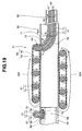
- Fig. 8 shows a capsule endoscope 20, which is configured by providing a thrust generating mechanism section 3A on a capsule 21 whose opposite end portions are hemispherical.
- the capsule endoscope 20 includes an observation optical system, an illumination optical system, various circuits, and the like, which are not shown in the capsule 21 and description of which will be omitted in the present embodiment.
- the circumferentially rotating capsule section 23 is mounted on an open side of the capsule body 22 in such a way as to rotate clockwise and counterclockwise.
- the thrust generating mechanism section 3A includes a flexible shaft 4 and a shaft rotation motor 24 which is a drive motor.
- the flexible shaft 4 is provided as a bendable spirally-shaped portion 4A wound a predetermined number of turns around an outer circumferential face of a trunk portion 21a of the capsule 21, where the trunk portion 21a has a fixed outside diameter size.
- the spirally-shaped portion 4A is a thrust generating section 6A configured by winding the flexible shaft 4 from right to left, where the number of turns is 2.5 turns.
- winding from right to left means winding counterclockwise from the surgeon's hand side toward the distal end when viewed in the travel direction of the capsule body from the surgeon's hand side.
- winding from left to right (described later) means winding clockwise from the surgeon's hand side toward the distal end.
- a shaft distal end member 7 is fixedly mounted on one end of the flexible shaft 4 which makes up the spirally-shaped portion 4A.
- a stepped hole 23a is formed in the circumferentially rotating capsule section 23 in order for the shaft distal end member 7 to be loosely fitted therein.
- the shaft distal end member 7 is placed in a recessed portion 23b.
- An opening of the recessed portion 23b is plugged by fixing a lid member 26 to a stepped portion 23c, for example, by gluing, with the shaft distal end member 7 placed in the recessed portion 23b. This allows that end portion of the flexible shaft 4 to which the shaft distal end member 7 is attached to be turnably mounted on the circumferentially rotating capsule section 23.
- a shaft rotation motor (hereinafter simply referred to as a first motor) 24 and a circumferentially rotating capsule section rotation motor (hereinafter simply referred to as a second motor) 25 are fixed to a predetermined location of the capsule body 22.
- the other end of the flexible shaft 4 introduced into the inner space of the capsule 21 is fixed to a first motor shaft 24a of the first motor 24. Consequently, when the first motor shaft 24a is rotated, for example, in a direction of arrow 9Y1 by driving the first motor 24, the flexible shaft 4 starts to rotate axially in the inner space.
- the flexible shaft 4 makes up the spirally-shaped portion 4A by spiraling around the trunk portion 21a.
- a rotation axis of the flexible shaft 4 is positioned so as to be substantially orthogonal to an insertion direction of the capsule 21. Therefore, the axial rotation of the flexible shaft 4 in the inner space of the capsule 21 is performed around the rotation axis substantially orthogonal to the insertion direction on the outer circumferential face of the trunk portion 21a.
- the flexible shaft 4 is wound in such a way that the shaft axis of the flexible shaft 4 will be substantially orthogonal to the insertion direction on the outer circumferential face of the trunk portion 21a of the capsule 21.
- the state of being substantially orthogonal here allows for an angle of ⁇ between an imaginary line (denoted by reference numeral 8L in Fig. 8 ) orthogonal to a longitudinal axis of the capsule 21 and the inclined central axis of the spiraling flexible shaft 4 (both inclusive).
- the second motor 25 is fixedly mounted on the capsule body 22 such that a second motor shaft 25a of the second motor 25 will coincide with the longitudinal axis of the capsule 21.
- a gear 27 with a predetermined tooth portion 27a on an outer circumferential face is fixedly mounted on the second motor shaft 25a of the second motor 25.
- the tooth portion 27a of the gear 27 meshes with an inner tooth portion 23d formed in a predetermined location of an inner circumferential face of the circumferentially rotating capsule section 23.
- the surgeon Upon determining that the capsule endoscope 20 swallowed by the patient has passed, for example, the stomach, the surgeon turns on the first motor 24 and rotates the first motor shaft 24a in the direction of arrow 9Y1 in Fig. 9 . Consequently, the flexible shaft 4 making up the spirally-shaped portion 4A rotates as follows: the part located on the undersurface of the trunk portion 21a in Fig. 9 rotates counterclockwise around an axis perpendicular to the plane of the paper as described above and the part located on the top surface rotates clockwise around the axis perpendicular to the plane of the paper.
- the surgeon determines that the capsule 21 is advancing without obtaining thrust during the examination, the surgeon gradually rotates the second motor shaft 25a of the second motor 25 in the direction of arrow 9Y2 to bring the spirally-shaped portion 4A into contact with the wall 28a of the lumen 28. Consequently, the spirally-shaped portion 4A gradually increases in outside diameter. Then, if it is determined that the spirally-shaped portion 4A increasing in outside diameter is in contact with the wall 28a of the lumen 28, causing the capsule 21 to move under thrust, the surgeon maintains the outside diameter size of the spirally-shaped portion 4A. Consequently, the capsule 21 moves under the thrust.
- the trunk portion 21a of the capsule 21 is provided with the spirally-shaped portion 4A formed by spirally winding the flexible shaft 4.
- the flexible shaft 4 formed into the spirally-shaped portion 4A increases an area of contact with an inner wall of the lumen, making thrust readily available.
- the second motor 25 is provided in the capsule 21 to turn the circumferentially rotating capsule section 23 with respect to the capsule body 22.
- one end of the flexible shaft 4 which forms the spirally-shaped portion 4A is fixed to the circumferentially rotating capsule section 23 while the other end is fixed to the first motor shaft 24a of the first motor 24 in the capsule body 22 via the body-side hole 22a of the capsule body 22.
- the spirally-shaped portion 4A of the capsule endoscope 20 is wound from right to left.
- the spirally-shaped portion 4A is not limited to winding from right to left, and may be wound from left to right.
- rotating the first motor shaft 24a of the first motor 24 in the direction opposite to the direction of arrow 9Y1 provides thrust used to advance the capsule 21 deep into the lumen 28 in the direction of arrow 9Y.
- the number of turns of the spirally-shaped portion 4A is not limited to 2.5 turns, and may be larger or smaller.
- Figs. 11 and 12 show a body insertion aid 30 equipped with a thrust generating mechanism section 3B.
- the body insertion aid 30 is used in combination with, for example, a catheter for digestive tracts, the trachea, blood vessels, or the urethra or a medical instrument such as an endoscope for the stomach, the small intestine, or the large intestine.
- the body insertion aid 30 includes a longitudinal hollow portion 31 through which a catheter or the insertion portion of an endoscope is passed.
- the thrust generating mechanism section 3B of the body insertion aid 30 includes a flexible shaft 32, multiple ring-shaped belts 33, and an operation/grasping section 5B.
- the flexible shaft 32 mainly makes up a spirally-shaped portion 4B equipped with the longitudinal hollow portion 31.
- the spirally-shaped portion 4B is configured, for example, by winding the flexible shaft 32 from right to left.
- the spirally-shaped portion 4B is an insertion portion inserted near a target site.
- the length of the spirally-shaped portion 4B is set approximately equal to the length of the catheter or the length of the insertion portion of an endoscope.
- a proximal end side of the flexible shaft 32 is extended outward from the longitudinal hollow portion 31 of the spirally-shaped portion 4B as shown in Fig. 12 . This prevents the flexible shaft 32 from crossing a proximal end opening of the longitudinal hollow portion 31, blocking the proximal end opening, and making it difficult to insert the catheter body or the insertion portion of the endoscope through the proximal end opening.
- a proximal end of the flexible shaft 32 is fixed to the operation/grasping section 5B gripped by the surgeon.
- a thrust generating section 6B is configured to be bendable using the spirally-shaped portion 4B and the multiple ring-shaped belts 33.
- Each of the ring-shaped belt 33 is placed by being wound around the spirally-shaped portion 4B.
- the ring-shaped belt 33 is a covering member with which the spirally-shaped portion 4B is covered.
- the ring-shaped belt 33 is a belt strip made of rubber or resin and having predetermined elasticity and predetermined length.
- Each belt strip covers an inner surface of the spirally-shaped portion 4B, for example, starting from the distal end to the proximal end, and then after being turned to the side of an outer surface, covers the outer surface, starting from the proximal end to the distal end. Then, end faces of the belt are joined together by gluing or welding, and consequently the belt strip is wound around the spirally-shaped portion 4B as the ring-shaped belt 33. An outer circumference of the spirally-shaped portion 4B is covered by the multiple ring-shaped belts 33.
- the flexible shaft 32 includes a spirally-shaped tube 34 which is a sheath body and a core wire 35 which is a central body.
- the core wire 35 is passed through the spirally-shaped tube 34 in a loosely fitted state.
- the core wire 35 is made, for example, of an aluminum alloy.
- the core wire 35 is capable of holding the spiral shape of the spirally-shaped portion 4B encircled with the ring-shaped belts 33 and is configured to be elastically deformable under external forces.
- the spirally-shaped tube 34 has flexibility.
- the spirally-shaped tube 34 is integrally made up of a sparsely wound metal coil 36 and a resin coating 37 covering the metal coil 36.
- the metal coil 36 is made, for example, of a nickel-titanium alloy while the resin coating 37 is made of a urethane resin.
- the metal coil 36 is not limited to nickel-titanium alloys, and may be made of another metal or made of resin.
- the resin coating 37 is not limited to urethane resins, and may be made, for example, of a thermoplastic resin, polyester, or the like.
- the proximal end of the spirally-shaped tube 34 which makes up the flexible shaft 32 extended outward from the proximal end opening of the spirally-shaped portion 4B is integrally fixed to the operation/grasping section 5B.
- the core wire 35 of the flexible shaft 32 is configured to be able to be extended outward from an end face of the operation/grasping section 5B through a through-hole 5a formed in the operation/grasping section 5B.
- the body insertion aid 30 has the longitudinal hollow portion 31 which allows passage of a urethral catheter.
- the surgeon inserts the spirally-shaped portion 4B into the urethra 10 by gripping the spirally-shaped portion 4B encircled with the ring-shaped belts 33 with one hand and gripping the operation/grasping section 5B with the other hand.
- the surgeon performs a rotation operation of the operation/grasping section 5B.
- the spirally-shaped tube 34 of the flexible shaft 32 rotates as indicated by arrow 14Y1. That is, that part of the spirally-shaped tube 34 which makes up an upper side of the spirally-shaped portion 4B in Fig. 14 rotates clockwise around an axis perpendicular to the plane of the paper and that part of the spirally-shaped tube 34 which makes up a lower side rotates counterclockwise around the axis perpendicular to the plane of the paper.
- the ring-shaped belts 33 rotate along with rotation of the spirally-shaped tube 34 in the same direction.
- a frictional force is generated between the ring-shaped belts 33 and the wall 10a.
- the frictional force provides the thrust used to move the body insertion aid 30 in a direction of arrow 14Y. This allows the surgeon to push the body insertion aid 30 forward smoothly into deep part using, as auxiliary power, the thrust provided by the ring-shaped belts 33.
- the surgeon After confirming that a distal end portion of the body insertion aid 30 has reached near the bladder, the surgeon leads a distal end of the urethral catheter to the bladder through the longitudinal hollow portion 31 of the body insertion aid 30.
- the thrust generating section 6B is configured by winding the multiple ring-shaped belts 33 around the spirally-shaped portion 4B with the multiple ring-shaped belts 33 kept in contact with the spirally-shaped portion 4B. Consequently, by turning the spirally-shaped tube 34 of the flexible shaft 32 of the spirally-shaped portion 4B, the ring-shaped belts 33 wound around the spirally-shaped portion 4B can be rotated clockwise or counterclockwise. Besides, as the ring-shaped belts 33 wound around the spirally-shaped portion 4B are placed in contact with the wall 10a, rotation of the ring-shaped belts 33 provides the thrust used to advance or retract the body insertion aid 30.
- the thrust generating section 6B made up of the spirally-shaped portion 4B and the multiple ring-shaped belts 33 placed by being wound around the spirally-shaped portion 4B is configured to be bendable. This allows the body insertion aid 30 to be inserted into a curved duct.
- the ring-shaped belts 33 wound around the spirally-shaped portion 4B are placed in contact with the wall. This increases a contact area between the thrust generating section 6B and the wall compared to when the flexible shaft 4 is placed in contact with the wall such as in the embodiment described above, and thereby makes thrust readily available.
- the spirally-shaped portion 4B may be used singly as the thrust generating section without being covered by the multiple ring-shaped belts 33. This eliminates the need for the power used to rotate the ring-shaped belts 33.
- reference numeral 40 denotes an endoscope system.
- the endoscope system 40 includes an endoscope 42, a light source device 43, a video processor 44, a monitor 45, and a rotational driving device 46, where the endoscope 42 includes a thrust generating mechanism section 3C in an insertion portion 41 and the rotational driving device 46 is a driving section for the thrust generating mechanism section 3C.
- Reference numeral 47 denotes a trolley on which the light source device 43, the video processor 44, the monitor 45, and the rotational driving device 46 are mounted.
- the insertion portion 41 has flexibility and elongated shape in order to be inserted into a lumen.
- An operation section 48 is provided in a proximal end portion of the insertion portion 41.
- a universal code 49 and a rotational driving force transmission tube 50 extend outward from lateral part of the operation section 48.
- a proximal end portion of the universal code 49 is connected to the light source device 43.
- a proximal end portion of the rotational driving force transmission tube 50 is connected to the rotational driving device 46.
- the light source device 43 supplies the endoscope 42, for example, with illumination light for normal light observation mode, i.e., white light radiated for observation of a site to be treated, and illumination light for narrow-band observation mode, i.e., narrow-band light emitted for detection of cancer and the like.
- the illumination light is emitted from an illumination window (reference numeral 51a in Fig. 16 ) of the illumination optical system.
- the video processor 44 is provided with a drive circuit (not shown), a signal processing circuit (not shown), and the like.
- the drive circuit drives an image pickup device (not shown) of the endoscope 42.
- the signal processing circuit receives an electrical signal resulting from photoelectric conversion of an image formed on an image pickup surface of the image pickup device through an observation window (reference numeral 51b in Fig. 16 ) of the observation optical system and converts the electrical signal into a video signal.
- the video signal generated by the signal processing circuit is outputted to a monitor 45, and consequently the image captured by the image pickup device is displayed on a display screen 45a of the monitor 45.
- the insertion portion 41 includes a distal end portion 51, a bending portion 52, and a flexible tubular portion 53 which are linked in the order starting from the distal end side.
- the bending portion 52 is configured to bend in up-and-down and left-to-right directions, for example, by linking multiple bending pieces together.
- the flexible tubular portion 53 is provided with the thrust generating mechanism section 3C.
- the operation section 48 is provided, for example, with a bending operation knob 54, an air/water supply button 55, a suction button 56, a rotational driving device operation switch (hereinafter simply referred to as an operation switch) 57, and the like.
- the operation switch 57 turns on the rotational driving device 46.
- the bending operation knob 54 causes the bending portion 52 to perform bending actions. When operated by the surgeon, the bending operation knob 54 causes the bending portion 52 to bend by drawing and relaxing a bending wire extending outward from the bending portion 52.
- the air/water supply button 55 is used to control air/water supply.
- the air/water supply button 55 is an operation button used to spray air or water toward the observation window 51b and the like from a nozzle (reference numeral 51c in Fig. 16 ). Either air or water is supplied depending on the operation performed by the surgeon.
- the suction button 56 is used to control suction.
- the suction button 56 is operated by the surgeon to suck body fluids, the water sprayed to the observation window, and the like through a distal end opening (reference numeral 51d in Fig. 16 ) provided in the distal end portion 51.
- the thrust generating mechanism section 3C will be described with reference to Figs. 16 to 20 .
- the thrust generating mechanism section 3C includes a flexible shaft 61 and a spirally-shaped portion covering (hereinafter simply referred to as a covering) 62 shown in Fig. 16 as well as a pair of rotation motors 63 provided in the rotational driving device 46 and shown in Fig. 18 .
- a driving force transmission gear 64 is fixed to a proximal end portion of the flexible shaft 61.
- the driving force transmission gear 64 meshes with gears 65 fixedly mounted, respectively, on motor shafts 63a of the pair of rotation motors 63.
- the driving force transmission gear 64 is sandwiched between the pair of gears 65.
- the flexible shaft 61 is configured to rotate in a direction of arrow 18Y or in the opposite direction by being driven by the pair of rotation motors 63.
- the flexible shaft 61 is formed into a spirally-shaped portion 4C wound from left to right.
- the spirally-shaped portion 4C is provided adjacent to the bending portion 52 on a distal end side of the flexible tubular portion 53.
- a thrust generating section 6C is configured to be bendable using the spirally-shaped portion 4C and a covering 62 provided on the spirally-shaped portion 4C.
- the covering 62 is a covering member adapted to cover the spirally-shaped portion 4C.
- the covering 62 is configured to be an elastically deformable sheet made of fluoro rubber, urethane rubber, or the like and having predetermined elasticity and predetermined shape.
- the bendable thrust generating section 6C made up of the spirally-shaped portion 4C and the covering 62 is provided on the flexible tubular portion 53, it becomes possible to prevent loss of flexibility in the flexible tubular portion 53.
- An outer circumferential face on the distal end side of the flexible tubular portion 53 is provided with a front opening 58 and a rear opening 59 through which the flexible shaft 61 is passed.
- a straight line joining a center of the front opening 58 and a center of the rear opening 59 is disposed so as to be parallel to a longitudinal axis of the insertion portion 41 stretched into a linear shape.
- the covering 62 is substantially C-shaped when viewed from the front and is placed in the insertion portion 41.
- a distal face of the distal end portion 51 of the insertion portion 41 is equipped, for example, with two illumination windows 51a, the observation window 51b, the nozzle 51c, and the distal end opening 51d.
- the flexible shaft 61 includes a shaft body 71, which is a sheath, and a core wire 72.
- the shaft body 71 is configured as two close-wound layers of flexible nonstranded metal wires 71a made, for example, of stainless steel as shown in Fig. 20 to improve rotation transmission.
- the shaft body 71 has an inner layer 71i wound from right to left and an outer layer 71o wound from left to right.
- the nonstranded metal wires of the shaft body 71 are not limited to stainless steel, and may be made of another metal such as tungsten wires, or a resin. Also, although the shaft body 71 has two layers in the present embodiment, the shaft body 71 may have three or four layers.
- the core wire 72 is passed through the shaft body 71 in a loosely fitted state.
- the core wire 72 is made, for example, of stainless steel.
- the core wire 72 is capable of holding the spiral shape of the spirally-shaped portion 4C with the covering 62 disposed around the spirally-shaped portion 4C and is configured to be elastically deformable under external forces.
- the flexible shaft 61 which forms the spirally-shaped portion 4C is disposed on a stepped hole 67 configured to communicate with the front opening 58.
- the stepped hole 67 is formed in a coupling member 66.
- the coupling member 66 is a coupling tube configured to couple the flexible tubular portion 53 and the bending portion 52 which make up the insertion portion 41 of the endoscope 42.
- the stepped hole 67 is made up of a retention hole 68, a shaft distal end placement hole 69, and a core wire placement hole 70 starting from the distal end side.
- a shaft distal end member 73 is integrally fixed to a distal end face of the shaft body 71 of the flexible shaft 61 by joining such as soldering.
- the shaft distal end member 73 has a flat ring shape with a central through-hole 74, and outside diameter size of the shaft distal end member 73 is configured to be larger than diameter size of the shaft body 71.
- the core wire 72 of the flexible shaft 61 is passed through the central through-hole 74 of the shaft distal end member 73.
- a distal end portion of the core wire 72 is placed in the core wire placement hole 70 and integrally fixed, for example, by gluing.
- the shaft distal end member 73 which is a distal end of the flexible shaft 61 is placed in the shaft distal end placement hole 69. Being placed in this way, the shaft distal end member 73 is turnably mounted in the shaft distal end placement hole 69 by fixedly bonding a lid member 75 to the retention hole 68.
- a proximal end side of the flexible shaft 61 which makes up the spirally-shaped portion 4C is introduced into the flexible tubular portion 53 through an intra-insertion portion communication hole 76 provided so as to communicate with the rear opening 59.
- the flexible shaft 61 introduced into the flexible tubular portion 53 is designed to be fixedly mounted to a coupling/fixing section 60 provided in the rotational driving device 46 by passing through the rotational driving force transmission tube 50 extending outward from the operation section 48 provided in the proximal end portion of the insertion portion 41.
- the intra-insertion portion communication hole 76 is formed in a shaft introduction member 77 fixedly mounted near the rear opening 59.
- One opening of the intra-insertion portion communication hole 76 formed in the shaft introduction member 77 is placed in such a way as to communicate with the rear opening 59.
- a distal end portion of a shaft guide tube 78 is fixedly mounted to the other opening of the intra-insertion portion communication hole 76.
- a proximal end portion of the shaft guide tube 78 is fixedly mounted to the proximal end portion of the insertion portion 41.
- a proximal end of the flexible shaft 61 which forms the spirally-shaped portion 4C is designed to be led to the side of the operation section 48 by passing through the shaft guide tube 78 after passing the rear opening 59 and the intra-insertion portion communication hole 76.
- an air/water supply tube, a suction tube, an image pickup cable, a bending wire, and the like are passed through the insertion portion 41.
- the covering 62 covers an inner surface of the spirally-shaped portion 4C, for example, from the proximal end to the distal end of the spirally-shaped portion 4C, and then after being turned to the side of an outer surface, covers the outer surface from the proximal end to the distal end. Then, end faces of belts are joined together by gluing or welding, and the belts are provided around the spirally-shaped portion 4C as the covering 62.
- the covering 62 covers substantially an entire circumference of the spirally-shaped portion 4C excluding an area 79 indicated by broken lines on opposite sides of 19Y-19Y line in Fig. 16 . This provides a larger area of contact with luminal walls than when the belts 33 are arranged in the circumferential direction as described above.
- the endoscope system 40 is equipped with the spirally-shaped portion 4C covered with the covering 62.
- the outside diameter of the flexible tubular portion 53 including the covering 62 is set to such a size as to allow the flexible tubular portion 53 to pass the anus smoothly. That is, the insertion portion 41 is inserted into the large intestine.
- the surgeon When inserting the insertion portion 41 into the large intestine, the surgeon inserts the distal end portion 51 of the insertion portion 41 gradually into the large intestine by gripping the insertion portion 41 with one hand and gripping the operation section 48 with the other hand.
- the surgeon bends the bending portion 52 by operating the bending operation knob 54 and thereby hooks the distal end portion 51 onto the splenic flexure 81.
- the surgeon pushes in the insertion portion 41 from outside the body.
- the bent bending portion 52 acting as resistance, the force exerted by the surgeon to push in the insertion portion 41 is difficult transmit to the distal end portion 51.
- the rotation of the shaft body 71 is transmitted gradually to the distal end side through different parts of the shaft body 71, i.e., through the part passed through the insertion portion 41 and the part wound around the flexible tubular portion 53 configuring the spirally-shaped portion 4C. Then, the shaft distal end member 73 placed in the shaft distal end placement hole 69 of the stepped hole 67 enters a rotating state, putting the entire shaft body 71 into a rotating state. Subsequently, as the rotation of the rotation motors 63 is continued, the shaft body 71 continues rotating.
- the shaft body 71 makes up the spirally-shaped portion 4C by being placed in such a way as to spiral around the flexible tubular portion 53. Consequently, a rotation axis of the shaft body 71 is positioned so as to be substantially orthogonal to an insertion direction of the insertion portion 41. That is, the shaft body 71 is wound in such a way that a shaft axis of the shaft body 71 will be substantially orthogonal to the insertion direction on an outer circumferential face of the flexible tubular portion 53.
- the shaft axis is a longitudinal central axis of the shaft body 71.
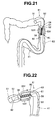
- the covering 62 which is placed in contact with the shaft body 71, rotates as indicated by arrow 53Y in Figs. 19 and 21 .
- a frictional force is generated between large intestine walls 82 and the covering 62.
- the distal end side of the flexible tubular portion 53 passes the splenic flexure 81 as shown in Fig. 22 .
- the thrust generating section 6C is configured by forming the spirally-shaped portion 4C on the distal end side of the flexible tubular portion 53 which makes up the insertion portion 41 of the endoscope 42 and placing the covering 62 in contact with the spirally-shaped portion 4C. Consequently, by turning the shaft body 71 of the flexible shaft 61 which makes up the spirally-shaped portion 4C, the covering 62 which covers the spirally-shaped portion 4C can be rotated clockwise or counterclockwise.
- the rotation of the covering 62 provides the thrust used to advance or retract the insertion portion 41.
- the use of the covering 62 to cover the spirally-shaped portion 4C provides a larger area of contact with the walls than when the ring-shaped belts 33 are used, and thereby makes thrust readily available.
- the thrust generating mechanism section 3C is made up of the rotational driving device 46 which is an outside apparatus as well as components provided in the flexible tubular portion 53, including the spirally-shaped portion 4C formed by the flexible shaft 61 and the covering 62 which covers the spirally-shaped portion 4C. This makes it possible to include parts and the like used to switch the rotational direction of the covering 62 in the outside apparatus and thereby prevent increases in the diameter of the insertion portion 41.
- the thrust generating section 6C is provided on the distal end side of the flexible tubular portion 53 which makes up the insertion portion 41.
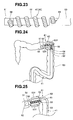
- the thrust generating section 6C is configured to be bendable using the spirally-shaped portion 4C and the covering 62 provided on the spirally-shaped portion 4C, the thrust generating section 6C made up of the spirally-shaped portion 4C and a covering (not shown) may be provided in the bending portion 52 as shown in Fig. 23 .
- the front opening 58 which allows passage of the flexible shaft 61 is provided in the distal end portion 51 and the rear opening 59 is provided in the bending portion 52 or the flexible tubular portion 53. Then, a stepped hole (not shown) is formed in a distal rigid member (not shown) in such a way as to communicate with the front opening 58, where the distal rigid member makes up the distal end portion 51 which is coupled to the bending pieces which make up the bending portion 52.
- the intra-insertion portion communication hole is provided in a coupling member (not shown) which couples the flexible tubular portion 53 and the bending portion 52, so as to communicate between the coupling member and the rear opening 59.
- the thrust generating section 6C is provided in the bending portion 52 in this way, when the distal end portion 51 of the insertion portion 41 reaches the splenic flexure 81, by operating the bending operation knob 54, the surgeon can bend the bending portion 52 equipped with the thrust generating section 6C as shown in Fig. 24 and thereby hook the distal end portion 51 onto the splenic flexure 81.
- the thrust generating section 6C can be placed further on the distal end side of the insertion portion 41, making it possible to obtain thrust used to advance the insertion portion 41 more efficiently.
- the thrust generating mechanism section in Fig. 26 is configured similarly to the fourth embodiment in terms of the thrust generating section 6C, but differs in an internal configuration of the rotational driving device 46.
- the rotational driving device 46 includes a rotational driving unit 90 and a driving unit advance/retract device 91.
- the rotational driving unit 90 is configured by integrally fixing the pair of rotation motors 63 and the like to a boxlike body 92.
- the boxlike body 92 can freely advance and retract in an extending direction of the flexible shaft in the rotational driving device 46.
- the driving unit advance/retract device 91 is equipped, for example, with a rack and pinion mechanism adapted to advance and retract the boxlike body 92.
- An advance/retract motor (not shown) of the rack and pinion mechanism is integrally fixed to the rotational driving device 46.
- a tooth portion provided on a motor shaft is rotated by the advance/retract motor provided in the driving unit advance/retract device 91. Consequently, along with the rotation of the tooth portion, the rack meshed with the tooth portion advances, causing the boxlike body 92 of the rotational driving unit 90 to move toward the distal end side by a distance L in the rotational driving device 46.
- the flexible shaft 61 passed through the rotational driving force transmission tube 50 and the flexible tubular portion 53 is moved as well. That is, the flexible shaft 61 is pushed out of the rear opening 59.
- the spiral of a spirally-shaped portion 4D of a thrust generating mechanism section 3D provided around the flexible tubular portion 53 has five turns and the outside diameter size of each turn is ⁇ D, circumferential length of each turn is ⁇ D and a sum of the circumferential lengths of the spirally-shaped portion 4D is 5 ⁇ D.
- the advanceable/retractable rotational driving unit 90 is provided in the rotational driving device 46, the driving unit advance/retract device 91 is provided to advance and retract the rotational driving unit 90, and the placement location of the rotational driving unit 90 is changed by operating the driving unit advance/retract device 91 as required.
- This makes it possible to change the outside diameter size of the spirally-shaped portion 4D as required according to the inside diameter of the lumen by pushing the flexible shaft 61 out of the rear opening 59 and thereby obtain thrust efficiently.
- the intraductal insertion device is a medical instrument in the embodiments described above, the intraductal insertion device is not limited to medical instruments, and may be an instrument used to inspect piping in a factory, i.e., an instrument other than medical instruments.
Landscapes
- Health & Medical Sciences (AREA)
- Life Sciences & Earth Sciences (AREA)
- Surgery (AREA)
- Engineering & Computer Science (AREA)
- Heart & Thoracic Surgery (AREA)
- Biophysics (AREA)
- Veterinary Medicine (AREA)
- Public Health (AREA)
- General Health & Medical Sciences (AREA)
- Animal Behavior & Ethology (AREA)
- Biomedical Technology (AREA)
- Medical Informatics (AREA)
- Physics & Mathematics (AREA)
- Molecular Biology (AREA)
- Radiology & Medical Imaging (AREA)
- Pathology (AREA)
- Optics & Photonics (AREA)
- Nuclear Medicine, Radiotherapy & Molecular Imaging (AREA)
- Robotics (AREA)
- Pulmonology (AREA)
- Anesthesiology (AREA)
- Hematology (AREA)
- Gastroenterology & Hepatology (AREA)
- Endoscopes (AREA)
Abstract
Description
- The present invention relates to an intraductal insertion device which can advance and retract an insertion portion in a duct using thrust developed by a thrust generating section.
- Conventionally, an intraductal insertion device such as a catheter is inserted directly into the urethra or the like. Also, an elongated insertion portion of an endoscope is inserted, for example, into the stomach through the oral cavity, or into the large intestine or the like through the anus.
- Generally, the endoscope is equipped with a bending portion on a distal end side of the elongated insertion portion, where the bending portion is configured by linking bending pieces together, for example, to perform bending operation in up-and-down and left-to-right directions. The bending portion is configured to perform bending operation when a surgeon operates, for example, a bending knob provided in an operation section and thereby advances and retracts an operation wire connected to the bending pieces.
- It requires skill to learn to pass the insertion portion of the endoscope smoothly through an intricate duct in a short time. In particular, surgeons inexperienced in handling endoscopes used to take a lot of time inserting the insertion portion into deep part of the large intestine. Thus, in order to improve insertability of the insertion portion, various proposals have been made to pass the insertion portion through to a target site by means of thrust.
- For example,
US patent No. 7,048,717 discloses an endoscope insertion aid device and the like equipped with a spiral structure. With the endoscope insertion aid device, when a spiral structural portion provided in an insertion portion of an endoscope is rotated around the axis of the insertion portion by rotating a handle, the spiral structural portion and large intestine walls form a relationship such as between an external thread and an internal thread, providing thrust for the insertion portion to move forward in the intestine. - However, in a case where the relationship between the external thread and the internal thread is not sufficiently established in the contact of the spiral structural portion and the large intestine walls, the spiral structural portion provided at the insertion portion is raced around its axis to render it difficult to obtain the thrust.
- On the other hand, Japanese Patent Application Laid-Open Publication No.
2006-523613 - However, in the self-propelled endoscope apparatus of
Patent Document 2, a drive mechanism equipped with rollers, etc. for circulating the toroid by continuous motion has complicated configuration. Thus, the provision of the drive mechanism having the complicated configuration on the distal end side of the insertion portion may cause a problem of an increase of a diameter of the insertion portion or a decrease of flexibility of the insertion portion. - The present invention has been made in view of the above circumstances, and an object of the present invention is to provide an intraductal insertion device comprising a thrust generating mechanism section for obtaining thrust by contact with the interior of the duct, and preventing the increase of the diameter and the decrease of flexibility of the insertion portion which is equipped with the thrust generating mechanism section.
- An intraductal insertion device according to the present invention comprises a thrust generating section installed at an insertion portion, wherein the thrust generating section includes a flexible shaft adapted to rotate clockwise or counterclockwise around a shaft axis; and the shaft axis of the flexible shaft is wound around an axis of the insertion portion in an insertion direction.
-
-
Figs. 1 to 5 concern a first embodiment of the present invention, where:-
Fig. 1 is a diagram illustrating an intraductal insertion device equipped with a thrust generating section arranged and configured by winding a flexible shaft around an outer circumferential face of a catheter body at least half a turn or more; -
Fig. 2 is a sectional view illustrating a configuration on a distal end side of the flexible shaft wound around the outer circumferential face of the catheter body as well as how the flexible shaft is led out of an insertion portion; -
Fig. 3 is a diagram when a shaft holding member is viewed from the side of a curved surface; -
Fig. 4 is a diagram when the shaft holding member is viewed from a plane facing the curved surface; and -
Fig. 5 is a diagram illustrating operation of a catheter arranged by winding the flexible shaft around the outer circumferential face of the catheter body half a turn or more in a circumferential direction;
-
-
Figs. 6 and 7 concern a variation of the first embodiment, where:-
Fig. 6 is a sectional view illustrating a catheter body provided with a circumferential shaft groove; and -
Fig. 7 is a diagram illustrating operation of a catheter with the flexible shaft placed in the circumferential shaft groove of the catheter body.
-
-
Figs. 8 to 10B are diagrams concerning a second embodiment of the present invention and illustrating a capsule endoscope equipped with a thrust generating section; where -
Fig. 9 is a longitudinal sectional view of the capsule endoscope equipped with the thrust generating section and is a diagram illustrating operation of the capsule endoscope;-
Fig. 10A is a diagram illustrating a relationship between a circumferentially rotating capsule section rotation motor and a circumferentially rotating capsule section; and -
Fig. 10B is a diagram illustrating a spirally-shaped portion when the circumferentially rotating capsule section is rotated one turn by the circumferentially rotating capsule section rotation motor;
-
-
Figs. 11 to 14 concern a third embodiment of the present invention, where:-
Fig. 11 is a diagram illustrating a body insertion aid equipped with a thrust generating section; -
Fig. 12 is a diagram when the body insertion aid is viewed in a direction ofarrow 12Y inFig. 11 ; -
Fig. 13 is a sectional view illustrating a configuration of the flexible shaft; and -
Fig. 14 is a sectional view taken alongline 14Y-14Y inFig. 12 to illustrate operation of the body insertion aid;
-
-
Figs. 15 to 22 concern a fourth variation of the present invention, where:-
Fig. 15 is a diagram illustrating an endoscope system equipped with an endoscope whose insertion portion is provided with a thrust generating section; -
Fig. 16 is a diagram of the thrust generating section whose flexible shaft is covered with a spirally-shaped portion covering, as viewed in a direction ofarrow 16Y inFig. 15 ; -
Fig. 17 is a diagram of the insertion portion covered with the spirally-shaped portion covering, as viewed in a direction ofarrow 17Y inFig. 16 ; -
Fig. 18 is a diagram illustrating a configuration of the flexible shaft and an internal configuration of a rotational driving device; -
Fig. 19 is a sectional view taken alongline 19Y-19Y indicated by arrows inFig. 16 to illustrate operation of the spirally-shaped portion and spirally-shaped portion covering, the spirally-shaped portion being made up of the flexible shaft provided in a flexible tube portion and the spirally-shaped portion covering being placed around the spirally-shaped portion; -
Fig. 20 is a diagram illustrating a configuration of a shaft body; -
Fig. 21 is a diagram illustrating operation of the insertion portion whose flexible portion is equipped with the thrust generating section made up of the flexible shaft covered with the spirally-shaped portion covering; and -
Fig. 22 is a diagram illustrating how the insertion portion has passed the splenic flexure by means of thrust developed by the thrust generating section provided in the flexible portion;
-
-
Fig. 23 is a diagram illustrating an exemplary configuration of the insertion portion whose bending portion is provided with the thrust developed by the thrust generating section; -
Fig. 24 is a diagram illustrating operation of the insertion portion whose bending portion is equipped with the thrust generating section made up of the flexible shaft covered with the spirally-shaped portion covering; -
Fig. 25 is a diagram illustrating how the insertion portion has passed the splenic flexure by means of thrust developed by the thrust generating section provided in the bending portion; and -
Fig. 26 is a diagram illustrating a configuration and operation of a rotational driving unit and a driving unit advance/retract device provided in the rotational driving device. - Embodiments of the present invention will be described below with reference to the drawings.
- A first embodiment of the present invention will be described with reference to
Figs. 1 to 5 . - A
catheter 1 shown inFig. 1 is an intraductal insertion device used, for example, to drain urine. Thecatheter 1 includes acatheter body 2 which is flexible and a thrustgenerating mechanism section 3. Thecatheter body 2 is an insertion portion inserted into a target site such as the urethra. - The thrust
generating mechanism section 3 includes aflexible shaft 4 and an operation/grasping section 5. Theflexible shaft 4, shaped in the form of a close-wound coil spring, is a rotating shaft which has flexibility and excels in rotation transmission. The operation/graspingsection 5 is used to rotate theflexible shaft 4 clockwise or counterclockwise around a shaft axis. The operation/graspingsection 5 is a cylindrical member made, for example, of resin and intended to be gripped by a surgeon. Incidentally, the shaft axis is a longitudinal central axis of theflexible shaft 4. - As shown in
Figs. 1 and 2 , thecatheter body 2 is an elongated tubular body and a through-hole 2a is formed through thecatheter body 2, centering around a longitudinal axis. Also, afirst hole 2b and asecond hole 2c are formed in an outer circumferential face of thecatheter body 2 to communicate between the through-hole 2a and the outside. - According to the present embodiment, the
first hole 2b and thesecond hole 2c are formed such that respective centers will be located on the same circumference. Thefirst hole 2b and thesecond hole 2c are provided so as to be spaced in a circumferential direction, for example, such that theflexible shaft 4 led out of thefirst hole 2b and led to the inside through thesecond hole 2c will be placed by being wound around the outer circumferential face of thecatheter body 2 at least half a turn or more. - The
flexible shaft 4 according to the present embodiment is mainly passed through the through-hole 2a of thecatheter body 2. On a distal end side, theflexible shaft 4 is exposed from a distal end side portion of the outer circumferential face of thecatheter body 2 and placed by being wound in the circumferential direction. A proximal end portion of theflexible shaft 4 is integrally fixed to the operation/graspingsection 5. The distal end side of theflexible shaft 4 exposed from the distal end side portion of the outer circumferential face of thecatheter body 2 is configured as athrust generating section 6. - The distal end side of the
flexible shaft 4 is led out of the through-hole 2a, for example, via thefirst hole 2b, subsequently placed on the side of the outer circumferential face where thefirst hole 2b and thesecond hole 2c are located at some distance from each other, and led into the through-hole 2a again through thesecond hole 2c. The distal end side of theflexible shaft 4 is designed to be placed in a predetermined portion of a shaft holding member 8 (described later) in such a way as to be turnable with respect to thesecond hole 2b. - Referring to
Fig. 2 ,reference numeral 7 denotes a shaft distal end member. The shaftdistal end member 7 is integrally fixed to a distal end of theflexible shaft 4 by joining such as soldering. The shaftdistal end member 7 has, for example, a flat cylindrical shape, and outside diameter size of the shaftdistal end member 7 is larger than diameter size of theflexible shaft 4. That is, the shaftdistal end member 7 is a fall prevention member which prevents the distal end of theflexible shaft 4 from coming off ashaft passage hole 8c (described later). - As shown in
Figs. 2 to 4 , theshaft holding member 8 includes ashaft placement groove 8a and a shaft distalend holding hole 8b. Theshaft placement groove 8a is formed into a curved shape so as to guide theflexible shaft 4 passing through the through-hole 2a to thefirst hole 2b. - The shaft distal
end holding hole 8b is a stepped through-hole which has theshaft passage hole 8c and a shaft distalend placement hole 8d. Theflexible shaft 4 is passed through theshaft passage hole 8c in a loosely fitted state. The shaftdistal end member 7 is placed in the shaft distalend placement hole 8d in a loosely fitted state. That is, theshaft passage hole 8c is formed to be smaller in diameter size than the shaft distalend placement hole 8d. - Thus, the shaft
distal end member 7 which makes up a distal end portion of theflexible shaft 4 is turnable in the shaft distalend placement hole 8d. - The
shaft holding member 8 is made of flexible rubber or resin. Theshaft holding member 8 is fixed integrally to a predetermined position of the through-hole 2a in thecatheter body 2 by gluing or welding. Specifically, theshaft holding member 8 is integrally fixed to thecatheter body 2, with acurved surface 8e of theshaft holding member 8 placed in close contact with an inner surface of the through-hole 2a, with thesecond hole 2c and the shaft distalend holding hole 8b communicated with each other, and with thefirst hole 2b facing theshaft placement groove 8a in a desired condition. - Incidentally, a
plug member 9 may be disposed on an open side of the shaft distalend placement hole 8d. Theplug member 9, when provided on the open side of the shaft distalend placement hole 8d, prevents the distal end portion of theflexible shaft 4, with the shaftdistal end member 7 fixedly mounted thereon, form falling off the shaft distalend placement hole 8d to inside the through-hole 2a. - Operation of the
catheter 1 configured as described above will be described. - When inserting the
catheter body 2 of thecatheter 1 into theurethra 10, the surgeon inserts thecatheter body 2 gradually into theurethra 10 by gripping thecatheter body 2 with one hand and gripping the operation/graspingsection 5 with the other hand. Then, with theflexible shaft 4 of thecatheter body 2 placed in contact with awall 10a of theurethra 10, the surgeon performs a rotation operation on the operation/graspingsection 5. - Consequently, as shown in
Fig. 5 , theflexible shaft 4 rotates in the through-hole 2a as indicated by arrow 5Y1. Then, a rotational force resulting from the rotation operation of the operation/graspingsection 5 is gradually transmitted to the distal end side. Consequently, theflexible shaft 4 placed on a distal end side of the outer circumferential face of thecatheter body 2 rotates as indicated by arrows 5Y2 and 5Y3. Subsequently, the shaftdistal end member 7 placed in the shaft distalend placement hole 8d also enters a rotating state, resulting in rotation of the entireflexible shaft 4. Then, as the surgeon continues the rotation operation of the operation/graspingsection 5, theflexible shaft 4 continues to rotate. - In so doing, that part of the
flexible shaft 4 which is located on an undersurface of thecatheter body 2 in theFig. 5 rotates counterclockwise around an axis perpendicular to the plane of the paper and that part of theflexible shaft 4 which is located on a top surface rotates clockwise around the axis perpendicular to the plane of the paper. That is, since theflexible shaft 4 is placed in the circumferential direction on the distal end side of the outer circumferential face of thecatheter body 2, the axial rotation of theflexible shaft 4 passing through the through-hole 2a, on the outer circumferential face, is rotation around an axis orthogonal to an insertion direction. In other words, theflexible shaft 4 is wound such that the shaft axis of theflexible shaft 4 will be orthogonal to the insertion direction on the outer circumferential face of thecatheter body 2. - Consequently, since the
flexible shaft 4 being rotated remains in contact with thewall 10a, a frictional force is generated between thewall 10a and theflexible shaft 4 and acts as thrust which moves thecatheter body 2 in a direction ofarrow 5Y. This allows the surgeon to push thecatheter body 2 forward smoothly into deep part using, as auxiliary power, the thrust developed by the rotatingflexible shaft 4 placed in contact with thewall 10a. - In this way, the
flexible shaft 4 is axially rotated through rotation operation of the operation/graspingsection 5. In the rotating state, since theflexible shaft 4 wound in the circumferential direction around the outer circumferential face of thecatheter body 2 on the distal end side is placed in contact with the wall, theflexible shaft 4 provides thrust used to advance or retract thecatheter body 2. - This makes it possible to insert the
catheter body 2 smoothly into theurethra 10. - Also, by simply placing part of the
flexible shaft 4 on the outer circumferential face of thecatheter body 2, it is possible to reduce the diameter of the catheter equipped with thethrust generating section 6. - Incidentally, if the operation/grasping
section 5 is rotated in such a way as to rotate theflexible shaft 4 in the through-hole 2a in a direction opposite to arrow 5Y1, theflexible shaft 4 placed in contact with thewall 10a provides thrust which tends to move thecatheter body 2 in a direction opposite to the direction ofarrow 5Y, i.e., retract thecatheter body 2. - A variation of the catheter will be described with reference to
Figs. 6 and 7 . - As shown in
Figs. 6 and 7 , acatheter body 2S has acircumferential shaft groove 2d of a predetermined depth formed in an outer circumferential face of thecatheter body 2 extending from thefirst hole 2b to thesecond hole 2c. Theflexible shaft 4 is placed in thecircumferential shaft groove 2d. - Consequently, maximum outside diameter φS of the insertion portion of the
catheter body 2 with theflexible shaft 4 placed in thecircumferential shaft groove 2d as shown inFig. 6 can be made smaller than maximum outside diameter φL (indicated by a chain double-dashed line) of the insertion portion of theflexible shaft 4 placed along the outer circumferential face 2o of thecatheter body 2 as in the case of the embodiment described above. - Also, the
flexible shaft 4, when placed in thecircumferential shaft groove 2d, can prevent a placement location of theflexible shaft 4 from being changed by resistance from thewall 10a when thecatheter body 2 is inserted into theurethra 10. Consequently, theflexible shaft 4 comes into contact with thewall 10a in a stable manner, readily providing thrust used to advance thecatheter body 2. - Desirably, the depth of the
circumferential shaft groove 2d is not larger than half the diameter of theflexible shaft 4, and approximately half the circumference of theflexible shaft 4 is placed in thecircumferential shaft groove 2d. - Also, in the embodiment described above, the thrust generating section is configured by forming the
first hole 2b and thesecond hole 2c on the same circumference and placing theflexible shaft 4 in the circumferential direction on the distal end side of the outer circumferential face of thecatheter body 2. However, with thefirst hole 2b and thesecond hole 2c formed so as to be spaced in a longitudinal direction of thecatheter body 2, theflexible shaft 4 led out through thefirst hole 2b may be wound around the outer circumferential face of thecatheter body 2, forming a spiral shape, which can be used as a thrust generating section. - Furthermore, in the embodiment described above, the surgeon performs a rotation operation manually by gripping the operation/grasping
section 5. However, a driving device adapted to rotate the operation/graspingsection 5 may be provided to axially rotate theflexible shaft 4. - Besides, in the embodiment described above, the intraductal insertion device is a catheter used to drain urine. However, the catheter is not limited to a urethral catheter, and the
thrust generating section 6 may be provided on catheters for other lumens such as digestive tracts, the trachea, and blood vessels. - A second embodiment of the present invention will be described with reference to
Figs. 8 to 10B . -
Fig. 8 shows acapsule endoscope 20, which is configured by providing a thrustgenerating mechanism section 3A on acapsule 21 whose opposite end portions are hemispherical. Thecapsule endoscope 20 includes an observation optical system, an illumination optical system, various circuits, and the like, which are not shown in thecapsule 21 and description of which will be omitted in the present embodiment. - The
capsule 21, which is an insertion portion swallowed and inserted into a lumen, includes acapsule body 22 and a circumferentiallyrotating capsule section 23. The circumferentiallyrotating capsule section 23 is mounted on an open side of thecapsule body 22 in such a way as to rotate clockwise and counterclockwise. - The thrust
generating mechanism section 3A includes aflexible shaft 4 and ashaft rotation motor 24 which is a drive motor. Theflexible shaft 4 is provided as a bendable spirally-shapedportion 4A wound a predetermined number of turns around an outer circumferential face of atrunk portion 21a of thecapsule 21, where thetrunk portion 21a has a fixed outside diameter size. According to the present embodiment, the spirally-shapedportion 4A is athrust generating section 6A configured by winding theflexible shaft 4 from right to left, where the number of turns is 2.5 turns. Incidentally, winding from right to left means winding counterclockwise from the surgeon's hand side toward the distal end when viewed in the travel direction of the capsule body from the surgeon's hand side. On the other hand, winding from left to right (described later) means winding clockwise from the surgeon's hand side toward the distal end. - As shown in
Fig. 9 , a shaftdistal end member 7 is fixedly mounted on one end of theflexible shaft 4 which makes up the spirally-shapedportion 4A. A steppedhole 23a is formed in the circumferentiallyrotating capsule section 23 in order for the shaftdistal end member 7 to be loosely fitted therein. The shaftdistal end member 7 is placed in a recessedportion 23b. An opening of the recessedportion 23b is plugged by fixing alid member 26 to a steppedportion 23c, for example, by gluing, with the shaftdistal end member 7 placed in the recessedportion 23b. This allows that end portion of theflexible shaft 4 to which the shaftdistal end member 7 is attached to be turnably mounted on the circumferentiallyrotating capsule section 23. - The proximal end portion of the
flexible shaft 4 has been introduced into an inner space of thecapsule 21 through a body-side hole 22a formed in thecapsule body 22. A shaft rotation motor (hereinafter simply referred to as a first motor) 24 and a circumferentially rotating capsule section rotation motor (hereinafter simply referred to as a second motor) 25 are fixed to a predetermined location of thecapsule body 22. - The other end of the
flexible shaft 4 introduced into the inner space of thecapsule 21 is fixed to afirst motor shaft 24a of thefirst motor 24. Consequently, when thefirst motor shaft 24a is rotated, for example, in a direction of arrow 9Y1 by driving thefirst motor 24, theflexible shaft 4 starts to rotate axially in the inner space. - The rotation of the
flexible shaft 4 transmitted gradually to the distal end side is transmitted via theflexible shaft 4 wound around thetrunk portion 21a and thereby puts the shaftdistal end member 7 placed in the recessedportion 23b into a rotating state. Then, the rotation of theflexible shaft 4 continues. In so doing, that part of theflexible shaft 4 which is located on an undersurface of thetrunk portion 21a inFig. 9 rotates counterclockwise around an axis perpendicular to the plane of the paper. On the other hand, that part of theflexible shaft 4 which is located on a top surface of thetrunk portion 21a inFig. 9 rotates clockwise around the axis perpendicular to the plane of the paper. - As described above, the
flexible shaft 4 makes up the spirally-shapedportion 4A by spiraling around thetrunk portion 21a. A rotation axis of theflexible shaft 4 is positioned so as to be substantially orthogonal to an insertion direction of thecapsule 21. Therefore, the axial rotation of theflexible shaft 4 in the inner space of thecapsule 21 is performed around the rotation axis substantially orthogonal to the insertion direction on the outer circumferential face of thetrunk portion 21a. In other words, theflexible shaft 4 is wound in such a way that the shaft axis of theflexible shaft 4 will be substantially orthogonal to the insertion direction on the outer circumferential face of thetrunk portion 21a of thecapsule 21. - The state of being substantially orthogonal here allows for an angle of θ between an imaginary line (denoted by
reference numeral 8L inFig. 8 ) orthogonal to a longitudinal axis of thecapsule 21 and the inclined central axis of the spiraling flexible shaft 4 (both inclusive). - Consequently, as the
flexible shaft 4 is placed in contact with awall 28a of alumen 28, thrust is generated, allowing thecapsule 21 to advance deep into thelumen 28 in a direction ofarrow 9Y. - Incidentally, if the
first motor shaft 24a is rotated, for example, in a direction opposite to the direction of arrow 9Y1 by driving thefirst motor 24, that part of theflexible shaft 4 which is located on the undersurface of thetrunk portion 21a inFig. 9 rotates clockwise around an axis perpendicular to the plane of the paper and that part of theflexible shaft 4 which is located on the top surface inFig. 9 rotates counterclockwise around the axis perpendicular to the plane of the paper. - The
second motor 25 is fixedly mounted on thecapsule body 22 such that asecond motor shaft 25a of thesecond motor 25 will coincide with the longitudinal axis of thecapsule 21. Agear 27 with apredetermined tooth portion 27a on an outer circumferential face is fixedly mounted on thesecond motor shaft 25a of thesecond motor 25. Thetooth portion 27a of thegear 27 meshes with aninner tooth portion 23d formed in a predetermined location of an inner circumferential face of the circumferentiallyrotating capsule section 23. - Therefore, if the
second motor shaft 25a is rotated, for example, in a direction of arrow 9Y2 by driving thesecond motor 25, thegear 27 rotates in the same direction. Then, along with the rotation of thegear 27, the circumferentiallyrotating capsule section 23, in which theinner tooth portion 23d meshed with thetooth portion 27a of thegear 27 is formed, also rotates in the direction of arrow 9Y2. - As shown in
Fig. 10A , when the circumferentiallyrotating capsule section 23 rotates in the direction of arrow 9Y2 under the driving force of thesecond motor 25, the distal end portion of theflexible shaft 4 equipped with the shaftdistal end member 7 changes its position along with the rotation, gradually unwinding the spirally-shapedportion 4A. - Consequently, the
flexible shaft 4 wound tight around the outer circumferential face of thetrunk portion 21a is separated gradually from the outer circumferential face, causing increases in outside diameter size of the spirally-shapedportion 4A. - When the circumferentially
rotating capsule section 23 rotates one turn in the direction of arrow 9Y2, the number of turns of the spirally-shapedportion 4A formed around thetrunk portion 21a changes from 2.5 turns to 1.5 turns as shown inFig. 10B . Consequently, the spirally-shapedportion 4A increases in outside diameter size by an amount corresponding to one turn. - Operation of the
capsule endoscope 20 configured as described above will be described. - Upon determining that the
capsule endoscope 20 swallowed by the patient has passed, for example, the stomach, the surgeon turns on thefirst motor 24 and rotates thefirst motor shaft 24a in the direction of arrow 9Y1 inFig. 9 . Consequently, theflexible shaft 4 making up the spirally-shapedportion 4A rotates as follows: the part located on the undersurface of thetrunk portion 21a inFig. 9 rotates counterclockwise around an axis perpendicular to the plane of the paper as described above and the part located on the top surface rotates clockwise around the axis perpendicular to the plane of the paper. - In the rotating state, since the spirally-shaped
portion 4A is placed in contact with thewall 28a of thelumen 28 as shown inFig. 9 , a frictional force is generated between thewall 28a and theflexible shaft 4 and acts as thrust which advances thecapsule 21 deep into thelumen 28 in the direction ofarrow 9Y. During an examination, if the surgeon wants to advance thecapsule 21 in a direction opposite to the direction ofarrow 9Y, the surgeon rotates thefirst motor shaft 24a of thefirst motor 24 in the direction opposite to the direction of arrow 9Y1. - On the other hand, if the surgeon determines that the
capsule 21 is advancing without obtaining thrust during the examination, the surgeon gradually rotates thesecond motor shaft 25a of thesecond motor 25 in the direction of arrow 9Y2 to bring the spirally-shapedportion 4A into contact with thewall 28a of thelumen 28. Consequently, the spirally-shapedportion 4A gradually increases in outside diameter. Then, if it is determined that the spirally-shapedportion 4A increasing in outside diameter is in contact with thewall 28a of thelumen 28, causing thecapsule 21 to move under thrust, the surgeon maintains the outside diameter size of the spirally-shapedportion 4A. Consequently, thecapsule 21 moves under the thrust. - In this way, in the
capsule endoscope 20, thetrunk portion 21a of thecapsule 21 is provided with the spirally-shapedportion 4A formed by spirally winding theflexible shaft 4. Theflexible shaft 4 formed into the spirally-shapedportion 4A increases an area of contact with an inner wall of the lumen, making thrust readily available. - Also, the
second motor 25 is provided in thecapsule 21 to turn the circumferentiallyrotating capsule section 23 with respect to thecapsule body 22. Besides, one end of theflexible shaft 4 which forms the spirally-shapedportion 4A is fixed to the circumferentiallyrotating capsule section 23 while the other end is fixed to thefirst motor shaft 24a of thefirst motor 24 in thecapsule body 22 via the body-side hole 22a of thecapsule body 22. This makes it possible to adjust the outside diameter size of the spirally-shapedportion 4A so as to come into contact with the entire circumference of the intestine by driving thesecond motor 25 as required and thereby allows thrust to be obtained efficiently. - Therefore, even if there is a difference between the inside diameter of the lumen and the outside diameter of the
capsule endoscope 20 due to individual differences or observed sites, observations can be carried out properly by adjusting the outside diameter of the spirally-shapedportion 4A of thecapsule endoscope 20 to the inside diameter of the lumen. - The rest of the operation and other advantages are the same as those of the embodiment described above.
- Incidentally, according to the present embodiment, the spirally-shaped
portion 4A of thecapsule endoscope 20 is wound from right to left. However, the spirally-shapedportion 4A is not limited to winding from right to left, and may be wound from left to right. In that case, rotating thefirst motor shaft 24a of thefirst motor 24 in the direction opposite to the direction of arrow 9Y1 provides thrust used to advance thecapsule 21 deep into thelumen 28 in the direction ofarrow 9Y. Also, the number of turns of the spirally-shapedportion 4A is not limited to 2.5 turns, and may be larger or smaller. - A third embodiment of the present invention will be described with reference to
Figs. 11 to 14 . -
Figs. 11 and 12 show abody insertion aid 30 equipped with a thrustgenerating mechanism section 3B. Thebody insertion aid 30 is used in combination with, for example, a catheter for digestive tracts, the trachea, blood vessels, or the urethra or a medical instrument such as an endoscope for the stomach, the small intestine, or the large intestine. Specifically, thebody insertion aid 30 includes a longitudinalhollow portion 31 through which a catheter or the insertion portion of an endoscope is passed. - The thrust
generating mechanism section 3B of thebody insertion aid 30 includes aflexible shaft 32, multiple ring-shapedbelts 33, and an operation/graspingsection 5B. - The
flexible shaft 32 mainly makes up a spirally-shapedportion 4B equipped with the longitudinalhollow portion 31. The spirally-shapedportion 4B is configured, for example, by winding theflexible shaft 32 from right to left. The spirally-shapedportion 4B is an insertion portion inserted near a target site. The length of the spirally-shapedportion 4B is set approximately equal to the length of the catheter or the length of the insertion portion of an endoscope. - A proximal end side of the
flexible shaft 32 is extended outward from the longitudinalhollow portion 31 of the spirally-shapedportion 4B as shown inFig. 12 . This prevents theflexible shaft 32 from crossing a proximal end opening of the longitudinalhollow portion 31, blocking the proximal end opening, and making it difficult to insert the catheter body or the insertion portion of the endoscope through the proximal end opening. A proximal end of theflexible shaft 32 is fixed to the operation/graspingsection 5B gripped by the surgeon. - According to the present embodiment, a
thrust generating section 6B is configured to be bendable using the spirally-shapedportion 4B and the multiple ring-shapedbelts 33. Each of the ring-shapedbelt 33 is placed by being wound around the spirally-shapedportion 4B. The ring-shapedbelt 33 is a covering member with which the spirally-shapedportion 4B is covered. The ring-shapedbelt 33 is a belt strip made of rubber or resin and having predetermined elasticity and predetermined length. - Each belt strip covers an inner surface of the spirally-shaped
portion 4B, for example, starting from the distal end to the proximal end, and then after being turned to the side of an outer surface, covers the outer surface, starting from the proximal end to the distal end. Then, end faces of the belt are joined together by gluing or welding, and consequently the belt strip is wound around the spirally-shapedportion 4B as the ring-shapedbelt 33. An outer circumference of the spirally-shapedportion 4B is covered by the multiple ring-shapedbelts 33. - As shown in
Figs. 11 to 13 , theflexible shaft 32 according to the present embodiment includes a spirally-shapedtube 34 which is a sheath body and acore wire 35 which is a central body. Thecore wire 35 is passed through the spirally-shapedtube 34 in a loosely fitted state. Thecore wire 35 is made, for example, of an aluminum alloy. Thecore wire 35 is capable of holding the spiral shape of the spirally-shapedportion 4B encircled with the ring-shapedbelts 33 and is configured to be elastically deformable under external forces. - The spirally-shaped
tube 34 has flexibility. The spirally-shapedtube 34 is integrally made up of a sparsely woundmetal coil 36 and aresin coating 37 covering themetal coil 36. Themetal coil 36 is made, for example, of a nickel-titanium alloy while theresin coating 37 is made of a urethane resin. - Incidentally, the
metal coil 36 is not limited to nickel-titanium alloys, and may be made of another metal or made of resin. Also, theresin coating 37 is not limited to urethane resins, and may be made, for example, of a thermoplastic resin, polyester, or the like. - As shown in
Fig. 12 , the proximal end of the spirally-shapedtube 34 which makes up theflexible shaft 32 extended outward from the proximal end opening of the spirally-shapedportion 4B is integrally fixed to the operation/graspingsection 5B. On the other hand, thecore wire 35 of theflexible shaft 32 is configured to be able to be extended outward from an end face of the operation/graspingsection 5B through a through-hole 5a formed in the operation/graspingsection 5B. - Operation of the
body insertion aid 30 configured as described above will be described. - The
body insertion aid 30 has the longitudinalhollow portion 31 which allows passage of a urethral catheter. To insert thebody insertion aid 30 into theurethra 10, the surgeon inserts the spirally-shapedportion 4B into theurethra 10 by gripping the spirally-shapedportion 4B encircled with the ring-shapedbelts 33 with one hand and gripping the operation/graspingsection 5B with the other hand. When a distal end side of the spirally-shapedportion 4B is inserted a desired amount into theurethra 10, the surgeon performs a rotation operation of the operation/graspingsection 5B. - Consequently, as shown in
Fig. 14 , the spirally-shapedtube 34 of theflexible shaft 32 rotates as indicated by arrow 14Y1. That is, that part of the spirally-shapedtube 34 which makes up an upper side of the spirally-shapedportion 4B inFig. 14 rotates clockwise around an axis perpendicular to the plane of the paper and that part of the spirally-shapedtube 34 which makes up a lower side rotates counterclockwise around the axis perpendicular to the plane of the paper. - Since inner surfaces of the ring-shaped
belts 33 abut the spirally-shapedtube 34, the ring-shapedbelts 33 rotate along with rotation of the spirally-shapedtube 34 in the same direction. In so doing, as outer surfaces of the ring-shapedbelts 33 are placed in contact with thewall 10a of theurethra 10, a frictional force is generated between the ring-shapedbelts 33 and thewall 10a. The frictional force provides the thrust used to move thebody insertion aid 30 in a direction ofarrow 14Y. This allows the surgeon to push thebody insertion aid 30 forward smoothly into deep part using, as auxiliary power, the thrust provided by the ring-shapedbelts 33. - After confirming that a distal end portion of the
body insertion aid 30 has reached near the bladder, the surgeon leads a distal end of the urethral catheter to the bladder through the longitudinalhollow portion 31 of thebody insertion aid 30. - In this way, in the
body insertion aid 30, thethrust generating section 6B is configured by winding the multiple ring-shapedbelts 33 around the spirally-shapedportion 4B with the multiple ring-shapedbelts 33 kept in contact with the spirally-shapedportion 4B. Consequently, by turning the spirally-shapedtube 34 of theflexible shaft 32 of the spirally-shapedportion 4B, the ring-shapedbelts 33 wound around the spirally-shapedportion 4B can be rotated clockwise or counterclockwise. Besides, as the ring-shapedbelts 33 wound around the spirally-shapedportion 4B are placed in contact with thewall 10a, rotation of the ring-shapedbelts 33 provides the thrust used to advance or retract thebody insertion aid 30. - Also, the
thrust generating section 6B made up of the spirally-shapedportion 4B and the multiple ring-shapedbelts 33 placed by being wound around the spirally-shapedportion 4B is configured to be bendable. This allows thebody insertion aid 30 to be inserted into a curved duct. - Also, with the
body insertion aid 30, the ring-shapedbelts 33 wound around the spirally-shapedportion 4B are placed in contact with the wall. This increases a contact area between thethrust generating section 6B and the wall compared to when theflexible shaft 4 is placed in contact with the wall such as in the embodiment described above, and thereby makes thrust readily available. - Incidentally, the spirally-shaped
portion 4B may be used singly as the thrust generating section without being covered by the multiple ring-shapedbelts 33. This eliminates the need for the power used to rotate the ring-shapedbelts 33. - The rest of the operation and other advantages are the same as those of the embodiments described above.
- A fourth embodiment of the present invention will be described with reference to
Figs. 15 to 22 . - In
Fig. 15 ,reference numeral 40 denotes an endoscope system. Theendoscope system 40 includes anendoscope 42, alight source device 43, avideo processor 44, amonitor 45, and arotational driving device 46, where theendoscope 42 includes a thrustgenerating mechanism section 3C in aninsertion portion 41 and therotational driving device 46 is a driving section for the thrustgenerating mechanism section 3C.Reference numeral 47 denotes a trolley on which thelight source device 43, thevideo processor 44, themonitor 45, and therotational driving device 46 are mounted. - The
insertion portion 41 has flexibility and elongated shape in order to be inserted into a lumen. Anoperation section 48 is provided in a proximal end portion of theinsertion portion 41. Auniversal code 49 and a rotational drivingforce transmission tube 50 extend outward from lateral part of theoperation section 48. A proximal end portion of theuniversal code 49 is connected to thelight source device 43. A proximal end portion of the rotational drivingforce transmission tube 50 is connected to therotational driving device 46. - The
light source device 43 supplies theendoscope 42, for example, with illumination light for normal light observation mode, i.e., white light radiated for observation of a site to be treated, and illumination light for narrow-band observation mode, i.e., narrow-band light emitted for detection of cancer and the like. The illumination light is emitted from an illumination window (reference numeral 51a inFig. 16 ) of the illumination optical system. - The
video processor 44 is provided with a drive circuit (not shown), a signal processing circuit (not shown), and the like. The drive circuit drives an image pickup device (not shown) of theendoscope 42. The signal processing circuit receives an electrical signal resulting from photoelectric conversion of an image formed on an image pickup surface of the image pickup device through an observation window (reference numeral 51b inFig. 16 ) of the observation optical system and converts the electrical signal into a video signal. The video signal generated by the signal processing circuit is outputted to amonitor 45, and consequently the image captured by the image pickup device is displayed on adisplay screen 45a of themonitor 45. - The
insertion portion 41 includes adistal end portion 51, a bendingportion 52, and a flexibletubular portion 53 which are linked in the order starting from the distal end side. The bendingportion 52 is configured to bend in up-and-down and left-to-right directions, for example, by linking multiple bending pieces together. The flexibletubular portion 53 is provided with the thrustgenerating mechanism section 3C. - The
operation section 48 is provided, for example, with a bendingoperation knob 54, an air/water supply button 55, asuction button 56, a rotational driving device operation switch (hereinafter simply referred to as an operation switch) 57, and the like. Theoperation switch 57 turns on therotational driving device 46. - The bending
operation knob 54 causes the bendingportion 52 to perform bending actions. When operated by the surgeon, the bendingoperation knob 54 causes the bendingportion 52 to bend by drawing and relaxing a bending wire extending outward from the bendingportion 52. The air/water supply button 55 is used to control air/water supply. The air/water supply button 55 is an operation button used to spray air or water toward theobservation window 51b and the like from a nozzle (reference numeral 51c inFig. 16 ). Either air or water is supplied depending on the operation performed by the surgeon. Thesuction button 56 is used to control suction. Thesuction button 56 is operated by the surgeon to suck body fluids, the water sprayed to the observation window, and the like through a distal end opening (reference numeral 51d inFig. 16 ) provided in thedistal end portion 51. - The thrust
generating mechanism section 3C will be described with reference toFigs. 16 to 20 . - The thrust
generating mechanism section 3C includes aflexible shaft 61 and a spirally-shaped portion covering (hereinafter simply referred to as a covering) 62 shown inFig. 16 as well as a pair ofrotation motors 63 provided in therotational driving device 46 and shown inFig. 18 . A drivingforce transmission gear 64 is fixed to a proximal end portion of theflexible shaft 61. The drivingforce transmission gear 64 meshes withgears 65 fixedly mounted, respectively, onmotor shafts 63a of the pair ofrotation motors 63. The drivingforce transmission gear 64 is sandwiched between the pair ofgears 65. - The
flexible shaft 61 is configured to rotate in a direction ofarrow 18Y or in the opposite direction by being driven by the pair ofrotation motors 63. - As shown in
Fig. 16 , on the distal end side, theflexible shaft 61 is formed into a spirally-shapedportion 4C wound from left to right. The spirally-shapedportion 4C is provided adjacent to the bendingportion 52 on a distal end side of the flexibletubular portion 53. According to the present embodiment, athrust generating section 6C is configured to be bendable using the spirally-shapedportion 4C and a covering 62 provided on the spirally-shapedportion 4C. The covering 62 is a covering member adapted to cover the spirally-shapedportion 4C. The covering 62 is configured to be an elastically deformable sheet made of fluoro rubber, urethane rubber, or the like and having predetermined elasticity and predetermined shape. - Since the bendable
thrust generating section 6C made up of the spirally-shapedportion 4C and the covering 62 is provided on the flexibletubular portion 53, it becomes possible to prevent loss of flexibility in the flexibletubular portion 53. - An outer circumferential face on the distal end side of the flexible
tubular portion 53 is provided with afront opening 58 and arear opening 59 through which theflexible shaft 61 is passed. A straight line joining a center of thefront opening 58 and a center of therear opening 59 is disposed so as to be parallel to a longitudinal axis of theinsertion portion 41 stretched into a linear shape. - As shown in
Fig. 17 , the covering 62 is substantially C-shaped when viewed from the front and is placed in theinsertion portion 41. A distal face of thedistal end portion 51 of theinsertion portion 41 is equipped, for example, with twoillumination windows 51a, theobservation window 51b, thenozzle 51c, and thedistal end opening 51d. - As shown in
Fig. 19 , theflexible shaft 61 includes ashaft body 71, which is a sheath, and acore wire 72. Theshaft body 71 is configured as two close-wound layers of flexiblenonstranded metal wires 71a made, for example, of stainless steel as shown inFig. 20 to improve rotation transmission. Theshaft body 71 has aninner layer 71i wound from right to left and an outer layer 71o wound from left to right. - Incidentally, the nonstranded metal wires of the
shaft body 71 are not limited to stainless steel, and may be made of another metal such as tungsten wires, or a resin. Also, although theshaft body 71 has two layers in the present embodiment, theshaft body 71 may have three or four layers. - The
core wire 72 is passed through theshaft body 71 in a loosely fitted state. Thecore wire 72 is made, for example, of stainless steel. Thecore wire 72 is capable of holding the spiral shape of the spirally-shapedportion 4C with the covering 62 disposed around the spirally-shapedportion 4C and is configured to be elastically deformable under external forces. - As shown in
Fig. 19 , on the distal end side, theflexible shaft 61 which forms the spirally-shapedportion 4C is disposed on a steppedhole 67 configured to communicate with thefront opening 58. The steppedhole 67 is formed in acoupling member 66. Thecoupling member 66 is a coupling tube configured to couple the flexibletubular portion 53 and the bendingportion 52 which make up theinsertion portion 41 of theendoscope 42. - The stepped
hole 67 is made up of aretention hole 68, a shaft distalend placement hole 69, and a corewire placement hole 70 starting from the distal end side. A shaftdistal end member 73 is integrally fixed to a distal end face of theshaft body 71 of theflexible shaft 61 by joining such as soldering. The shaftdistal end member 73 has a flat ring shape with a central through-hole 74, and outside diameter size of the shaftdistal end member 73 is configured to be larger than diameter size of theshaft body 71. - The
core wire 72 of theflexible shaft 61 is passed through the central through-hole 74 of the shaftdistal end member 73. A distal end portion of thecore wire 72 is placed in the corewire placement hole 70 and integrally fixed, for example, by gluing. - The shaft
distal end member 73 which is a distal end of theflexible shaft 61 is placed in the shaft distalend placement hole 69. Being placed in this way, the shaftdistal end member 73 is turnably mounted in the shaft distalend placement hole 69 by fixedly bonding a lid member 75 to theretention hole 68. - On the other hand, a proximal end side of the
flexible shaft 61 which makes up the spirally-shapedportion 4C is introduced into the flexibletubular portion 53 through an intra-insertionportion communication hole 76 provided so as to communicate with therear opening 59. Theflexible shaft 61 introduced into the flexibletubular portion 53 is designed to be fixedly mounted to a coupling/fixingsection 60 provided in therotational driving device 46 by passing through the rotational drivingforce transmission tube 50 extending outward from theoperation section 48 provided in the proximal end portion of theinsertion portion 41. - The intra-insertion
portion communication hole 76 is formed in ashaft introduction member 77 fixedly mounted near therear opening 59. One opening of the intra-insertionportion communication hole 76 formed in theshaft introduction member 77 is placed in such a way as to communicate with therear opening 59. On the other hand, a distal end portion of ashaft guide tube 78 is fixedly mounted to the other opening of the intra-insertionportion communication hole 76. A proximal end portion of theshaft guide tube 78 is fixedly mounted to the proximal end portion of theinsertion portion 41. - That is, a proximal end of the
flexible shaft 61 which forms the spirally-shapedportion 4C is designed to be led to the side of theoperation section 48 by passing through theshaft guide tube 78 after passing therear opening 59 and the intra-insertionportion communication hole 76. - Incidentally, although not illustrated, an air/water supply tube, a suction tube, an image pickup cable, a bending wire, and the like are passed through the
insertion portion 41. - The covering 62 covers an inner surface of the spirally-shaped
portion 4C, for example, from the proximal end to the distal end of the spirally-shapedportion 4C, and then after being turned to the side of an outer surface, covers the outer surface from the proximal end to the distal end. Then, end faces of belts are joined together by gluing or welding, and the belts are provided around the spirally-shapedportion 4C as the covering 62. - That is, the covering 62 covers substantially an entire circumference of the spirally-shaped
portion 4C excluding anarea 79 indicated by broken lines on opposite sides of 19Y-19Y line inFig. 16 . This provides a larger area of contact with luminal walls than when thebelts 33 are arranged in the circumferential direction as described above. - Operation of the
endoscope system 40 configured as described above will be described. - In the flexible
tubular portion 53 of theinsertion portion 41, theendoscope system 40 is equipped with the spirally-shapedportion 4C covered with the covering 62. The outside diameter of the flexibletubular portion 53 including the covering 62 is set to such a size as to allow the flexibletubular portion 53 to pass the anus smoothly. That is, theinsertion portion 41 is inserted into the large intestine. - When inserting the
insertion portion 41 into the large intestine, the surgeon inserts thedistal end portion 51 of theinsertion portion 41 gradually into the large intestine by gripping theinsertion portion 41 with one hand and gripping theoperation section 48 with the other hand. - Then, when the
distal end portion 51 of theinsertion portion 41 reaches thesplenic flexure 81 shown inFig. 21 , the surgeon performs the following operation to obtain thrust using thethrust generating section 6C. - First, upon confirming that the
distal end portion 51 has reached thesplenic flexure 81, the surgeon bends the bendingportion 52 by operating the bendingoperation knob 54 and thereby hooks thedistal end portion 51 onto thesplenic flexure 81. In this state, the surgeon pushes in theinsertion portion 41 from outside the body. However, with thebent bending portion 52 acting as resistance, the force exerted by the surgeon to push in theinsertion portion 41 is difficult transmit to thedistal end portion 51. - At this point, the surgeon turns on the pair of
rotation motors 63 by flipping theoperation switch 57 provided in theoperation section 48. Consequently, the#shaft body 71 of theflexible shaft 61 in the rotational drivingforce transmission tube 50 starts to rotate in a direction of arrow 61Y (seeFig. 19 ) along with rotation of the pair ofgears 65. - Next, the rotation of the
shaft body 71 is transmitted gradually to the distal end side through different parts of theshaft body 71, i.e., through the part passed through theinsertion portion 41 and the part wound around the flexibletubular portion 53 configuring the spirally-shapedportion 4C. Then, the shaftdistal end member 73 placed in the shaft distalend placement hole 69 of the steppedhole 67 enters a rotating state, putting theentire shaft body 71 into a rotating state. Subsequently, as the rotation of therotation motors 63 is continued, theshaft body 71 continues rotating. - In so doing, as shown in
Fig. 19 , that part of theshaft body 71 which is located on the top surface of the flexibletubular portion 53 rotates clockwise around an axis perpendicular to the plane of the paper. On the other hand, that part of theshaft body 71 which is located on the undersurface of the flexibletubular portion 53 rotates counterclockwise around the axis perpendicular to the plane of the paper. - The
shaft body 71 makes up the spirally-shapedportion 4C by being placed in such a way as to spiral around the flexibletubular portion 53. Consequently, a rotation axis of theshaft body 71 is positioned so as to be substantially orthogonal to an insertion direction of theinsertion portion 41. That is, theshaft body 71 is wound in such a way that a shaft axis of theshaft body 71 will be substantially orthogonal to the insertion direction on an outer circumferential face of the flexibletubular portion 53. - Therefore, the axial rotation of the
shaft body 71 in theinsertion portion 41 and the like is performed around the rotation axis substantially orthogonal to the insertion direction on the outer circumferential face of the flexibletubular portion 53. The shaft axis is a longitudinal central axis of theshaft body 71. - Consequently, the covering 62, which is placed in contact with the
shaft body 71, rotates as indicated byarrow 53Y inFigs. 19 and21 . As the covering 62 rotates, a frictional force is generated betweenlarge intestine walls 82 and thecovering 62. With the frictional force acting as the thrust used to advance theinsertion portion 41 into deep part, the distal end side of the flexibletubular portion 53 passes thesplenic flexure 81 as shown inFig. 22 . - In this way, the
thrust generating section 6C is configured by forming the spirally-shapedportion 4C on the distal end side of the flexibletubular portion 53 which makes up theinsertion portion 41 of theendoscope 42 and placing the covering 62 in contact with the spirally-shapedportion 4C. Consequently, by turning theshaft body 71 of theflexible shaft 61 which makes up the spirally-shapedportion 4C, the covering 62 which covers the spirally-shapedportion 4C can be rotated clockwise or counterclockwise. - Then, as the covering 62 which covers the spirally-shaped
portion 4C is placed in contact with thelarge intestine walls 82, the rotation of the covering 62 provides the thrust used to advance or retract theinsertion portion 41. - The use of the covering 62 to cover the spirally-shaped
portion 4C provides a larger area of contact with the walls than when the ring-shapedbelts 33 are used, and thereby makes thrust readily available. - The rest of the operation and other advantages are the same as those of the embodiments described above.
- Incidentally, if the
shaft body 71 is rotated in a direction opposite to the direction ofarrow 18Y by rotating the pair ofrotation motors 63 in an opposite direction, that part of theshaft body 71 which is located on the top surface of the flexibletubular portion 53 inFig. 19 rotates counterclockwise around an axis perpendicular to the plane of the paper and that part of theshaft body 71 which is located on the undersurface of the flexibletubular portion 53 rotates clockwise around the axis perpendicular to the plane of the paper. - Also, if the
flexible shaft 61 of the spirally-shapedportion 4C is wound from right to left, rotating theshaft body 71 in the direction opposite to the direction ofarrow 18Y provides the thrust used to advance theinsertion portion 41. - Furthermore, the thrust
generating mechanism section 3C is made up of therotational driving device 46 which is an outside apparatus as well as components provided in the flexibletubular portion 53, including the spirally-shapedportion 4C formed by theflexible shaft 61 and the covering 62 which covers the spirally-shapedportion 4C. This makes it possible to include parts and the like used to switch the rotational direction of the covering 62 in the outside apparatus and thereby prevent increases in the diameter of theinsertion portion 41. - According to the present embodiment, the
thrust generating section 6C is provided on the distal end side of the flexibletubular portion 53 which makes up theinsertion portion 41. However, since thethrust generating section 6C is configured to be bendable using the spirally-shapedportion 4C and the covering 62 provided on the spirally-shapedportion 4C, thethrust generating section 6C made up of the spirally-shapedportion 4C and a covering (not shown) may be provided in the bendingportion 52 as shown inFig. 23 . - In this configuration, the
front opening 58 which allows passage of theflexible shaft 61 is provided in thedistal end portion 51 and therear opening 59 is provided in the bendingportion 52 or the flexibletubular portion 53. Then, a stepped hole (not shown) is formed in a distal rigid member (not shown) in such a way as to communicate with thefront opening 58, where the distal rigid member makes up thedistal end portion 51 which is coupled to the bending pieces which make up the bendingportion 52. - On the other hand, the intra-insertion portion communication hole is provided in a coupling member (not shown) which couples the flexible
tubular portion 53 and the bendingportion 52, so as to communicate between the coupling member and therear opening 59. - If the
thrust generating section 6C is provided in the bendingportion 52 in this way, when thedistal end portion 51 of theinsertion portion 41 reaches thesplenic flexure 81, by operating the bendingoperation knob 54, the surgeon can bend the bendingportion 52 equipped with thethrust generating section 6C as shown inFig. 24 and thereby hook thedistal end portion 51 onto thesplenic flexure 81. - In this state, as the surgeon turns on the pair of
rotation motors 63 by flipping theoperation switch 57 of theoperation section 48, the covering 62 rotates as indicated byarrow 53Y inFig. 24 . When the covering 62 is rotated, a frictional force is generated between thelarge intestine walls 82 and thecovering 62. With the frictional force acting as the thrust used to advance theinsertion portion 41 into deep part, theinsertion portion 41 passes thesplenic flexure 81 as shown inFig. 25 . - In this way, if the
thrust generating section 6C is provided in the bendingportion 52, thethrust generating section 6C can be placed further on the distal end side of theinsertion portion 41, making it possible to obtain thrust used to advance theinsertion portion 41 more efficiently. - A variation of the thrust generating mechanism section will be described with reference to
Fig. 26 . - The thrust generating mechanism section in
Fig. 26 is configured similarly to the fourth embodiment in terms of thethrust generating section 6C, but differs in an internal configuration of therotational driving device 46. Therotational driving device 46 includes arotational driving unit 90 and a driving unit advance/retractdevice 91. - The
rotational driving unit 90 is configured by integrally fixing the pair ofrotation motors 63 and the like to aboxlike body 92. Theboxlike body 92 can freely advance and retract in an extending direction of the flexible shaft in therotational driving device 46. The driving unit advance/retractdevice 91 is equipped, for example, with a rack and pinion mechanism adapted to advance and retract theboxlike body 92. An advance/retract motor (not shown) of the rack and pinion mechanism is integrally fixed to therotational driving device 46. - According to the present embodiment, a tooth portion provided on a motor shaft is rotated by the advance/retract motor provided in the driving unit advance/retract
device 91. Consequently, along with the rotation of the tooth portion, the rack meshed with the tooth portion advances, causing theboxlike body 92 of therotational driving unit 90 to move toward the distal end side by a distance L in therotational driving device 46. - As the
boxlike body 92 of therotational driving unit 90 moves toward the distal end side by a distance L, theflexible shaft 61 passed through the rotational drivingforce transmission tube 50 and the flexibletubular portion 53 is moved as well. That is, theflexible shaft 61 is pushed out of therear opening 59. - If, for example, the spiral of a spirally-shaped portion 4D of a thrust generating mechanism section 3D provided around the flexible
tubular portion 53 has five turns and the outside diameter size of each turn is φD, circumferential length of each turn is πD and a sum of the circumferential lengths of the spirally-shaped portion 4D is 5πD. - Thus, when the
boxlike body 92 of therotational driving unit 90 is moved by the distance L toward the distal end side in therotational driving device 46 and theflexible shaft 61 is pushed outward by L from therear opening 59, the sum of the circumferential lengths changes from 5πD to 5πD + L. Consequently, the outside diameter of each turn of the spiral changes from φD to (φD + L/5π). That is each turn of the spiral is increased by L/5π in outside diameter. - Then, when the
boxlike body 92 of therotational driving unit 90 is moved to the original position, the outside diameter of the spiral of a spirally-shaped portion 4D returns to φD. - In this way, the advanceable/retractable
rotational driving unit 90 is provided in therotational driving device 46, the driving unit advance/retractdevice 91 is provided to advance and retract therotational driving unit 90, and the placement location of therotational driving unit 90 is changed by operating the driving unit advance/retractdevice 91 as required. This makes it possible to change the outside diameter size of the spirally-shaped portion 4D as required according to the inside diameter of the lumen by pushing theflexible shaft 61 out of therear opening 59 and thereby obtain thrust efficiently. - Therefore, even if there is a difference between the inside diameter of the lumen and the outside diameter of the spiral of the spirally-shaped portion 4D due to individual differences or observed sites, observations can be carried out properly by adjusting the outside diameter of the spirally-shaped portion 4D to the inside diameter of the lumen.
- Although the intraductal insertion device is a medical instrument in the embodiments described above, the intraductal insertion device is not limited to medical instruments, and may be an instrument used to inspect piping in a factory, i.e., an instrument other than medical instruments.
- It should be understood that the present invention is not limited to the embodiments described above and that various modifications may be made without departing from the spirit and scope of the invention.
- The present application is filed claiming the priority of Japanese Patent Application No.
2009-207358
Claims (12)
- An intraductal insertion device comprising a thrust generating section installed at an insertion portion, wherein:the thrust generating section includes a flexible shaft adapted to rotate clockwise or counterclockwise around a shaft axis; andthe shaft axis of the flexible shaft is wound around an axis of the insertion portion in an insertion direction.
- The intraductal insertion device according to claim 1, wherein:the insertion portion has a first hole and a second hole on a same circumference of an outer circumferential face, where the first hole communicates between the insertion portion and the outside and a distal end side of the flexible shaft is turnably placed in the second hole; andthe thrust generating section is configured by placing, in the second hole, the flexible shaft led out of a through-hole in the insertion portion via the first hole and thereby winding the flexible shaft at least half a turn or more around the outer circumferential face of the insertion portion.
- The intraductal insertion device according to claim 1 or 2, wherein:the first hole and the second hole are spaced away from each other in a longitudinal direction of the insertion portion; andthe thrust generating section is a spirally-shaped portion configured by placing, in the second hole, the flexible shaft led out of a through-hole in the insertion portion via the first hole and thereby winding the flexible shaft spirally around the outer circumferential face of the insertion portion.
- The intraductal insertion device according to claim 2 or 3, wherein a circumferential shaft groove whose depth has been set to a predetermined size is formed in the outer circumferential face of the insertion portion to place the flexible shaft.
- The intraductal insertion device according to claim 1, wherein:the intraductal insertion device is an insertion aid equipped with a hollow portion in a longitudinal direction; andthe thrust generating section is configured by spirally winding the flexible shaft around an axis of the hollow portion, the flexible shaft being adapted to rotate clockwise or counterclockwise around the shaft axis.
- The intraductal insertion device according to claim 3 or 5, wherein:the thrust generating section includes the spirally-shaped portion and a covering member having predetermined elasticity and predetermined shape and adapted to cover an inner surface side and an outer surface side of the spirally-shaped portion.
- The intraductal insertion device according to claim 3, wherein:the intraductal insertion device is a capsule endoscope made up of a capsule which includes a capsule body provided with the first hole and a circumferentially rotating capsule section provided with the second hole and mounted on an open side of the capsule body so as to rotate clockwise and counterclockwise;the capsule contains a shaft rotation motor adapted to rotate the flexible shaft clockwise and counterclockwise around the shaft axis and a circumferentially rotating capsule section rotation motor adapted to rotate the circumferentially rotating capsule section clockwise and counterclockwise; andthe thrust generating section is a spirally-shaped portion configured by leading the flexible shaft fixed to the shaft rotation motor to the outside via the first hole, placing the flexible shaft in the second hole, and thereby winding the flexible shaft spirally around an outer circumferential face of a trunk portion of the capsule.
- The intraductal insertion device according to claim 3, wherein:the intraductal insertion device is an endoscope equipped with an insertion portion made up of a distal end portion, a bending portion, and a flexible tubular portion installed consecutively starting from a distal end side as well as with a front opening and a rear opening disposed so as to be parallel to a longitudinal axis of the insertion portion, where a distal end side of the flexible shaft is turnably placed in the front opening and the rear opening communicates between the insertion portion and the outside; andthe thrust generating section comprises:a spirally-shaped portion wound around the outer circumferential face of the insertion portion between the front opening and the rear opening, anda covering member having predetermined elasticity and predetermined shape and adapted to cover an inner surface side and an outer surface side of the spirally-shaped portion.
- The intraductal insertion device according to any one of claims 1 to 8, wherein the flexible shaft has a double-layer structure made up of a central body and a hollow sheath turnably mounted around an outside of the central body.
- The intraductal insertion device according to claim 6 or 8, wherein the covering member is made up of a plurality of ring-shaped belts disposed in a circumferential direction so as to cover an outer circumferential face of the spirally-shaped portion.
- The intraductal insertion device according to claim 6 or 8, wherein the covering member is a covering provided at the spirally-shaped portion by being placed in the shape of the letter C with respect to the insertion portion.
- The intraductal insertion device according to any one of claims 8 to 11, wherein:the endoscope comprises, as an outside apparatus of the endoscope, a rotational driving device equipped with a driving unit adapted to rotate the flexible shaft; andthe driving unit of the rotational driving device is configured to freely advance and retract in an extending direction of the flexible shaft by means of a driving unit advance/retract device and adapted to push the flexible shaft out of the rear hole when advanced.
Applications Claiming Priority (2)
| Application Number | Priority Date | Filing Date | Title |
|---|---|---|---|
| JP2009207358 | 2009-09-08 | ||
| PCT/JP2010/063040 WO2011030632A1 (en) | 2009-09-08 | 2010-08-02 | Device for insertion into tube |
Publications (3)
| Publication Number | Publication Date |
|---|---|
| EP2476452A1 true EP2476452A1 (en) | 2012-07-18 |
| EP2476452A4 EP2476452A4 (en) | 2013-03-13 |
| EP2476452B1 EP2476452B1 (en) | 2017-09-27 |
Family
ID=43732306
Family Applications (1)
| Application Number | Title | Priority Date | Filing Date |
|---|---|---|---|
| EP10815229.9A Not-in-force EP2476452B1 (en) | 2009-09-08 | 2010-08-02 | Intraductal insertion device |
Country Status (4)
| Country | Link |
|---|---|
| US (1) | US8491466B2 (en) |
| EP (1) | EP2476452B1 (en) |
| JP (1) | JP4755315B2 (en) |
| WO (1) | WO2011030632A1 (en) |
Cited By (1)
| Publication number | Priority date | Publication date | Assignee | Title |
|---|---|---|---|---|
| CN103393389A (en) * | 2013-08-16 | 2013-11-20 | 哈尔滨工业大学深圳研究生院 | Endoscope microcapsule robot |
Families Citing this family (6)
| Publication number | Priority date | Publication date | Assignee | Title |
|---|---|---|---|---|
| CN104379046B (en) | 2012-06-13 | 2017-08-15 | 奥林巴斯株式会社 | Rotary unit and insertion apparatus |
| JP5498629B1 (en) * | 2012-09-14 | 2014-05-21 | オリンパスメディカルシステムズ株式会社 | Endoscope cleaning sheath and endoscope apparatus |
| EP3015046A4 (en) * | 2013-06-26 | 2017-01-25 | Olympus Corporation | Spiral cap, cap unit, spiral unit and guide device |
| US9782624B2 (en) | 2015-02-03 | 2017-10-10 | Kiio Inc. | Interchangeable grip and pinch strength assessor and exerciser |
| JP7190943B2 (en) * | 2019-03-13 | 2022-12-16 | 大阪瓦斯株式会社 | In-pipe operating device |
| US11647896B2 (en) * | 2019-03-28 | 2023-05-16 | Olympus Corporation | Rollerless tubular connector for transferring rotative force from insertion section of endoscope to spiral tube |
Citations (5)
| Publication number | Priority date | Publication date | Assignee | Title |
|---|---|---|---|---|
| FR2481915A1 (en) * | 1980-05-08 | 1981-11-13 | Spehler Remy | Drive mechanism for industrial or medical endoscope - has endless screw over body driven by flexible cable from motor |
| US20040204702A1 (en) * | 2003-04-14 | 2004-10-14 | Ziegler Troy J. | Propulsion mechanism for endoscopic systems |
| DE102004006855A1 (en) * | 2004-02-12 | 2005-09-01 | Jt-Elektronik Gmbh | Advancing unit for an advancing drive in a tubular and/or channel system comprises an advancing module, an inspection camera and/or processing and/or inspection tools connected together using a connection tube |
| DE102004012245A1 (en) * | 2004-03-12 | 2005-09-29 | Siemens Ag | Probe mechanism e.g. catheter, for e.g. pH regulation, has magnetic component giving rise to dipole movement that is perpendicular to direction of extension of robot system, where outer side of mechanism is in spiral form |
| EP1900318A1 (en) * | 2006-09-15 | 2008-03-19 | Olympus Medical Systems Corp. | Endoscope and endoscope system |
Family Cites Families (19)
| Publication number | Priority date | Publication date | Assignee | Title |
|---|---|---|---|---|
| JPS6057335B2 (en) * | 1978-09-25 | 1985-12-14 | 旭光学工業株式会社 | Endoscope intracavity guidance device |
| US5662587A (en) * | 1992-09-16 | 1997-09-02 | Cedars Sinai Medical Center | Robotic endoscopy |
| JP3071190B2 (en) * | 1998-08-26 | 2000-07-31 | 昌純 高田 | Self-propelled colonoscope and cleaning method thereof |
| US7048717B1 (en) * | 1999-09-27 | 2006-05-23 | Essex Technology, Inc. | Rotate-to-advance catheterization system |
| KR100426613B1 (en) * | 2001-05-19 | 2004-04-08 | 한국과학기술연구원 | Micro robot driving system |
| JP3514252B2 (en) * | 2001-11-06 | 2004-03-31 | 昌純 高田 | Self-propelled colonoscope |
| JP3869291B2 (en) | 2002-03-25 | 2007-01-17 | オリンパス株式会社 | Capsule medical device |
| CA2510319A1 (en) | 2002-12-20 | 2004-07-15 | Thomas J. Smith | High pressure compaction for pharmaceutical formulations |
| US7736300B2 (en) * | 2003-04-14 | 2010-06-15 | Softscope Medical Technologies, Inc. | Self-propellable apparatus and method |
| WO2005089628A1 (en) * | 2004-03-18 | 2005-09-29 | Olympus Corporation | Insertion device |
| NL1026884C2 (en) * | 2004-08-19 | 2006-02-21 | Univ Delft Tech | Instrument comprising a cable or hose provided with a propulsion member. |
| US20090012359A1 (en) | 2005-03-28 | 2009-01-08 | Shinsuke Tanaka | Medical instrument insertion apparatus and medical instrument insertion apparatus system |
| JP2006305320A (en) * | 2005-03-28 | 2006-11-09 | Olympus Corp | Medical instrument insertion device and medical instrument insertion device system |
| JP5173136B2 (en) * | 2006-01-13 | 2013-03-27 | オリンパスメディカルシステムズ株式会社 | Endoscope device |
| JP4922618B2 (en) * | 2006-01-13 | 2012-04-25 | オリンパスメディカルシステムズ株式会社 | Endoscope and endoscope system |
| JP5128847B2 (en) * | 2007-05-22 | 2013-01-23 | オリンパスメディカルシステムズ株式会社 | Endoscope |
| JP5033578B2 (en) * | 2007-10-29 | 2012-09-26 | 昌純 高田 | Self-propelled colonoscopy |
| JP4771488B2 (en) | 2008-02-29 | 2011-09-14 | グローブライド株式会社 | fishing rod |
| JP5157609B2 (en) * | 2008-04-16 | 2013-03-06 | 三菱電機株式会社 | Endoscope |
-
2010
- 2010-08-02 JP JP2010547906A patent/JP4755315B2/en not_active Expired - Fee Related
- 2010-08-02 EP EP10815229.9A patent/EP2476452B1/en not_active Not-in-force
- 2010-08-02 WO PCT/JP2010/063040 patent/WO2011030632A1/en active Application Filing
- 2010-12-13 US US12/966,438 patent/US8491466B2/en active Active
Patent Citations (5)
| Publication number | Priority date | Publication date | Assignee | Title |
|---|---|---|---|---|
| FR2481915A1 (en) * | 1980-05-08 | 1981-11-13 | Spehler Remy | Drive mechanism for industrial or medical endoscope - has endless screw over body driven by flexible cable from motor |
| US20040204702A1 (en) * | 2003-04-14 | 2004-10-14 | Ziegler Troy J. | Propulsion mechanism for endoscopic systems |
| DE102004006855A1 (en) * | 2004-02-12 | 2005-09-01 | Jt-Elektronik Gmbh | Advancing unit for an advancing drive in a tubular and/or channel system comprises an advancing module, an inspection camera and/or processing and/or inspection tools connected together using a connection tube |
| DE102004012245A1 (en) * | 2004-03-12 | 2005-09-29 | Siemens Ag | Probe mechanism e.g. catheter, for e.g. pH regulation, has magnetic component giving rise to dipole movement that is perpendicular to direction of extension of robot system, where outer side of mechanism is in spiral form |
| EP1900318A1 (en) * | 2006-09-15 | 2008-03-19 | Olympus Medical Systems Corp. | Endoscope and endoscope system |
Non-Patent Citations (2)
| Title |
|---|
| None * |
| See also references of WO2011030632A1 * |
Cited By (1)
| Publication number | Priority date | Publication date | Assignee | Title |
|---|---|---|---|---|
| CN103393389A (en) * | 2013-08-16 | 2013-11-20 | 哈尔滨工业大学深圳研究生院 | Endoscope microcapsule robot |
Also Published As
| Publication number | Publication date |
|---|---|
| EP2476452B1 (en) | 2017-09-27 |
| WO2011030632A1 (en) | 2011-03-17 |
| EP2476452A4 (en) | 2013-03-13 |
| US8491466B2 (en) | 2013-07-23 |
| JPWO2011030632A1 (en) | 2013-02-04 |
| US20110144434A1 (en) | 2011-06-16 |
| JP4755315B2 (en) | 2011-08-24 |
Similar Documents
| Publication | Publication Date | Title |
|---|---|---|
| JP4435154B2 (en) | Insertion device | |
| EP2476452B1 (en) | Intraductal insertion device | |
| US10736493B2 (en) | Inserting device | |
| US7938772B2 (en) | Insertion apparatus | |
| JP2009189653A (en) | Rotary self-propelled endoscope | |
| WO2006129440A1 (en) | Endoscope device | |
| JP2007029556A (en) | Insertion assisting appliance for medical apparatus | |
| US10863887B2 (en) | Insertion device having universal cord with extending transmission member | |
| US20120029283A1 (en) | Guide assembly for endoscope | |
| US20120029282A1 (en) | Guide assembly for endoscope | |
| JP4624714B2 (en) | Endoscope | |
| JP4504367B2 (en) | Insertion device | |
| JP4500310B2 (en) | Insertion device and endoscope system | |
| US20120053409A1 (en) | Guide assembly for endoscope | |
| JP2007037566A (en) | Endoscope | |
| JP4766959B2 (en) | Endoscope insertion aid | |
| WO2024059541A2 (en) | Systems and methods for medical device intubation |
Legal Events
| Date | Code | Title | Description |
|---|---|---|---|
| PUAI | Public reference made under article 153(3) epc to a published international application that has entered the european phase |
Free format text: ORIGINAL CODE: 0009012 |
|
| 17P | Request for examination filed |
Effective date: 20110616 |
|
| AK | Designated contracting states |
Kind code of ref document: A1 Designated state(s): AL AT BE BG CH CY CZ DE DK EE ES FI FR GB GR HR HU IE IS IT LI LT LU LV MC MK MT NL NO PL PT RO SE SI SK SM TR |
|
| DAX | Request for extension of the european patent (deleted) | ||
| REG | Reference to a national code |
Ref country code: DE Ref legal event code: R079 Ref document number: 602010045614 Country of ref document: DE Free format text: PREVIOUS MAIN CLASS: A61M0025010000 Ipc: A61M0025080000 |
|
| A4 | Supplementary search report drawn up and despatched |
Effective date: 20130208 |
|
| RIC1 | Information provided on ipc code assigned before grant |
Ipc: A61M 25/08 20060101AFI20130204BHEP Ipc: A61B 1/273 20060101ALI20130204BHEP Ipc: A61B 1/005 20060101ALI20130204BHEP Ipc: A61B 1/00 20060101ALI20130204BHEP Ipc: A61M 1/00 20060101ALI20130204BHEP Ipc: A61B 1/31 20060101ALI20130204BHEP Ipc: A61M 25/01 20060101ALI20130204BHEP Ipc: A61B 1/04 20060101ALI20130204BHEP |
|
| RAP1 | Party data changed (applicant data changed or rights of an application transferred) |
Owner name: OLYMPUS CORPORATION |
|
| RAP1 | Party data changed (applicant data changed or rights of an application transferred) |
Owner name: OLYMPUS CORPORATION |
|
| RAP1 | Party data changed (applicant data changed or rights of an application transferred) |
Owner name: OLYMPUS CORPORATION |
|
| RIN1 | Information on inventor provided before grant (corrected) |
Inventor name: OKADA, HIROMITSU |
|
| GRAP | Despatch of communication of intention to grant a patent |
Free format text: ORIGINAL CODE: EPIDOSNIGR1 |
|
| STAA | Information on the status of an ep patent application or granted ep patent |
Free format text: STATUS: GRANT OF PATENT IS INTENDED |
|
| INTG | Intention to grant announced |
Effective date: 20170421 |
|
| RIN1 | Information on inventor provided before grant (corrected) |
Inventor name: OKADA, HIROMITSU |
|
| GRAS | Grant fee paid |
Free format text: ORIGINAL CODE: EPIDOSNIGR3 |
|
| GRAA | (expected) grant |
Free format text: ORIGINAL CODE: 0009210 |
|
| STAA | Information on the status of an ep patent application or granted ep patent |
Free format text: STATUS: THE PATENT HAS BEEN GRANTED |
|
| AK | Designated contracting states |
Kind code of ref document: B1 Designated state(s): AL AT BE BG CH CY CZ DE DK EE ES FI FR GB GR HR HU IE IS IT LI LT LU LV MC MK MT NL NO PL PT RO SE SI SK SM TR |
|
| REG | Reference to a national code |
Ref country code: GB Ref legal event code: FG4D |
|
| REG | Reference to a national code |
Ref country code: CH Ref legal event code: EP |
|
| REG | Reference to a national code |
Ref country code: AT Ref legal event code: REF Ref document number: 931429 Country of ref document: AT Kind code of ref document: T Effective date: 20171015 |
|
| REG | Reference to a national code |
Ref country code: IE Ref legal event code: FG4D |
|
| REG | Reference to a national code |
Ref country code: DE Ref legal event code: R096 Ref document number: 602010045614 Country of ref document: DE |
|
| PG25 | Lapsed in a contracting state [announced via postgrant information from national office to epo] |
Ref country code: FI Free format text: LAPSE BECAUSE OF FAILURE TO SUBMIT A TRANSLATION OF THE DESCRIPTION OR TO PAY THE FEE WITHIN THE PRESCRIBED TIME-LIMIT Effective date: 20170927 Ref country code: HR Free format text: LAPSE BECAUSE OF FAILURE TO SUBMIT A TRANSLATION OF THE DESCRIPTION OR TO PAY THE FEE WITHIN THE PRESCRIBED TIME-LIMIT Effective date: 20170927 Ref country code: NO Free format text: LAPSE BECAUSE OF FAILURE TO SUBMIT A TRANSLATION OF THE DESCRIPTION OR TO PAY THE FEE WITHIN THE PRESCRIBED TIME-LIMIT Effective date: 20171227 Ref country code: LT Free format text: LAPSE BECAUSE OF FAILURE TO SUBMIT A TRANSLATION OF THE DESCRIPTION OR TO PAY THE FEE WITHIN THE PRESCRIBED TIME-LIMIT Effective date: 20170927 Ref country code: SE Free format text: LAPSE BECAUSE OF FAILURE TO SUBMIT A TRANSLATION OF THE DESCRIPTION OR TO PAY THE FEE WITHIN THE PRESCRIBED TIME-LIMIT Effective date: 20170927 |
|
| REG | Reference to a national code |
Ref country code: NL Ref legal event code: MP Effective date: 20170927 |
|
| REG | Reference to a national code |
Ref country code: LT Ref legal event code: MG4D |
|
| REG | Reference to a national code |
Ref country code: AT Ref legal event code: MK05 Ref document number: 931429 Country of ref document: AT Kind code of ref document: T Effective date: 20170927 |
|
| PG25 | Lapsed in a contracting state [announced via postgrant information from national office to epo] |
Ref country code: GR Free format text: LAPSE BECAUSE OF FAILURE TO SUBMIT A TRANSLATION OF THE DESCRIPTION OR TO PAY THE FEE WITHIN THE PRESCRIBED TIME-LIMIT Effective date: 20171228 Ref country code: LV Free format text: LAPSE BECAUSE OF FAILURE TO SUBMIT A TRANSLATION OF THE DESCRIPTION OR TO PAY THE FEE WITHIN THE PRESCRIBED TIME-LIMIT Effective date: 20170927 Ref country code: BG Free format text: LAPSE BECAUSE OF FAILURE TO SUBMIT A TRANSLATION OF THE DESCRIPTION OR TO PAY THE FEE WITHIN THE PRESCRIBED TIME-LIMIT Effective date: 20171227 |
|
| PG25 | Lapsed in a contracting state [announced via postgrant information from national office to epo] |
Ref country code: NL Free format text: LAPSE BECAUSE OF FAILURE TO SUBMIT A TRANSLATION OF THE DESCRIPTION OR TO PAY THE FEE WITHIN THE PRESCRIBED TIME-LIMIT Effective date: 20170927 |
|
| PG25 | Lapsed in a contracting state [announced via postgrant information from national office to epo] |
Ref country code: RO Free format text: LAPSE BECAUSE OF FAILURE TO SUBMIT A TRANSLATION OF THE DESCRIPTION OR TO PAY THE FEE WITHIN THE PRESCRIBED TIME-LIMIT Effective date: 20170927 Ref country code: ES Free format text: LAPSE BECAUSE OF FAILURE TO SUBMIT A TRANSLATION OF THE DESCRIPTION OR TO PAY THE FEE WITHIN THE PRESCRIBED TIME-LIMIT Effective date: 20170927 Ref country code: CZ Free format text: LAPSE BECAUSE OF FAILURE TO SUBMIT A TRANSLATION OF THE DESCRIPTION OR TO PAY THE FEE WITHIN THE PRESCRIBED TIME-LIMIT Effective date: 20170927 |
|
| PG25 | Lapsed in a contracting state [announced via postgrant information from national office to epo] |
Ref country code: SM Free format text: LAPSE BECAUSE OF FAILURE TO SUBMIT A TRANSLATION OF THE DESCRIPTION OR TO PAY THE FEE WITHIN THE PRESCRIBED TIME-LIMIT Effective date: 20170927 Ref country code: SK Free format text: LAPSE BECAUSE OF FAILURE TO SUBMIT A TRANSLATION OF THE DESCRIPTION OR TO PAY THE FEE WITHIN THE PRESCRIBED TIME-LIMIT Effective date: 20170927 Ref country code: EE Free format text: LAPSE BECAUSE OF FAILURE TO SUBMIT A TRANSLATION OF THE DESCRIPTION OR TO PAY THE FEE WITHIN THE PRESCRIBED TIME-LIMIT Effective date: 20170927 Ref country code: AT Free format text: LAPSE BECAUSE OF FAILURE TO SUBMIT A TRANSLATION OF THE DESCRIPTION OR TO PAY THE FEE WITHIN THE PRESCRIBED TIME-LIMIT Effective date: 20170927 Ref country code: IT Free format text: LAPSE BECAUSE OF FAILURE TO SUBMIT A TRANSLATION OF THE DESCRIPTION OR TO PAY THE FEE WITHIN THE PRESCRIBED TIME-LIMIT Effective date: 20170927 Ref country code: IS Free format text: LAPSE BECAUSE OF FAILURE TO SUBMIT A TRANSLATION OF THE DESCRIPTION OR TO PAY THE FEE WITHIN THE PRESCRIBED TIME-LIMIT Effective date: 20180127 |
|
| REG | Reference to a national code |
Ref country code: DE Ref legal event code: R097 Ref document number: 602010045614 Country of ref document: DE |
|
| PG25 | Lapsed in a contracting state [announced via postgrant information from national office to epo] |
Ref country code: DK Free format text: LAPSE BECAUSE OF FAILURE TO SUBMIT A TRANSLATION OF THE DESCRIPTION OR TO PAY THE FEE WITHIN THE PRESCRIBED TIME-LIMIT Effective date: 20170927 |
|
| PLBE | No opposition filed within time limit |
Free format text: ORIGINAL CODE: 0009261 |
|
| STAA | Information on the status of an ep patent application or granted ep patent |
Free format text: STATUS: NO OPPOSITION FILED WITHIN TIME LIMIT |
|
| PG25 | Lapsed in a contracting state [announced via postgrant information from national office to epo] |
Ref country code: PL Free format text: LAPSE BECAUSE OF FAILURE TO SUBMIT A TRANSLATION OF THE DESCRIPTION OR TO PAY THE FEE WITHIN THE PRESCRIBED TIME-LIMIT Effective date: 20170927 |
|
| 26N | No opposition filed |
Effective date: 20180628 |
|
| PG25 | Lapsed in a contracting state [announced via postgrant information from national office to epo] |
Ref country code: SI Free format text: LAPSE BECAUSE OF FAILURE TO SUBMIT A TRANSLATION OF THE DESCRIPTION OR TO PAY THE FEE WITHIN THE PRESCRIBED TIME-LIMIT Effective date: 20170927 |
|
| REG | Reference to a national code |
Ref country code: DE Ref legal event code: R119 Ref document number: 602010045614 Country of ref document: DE |
|
| PG25 | Lapsed in a contracting state [announced via postgrant information from national office to epo] |
Ref country code: MC Free format text: LAPSE BECAUSE OF FAILURE TO SUBMIT A TRANSLATION OF THE DESCRIPTION OR TO PAY THE FEE WITHIN THE PRESCRIBED TIME-LIMIT Effective date: 20170927 |
|
| REG | Reference to a national code |
Ref country code: CH Ref legal event code: PL |
|
| GBPC | Gb: european patent ceased through non-payment of renewal fee |
Effective date: 20180802 |
|
| PG25 | Lapsed in a contracting state [announced via postgrant information from national office to epo] |
Ref country code: CH Free format text: LAPSE BECAUSE OF NON-PAYMENT OF DUE FEES Effective date: 20180831 Ref country code: LI Free format text: LAPSE BECAUSE OF NON-PAYMENT OF DUE FEES Effective date: 20180831 Ref country code: LU Free format text: LAPSE BECAUSE OF NON-PAYMENT OF DUE FEES Effective date: 20180802 |
|
| REG | Reference to a national code |
Ref country code: BE Ref legal event code: MM Effective date: 20180831 |
|
| REG | Reference to a national code |
Ref country code: IE Ref legal event code: MM4A |
|
| PG25 | Lapsed in a contracting state [announced via postgrant information from national office to epo] |
Ref country code: DE Free format text: LAPSE BECAUSE OF NON-PAYMENT OF DUE FEES Effective date: 20190301 Ref country code: IE Free format text: LAPSE BECAUSE OF NON-PAYMENT OF DUE FEES Effective date: 20180802 |
|
| PG25 | Lapsed in a contracting state [announced via postgrant information from national office to epo] |
Ref country code: FR Free format text: LAPSE BECAUSE OF NON-PAYMENT OF DUE FEES Effective date: 20180831 Ref country code: BE Free format text: LAPSE BECAUSE OF NON-PAYMENT OF DUE FEES Effective date: 20180831 |
|
| PG25 | Lapsed in a contracting state [announced via postgrant information from national office to epo] |
Ref country code: GB Free format text: LAPSE BECAUSE OF NON-PAYMENT OF DUE FEES Effective date: 20180802 |
|
| PG25 | Lapsed in a contracting state [announced via postgrant information from national office to epo] |
Ref country code: MT Free format text: LAPSE BECAUSE OF NON-PAYMENT OF DUE FEES Effective date: 20180802 |
|
| PG25 | Lapsed in a contracting state [announced via postgrant information from national office to epo] |
Ref country code: TR Free format text: LAPSE BECAUSE OF FAILURE TO SUBMIT A TRANSLATION OF THE DESCRIPTION OR TO PAY THE FEE WITHIN THE PRESCRIBED TIME-LIMIT Effective date: 20170927 |
|
| PG25 | Lapsed in a contracting state [announced via postgrant information from national office to epo] |
Ref country code: HU Free format text: LAPSE BECAUSE OF FAILURE TO SUBMIT A TRANSLATION OF THE DESCRIPTION OR TO PAY THE FEE WITHIN THE PRESCRIBED TIME-LIMIT; INVALID AB INITIO Effective date: 20100802 Ref country code: PT Free format text: LAPSE BECAUSE OF FAILURE TO SUBMIT A TRANSLATION OF THE DESCRIPTION OR TO PAY THE FEE WITHIN THE PRESCRIBED TIME-LIMIT Effective date: 20170927 |
|
| PG25 | Lapsed in a contracting state [announced via postgrant information from national office to epo] |
Ref country code: MK Free format text: LAPSE BECAUSE OF NON-PAYMENT OF DUE FEES Effective date: 20170927 Ref country code: CY Free format text: LAPSE BECAUSE OF FAILURE TO SUBMIT A TRANSLATION OF THE DESCRIPTION OR TO PAY THE FEE WITHIN THE PRESCRIBED TIME-LIMIT Effective date: 20170927 |
|
| PG25 | Lapsed in a contracting state [announced via postgrant information from national office to epo] |
Ref country code: AL Free format text: LAPSE BECAUSE OF FAILURE TO SUBMIT A TRANSLATION OF THE DESCRIPTION OR TO PAY THE FEE WITHIN THE PRESCRIBED TIME-LIMIT Effective date: 20170927 |