EP2475844B1 - Sensorvorrichtung und verfahren zur geoelektrischen untersuchung von rohmineralablagerungen - Google Patents
Sensorvorrichtung und verfahren zur geoelektrischen untersuchung von rohmineralablagerungen Download PDFInfo
- Publication number
- EP2475844B1 EP2475844B1 EP10763436.2A EP10763436A EP2475844B1 EP 2475844 B1 EP2475844 B1 EP 2475844B1 EP 10763436 A EP10763436 A EP 10763436A EP 2475844 B1 EP2475844 B1 EP 2475844B1
- Authority
- EP
- European Patent Office
- Prior art keywords
- sensor
- sensor device
- electrodes
- electrode
- ground
- Prior art date
- Legal status (The legal status is an assumption and is not a legal conclusion. Google has not performed a legal analysis and makes no representation as to the accuracy of the status listed.)
- Not-in-force
Links
- 229910052500 inorganic mineral Inorganic materials 0.000 title claims description 33
- 239000011707 mineral Substances 0.000 title claims description 33
- 238000000034 method Methods 0.000 title claims description 20
- 239000000463 material Substances 0.000 claims description 15
- 239000003245 coal Substances 0.000 claims description 7
- 230000006835 compression Effects 0.000 claims description 7
- 238000007906 compression Methods 0.000 claims description 7
- 238000013461 design Methods 0.000 claims description 7
- 239000012774 insulation material Substances 0.000 claims description 3
- 230000000149 penetrating effect Effects 0.000 claims description 3
- 230000007704 transition Effects 0.000 claims description 3
- 230000008859 change Effects 0.000 claims description 2
- 238000005259 measurement Methods 0.000 description 11
- 239000002689 soil Substances 0.000 description 8
- 230000010287 polarization Effects 0.000 description 7
- 239000004575 stone Substances 0.000 description 6
- 230000000694 effects Effects 0.000 description 5
- 238000005516 engineering process Methods 0.000 description 5
- 230000010354 integration Effects 0.000 description 5
- 239000011435 rock Substances 0.000 description 5
- 239000004033 plastic Substances 0.000 description 4
- 229920001169 thermoplastic Polymers 0.000 description 4
- 239000004416 thermosoftening plastic Substances 0.000 description 4
- 230000001419 dependent effect Effects 0.000 description 3
- 238000010586 diagram Methods 0.000 description 3
- 230000008569 process Effects 0.000 description 3
- 229910000831 Steel Inorganic materials 0.000 description 2
- 230000008901 benefit Effects 0.000 description 2
- 230000015572 biosynthetic process Effects 0.000 description 2
- 238000005755 formation reaction Methods 0.000 description 2
- 238000009434 installation Methods 0.000 description 2
- 239000011810 insulating material Substances 0.000 description 2
- 239000002245 particle Substances 0.000 description 2
- 239000011148 porous material Substances 0.000 description 2
- 238000010008 shearing Methods 0.000 description 2
- 239000010959 steel Substances 0.000 description 2
- 238000013459 approach Methods 0.000 description 1
- 238000004880 explosion Methods 0.000 description 1
- 238000012840 feeding operation Methods 0.000 description 1
- 230000005484 gravity Effects 0.000 description 1
- 238000002347 injection Methods 0.000 description 1
- 239000007924 injection Substances 0.000 description 1
- 238000009413 insulation Methods 0.000 description 1
- 238000000691 measurement method Methods 0.000 description 1
- 238000005065 mining Methods 0.000 description 1
- 239000000203 mixture Substances 0.000 description 1
- 238000012986 modification Methods 0.000 description 1
- 230000004048 modification Effects 0.000 description 1
- 230000001681 protective effect Effects 0.000 description 1
- 239000002994 raw material Substances 0.000 description 1
- 238000007790 scraping Methods 0.000 description 1
- 238000007493 shaping process Methods 0.000 description 1
- 238000012421 spiking Methods 0.000 description 1
Images


Classifications
-
- E—FIXED CONSTRUCTIONS
- E21—EARTH OR ROCK DRILLING; MINING
- E21F—SAFETY DEVICES, TRANSPORT, FILLING-UP, RESCUE, VENTILATION, OR DRAINING IN OR OF MINES OR TUNNELS
- E21F13/00—Transport specially adapted to underground conditions
- E21F13/06—Transport of mined material at or adjacent to the working face
- E21F13/066—Scraper chain conveyors
-
- G—PHYSICS
- G01—MEASURING; TESTING
- G01V—GEOPHYSICS; GRAVITATIONAL MEASUREMENTS; DETECTING MASSES OR OBJECTS; TAGS
- G01V3/00—Electric or magnetic prospecting or detecting; Measuring magnetic field characteristics of the earth, e.g. declination, deviation
- G01V3/15—Electric or magnetic prospecting or detecting; Measuring magnetic field characteristics of the earth, e.g. declination, deviation specially adapted for use during transport, e.g. by a person, vehicle or boat
Definitions
- the invention relates to a sensor device for the geoelectrical prospecting of the location, the (stratographic) arrangement and the course of raw mineral deposits, and to the adjoining rock delimiting these deposits, particularly in the continuous exploiting of the mineral deposits, having a sensor head whose front surface forms the sensor measuring surface, and at least one electrode.
- the invention also relates to a method for the geoelectrical prospecting of raw mineral deposits in the ground, in particular in continuous working of the mineral deposits, a potential field being built up in the ground with aid of a sensor device which comprises a sensor head whose front surface forms the sensor measuring surface and which has at least one electrode.
- the profile and decaying of the potential fields can be used to determine a contact resistance which, as apparent conductivity or resistance is representative of the soil or the structure of the soil and the materials and structures occurring there.
- a contact resistance which, as apparent conductivity or resistance is representative of the soil or the structure of the soil and the materials and structures occurring there.
- IP effects induced polarization
- a sonde may include a pat comprising two or more groups of electrodes arranged about a central electrode.
- GB 1 346 503 A and US 5,036,283 A disclose devices for investigating earth formations.
- the object is achieved by a sensor device according to claim 1.
- the sensor head can make contact with a surface of the ground and/or the mineral deposit, and a central electrode and a plurality of outer electrodes distributed geometrically uniformly around the central electrode are arranged on the sensor measuring surface, the central electrode and the outer electrodes being electrically conductive and electrically separated from one another.
- the inventive sensor device can, for example, also be used on conveying installations of winning machines.
- the geometrically uniformly distributed arrangement of the electrodes enables preliminary prospecting of ground layers laterally and perpendicularly in relation to the ground surface with which contact is made.
- the prospecting can be carried out downwards, forwards and also upwards providing, for example, that the sensor heads make contact with the surface of a perpendicular or sloping working face, or with the roof of an underground mineral deposit.
- the individual electrodes on the sensor head can be used to form sensor pairs with the aid of which an alternating voltage is applied to the ground to be prospected, and the current produced in the ground can be measured at the same time. All feeding operations and measurements are performed by the electrodes of the sensor head on which the electrodes are arranged as outer electrodes or inner electrodes.
- the central electrode on the sensor measuring surface has an equilateral front surface
- the outer electrodes on the sensor surface have a linear front surface, the outer electrodes then being respectively arranged parallel to one of the side legs of the central electrode.
- the sensor head can therefore then be configured such that the central electrode forms a triangle, a quadrilateral or a polygon, and a number of outer electrodes is provided which corresponds to the number of corners.
- the central electrode on the sensor measuring surface is designed as a point electrode. It is particularly advantageous when the central electrode on the sensor measuring surface is designed as a ring electrode.
- the outer electrodes on the sensor measuring surface could be respectively designed as point electrodes.
- the principle field of application of the inventive sensor device relates to the prospecting of mineral deposits which can be worked using plough systems or cutting systems.
- the sensor device can be installed in parts of the winning machine in order during continuous working to obtain information relating to the thickness and the structure of the mineral deposit, as well as the course of the boundary layer between raw material to be worked and adjoining rock.
- the ground is frequently designated as 'lying', the roof has 'hanging' and the front wall to be worked as working front or 'working fase'.
- the sensor device has a cylindrical housing at one of whose cylinder ends the sensor head is arranged.
- the annular-segment electrodes forming the outer electrodes on the sensor measuring surface are designed as annular-segment webs which extend on a front surface of the sensor head and on a lateral surface of the sensor head.
- the ring/ring arrangement is best suited, a ring/point arrangement is moderately suited and a point/point arrangement is worst suited for the application to a machine being moved during working.
- the outer electrode(s) on the rear side of the annular-segment web is/are provided with a contact strip which extends up to the rear end of the housing.
- the housing can be of multipart design and have a rear part, comprising the step shoulder, and a front part, provided with the sensor head, it being possible to screw the housing parts to one another through the step shoulder in order to attain as simple a design as possible.
- centring pins can be, or are detachably fastened on the housing with the aid of the screw fitting.
- the centring pin(s) can also be integrally designed on the housing.
- the radii of the rings and the width of the rings are decisive in the case of a ring/ring arrangement of the electrodes.
- Once to twice the diameter of the outer ring is the guide magnitude for the prospecting depth.
- the sensor device is essentially composed of two rings, the outer ring comprising a plurality of outer electrodes, in order at least to form with two adjacent outer electrodes in each case an electrode pair for introduction of a potential field into the ground to be prospected.
- the radius ratio between the radius, formed from the outer electrodes to a central axis, and the radius formed from the inner electrode to the central axis is preferably approximately 3/1.
- the outer electrodes preferably form a ring with a ring diameter of at least 60 mm.
- the outer ring electrodes can have a width in the radial direction of approximately 1/10 of the radius formed with the outer electrodes, and/or the spacing between two outer electrodes, which is filled with insulation material, is preferably at least 2 mm.
- the interspace between the outer electrodes and the central electrode on the sensor surface should be filled up with a preferably wear-resistant insulation material such as a modified plastic, in particular a fibre-reinforced thermoplastic so that no bodies which prevent the sensor surface from making contact with the ground to be scanned can settle on the sensor surface.
- a wear-resistant insulation material such as a modified plastic, in particular a fibre-reinforced thermoplastic
- the senor device can be used on a trough element of an underground winning machine, in particular an underground coal winning machine.
- the sensor device can preferably be inserted into a downwardly open, cylindrical cutout on the trough element and, in the mounted position, move in the cutout, if appropriate against the restoring force of a compression spring.
- the sensor head can be arranged on a pivot arm which is pivotally supported on the underside of the trough element.
- the sensor head can make contact with a surface of the ground and has on the sensor measuring surface a central electrode and a plurality of outer electrodes which are arranged distributed geometrically uniformly around the central electrode, the central electrode and the outer electrodes being electrically conductive, electrically separated from one another, and forming electrode pairs with the aid of which a potential field is built up and the current produced is measured.
- a suitable control and measuring device can be used to couple all the electrodes one after another to form electrode pairs, and build up successive potential fields and carry out measurements.
- the specific resistance of the material in the soil can be determined by the application of a voltage and/or the injection of a current between electrodes of an electrode pair at the soil as potential fields, and by measuring the voltage and current profiles which are produced.
- the measurement can be carried out both in the case of a stationary sensor head and in the case of a sensor head which, for example, also passively moves the winning machine along within.
- the measurement of the current produced as a function of the ground to be prospected is preferably performed with the aid of the electrodes of the electrode pair which are currently building up the potential field. However, the measurement can also be performed with the aid of electrodes of an electrode pair currently not building up a potential field, or of any other desired electrode pair of the same sensor head.
- electrochemical processes give rise to an induced polarization or a polarization effect which is caused, for example, on the one hand, by differences in the ion conductivity of the stone and the electron conductivity of metallic stone particles and, on the other hand, by spatially dependent ion mobility, which are based on changing pore size in the stone.
- a polarization can build up, there is a need for electrical work. This can be measured on switching on the voltage for building up the potential fields. If the voltage is switched off, this releases once again the work stored in the ground in the form of electrical energy, as becomes visible, in turn, in the voltage profile.
- the equivalent resistance between all the electrode pairs of the sensor head is measured in order to prospect the specific resistance of the material in the ground or in the mineral deposits in front of the sensor head making contact with the surface of said ground.
- the potential fields or the contact resistance are/is preferably determined without penetrating into the ground with the sensor head.
- a sensor device such as has been described further above is used, in particular, to carry out the method.
- the design of a sensor device according to a first exemplary embodiment which is designated as a whole by the reference 10 is shown in Figures 1 to 3 in a very diagrammatically simplified fashion, all that is shown of the sensor device to being the 'apparatus' sensor without voltage sources, cables and control computer.
- the sensor device 10 or the sensor is provided with a sensor head 1 at one end of a cylindrical housing 2.
- the sensor head 1 has a sensor measuring surface 3 at the centre of which there is arranged a central point electrode 4 arranged about which are, symmetrically uniforms distributed three outer electrodes 5 which respectively consist on the sensor measuring surface 3 of annular segment webs 6.
- the sensor head 1 therefore has a point/ring arrangement of the central electrode 4 and the three outer electrodes 5.
- the sensor device 10 together with the sensor head 1 are designed for the purpose of being brought into permanent contact with the surface of the ground (not illustrated) of a mineral deposit.
- This can preferably be achieved with a compression spring (likewise not illustrated) which can be supported on a step shoulder 7 of a step 8 between a front part 9 and a rear part 11 of the substantially cylindrical housing 2.
- the compression spring (not illustrated) can then be used to pretension the sensor device 10 in the axial direction, thus being able to achieve the aim that, as will be explained later, the sensor head 3 permanently overhangs a surface on a winning machine and permanently bears against the surface of the ground.
- the ground can here be a ground layer which does not yet contain the minerals to be won, a ground layer which consists exclusively of the minerals to be won, or else a boundary layer which consists either of adjoining rock which is not to be further worked, or else of a mineral layer which is to be worked as accurately as possible.
- the angular-segment webs 6 of the outer electrodes 5 extend on the sensor head 1, firstly, with a face web 6' on the sensor measuring surface 3 and, secondly, also with a lateral web 6" on a lateral surface of a sensor head 1 denoted on the whole by the reference numeral 1'.
- the face web 6' and the lateral web 6" are preferably integrally connected to one another here, and there is formed between the two a sloping chamfer 12 whose angle preferably effects a 45° transition between the lateral web 6" and the face web 6' of the annular-segment web 6 of each outer electrode 5.
- the chamfer 12 can ensure that, to the extent that it is displaced parallel to a ground surface against which it bears, the sensor head 1 can be automatically raised upon striking obstacles and can be displaced against the return force of the compressions spring (not shown) without the need for additional measures to raise the sensor device having to be taken.
- Figure 3 shows in an equivalent circuit diagram the equivalent resistances and electrical voltages for an electrode arrangement of the inner electrode 4 and three outer electrodes 5 on the sensor head 1 in accordance with Figures 1 and 2 .
- the equivalent resistance R e is measured between all electrode pairs which can be formed with the inner electrode 4 and the outer electrodes 5.
- an alternating voltage U is applied to two electrodes via a voltage source (not shown).
- a current I is produced, and is measured by a measuring apparatus (not illustrated).
- the individual resistances can be determined by solving the system of equations. The following measurement methods can then be used to determine the type of material:
- the specific resistance r s of the material, or the apparent specific resistance of a material mix, for example, of mineral and adjoining rock is determined by applying an alternative voltage U and injecting a current I between the electrode pairs formed with the central electrode 4 and the outer electrodes 5, and measuring these values.
- the measurement can be carried out both during a stationary sensor position and given moving sensor devices, and the measurement can be performed, for example, via the central electrode 4 or else a further measuring electrode.
- the contact resistance as reference variable for the nature of the surface of the ground surface making contact with the sensor head, or the type of material thereof can also be derived from movements of the sensor device, for example upon movement of the working machine as working progresses.
- the movement of the sensor device or of the sensor head in a parallel fashion over the surface of the ground layer gives rise to changes in the contact resistance.
- the amplitude and frequency of these resistance fluctuations are a function of the nature of the surface of the material, since they are characteristic of specific natures of the surface and/or types of material.
- the induced polarization can also be used in the case both of the movements of the sensor device and of sensor devices standing still.
- the polarization effect is of an electrochemical nature. It results, on the one hand, from differences in the ion conductivity of the stone and the electron conductivity of metallic stone particles, and on the other hand from a spatially dependent ion mobility which is caused by the changing pore size in the stone. Electrical work is thus required in order to be able to build up a polarization. Said work can be measured by applying a voltage U between the electrode pairs of the outer electrodes 5 and/or the electrode pairs of outer and inner electrodes 5, 4. If the voltage is switched off, the work stored in the ground is released once again in the form of electrical energy, and this can be seen, in turn, in the measured voltage profile.
- FIG. 4 shows, once more in an exploded illustration, the design of a preferred embodiment of the sensor device 10 for its installation in troughs of a conveyor in a winning machine.
- the central electrode 4 comprises an electrode rod 14, arranged on the central axis M and having a thickened electrode head 15, while the individual outer electrodes 5 form elongated segment shells in the case of which there is integrally connected to the annular-segment web 6 at the rear in each case an elongated contact strip 16 which, if appropriate, in a fashion additionally set via a step, extends as far as the rear end of the housing formed by the front part 9 and rear part 11.
- the contact between the inner electrode 4 and the outer electrodes 5 can then be performed from the rear end of the housing 2, and to this extent in a protected region.
- the mounting of the outer electrodes 5, which are here in the form of segment shells, is performed via holding pins 17 onto which the contact strips 16 can be set.
- the entire sensor arrangement 10 comprises an inner body 18 which is preferably made from insulating plastic material such as, in particular, a thermoplastic, which can be reinforced with plastic fibres.
- the front part 9 of the housing 2 is pushed over the contact strips 16 in such a way that, in the mounted state, as shown in Figure 1 by way of example, only the front, laterally projecting annular webs 6 of the outer electrodes 5 are exposed at the sensor measuring surface 3.
- the interspace between the annular webs 6 of adjacent outer electrodes 5 is filled here with radial webs which are preferably constructed in an integral fashion on the inner body 18, in particular on the section of the inner body 18 which forms the measuring surface 3.
- the front part 9 and the rear part 11 are screwed to one another by means of screws which are not illustrated.
- Centring pins 20 can be fastened at the same time on the housing 2 of the sensor device 10 with the aid of the screw fitting. Not only can the centring pins 20 effect exact positioning of the sensor device 10 in attachments of the winning machine - they can also form a stop up to which the sensor head can be moved by means of the compression spring out of the bearing part of the winning machine.
- Figure 5 shows in a very diagrammatically simplified fashion the sensor measuring surface 53 of a sensor head 51 of a sensor device 50 in accordance with a second exemplary embodiment.
- the outer electrodes 55 are also implemented here with annular-segment webs 56, which preferably extend along the lateral surface of the sensor head 51 and over the sensor measuring surface 53, and in the case of which, in turn, a chamfer is formed, as described further above, between the sensor measuring surface 53 and the lateral surface.
- the inner electrode 54 on the sensor measuring surface 53 also consists of a ring. Consequently, a ring/ring arrangement of the electrodes 54, 55 is effected in the case of the sensor device 5.
- the annular-segment webs 56 of the outer electrodes 55 form a ring with a ring diameter R around the central axis M, and the inner electrode 54 forms a ring with the ring diameter r.
- Such a ring/ring arrangement forms a particularly advantageous geometrical distribution of the inner and outer electrodes 54, 56 for a ground prospecting in which the sensor measuring surface 53 of the sensor head 51 is only brought into contact with a surface of the ground.
- the prospecting depth can be determined approximately with the aid of the sensor measuring head 51 via the radius R of the outer electrodes 56, since the prospecting depth is governed approximately by once to twice the diameter of the outer radius R, that is to say about 2R to about 4R.
- the optimal ratio of the radii r to R, that is to say of the outer ring R to the inner ring r is approximately 1/3.
- the wall thickness of the individual rings should be approximately 1/10 of the diameter of the ring formed with the outer electrodes 55, that is to say about R/5, it being particularly advantageous when the ring diameter 2R formed with the outer electrodes 55 is not smaller than about 60 mm.
- the individual annular webs 56 of the outer electrodes 55 should here have a spacing which is at least 2 mm and, in turn, as described further above, be filled with an insulating material such as, however, a thermoplastic. Voltages can be applied between individual electrodes 54, 55 owing to the insulating material.
- the individual electrodes 54, 55 must be electrically conductive so that, as described further above, they accept the application from the rear side of a sensor device, and/or can be used as measuring electrodes.
- the plastic used for the purpose of insulation on the measuring surface 53 should preferably have a wear resistance. This can be achieved, for example, with fibres in conjunction with a correspondingly modified thermoplastic.
- the prospecting depth with the sensor devices 10 or 50 has a ratio of 1/1 to 1/2 to the electrode diameter. It will be possible to achieve a maximum prospecting depth of about 120 mm in the case of a sensor device with outer electrodes which form a sensor head with a 60 mm diameter.
- the resolution of the sensor is a function of the prospecting depth. The relation is about 1/10.
- the measurement currents and voltages which are fed into an inventive sensor device can be kept low; the power required to build up external potential fields can preferably remain far below 2W and, to this extent, also meet requirements for explosion protection.
- FIG. 6 shows by way of example in a very schematically simplified illustration a trough 190 such as can be used, for example, as a conveying trough with an integrated machine track 160 on an underground scraper chain conveyor.
- a winning machine such as, for example, a coal plough can be supported on the track 160.
- the reference numeral 170 illustrates the surface of the ground to be prospected such as, in particular, the surface of a mineral deposit, which is shown here with a strong corrugation.
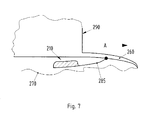
- Figure 7 shows an alternative exemplary embodiment of a sensor device 210, which is indicated here only diagrammatically, is flat overall and is arranged overall on the underside of a trough 290, again only indicated, with a machine track 260.
- the sensor device 210 can here be pivotably hinged on the underside of the machine track 260 via a pivot arm 285 and a pivot joint such that it is able as a rule to bear at any time against the surface, indicated by 270, of the mineral deposit because of the forces of gravity. Since no projecting sensor parts are present, there is no risk of shearing off at the sensor head.
- Sensors and/or sensor devices for integration in machine parts, in particular troughs for the mostly underground working of coal beds as mineral deposits are shown in all the exemplary embodiments.
- the shaping of the housing is therefore mostly adapted to be able to arrange the sensor devices in cylindrical receptacles.
- the shape of the housing can deviate fundamentally and be square, rectangular, round, flat etc. in design.
- the exemplary embodiments respectively show round sensor heads.
- the exemplary embodiments exclusively show sensor heads with electrodes which are distributed uniformly and/or symmetrically, since in the case of a uniform geometrical distribution of the electrodes, correspondingly uniformly arranged electrode pairs result which substantially simplify the complicated outlay on determining and ascertaining the apparent resistance. However, it would also be possible to arrange the electrodes non-uniformly, in which case the different spacings between the electrode pairs must be taken into account.
Landscapes
- Engineering & Computer Science (AREA)
- Life Sciences & Earth Sciences (AREA)
- Geology (AREA)
- Mining & Mineral Resources (AREA)
- General Life Sciences & Earth Sciences (AREA)
- Geochemistry & Mineralogy (AREA)
- Mechanical Engineering (AREA)
- Environmental & Geological Engineering (AREA)
- Remote Sensing (AREA)
- Physics & Mathematics (AREA)
- General Physics & Mathematics (AREA)
- Geophysics (AREA)
- Geophysics And Detection Of Objects (AREA)
- Investigating Or Analyzing Materials By The Use Of Electric Means (AREA)
Claims (15)
- Sensoreinrichtung für die geoelektrische Erkundung von mineralischen Rohstofflagerstätten insbesondere im laufenden Abbaubetrieb der Lagerstätten, wobei die Sensoreinrichtung aufweist:einen Sensorkopf (1; 51), dessen Frontfläche die Sensormessfläche (3; 53) bildet, wobei der Sensorkopf (1; 51) mit einer Bodenfläche kontaktierbar ist,eine Mittenelektrode (4; 54), die an der Sensormessfläche (3; 53) angeordnet ist, undmehrere Außenelektroden (5; 55), die geometrisch gleichmäßig verteilt um die Mittenelektrode (4; 54) an der Sensormessfläche (3; 53) angeordnet sind, wobei die Außenelektroden (5; 55) als Ringsegmentelektroden ausgebildet und ringförmig um die Mittenelektrode (4; 54) angeordnet sind, wobeidie Mittenelektrode (4; 54) und die Außenelektroden (5; 55) elektrisch leitfähig sind, elektrisch voneinander getrennt sind und Elektrodenpaare (4, 5; 5, 5; 54, 55; 55, 55) bilden, mit denen ein Potentialfeld aufgebaut wird.
- Sensoreinrichtung nach Anspruch 1, wobei die Mittenelektrode (4) an der Sensormessfläche (3) als Punktelektrode ausgebildet ist.
- Sensoreinrichtung nach Anspruch 1, wobei die Mittenelektrode (54) an der Sensormessfläche (53) als eine Ringelektrode ausgebildet ist.
- Sensoreinrichtung nach einem der Ansprüche 1 bis 3, wobei die Sensoreinrichtung (10) ein zylindrisches Gehäuse (10) mit Zylinderenden aufweist, wobei der Sensorkopf (1) an einem der Zylinderenden angeordnet ist, das Gehäuse (2) vorzugsweise mit einer Stufe (7) versehen ist, und der Stufenabsatz vorzugsweise eine Anlagefläche für eine Druckfeder bildet.
- Sensoreinrichtung nach einem der Ansprüche 1 bis 4, wobei die Ringsegmentelektroden an der Sensormessfläche (3) als Ringsegmentstege (6) ausgebildet sind, die sich an einer Frontfläche des Sensorkopfes (1) und an einer Mantelfläche des Sensorkopfes erstrecken, wobei die Außenelektroden (5) vorzugsweise am Übergang der Frontfläche in die Mantelfläche mit einer Fase (12) von vorzugsweise 45° versehen sind.
- Sensoreinrichtung nach Anspruch 5, wobei die Außenelektrode (5) an der Rückseite des Ringsegmentstegs (6) mit einer Kontaktleiste (16) versehen ist, die sich bis zu dem rückwärtigen Ende des Gehäuses erstreckt.
- Sensoreinrichtung nach Anspruch 4 oder einem der Ansprüche 5 oder 6, wobei das Gehäuse (2) mehrteilig aufgebaut ist und ein den Stufenabsatz aufweisendes Hinterteil (9) und ein Vorderteil (8), das mit dem Sensorkopf (1) versehen ist, umfasst, wobei die Gehäuseteile (8, 9) durch den Stufenabsatz hindurch miteinander verschraubbar sind, und vorzugsweise Zentrierzapfen (20) lösbar an dem Gehäuse (2) mit der Verschraubung befestigbar sind.
- Sensoreinrichtung nach einem der Ansprüche 1 bis 7, wobei das Radienverhältnis (r/R) zwischen dem Radius (r), der von den Innenelektroden (54) zu einer Mittelachse (M) gebildet ist, und dem Radius (R), der von den Außenelektroden (56) zu der Mittelachse gebildet ist, ungefähr 1/3 beträgt.
- Sensoreinrichtung nach einem der Ansprüche 1 bis 8, wobei die Außenelektroden einen Ring mit einem Ringdurchmesser von wenigstens 60 mm bilden, und/oder dass die Außenringelektroden eine Breite in der radialen Richtung von ungefähr 1/10 R aufweisen, und/oder dass der Abstand zwischen den zwei Außenelektroden, der mit Isolationsmaterial gefüllt ist, wenigstens 2 mm beträgt.
- Sensoreinrichtung nach einem der Ansprüche 1 bis 9, wobei die Sensoreinrichtung (10) an einem Rinnenelement (190; 290) einer untertägigen Gewinnungsanlage, insbesondere einer untertägigen Kohlengewinnungsanlage, einsetzbar ist, wobei vorzugsweise die Sensoreinrichtung in eine nach unten offene, zylindrische Ausnehmung (195) an dem Rinnenelement (190) einsetzbar ist und/oder der Sensorkopf (210) an einem Schwenkarm (285) angeordnet ist, der schwenkbar an der Unterseite des Rinnenelements (290) gelagert ist.
- Verfahren zur geoelektrischen Erkundung von mineralischen Rohstofflagerstätten im Erdboden insbesondere im laufenden Abbaubetrieb der Lagerstätten, wobei das Verfahren aufweist:Aufbauen eines Potentialfeldes in dem Erdboden mit einer Sensorvorrichtung (10), aufweisend:einen Sensorkopf (1; 51), dessen Frontfläche die Sensormessfläche (3; 53) bildet, wobei der Sensorkopf (1; 51) mit einer Oberfläche des Erdbodens kontaktierbar ist,eine Mittenelektrode (4; 54), die an der Sensormessfläche (3; 53) angeordnet ist, undmehrere Außenelektroden (5; 55), die geometrisch gleichmäßig um die Mittenelektrode (4; 54) an der Sensormessfläche (3; 53) verteilt angeordnet sind, wobei die Außenelektroden (5; 55) als Ringsegmentelektroden ausgebildet sind und ringförmig um die Mittenelektrode (4; 54) angeordnet sind, wobeidie Mittenelektrode (4; 54) und die Außenelektroden (5; 55) elektrisch leitfähig sind, elektrisch voneinander getrennt sind und Elektrodenpaare (4, 5; 5, 5; 54, 55; 55, 55) bilden, mit denen das Potentialfeld aufgebaut wird, undMessen des sich einstellenden Stroms.
- Verfahren nach Anspruch 11, wobei der Ersatzwiderstand zwischen allen Elektrodenpaaren (4, 5; 5, 5; 54, 55; 55, 55) des Sensorkopfes (1; 51) zur Erkundung des spezifischen Widerstands des Materials in dem Erdboden vor dem Sensorkopf (1; 51), der die Oberfläche des Erdbodens kontaktiert, gemessen wird.
- Verfahren nach Anspruch 11 oder 12, wobei zur Bestimmung der Oberfläche eine Änderung des Übergangswiderstandes zwischen den Elektroden des Elektrodenpaares (4, 5; 5, 5; 54, 55; 55, 55) während einer Bewegung des Sensorkopfes (1; 51) entlang der Oberfläche gemessen wird.
- Verfahren nach einem der Ansprüche 11 bis 13, wobei die Potenzialfelder oder der Übergangswiderstand bestimmt wird/werden, ohne mit dem Sensorkopf (1; 51) in den Erdboden einzudringen.
- Verfahren nach einem der Ansprüche 1 bis 14, wobei wenigstens zwei Elektroden zur Bildung einer Großelektrode kurzgeschlossen sind und/oder dass eine Sensoreinrichtung (10) gemäß einem der Ansprüche 1 bis 10 verwendet wird.
Priority Applications (1)
| Application Number | Priority Date | Filing Date | Title |
|---|---|---|---|
| PL10763436T PL2475844T3 (pl) | 2009-09-10 | 2010-09-03 | Urządzenie czujnikowe oraz sposób prowadzenia geoelektrycznych poszukiwań złóż surowców mineralnych |
Applications Claiming Priority (2)
| Application Number | Priority Date | Filing Date | Title |
|---|---|---|---|
| DE102009043972A DE102009043972A1 (de) | 2009-09-10 | 2009-09-10 | Sensoreinrichtung und Verfahren zur geoelektrischen Erkundung von mineralischen Rohstofflagerstätten |
| PCT/IB2010/053975 WO2011030268A2 (en) | 2009-09-10 | 2010-09-03 | Sensor device and method for the geoelectrical prospecting of raw mineral deposits |
Publications (2)
| Publication Number | Publication Date |
|---|---|
| EP2475844A2 EP2475844A2 (de) | 2012-07-18 |
| EP2475844B1 true EP2475844B1 (de) | 2015-02-25 |
Family
ID=43571156
Family Applications (1)
| Application Number | Title | Priority Date | Filing Date |
|---|---|---|---|
| EP10763436.2A Not-in-force EP2475844B1 (de) | 2009-09-10 | 2010-09-03 | Sensorvorrichtung und verfahren zur geoelektrischen untersuchung von rohmineralablagerungen |
Country Status (11)
| Country | Link |
|---|---|
| US (1) | US9051832B2 (de) |
| EP (1) | EP2475844B1 (de) |
| CN (1) | CN102498418B (de) |
| AU (1) | AU2010293860B2 (de) |
| CA (1) | CA2772203A1 (de) |
| DE (1) | DE102009043972A1 (de) |
| PL (1) | PL2475844T3 (de) |
| RU (1) | RU2541382C2 (de) |
| UA (1) | UA108621C2 (de) |
| WO (1) | WO2011030268A2 (de) |
| ZA (1) | ZA201202408B (de) |
Cited By (1)
| Publication number | Priority date | Publication date | Assignee | Title |
|---|---|---|---|---|
| CN106334928A (zh) * | 2015-07-14 | 2017-01-18 | 珠海益佳精密机械有限公司 | 精密弹簧装配及检测机构 |
Families Citing this family (7)
| Publication number | Priority date | Publication date | Assignee | Title |
|---|---|---|---|---|
| USD796971S1 (en) * | 2015-12-04 | 2017-09-12 | Sarl Xplorer | Metal detector |
| DE102019202379A1 (de) * | 2018-02-23 | 2019-08-29 | Frank Rinn | Vorrichtung und Verfahren zur Bestimmung von Materialeigenschaften eines Werkstoffs |
| US11329843B1 (en) | 2020-08-28 | 2022-05-10 | Earthsystems Technologies, Inc. | Method for multichannel acquisition of geophysical data and system implementation |
| US11808797B1 (en) | 2021-03-19 | 2023-11-07 | Earthsystems Technologies, Inc. | Hemispherical dome electrode configuration and method of use |
| CN112965117B (zh) * | 2021-04-08 | 2024-09-27 | 桂林理工大学 | 一种水层覆盖下地电提取装置及方法 |
| CN112946763A (zh) * | 2021-04-08 | 2021-06-11 | 桂林理工大学 | 一种封装式地电提取电极及使用方法 |
| CN117940765A (zh) * | 2021-09-08 | 2024-04-26 | 音羽电机工业株式会社 | 能测量电场强度的传感器装置及测量外部电场的方法 |
Family Cites Families (33)
| Publication number | Priority date | Publication date | Assignee | Title |
|---|---|---|---|---|
| SU217318A1 (ru) * | 1966-12-12 | 1986-06-30 | Восточный Геофизический Трест | Устройство дл дивергентного микрокаротажа скважин |
| FR2082202A5 (de) * | 1970-03-06 | 1971-12-10 | Schlumberger Prospection | |
| US3828242A (en) * | 1972-07-18 | 1974-08-06 | R Vann | Electromagnetic induction exploration guide assembly |
| US3970927A (en) * | 1973-11-30 | 1976-07-20 | Plessey Handel Und Investments A.G. | Method and apparatus including a sensing head with a pair of strip transmission lines for detecting metallic objects |
| US4199720A (en) * | 1978-07-27 | 1980-04-22 | Mcneill J Duncan | Method for investigating the conductivity of layered terrain |
| FR2463939A1 (fr) | 1979-08-17 | 1981-02-27 | Inst Francais Du Petrole | Perfectionnement a la methode et aux dispositifs de mesure de la resistivite electrique de formations geologiques |
| US4468623A (en) | 1981-07-30 | 1984-08-28 | Schlumberger Technology Corporation | Method and apparatus using pad carrying electrodes for electrically investigating a borehole |
| SU1101716A1 (ru) * | 1983-03-31 | 1984-07-07 | Институт Горного Дела Со Ан Ссср | Электрометрический зонд |
| JPS6388487A (ja) * | 1986-10-01 | 1988-04-19 | Komatsu Ltd | シ−ルド掘削機における切羽部の異常検出方法 |
| CH673798A5 (de) * | 1987-02-03 | 1990-04-12 | Charmilles Technologies | |
| FR2643465B1 (fr) * | 1989-02-20 | 1991-05-24 | Schlumberger Prospection | Procede et dispositif pour mesurer la resistivite des formations geologiques |
| ATE104719T1 (de) * | 1990-12-14 | 1994-05-15 | Servoindikator Hb | Anzeiger. |
| JPH05293520A (ja) | 1992-04-20 | 1993-11-09 | Toshiba Corp | 圧延制御装置 |
| JP3276550B2 (ja) * | 1995-12-19 | 2002-04-22 | シスメックス株式会社 | 試料定量装置 |
| EP0791824A2 (de) * | 1996-02-21 | 1997-08-27 | Osaka Gas Co., Ltd. | Verfahren zur Herstellung eines Stickstoffoxidsensors, und so hergestellter Stickstoffoxidsensor sowie Material dafür |
| DE19627312C1 (de) | 1996-06-25 | 1997-11-13 | Reinhold Wiechern Mestechnik U | Kanal-Fräsroboter |
| EP1736771A3 (de) * | 2000-07-13 | 2007-03-21 | National Research Institute For Earth Science And Disaster Prevention | Stabelektrode zum Messen der Leitfähigkeit oder des Widerstandes |
| US6541977B2 (en) * | 2001-02-13 | 2003-04-01 | Pulsar 2000, Inc. | Electronic water line tracer |
| US6853937B2 (en) * | 2001-07-06 | 2005-02-08 | Tokyo University Of Agriculture And Technology Tlo Co., Ltd. | Soil characteristics survey device and soil characteristics survey method |
| US6963205B2 (en) * | 2002-08-21 | 2005-11-08 | Lundstrom John W | Electrically measuring soil dry density |
| US7023213B2 (en) * | 2002-12-10 | 2006-04-04 | Schlumberger Technology Corporation | Subsurface conductivity imaging systems and methods |
| AU2003902609A0 (en) * | 2003-05-27 | 2003-06-12 | The University Of Queensland | Blast movement monitor |
| JP3646221B2 (ja) * | 2003-06-30 | 2005-05-11 | 財団法人北九州産業学術推進機構 | 位置・姿勢変化に対応する電気信号発生装置 |
| WO2005015262A1 (ja) * | 2003-07-16 | 2005-02-17 | Canon Kabushiki Kaisha | 地中探査装置、システム及び方法 |
| CN1252492C (zh) * | 2003-12-25 | 2006-04-19 | 周仁安 | 大地电磁波电阻率测量方法及其仪器 |
| US6975121B2 (en) * | 2004-03-22 | 2005-12-13 | Kjt Enterprises, Inc. | System for measuring earth formation resistivity through and electrically conductive wellbore casing |
| US7183777B2 (en) * | 2005-01-19 | 2007-02-27 | Her Majesty The Queen In Right Of Canada, As Represented By The Minister Of Natural Resources | Integrated capacitive sensor system for the measurement of resistivity and dielectric constant in geophysical, environmental, groundwater and related applications |
| CN101142470A (zh) * | 2005-03-18 | 2008-03-12 | 新田株式会社 | 静电电容式传感器 |
| US8154280B2 (en) * | 2006-11-30 | 2012-04-10 | Asahi Kasei Kabushiki Kaisha | Thin film lamination, thin film magnetic sensor using the thin film lamination and method for manufacturing the thin film lamination |
| DE202006018980U1 (de) * | 2006-12-15 | 2007-04-12 | Herrenknecht Ag | Bohrvorrichtung |
| US20080297169A1 (en) * | 2007-05-31 | 2008-12-04 | Greenquist Alfred C | Particle Fraction Determination of A Sample |
| DE102007029782A1 (de) | 2007-06-21 | 2008-12-24 | Dreiucker, Wolfgang, Dipl.-Ing. | Verfahren zur geologischen Erkundung von mineralischen Rohstofflagerstätten in Verwitterungslagen |
| US8115367B2 (en) * | 2007-11-26 | 2012-02-14 | Sii Nanotechnology Inc. | Piezoelectric actuator provided with a displacement meter, piezoelectric element, and positioning device |
-
2009
- 2009-09-10 DE DE102009043972A patent/DE102009043972A1/de not_active Withdrawn
-
2010
- 2010-09-03 WO PCT/IB2010/053975 patent/WO2011030268A2/en not_active Ceased
- 2010-09-03 CN CN201080040062.5A patent/CN102498418B/zh not_active Expired - Fee Related
- 2010-09-03 RU RU2012113808/28A patent/RU2541382C2/ru not_active IP Right Cessation
- 2010-09-03 EP EP10763436.2A patent/EP2475844B1/de not_active Not-in-force
- 2010-09-03 PL PL10763436T patent/PL2475844T3/pl unknown
- 2010-09-03 CA CA2772203A patent/CA2772203A1/en not_active Abandoned
- 2010-09-03 US US13/395,065 patent/US9051832B2/en active Active
- 2010-09-03 AU AU2010293860A patent/AU2010293860B2/en not_active Ceased
- 2010-09-03 UA UAA201204489A patent/UA108621C2/uk unknown
-
2012
- 2012-04-03 ZA ZA2012/02408A patent/ZA201202408B/en unknown
Cited By (2)
| Publication number | Priority date | Publication date | Assignee | Title |
|---|---|---|---|---|
| CN106334928A (zh) * | 2015-07-14 | 2017-01-18 | 珠海益佳精密机械有限公司 | 精密弹簧装配及检测机构 |
| CN106334928B (zh) * | 2015-07-14 | 2019-01-18 | 珠海益佳精密机械有限公司 | 精密弹簧装配及检测机构 |
Also Published As
| Publication number | Publication date |
|---|---|
| WO2011030268A3 (en) | 2011-06-23 |
| WO2011030268A2 (en) | 2011-03-17 |
| PL2475844T3 (pl) | 2015-07-31 |
| UA108621C2 (uk) | 2015-05-25 |
| AU2010293860B2 (en) | 2015-06-25 |
| AU2010293860A1 (en) | 2012-03-15 |
| ZA201202408B (en) | 2012-12-27 |
| US9051832B2 (en) | 2015-06-09 |
| RU2541382C2 (ru) | 2015-02-10 |
| CN102498418A (zh) | 2012-06-13 |
| EP2475844A2 (de) | 2012-07-18 |
| CN102498418B (zh) | 2016-02-03 |
| CA2772203A1 (en) | 2011-03-17 |
| DE102009043972A1 (de) | 2011-03-17 |
| US20120182016A1 (en) | 2012-07-19 |
| RU2012113808A (ru) | 2013-10-27 |
Similar Documents
| Publication | Publication Date | Title |
|---|---|---|
| US9051832B2 (en) | Sensor device and method for the geoelectrical prospecting of raw mineral deposits | |
| Singh et al. | Multielectrode resistivity imaging technique for the study of coal seam | |
| Parra et al. | Model studies of electrical leak detection surveys in geomembrane-lined impoundments | |
| US6731114B1 (en) | Apparatus with capacitive electrodes for measuring subsurface electrical characteristics in the subsoil | |
| GAO et al. | Research and application of the 3D DC resistivity method with around working face | |
| Bernard et al. | Multi-electrode resistivity imaging for environmental and mining applications | |
| CN113504572A (zh) | 一种增强音频电透视法检测工作面底板注浆效果的方法 | |
| Benderitter et al. | Application of the electrostatic quadripole to sounding in the hectometric depth range | |
| Hauck et al. | Using DC resistivity tomography to detect and characterise mountain permafrost | |
| Christopher et al. | Characterization of landslides: a preliminary vertical electrical sounding approach | |
| Stierman et al. | Electrical resistivity mapping of landscape modifications at the Talgua site, Olancho, Honduras | |
| Mwenifumbo | Electrical methods for ore body delineation | |
| Naudet et al. | 3D electrical resistivity tomography to locate DNAPL contamination in an urban environment | |
| Chambers et al. | Characterising sand and gravel deposits using electrical resistivity tomography (ERT): case histories from England and Wales | |
| Ezeh et al. | 2D electrical resistivity imaging of fracture zones in Isu-Awaa, Enugu State, Southeastern Nigeria | |
| RU2021506C1 (ru) | Способ геоэлектроразведки для прогноза участков неоднородной кровли угольных пластов | |
| Kang et al. | Laboratory experiments for hazardous ground prediction ahead of a TBM tunnel face based on resistivity and induced polarization | |
| Abdullahi et al. | Application of geo-electrical imaging to determine signatures of buried waste | |
| Apostolopoulos et al. | Resistivity arrays in the detection of buried bodies | |
| SU1287077A1 (ru) | Способ геоэлектроразведки методом зар да | |
| Candansayar et al. | Investigation of landslide by using 2D/3D resistivity imaging | |
| Dixon et al. | Some Shallow Earth-Resistivity Measurements in Iowa | |
| LeBel | An evaluation of the performance and applicability of battery induced polarization systems | |
| Asry et al. | Electrical resistivity imaging and bedrock elevation in UPM, Serdang, Malaysia | |
| Cho et al. | Prediction of ground-condition ahead of tunnel face using electric resistivity-analytical study |
Legal Events
| Date | Code | Title | Description |
|---|---|---|---|
| PUAI | Public reference made under article 153(3) epc to a published international application that has entered the european phase |
Free format text: ORIGINAL CODE: 0009012 |
|
| 17P | Request for examination filed |
Effective date: 20120323 |
|
| AK | Designated contracting states |
Kind code of ref document: A2 Designated state(s): AL AT BE BG CH CY CZ DE DK EE ES FI FR GB GR HR HU IE IS IT LI LT LU LV MC MK MT NL NO PL PT RO SE SI SK SM TR |
|
| DAX | Request for extension of the european patent (deleted) | ||
| 17Q | First examination report despatched |
Effective date: 20140422 |
|
| GRAP | Despatch of communication of intention to grant a patent |
Free format text: ORIGINAL CODE: EPIDOSNIGR1 |
|
| INTG | Intention to grant announced |
Effective date: 20141008 |
|
| GRAS | Grant fee paid |
Free format text: ORIGINAL CODE: EPIDOSNIGR3 |
|
| GRAA | (expected) grant |
Free format text: ORIGINAL CODE: 0009210 |
|
| AK | Designated contracting states |
Kind code of ref document: B1 Designated state(s): AL AT BE BG CH CY CZ DE DK EE ES FI FR GB GR HR HU IE IS IT LI LT LU LV MC MK MT NL NO PL PT RO SE SI SK SM TR |
|
| REG | Reference to a national code |
Ref country code: GB Ref legal event code: FG4D |
|
| REG | Reference to a national code |
Ref country code: CH Ref legal event code: EP |
|
| REG | Reference to a national code |
Ref country code: IE Ref legal event code: FG4D |
|
| REG | Reference to a national code |
Ref country code: DE Ref legal event code: R096 Ref document number: 602010022591 Country of ref document: DE Effective date: 20150409 |
|
| REG | Reference to a national code |
Ref country code: AT Ref legal event code: REF Ref document number: 712170 Country of ref document: AT Kind code of ref document: T Effective date: 20150415 |
|
| REG | Reference to a national code |
Ref country code: NL Ref legal event code: VDEP Effective date: 20150225 |
|
| REG | Reference to a national code |
Ref country code: AT Ref legal event code: MK05 Ref document number: 712170 Country of ref document: AT Kind code of ref document: T Effective date: 20150225 |
|
| REG | Reference to a national code |
Ref country code: LT Ref legal event code: MG4D |
|
| PG25 | Lapsed in a contracting state [announced via postgrant information from national office to epo] |
Ref country code: HR Free format text: LAPSE BECAUSE OF FAILURE TO SUBMIT A TRANSLATION OF THE DESCRIPTION OR TO PAY THE FEE WITHIN THE PRESCRIBED TIME-LIMIT Effective date: 20150225 Ref country code: SE Free format text: LAPSE BECAUSE OF FAILURE TO SUBMIT A TRANSLATION OF THE DESCRIPTION OR TO PAY THE FEE WITHIN THE PRESCRIBED TIME-LIMIT Effective date: 20150225 Ref country code: FI Free format text: LAPSE BECAUSE OF FAILURE TO SUBMIT A TRANSLATION OF THE DESCRIPTION OR TO PAY THE FEE WITHIN THE PRESCRIBED TIME-LIMIT Effective date: 20150225 Ref country code: NO Free format text: LAPSE BECAUSE OF FAILURE TO SUBMIT A TRANSLATION OF THE DESCRIPTION OR TO PAY THE FEE WITHIN THE PRESCRIBED TIME-LIMIT Effective date: 20150525 Ref country code: ES Free format text: LAPSE BECAUSE OF FAILURE TO SUBMIT A TRANSLATION OF THE DESCRIPTION OR TO PAY THE FEE WITHIN THE PRESCRIBED TIME-LIMIT Effective date: 20150225 Ref country code: LT Free format text: LAPSE BECAUSE OF FAILURE TO SUBMIT A TRANSLATION OF THE DESCRIPTION OR TO PAY THE FEE WITHIN THE PRESCRIBED TIME-LIMIT Effective date: 20150225 |
|
| REG | Reference to a national code |
Ref country code: PL Ref legal event code: T3 |
|
| PG25 | Lapsed in a contracting state [announced via postgrant information from national office to epo] |
Ref country code: GR Free format text: LAPSE BECAUSE OF FAILURE TO SUBMIT A TRANSLATION OF THE DESCRIPTION OR TO PAY THE FEE WITHIN THE PRESCRIBED TIME-LIMIT Effective date: 20150526 Ref country code: LV Free format text: LAPSE BECAUSE OF FAILURE TO SUBMIT A TRANSLATION OF THE DESCRIPTION OR TO PAY THE FEE WITHIN THE PRESCRIBED TIME-LIMIT Effective date: 20150225 Ref country code: IS Free format text: LAPSE BECAUSE OF FAILURE TO SUBMIT A TRANSLATION OF THE DESCRIPTION OR TO PAY THE FEE WITHIN THE PRESCRIBED TIME-LIMIT Effective date: 20150625 Ref country code: AT Free format text: LAPSE BECAUSE OF FAILURE TO SUBMIT A TRANSLATION OF THE DESCRIPTION OR TO PAY THE FEE WITHIN THE PRESCRIBED TIME-LIMIT Effective date: 20150225 |
|
| PG25 | Lapsed in a contracting state [announced via postgrant information from national office to epo] |
Ref country code: NL Free format text: LAPSE BECAUSE OF FAILURE TO SUBMIT A TRANSLATION OF THE DESCRIPTION OR TO PAY THE FEE WITHIN THE PRESCRIBED TIME-LIMIT Effective date: 20150225 |
|
| PG25 | Lapsed in a contracting state [announced via postgrant information from national office to epo] |
Ref country code: SK Free format text: LAPSE BECAUSE OF FAILURE TO SUBMIT A TRANSLATION OF THE DESCRIPTION OR TO PAY THE FEE WITHIN THE PRESCRIBED TIME-LIMIT Effective date: 20150225 Ref country code: RO Free format text: LAPSE BECAUSE OF FAILURE TO SUBMIT A TRANSLATION OF THE DESCRIPTION OR TO PAY THE FEE WITHIN THE PRESCRIBED TIME-LIMIT Effective date: 20150225 Ref country code: EE Free format text: LAPSE BECAUSE OF FAILURE TO SUBMIT A TRANSLATION OF THE DESCRIPTION OR TO PAY THE FEE WITHIN THE PRESCRIBED TIME-LIMIT Effective date: 20150225 Ref country code: DK Free format text: LAPSE BECAUSE OF FAILURE TO SUBMIT A TRANSLATION OF THE DESCRIPTION OR TO PAY THE FEE WITHIN THE PRESCRIBED TIME-LIMIT Effective date: 20150225 |
|
| PGFP | Annual fee paid to national office [announced via postgrant information from national office to epo] |
Ref country code: CZ Payment date: 20150828 Year of fee payment: 6 |
|
| REG | Reference to a national code |
Ref country code: DE Ref legal event code: R097 Ref document number: 602010022591 Country of ref document: DE |
|
| PG25 | Lapsed in a contracting state [announced via postgrant information from national office to epo] |
Ref country code: IT Free format text: LAPSE BECAUSE OF FAILURE TO SUBMIT A TRANSLATION OF THE DESCRIPTION OR TO PAY THE FEE WITHIN THE PRESCRIBED TIME-LIMIT Effective date: 20150225 |
|
| PLBE | No opposition filed within time limit |
Free format text: ORIGINAL CODE: 0009261 |
|
| STAA | Information on the status of an ep patent application or granted ep patent |
Free format text: STATUS: NO OPPOSITION FILED WITHIN TIME LIMIT |
|
| 26N | No opposition filed |
Effective date: 20151126 |
|
| PG25 | Lapsed in a contracting state [announced via postgrant information from national office to epo] |
Ref country code: SI Free format text: LAPSE BECAUSE OF FAILURE TO SUBMIT A TRANSLATION OF THE DESCRIPTION OR TO PAY THE FEE WITHIN THE PRESCRIBED TIME-LIMIT Effective date: 20150225 |
|
| PG25 | Lapsed in a contracting state [announced via postgrant information from national office to epo] |
Ref country code: LU Free format text: LAPSE BECAUSE OF FAILURE TO SUBMIT A TRANSLATION OF THE DESCRIPTION OR TO PAY THE FEE WITHIN THE PRESCRIBED TIME-LIMIT Effective date: 20150903 Ref country code: MC Free format text: LAPSE BECAUSE OF FAILURE TO SUBMIT A TRANSLATION OF THE DESCRIPTION OR TO PAY THE FEE WITHIN THE PRESCRIBED TIME-LIMIT Effective date: 20150225 |
|
| REG | Reference to a national code |
Ref country code: CH Ref legal event code: PL |
|
| GBPC | Gb: european patent ceased through non-payment of renewal fee |
Effective date: 20150903 |
|
| PG25 | Lapsed in a contracting state [announced via postgrant information from national office to epo] |
Ref country code: BE Free format text: LAPSE BECAUSE OF FAILURE TO SUBMIT A TRANSLATION OF THE DESCRIPTION OR TO PAY THE FEE WITHIN THE PRESCRIBED TIME-LIMIT Effective date: 20150225 |
|
| REG | Reference to a national code |
Ref country code: IE Ref legal event code: MM4A |
|
| REG | Reference to a national code |
Ref country code: FR Ref legal event code: ST Effective date: 20160531 |
|
| PG25 | Lapsed in a contracting state [announced via postgrant information from national office to epo] |
Ref country code: IE Free format text: LAPSE BECAUSE OF NON-PAYMENT OF DUE FEES Effective date: 20150903 Ref country code: CH Free format text: LAPSE BECAUSE OF NON-PAYMENT OF DUE FEES Effective date: 20150930 Ref country code: GB Free format text: LAPSE BECAUSE OF NON-PAYMENT OF DUE FEES Effective date: 20150903 Ref country code: LI Free format text: LAPSE BECAUSE OF NON-PAYMENT OF DUE FEES Effective date: 20150930 |
|
| PG25 | Lapsed in a contracting state [announced via postgrant information from national office to epo] |
Ref country code: FR Free format text: LAPSE BECAUSE OF NON-PAYMENT OF DUE FEES Effective date: 20150930 |
|
| PGFP | Annual fee paid to national office [announced via postgrant information from national office to epo] |
Ref country code: DE Payment date: 20160928 Year of fee payment: 7 |
|
| PG25 | Lapsed in a contracting state [announced via postgrant information from national office to epo] |
Ref country code: MT Free format text: LAPSE BECAUSE OF FAILURE TO SUBMIT A TRANSLATION OF THE DESCRIPTION OR TO PAY THE FEE WITHIN THE PRESCRIBED TIME-LIMIT Effective date: 20150225 |
|
| PG25 | Lapsed in a contracting state [announced via postgrant information from national office to epo] |
Ref country code: BG Free format text: LAPSE BECAUSE OF FAILURE TO SUBMIT A TRANSLATION OF THE DESCRIPTION OR TO PAY THE FEE WITHIN THE PRESCRIBED TIME-LIMIT Effective date: 20150225 Ref country code: SM Free format text: LAPSE BECAUSE OF FAILURE TO SUBMIT A TRANSLATION OF THE DESCRIPTION OR TO PAY THE FEE WITHIN THE PRESCRIBED TIME-LIMIT Effective date: 20150225 Ref country code: CZ Free format text: LAPSE BECAUSE OF NON-PAYMENT OF DUE FEES Effective date: 20160903 Ref country code: HU Free format text: LAPSE BECAUSE OF FAILURE TO SUBMIT A TRANSLATION OF THE DESCRIPTION OR TO PAY THE FEE WITHIN THE PRESCRIBED TIME-LIMIT; INVALID AB INITIO Effective date: 20100903 |
|
| PG25 | Lapsed in a contracting state [announced via postgrant information from national office to epo] |
Ref country code: CY Free format text: LAPSE BECAUSE OF FAILURE TO SUBMIT A TRANSLATION OF THE DESCRIPTION OR TO PAY THE FEE WITHIN THE PRESCRIBED TIME-LIMIT Effective date: 20150225 |
|
| PG25 | Lapsed in a contracting state [announced via postgrant information from national office to epo] |
Ref country code: TR Free format text: LAPSE BECAUSE OF FAILURE TO SUBMIT A TRANSLATION OF THE DESCRIPTION OR TO PAY THE FEE WITHIN THE PRESCRIBED TIME-LIMIT Effective date: 20150225 |
|
| REG | Reference to a national code |
Ref country code: DE Ref legal event code: R119 Ref document number: 602010022591 Country of ref document: DE |
|
| PG25 | Lapsed in a contracting state [announced via postgrant information from national office to epo] |
Ref country code: PT Free format text: LAPSE BECAUSE OF FAILURE TO SUBMIT A TRANSLATION OF THE DESCRIPTION OR TO PAY THE FEE WITHIN THE PRESCRIBED TIME-LIMIT Effective date: 20150225 Ref country code: MK Free format text: LAPSE BECAUSE OF FAILURE TO SUBMIT A TRANSLATION OF THE DESCRIPTION OR TO PAY THE FEE WITHIN THE PRESCRIBED TIME-LIMIT Effective date: 20150225 |
|
| PG25 | Lapsed in a contracting state [announced via postgrant information from national office to epo] |
Ref country code: DE Free format text: LAPSE BECAUSE OF NON-PAYMENT OF DUE FEES Effective date: 20180404 |
|
| PG25 | Lapsed in a contracting state [announced via postgrant information from national office to epo] |
Ref country code: AL Free format text: LAPSE BECAUSE OF FAILURE TO SUBMIT A TRANSLATION OF THE DESCRIPTION OR TO PAY THE FEE WITHIN THE PRESCRIBED TIME-LIMIT Effective date: 20150225 |
|
| PGFP | Annual fee paid to national office [announced via postgrant information from national office to epo] |
Ref country code: PL Payment date: 20190819 Year of fee payment: 10 |
|
| PG25 | Lapsed in a contracting state [announced via postgrant information from national office to epo] |
Ref country code: PL Free format text: LAPSE BECAUSE OF NON-PAYMENT OF DUE FEES Effective date: 20200903 |