EP2475335B1 - Medizinisches implantat - Google Patents
Medizinisches implantat Download PDFInfo
- Publication number
- EP2475335B1 EP2475335B1 EP10755108.7A EP10755108A EP2475335B1 EP 2475335 B1 EP2475335 B1 EP 2475335B1 EP 10755108 A EP10755108 A EP 10755108A EP 2475335 B1 EP2475335 B1 EP 2475335B1
- Authority
- EP
- European Patent Office
- Prior art keywords
- cell
- lattice structure
- webs
- cells
- stent
- Prior art date
- Legal status (The legal status is an assumption and is not a legal conclusion. Google has not performed a legal analysis and makes no representation as to the accuracy of the status listed.)
- Active
Links
Images





Classifications
-
- A—HUMAN NECESSITIES
- A61—MEDICAL OR VETERINARY SCIENCE; HYGIENE
- A61F—FILTERS IMPLANTABLE INTO BLOOD VESSELS; PROSTHESES; DEVICES PROVIDING PATENCY TO, OR PREVENTING COLLAPSING OF, TUBULAR STRUCTURES OF THE BODY, e.g. STENTS; ORTHOPAEDIC, NURSING OR CONTRACEPTIVE DEVICES; FOMENTATION; TREATMENT OR PROTECTION OF EYES OR EARS; BANDAGES, DRESSINGS OR ABSORBENT PADS; FIRST-AID KITS
- A61F2/00—Filters implantable into blood vessels; Prostheses, i.e. artificial substitutes or replacements for parts of the body; Appliances for connecting them with the body; Devices providing patency to, or preventing collapsing of, tubular structures of the body, e.g. stents
- A61F2/82—Devices providing patency to, or preventing collapsing of, tubular structures of the body, e.g. stents
- A61F2/86—Stents in a form characterised by the wire-like elements; Stents in the form characterised by a net-like or mesh-like structure
- A61F2/90—Stents in a form characterised by the wire-like elements; Stents in the form characterised by a net-like or mesh-like structure characterised by a net-like or mesh-like structure
- A61F2/91—Stents in a form characterised by the wire-like elements; Stents in the form characterised by a net-like or mesh-like structure characterised by a net-like or mesh-like structure made from perforated sheets or tubes, e.g. perforated by laser cuts or etched holes
- A61F2/915—Stents in a form characterised by the wire-like elements; Stents in the form characterised by a net-like or mesh-like structure characterised by a net-like or mesh-like structure made from perforated sheets or tubes, e.g. perforated by laser cuts or etched holes with bands having a meander structure, adjacent bands being connected to each other
-
- A—HUMAN NECESSITIES
- A61—MEDICAL OR VETERINARY SCIENCE; HYGIENE
- A61F—FILTERS IMPLANTABLE INTO BLOOD VESSELS; PROSTHESES; DEVICES PROVIDING PATENCY TO, OR PREVENTING COLLAPSING OF, TUBULAR STRUCTURES OF THE BODY, e.g. STENTS; ORTHOPAEDIC, NURSING OR CONTRACEPTIVE DEVICES; FOMENTATION; TREATMENT OR PROTECTION OF EYES OR EARS; BANDAGES, DRESSINGS OR ABSORBENT PADS; FIRST-AID KITS
- A61F2/00—Filters implantable into blood vessels; Prostheses, i.e. artificial substitutes or replacements for parts of the body; Appliances for connecting them with the body; Devices providing patency to, or preventing collapsing of, tubular structures of the body, e.g. stents
- A61F2/82—Devices providing patency to, or preventing collapsing of, tubular structures of the body, e.g. stents
- A61F2/848—Devices providing patency to, or preventing collapsing of, tubular structures of the body, e.g. stents having means for fixation to the vessel wall, e.g. barbs
-
- A—HUMAN NECESSITIES
- A61—MEDICAL OR VETERINARY SCIENCE; HYGIENE
- A61F—FILTERS IMPLANTABLE INTO BLOOD VESSELS; PROSTHESES; DEVICES PROVIDING PATENCY TO, OR PREVENTING COLLAPSING OF, TUBULAR STRUCTURES OF THE BODY, e.g. STENTS; ORTHOPAEDIC, NURSING OR CONTRACEPTIVE DEVICES; FOMENTATION; TREATMENT OR PROTECTION OF EYES OR EARS; BANDAGES, DRESSINGS OR ABSORBENT PADS; FIRST-AID KITS
- A61F2/00—Filters implantable into blood vessels; Prostheses, i.e. artificial substitutes or replacements for parts of the body; Appliances for connecting them with the body; Devices providing patency to, or preventing collapsing of, tubular structures of the body, e.g. stents
- A61F2/82—Devices providing patency to, or preventing collapsing of, tubular structures of the body, e.g. stents
- A61F2/86—Stents in a form characterised by the wire-like elements; Stents in the form characterised by a net-like or mesh-like structure
- A61F2/90—Stents in a form characterised by the wire-like elements; Stents in the form characterised by a net-like or mesh-like structure characterised by a net-like or mesh-like structure
- A61F2/91—Stents in a form characterised by the wire-like elements; Stents in the form characterised by a net-like or mesh-like structure characterised by a net-like or mesh-like structure made from perforated sheets or tubes, e.g. perforated by laser cuts or etched holes
-
- A—HUMAN NECESSITIES
- A61—MEDICAL OR VETERINARY SCIENCE; HYGIENE
- A61F—FILTERS IMPLANTABLE INTO BLOOD VESSELS; PROSTHESES; DEVICES PROVIDING PATENCY TO, OR PREVENTING COLLAPSING OF, TUBULAR STRUCTURES OF THE BODY, e.g. STENTS; ORTHOPAEDIC, NURSING OR CONTRACEPTIVE DEVICES; FOMENTATION; TREATMENT OR PROTECTION OF EYES OR EARS; BANDAGES, DRESSINGS OR ABSORBENT PADS; FIRST-AID KITS
- A61F2220/00—Fixations or connections for prostheses classified in groups A61F2/00 - A61F2/26 or A61F2/82 or A61F9/00 or A61F11/00 or subgroups thereof
- A61F2220/0008—Fixation appliances for connecting prostheses to the body
-
- A—HUMAN NECESSITIES
- A61—MEDICAL OR VETERINARY SCIENCE; HYGIENE
- A61F—FILTERS IMPLANTABLE INTO BLOOD VESSELS; PROSTHESES; DEVICES PROVIDING PATENCY TO, OR PREVENTING COLLAPSING OF, TUBULAR STRUCTURES OF THE BODY, e.g. STENTS; ORTHOPAEDIC, NURSING OR CONTRACEPTIVE DEVICES; FOMENTATION; TREATMENT OR PROTECTION OF EYES OR EARS; BANDAGES, DRESSINGS OR ABSORBENT PADS; FIRST-AID KITS
- A61F2230/00—Geometry of prostheses classified in groups A61F2/00 - A61F2/26 or A61F2/82 or A61F9/00 or A61F11/00 or subgroups thereof
- A61F2230/0002—Two-dimensional shapes, e.g. cross-sections
- A61F2230/0004—Rounded shapes, e.g. with rounded corners
- A61F2230/0013—Horseshoe-shaped, e.g. crescent-shaped, C-shaped, U-shaped
-
- A—HUMAN NECESSITIES
- A61—MEDICAL OR VETERINARY SCIENCE; HYGIENE
- A61F—FILTERS IMPLANTABLE INTO BLOOD VESSELS; PROSTHESES; DEVICES PROVIDING PATENCY TO, OR PREVENTING COLLAPSING OF, TUBULAR STRUCTURES OF THE BODY, e.g. STENTS; ORTHOPAEDIC, NURSING OR CONTRACEPTIVE DEVICES; FOMENTATION; TREATMENT OR PROTECTION OF EYES OR EARS; BANDAGES, DRESSINGS OR ABSORBENT PADS; FIRST-AID KITS
- A61F2230/00—Geometry of prostheses classified in groups A61F2/00 - A61F2/26 or A61F2/82 or A61F9/00 or A61F11/00 or subgroups thereof
- A61F2230/0002—Two-dimensional shapes, e.g. cross-sections
- A61F2230/0028—Shapes in the form of latin or greek characters
- A61F2230/0054—V-shaped
-
- A—HUMAN NECESSITIES
- A61—MEDICAL OR VETERINARY SCIENCE; HYGIENE
- A61F—FILTERS IMPLANTABLE INTO BLOOD VESSELS; PROSTHESES; DEVICES PROVIDING PATENCY TO, OR PREVENTING COLLAPSING OF, TUBULAR STRUCTURES OF THE BODY, e.g. STENTS; ORTHOPAEDIC, NURSING OR CONTRACEPTIVE DEVICES; FOMENTATION; TREATMENT OR PROTECTION OF EYES OR EARS; BANDAGES, DRESSINGS OR ABSORBENT PADS; FIRST-AID KITS
- A61F2250/00—Special features of prostheses classified in groups A61F2/00 - A61F2/26 or A61F2/82 or A61F9/00 or A61F11/00 or subgroups thereof
- A61F2250/0058—Additional features; Implant or prostheses properties not otherwise provided for
- A61F2250/0096—Markers and sensors for detecting a position or changes of a position of an implant, e.g. RF sensors, ultrasound markers
- A61F2250/0098—Markers and sensors for detecting a position or changes of a position of an implant, e.g. RF sensors, ultrasound markers radio-opaque, e.g. radio-opaque markers
Definitions
- the invention relates to a medical implant having a wall which comprises a lattice structure which can be converted from a compressed to an expanded state and formed from first webs, wherein the lattice structure has closed cells each with a holding element which is adapted for anchoring the expanded lattice structure in a vessel ,
- a medical implant having a wall which comprises a lattice structure which can be converted from a compressed to an expanded state and formed from first webs, wherein the lattice structure has closed cells each with a holding element which is adapted for anchoring the expanded lattice structure in a vessel ,
- Such an implant is for example off US 5,397,355 known.
- the coil catheter can get caught in the tips of the cells, so that - with insufficient anchoring of the stent in the blood vessel - the stent can slip.
- stents in the blood vessel may be due to a too low radially outward force or to the shape of the cell geometry.
- weaknesses in the adaptation to the anatomical conditions in the neurocerebral vascular system in known stent systems are frequently to be observed.
- a stent with an open cell design is in US 2005/0143801 A1 described.
- the stent on hook elements which serve to fix a cover on the stent (stent-graft). Retraction of the stent into a catheter, for example, to correct for mispositioning, is not possible because the hook elements become entangled upon retraction of the stent at the catheter tip.
- the stent according to US 5,397,355 has a grid structure formed of webs, which can be converted from a compressed to an expanded state.
- the lattice structure is formed of closed cells (closed cell design).
- the cells To anchor the expanded lattice structure in a vessel, the cells each have a retaining element which is moved radially outward in the expanded state and projects beyond the wall of the stent.
- the holding element is designed as a spike with a sharp tip, which drills into the vessel wall in the implanted state. This can lead to injuries.
- US 5,330,500 discloses which, similar to the known stent described above has hook-shaped tips in the cells that drill in the implanted state in the vessel wall.
- US 5,800,526 describes a stent with an anchoring system, in which the lattice structure is formed so that it partially projects in the implanted state over the wall of the stent and fixes the stent against dislocation.
- the stent is not a closed cell design, but an open cell design that has the disadvantage that it can not be pulled back into the catheter after it has been released.
- US 2006/0100695 A1 which has a lattice structure formed partly of closed and partly open cells.
- the stent has a drug-eluting stent and has a particularly large surface area for this purpose.
- various possibilities are disclosed, including the ability to connect the webs of an open-cell stent section by intermediate webs. These Intermediate webs do not have the function of a holding element, but are only intended to increase the effective stent surface.
- WO 2008/125145 A1 discloses a stent having a lattice structure which is locally interrupted. In the interruptions holding elements in the form of extensions or V-shaped arranged web pairs are arranged. These extensions or web pairs are each coupled to connectors of the grid structure. The connectors essentially form hinge points, so that the retaining elements easily yield under the action of force. This involves the risk that the holding elements in the implanted state protrude into the blood flow and cause undesirable turbulence.
- the invention has for its object to provide a medical implant having a grid structure with closed cells and is improved in terms of application security.
- the invention is based on the idea of specifying a medical implant with a wall which comprises a lattice structure which can be converted from a compressed state which can be converted into an expanded state and formed from first webs, wherein the lattice structure has closed cells each with a retaining element.
- the retaining element is adapted for anchoring the expanded lattice structure in a vessel.
- the retaining element has at least two second webs, which are on the one hand connected to each other and form a tip which projects into the cell. On the other hand, the second webs of the holding element are connected to the first webs of the cell.
- the invention has several advantages.
- the formation of the retaining element with at least two webs offers the possibility of realizing an atraumatic design of the retaining element in contrast to the retaining element according to FIG US 5,397,355 ,
- the web-shaped design of the holding element causes the number of webs and thus the radial force acting on the vessel wall to be increased on the circumference of the implant.
- the second webs of the holding element with the first webs of a cell of the lattice structure form a further cell, which is arranged in the cell of the lattice structure.
- the arrangement of the cell in the cell causes the implant, when it is in bending due to a vessel shape, to move the tip of the retaining element beyond the wall into the vessel wall and securely anchor the implant.
- the shape of the further cell may correspond to the shape of the cell of the lattice structure. This means that the smaller cell inscribed in the larger cell of the lattice structure, which performs the holding function, repeats the shape of the larger cell. This has on the one hand manufacturing advantages and on the other hand, the deformation behavior of the other cell is better predictable.
- the first webs of the lattice structure are connected to the second webs of the retaining element in each case between two connectors which bound the webs axially.
- the first webs of the lattice structure can be centrally connected to the second webs of the holding element. This achieves good force transmission from the first webs of the cell to the second webs of the retaining element.
- the second webs of the holding element can be connected to one axial end of each of the first webs of the lattice structure, wherein the holding element replaces a connector axially delimiting the first webs.
- the first webs, in particular the axial ends of the first webs are indirectly connected by the retaining element, which extends substantially into the cell of the lattice structure.
- the retainer may be further extended into an area outside the cell of the grid structure such that the retainer exterior to the cell forms another tip coupled to an axially adjacent cell through a connector.
- the holding element is formed symmetrically in this embodiment, wherein the corresponding axis of symmetry on the circumference of the lattice structure through the axial ends of first bridges runs. In this way, the stress-optimized or voltage-optimized design of the structure is improved.
- the longitudinal axis L 'of the further cell can be aligned with a longitudinal axis L "of the associated cell of the grid structure, whereby the deflection of the tip of the holding element leads to a good anchoring of the implant.
- the tip of the support member may be disposed at least at the level of lateral connectors connecting circumferentially juxtaposed cells of the lattice structure. This offers the possibility that the tip is deflected relatively far over the wall and thus firmly anchored to the vessel wall.
- the tip may face distally of the implant, thereby improving the ability to retract the partially released implant into the catheter.
- at least one edge region, in particular two edge regions and at least one intermediate region of the lattice structure are arranged in the longitudinal direction of the wall, wherein the retaining elements are formed in the edge region.
- This implant is particularly well-suited for the treatment of aneurysms, since the anchoring function can be limited to the marginal areas and the intermediate area can take over the support and closure function to complete the aneurysm and coils therein against the vessel lumen.
- the invention is not limited to this purpose.
- the subdivision of the implant in marginal and intermediate areas allows a separation of functions, which is also advantageous for other applications.
- the edge regions or at least one edge region take on the holding function on account of the holding elements and the intermediate region another function corresponding to the respective therapeutic purpose. It is also possible to provide the holding elements in the intermediate region and to form the edge regions for other functions.
- the closed cells of the lattice structure form a plurality of annular segments arranged downstream of one another in the axial direction of the wall, the cells of a ring segment having at least one holding element, in particular all cells of the ring segment each having a holding element.
- the number of distally arranged ring segments with holding elements may be greater than the number of proximal ring segments with holding elements.
- the cell of the grid structure comprises a diamond-shaped cell.
- the further cell, which is arranged in the cell of the grid structure, may also comprise a diamond-shaped cell.
- the holding element is adapted such that the tip of the holding element automatically adjusts radially outward along a longitudinal axis of the grid structure when the lattice structure is curved.
- the holding element in a curved or axially bent state of the grid structure protrudes radially outwards and thus can improve the anchoring in a body vessel.
- a plurality of holding elements are provided which are distributed over the circumference of the grid structure.
- the tips of the holding elements in particular only the holding elements, which are arranged on a side remote from the center of curvature of the lattice structure, set up radially outward.
- the holding elements can be set up on one side, wherein the tips of the holding elements are directed radially outward.
- the holding elements are preferably located on the side facing away from the center of curvature of the lattice structure.
- the holding elements on the side of the grid structure set up radially outward, which undergoes a comparatively higher extension in the case of a curved or axially bent arrangement of the grid structure.
- the holding elements which are arranged on an opposite side of the grid structure, ie closer to the center of curvature, however, extend substantially in the wall plane or are not radially outward deflected.
- the radially outwardly directed deflection of the holding elements or the tips of the holding elements is effected by a curvature of the grid structure along a longitudinal axis or by an axial bending of the grid structure.
- a plurality of holding elements are provided, wherein the tips of all holding elements in the same direction, in particular in the distal direction with respect to a feed system, have.
- the rectified arrangement of the holding elements ensures that the implant is retractable into a delivery system without the tips of the holding elements becoming entangled with the delivery system or the vessel wall. Therefore, it is particularly preferably provided that the tips of all holding elements with respect to the feed system in the distal direction, ie away from the user of the feed system, have.
- the stent shown in the figures is suitable, for example, for the use of interventional neuroradiology, in particular for the treatment of aneurysms and vascular stenosis.
- the invention is not limited to stents, but generally includes medical implants that are inserted into a body vial.
- the invention is also applicable to filters, flow dividers or other medical implants.
- the implant, in particular the stent may be self-expandable and made, for example, from suitable materials such as Nitinol or other shape memory materials.
- the stent can also be designed balloon expandable.
- the implant or the stent comprises a wall 10, which in the implanted state comes into contact with the vessel wall and exerts an outward-acting radial force on it.
- the wall 10 comprises a grid structure 12 which is convertible from a compressed to an expanded state.
- the grid structure is crimpable in a conventional manner and can be loaded in the compressed state in a catheter.
- the lattice structure 12 unfolds and can be converted into an expanded state.
- the grid structure is formed of first webs 11, which are made for example by laser cutting, etching or other manufacturing techniques.
- the webs 11 of the lattice structure 12 form closed cells 13. In contrast to open cells, closed cells are firmly connected to the adjacent neighboring cells by connectors 19.
- a connector 19 connects both two axially adjacent cells 13 and two circumferentially adjacent cells. This connects a connector 19 (except for the edge regions) four cells 13th
- a closed cell thus forms, in contrast to an open cell delimited by webs 11 cell opening, wherein the webs 11 are firmly connected at all junctions to adjacent cells with these.
- the connectors 19, viewed in the longitudinal direction of the stent form connecting points which connect axially downstream cells to one another.
- the connectors 19 also form connection points which connect peripheral cells in the circumferential direction.
- the grid structure has closed and open cells.
- a part of the closed cells 13 is formed with a holding element 14, which is adapted for anchoring the expanded lattice structure 12 in a vessel. It is also possible that a single cell 13 has a plurality of holding elements 14.
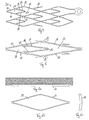
- the holding elements 14 are each formed from at least two second webs 15, 16, which are on the one hand connected to each other and having a tip 17. The tip 17 projects into the cell 13 of the lattice structure, as in FIG Fig. 2 to recognize.
- the second webs 15, 16 are connected to the first webs 11 of the cell 13. This results in a web-shaped holding element having a V-shaped profile, the tip 17 of the V-shaped profile facing in the distal direction.
- the two webs 15, 16 diverge from the tip 17 and are at the end in about as wide as the width of the cell 13 spanning webs 11 in the region of the junction. Another number of second webs 15, 16 is possible.
- the first webs 11 of the lattice structure 12, which are connected to the second webs 15, 16 of the holding element 14, also have a V-shape, which is arranged in the opposite direction to the V-shape of the holding element 14.
- the second webs 15, 16 of the holding element 14 together with the first webs of a cell 13 of the grid structure 12, a further cell 18.
- the smaller cell 18 is disposed in the larger cell 13 of the lattice structure 12, wherein the smaller cell 18 partially through the second webs 15, 16 of the holding element and partially by web portions 11 of the grid structure is limited.
- the shape of the further cell 18, ie the smaller cell 18, corresponds to the shape of the cell 13 of the lattice structure 12 in which the further cell 18 is arranged. In the example according to Fig. 2 in both cases it is a rhombic cell. Other cell geometries are possible.
- the two second webs 15, 16 of the holding element 14 engage approximately centrally on the first webs 11 of the cell 13. It is also possible to connect the second webs 15, 16 of the holding element 14 with the first webs 11 of the cell 13 at a different, off-center location, for example closer to the top of the cell 13 of the grid structure 12 or closer to the connectors 19. Das means that the second webs 15, 16 of the holding element 14 each engage a position of the associated first webs 11 of the grid structure 12, which is located between two connectors 19, the respective first web 11th axially limit.
- the term "axial" refers in this context to the longitudinal extent of the individual web.
- the holding member 14 is thus a separate element which is provided in addition to the connectors 19.
- the tip 17 of the holding element 14 is arranged at least at the level of the lateral connectors 19. In the embodiment according to Fig. 2 the tip 17 protrudes beyond an imaginary connecting line between the two connectors 19 of a cell. It is also possible to position the tip 17 behind the imaginary line between the two circumferentially opposed connectors 19. The tip 17 is rounded in order to effect the atraumatic anchoring of the implant.
- the stent design according to Fig. 2 it is an axisymmetric design, based on the individual cells, in which the other cells 18, which are formed from the webs 15, 16 of the holding elements 14, and the cells of the grid structure 12 are in line.
- the longitudinal axis L 'of the further cell 18 is aligned with the longitudinal axis L "of the respectively associated cell 13 of the lattice structure 12.
- the tips of the individual holding elements 14 each face in the distal direction, thereby facilitating the retraction of the stent into the catheter.
- two edge regions 20, 21 are provided, in which the closed cells have 13 holding elements 14.
- the intermediate region 22 arranged between the two edge regions 20, 21 is formed of cells 13 without holding elements 14.
- the holding elements 14 are arranged so that the central region of the stent does not lose its pore size and the permeability of the cells in the central region is not impaired.
- the anchoring function is thus limited to the edge areas.
- Another arrangement of the functionally different areas of the stent is possible. Specifically, the closed cells 13 with the holding elements 14 ring segments 23 which are arranged downstream of each other in the axial direction.
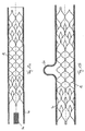
- the individual ring segments 23 are composed of circumferentially arranged closed cells, which are each connected by lateral Ver-binder 19. As in Fig. 1 To recognize, the number of proximal ring segments 23 is greater than the number of distally disposed ring segments 23, whereby a precise Positioning of the stent during release associated with a relatively easy recoverability is achieved. In the embodiment according to Fig. 1 2 ring segments 23 are provided on the proximal stent side and 3 ring segments 23 on the distal stent side. Another number of ring segments 23 with holding elements 14 is possible both proximally and distally. It is also possible to provide the same number of ring segments 23 with retaining elements 14 both proximally and distally.
- the two edge regions 20, 21 are each connected to markers, in particular to x-ray markers 24.
- the closed cells 13 of the lattice structure 12 have a diamond-shaped or diamond-like geometry, wherein the individual legs of the diamond geometry are formed by the webs 11 of the lattice structure.
- the shape angle of the single cell 13, i. the angle between the longitudinal axis of the cell and the connecting line between a lateral and a tip-forming connector 19 is preferably 50 °.
- the forming angle can be ⁇ 25 °, ⁇ 30 °, ⁇ 35 °, ⁇ 40 °.
- the upper limit of the forming angle can be ⁇ 60 °, ⁇ 55 °, ⁇ 50 °, ⁇ 45 °.
- the values of the angle of molding given above refer to the rest state.
- Fig. 5 is a partially deformed cell 13 with holding element 14, which is deformed according to the cell 13 shown.
- a pure closed cell design ie a closed cell 13 without holding member 14 to the fact that the vessel wall is stretched relatively strong with the result that the webs 11 of the closed cell 13 press weaker into the vessel wall.
- the holding member 14 more in the vessel wall which protrudes in the implanted state via the wall of the stent or generally of the implant partially radially outward. By the rounded atraumatic tip 17 injuries to the vessel wall are avoided.
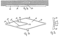
- the outwardly directed radial deflection of the holding element 14 in the expanded state is also in Fig. 9c shown.
- the holding element 14 it is also possible to form the holding element 14 such that the tip 17 in the expanded state does not protrude beyond the wall 10, but remains in the plane between the webs 11, as in FIG Fig. 7a, 7b and 7c shown.
- the radial deflection of the retaining element 14 is adjusted by the ratio of the web width to the wall thickness of the webs 11. This makes it possible to influence the position of the tip 17 in the expanded state such that it either remains in the wall 10 or projects outwardly beyond the wall 10.
- the holding element 14 In the event that the holding element 14 is not deflected radially and the tip 17 remains in the wall plane, the holding element 14 has a holding function.
- the holding function of the holding element 14 results in this case from the fact that the webs 11 and the holding element 14 press into the intima of the vessel wall, resulting in a corresponding resistance effect.
- the anchoring of the stent by means of the holding elements 14 is particularly pronounced when the stent is in curvature, as in Fig. 8a, 8b, 8c shown.
- the holding elements 14 are moved even more out of the wall plane and emboss deeper into the vessel wall. This further reduces the risk of dislocation of the stent in the distal direction.
- a further embodiment of the stent according to the invention is shown in plan view Fig. 10 shown.
- a circumferential segment of the stent is shown in the unfolded state, wherein the illustrated circumferential segment comprises a part of the intermediate region 22 and a peripheral portion of the edge region 20.
- the intermediate region 22 is formed of closed cells 13, which are each coupled to four connectors 19 with adjacent cells 13 in both the axial and circumferential directions.
- the closed cells 13 are substantially diamond-shaped.
- closed cells 13 are arranged in the edge region 20, which are equipped with retaining elements 14.
- the holding elements 14 are clamped between two first webs 11 of the lattice structure 12.
- the holding elements 14 and the second webs 15, 16 of the holding elements 14 are respectively coupled to axial ends 24 of the first webs 11.
- the axial end 24 of a first web 11 forms the boundary of the web 11 in the axial direction with respect to the longitudinal extension of the individual web 11 and passes directly into the connector 19.
- the holding element 14, in particular the second webs 15, 16 with the tip 17 forms a V-shaped profile, which extends into the closed cell 13.
- the first webs 11, which are coupled to the retaining element 14 are shortened. In general, therefore, the first webs 11 coupled to the holding element 14 have a different axial length than the first webs 11 coupled directly or directly via connectors 19. It is also possible for the first webs 11 connected to the holding element 14 to have the same length like the free first webs 11.
- the first webs 11 are articulated substantially on the second webs 15, 16, the retaining element 14 extending between the first webs 11 such that the retaining element 14 substantially replaces a connector 19 of the cell 13.
- the second webs 15, 16 are extended in the longitudinal direction of the stent and each form a web extension 15a, 16a.
- the web extensions 15a, 16a converge and are combined to form a common further tip 17a.
- the holding element 14 is thus formed symmetrically, wherein the axis of symmetry is defined by the axial ends 24 of the first webs 11.
- the shape of the holding element 14 can be described as a leaf spring-like or lenticular.
- the second webs 15, 16 thus form with the respective web extension 15a, 16a each a circular arc segment, wherein the circular arc segments are coupled to each other at the two longitudinal ends with respect to the stent longitudinal axis and form the tip 17 and the further tip 17a.
- the holding element 14 is displaced in the direction of the closer stent end relative to the closed cell 13, so that the Connection point between the first webs 11 and the second webs 15, 16 coincides with the position of the connector 19 which limits the closed cell 13 in the longitudinal direction of the stent.
- the closed cell 13 or the basic cell can be considered to be formed by the first webs 11 and the web extensions 15a, 16a.
- the holding element 14 is formed only from the second webs 15, 16, which are brought together to form a tip 17.
- the first webs 11 are not aligned with the web extension 15a, 16a. Rather, the web extensions 15a, 16a, which are considered in this view as part of the first webs 11, aligned with the second webs 15, 16 in alignment.
- the first webs 11 at the point of connection to the holding element 14 each form a bend or a curvature which forms the transition between the first webs 11 and the web extension 15a, 16a.
- the shape of the first webs 11 in the intermediate region differs from the shape of the first webs 11 in the edge region.
- the first webs 11 are substantially rectilinear.
- the connectors 19 are coupled in the intermediate region 22 by substantially rectilinear or straight first webs 11.
- the first webs 11 thus extend between the connectors 19 in the intermediate region 22 at least in the circumferential plane of the stent without bending.
- the first webs 11 in the edge region have a curvature in the vicinity of the connectors 19, which limit the cell 13 in the longitudinal direction, and / or form a thickening in the region of the connector 19.
- first webs 11 are aligned with each other in a V-shape, wherein the V-shaped tip ends in the region of the connector 19 and the angle between the first webs 11 varies, in particular with a greater distance from the connector 19 is widened. It has generally been shown that in particular with the structure of the stent according to the Embodiment after Fig. 10 a stress or voltage optimized function is achievable.
- the embodiments illustrated in the figures are based on a substantially diamond-shaped cell geometry in which specially shaped, in particular web-shaped holding elements 14 are arranged in the edge regions of the stent, that the anchoring of the stent improves and slipping of the stent is avoided during the intervention.
- the arrangement of the retaining elements 14 in the edge regions of the stent also ensures that in the middle region of the stent, i. in the area between the edge areas, the pore size is maintained, so that the permeability of the cells is not affected in this area.
- Disposing the tips 17 of the retaining members distally results in a barb effect, while allowing retraction of the retaining members 14 into a catheter of the up to 80% deflated stent. This is not possible with stents made on the basis of an open cell design.
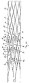
- Fig. 11 shows a stent according to an embodiment of the invention in the developed state.
- the stent according to Fig. 11 corresponds essentially to the stent according to Fig. 1 However, wherein the first webs 11 have an S-shaped profile.
- the stent according to Fig. 11 comprises two edge regions 20, 21, which are provided with X-ray markers 25.
- the edge regions 20, 21 each form the axial ends 24 of the stent.
- a row of circumferentially adjacent closed cells 13 is provided at the axial ends 24 of the stent, with each second closed cell carrying an x-ray marker 25.
- each ring segments 23 close.
- three rows in the circumferential direction of adjacent closed cells 13 are provided, each forming a ring segment 23.
- the ring segments 23 differ from the other segments of the stent in that the closed cells 13 in the ring segments 23 each comprise a holding element 14.
- Between the ring segments 23 extends an intermediate region 22, which comprises one or more rows in the circumferential direction of adjacent closed cells 13.
- the closed cells 13 of the intermediate region 22 are free of holding elements. In other words, the closed cells 13 of the intermediate region 22 have no holding elements 14.
- the tips 17 of the holding elements 14 in the ring segments 23 each in the same direction. It is particularly preferred if the tips 17 of all holding elements 14 of the ring segments 23 or generally of the stent point in the same direction, in particular in the distal direction relative to a feed system.
- Fig. 11 indicates the distal direction according to the drawing to the right, whereas the proximal direction points to the left.
- the closed cells 13 of the edge region 21 in the right-hand drawing section form the distal end of the stent
- the closed cells 13 of the edge region 20 in the left-hand half of the drawing form the proximal end of the stent.
- the closed cells 13 of the edge regions 20, 21, the ring segments 23 and the intermediate region 22 are formed such that the stent over the entire length has a constant, in particular uniform, radial force.
- the shape and / or the size of the individual closed cells 13 in the respective segments or regions of the lattice structure 12 are designed such that the normalized radial force, ie the radial force per stent length, or the radial pressure over the entire length or the Scope of the stent remains substantially constant.
- the closed cells 13, which comprise holding elements 14 are formed larger than closed cells 13, which do not comprise holding elements 14, in order to compensate for the increased radial force by the holding elements 14.
- the closed cells 13 with retaining elements 14 in the edge regions 20, 21 of the lattice structure 12 may comprise a different radial force than the closed cells 13 of a middle region, in particular the ring segments 23, the lattice structure 12, which have no holding elements 14.
- the radial force can be influenced by the geometry of the cell 13. For example, the length of the cell 13 - viewed along the longitudinal axis of the grid structure - or the angle of the first webs 11 of a cell 13 can be varied in order to adjust the radial forces in different sections of the grid structure 12.
- the radial force in the edge regions 20, 21 may be smaller or larger than the radial force in a central region of the lattice structure 12.
- the cells 13 in the edge regions 20, 21 are geometrically dimensioned in such a way that they have the same radial force as the cells 13 of a middle region of the lattice structure 12.
- the radial force along the lattice structure 12 may be constant.
- the adjustment of the radial forces along the lattice structure 12 is dependent on the application of the medical device and is chosen according to the expert. It can be considered that a radial force in the edge regions 20, 21 of the lattice structure 12, the cells 12 in the edge regions 20, 21 holding elements 14, the risk of side effects, such as the risk of stenosis, in the edge region 20, 21 of the implanted medical device reduced.
- the deformation force of the respective associated cell 13 is increased by the holding elements 14.
- the holding elements 14 With a radial compression of the stent or the lattice structure 12 with respect to the resting state, not only the first webs 11 of the cell deform, but also the second webs 15, 16 of the holding element.
- the radial force increases due to the presence of a holding element 14, even if the cell 13 has the same geometric dimensions.
- the cells 13 in an edge region 20, 21 of the lattice structure 12 may comprise anchoring cells 13a, ie cells 13 holding elements 14, which have the same profile and dimensional proportions (ridge width, ridge length, cell angle, cell width, the holding element-free cells 13, so the free cells 13 b, in a central region (without holding element) have.
- the radial force in the edge region 20, 21 by the additional holding elements 14 is greater than in the central region.
- the radial force in the edge region 20, 21 of the lattice structure 12 is reduced or equalized to the radial force in the middle region of the lattice structure 12.
- the mechanical properties, in particular the radial force, of the edge regions 20, 21 and the middle region can be identical.
- An abrupt transition characterized by very different forces can lead to a high local load on the vessel in the transition region, since the pulsatility wave or wave of deformation of the vessel, which is caused by the pulsating blood flow, can change greatly on both sides of the transition region.
- the cells 13 in the edge region 20, 21 have a different or different geometric shape than the cells 13 in the central region. This has the effect that a cell 13 arranged in the edge region 20, 21 per se, ie without consideration of the holding element, causes a smaller radial force than a cell 13 in the middle region of the lattice structure 12. This will u.a. achieved by a smaller tip angle, ie the angle between two first webs in the region of a connector, and / or by a smaller web width and / or by longer webs and / or by a smaller number of cells 13 in a circumferential row and / or by different web geometries, in particular different radii of curvature of the first webs.
- the angle of the first webs 11 of the cells 13 in a middle region of the lattice structure 12 can preferably be at most 15 °, in particular at most 10 °, in particular at most 5 °, smaller than the angle of the first webs 11 of the cells 13 in an edge region 20, 21 of the grid structure 12 may be.
- the effect of the radial force increase is counteracted by the holding elements 14.
- the radial force in an edge region 20, 21 may be adjusted or set to the same value in a central region by the change of the geometry to the mechanical properties, in particular the radial force.
- the radial force in an edge region 20, 21 may be adjusted or set to the same value in a central region by the change of the geometry to the mechanical properties, in particular the radial force.
- only one or more first circumferential rows or one or more first circumferential segments of the grid structure 12 comprising anchoring cells 13a and connected to free cells 13b of a central region may have the same radial force as the circumferential rows of a central region of the grid structure 12.
- the radial force may gradually increase.
- peripheral rows or peripheral segments arranged in an edge region 20, 21, which have cells 13 with holding elements (anchoring cells 13a), or at least some of these circumferential segments with anchoring cells 13a have a lower radial force than working segments in a middle region of the grid structure 12 which do not comprise holding elements 14 or are formed by free cells 13b.
- anchoring cells 13a holding elements
- free cells 13b free cells
- the radial force in the edge region 20, 21 of the lattice structure 12 can be lowered stepwise and / or gradually in the direction of the axial end of the lattice structure 12 in order to preserve the vessel walls in the implanted state at least in the sections in which the edge region 20, 21 of FIG Grid structure 12 is arranged.
- a combination of cells 13 and peripheral segments of the peripheral regions 20, 21 with lower, equal or higher radial force compared to the cells 13 of a central region of the lattice structure 12 is possible.
- the reduction of the radial force in the circumferential segments, which comprise cells 13 with holding elements, is possible with respect to the adhesion of the stent or lattice structure 12 to a vessel wall, since the holding elements 14 allow a "geometric locking" Locking is effected at least mainly by the geometric shape of the holding elements 14.
- the shape of the holding elements 14 allows good adhesion even with a comparatively low radial force of the associated cells.
- Conventional radial force measuring systems can be used to measure the radial force, which have a plurality of fins which close inwards in the manner of a blind. It is also possible to examine separate cells 13. The separate cells 13 can be stretched on a tractor. From the value of the deformation force, the value of the radial force of the stent can be extrapolated.
- the grid structure 12 rows S HE closed cells 13 with holding elements 14 and rows S closed cells 13 without holding elements 14.
- two, three, four, five, six, seven, eight, or nine are in the axial end portions of the stent or lattice structure 12, respectively Rows S HE closed cells 13 provided with retaining elements 14.
- the ratio between rows S HE closed cells 13 with holding elements 14 to rows S closed cells 13 without holding elements 14 (S HE / S), a range of 2/4 to 2/10, in particular 3/3 to 3/12, in particular 4/4 to 4/10, in particular 5/5 to 5/15, in particular 6/4 to 6/16, in particular 7/5 to 7/24, in particular 8/4 to 8/20, in particular 9/5 to 9 / 27, in particular 10/4 to 10/30, in particular 12/4 to 12/32.
- the closed cells 13, which comprise a holding element 14, are referred to below as anchoring cells 13a. Closed cells 13 that do not include holding elements 14 are called free cells 13b. Furthermore, a distinction is made between transition cells 13c, which are each arranged between a row of anchoring cells 13a and a row of free cells 13b and effect the transition between the different dimensions of the anchoring cells 13a and the free cells 13b.
- the transitional cells 13c may have holding elements 14.
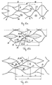
- a connector distance L4 is determined, which corresponds to the distance between two connectors 19, which are coupled by a common first web 11.
- the connector distance L4 thus substantially extends obliquely to the longitudinal axis or to the longitudinal direction of the lattice structure 12th FIG. 12b
- a tip distance L5 can be derived, which corresponds to the distance of the tip 17 of the holding element 14 from a starting point 26.
- the tip 17 and the attachment point 26 each form one end of the second web 15, 16 of the retaining element 14.
- the approach point 26 thus corresponds to the point at which the second web 15, 16 of the retaining element 14 the first web 11 of the closed cell 13 springs.
- an approach distance L6 is provided, which corresponds essentially to the distance between a starting point 26 and a connector 19, wherein the connector 19 is associated with the further cell 18, which also includes the attachment point 26.
- the further cell 18 is formed by two web attachment sections 11a of two first webs 11, which are coupled in the connector 19, and the second webs 15, 16 of the retaining element 14.
- the holding element 14 together with one web attachment section 11a of two first webs 11 forms the further cell 18, which protrudes into the closed cell 13.
- the attachment point 26 has a residual web distance L7 to a further connector 19, which is connected to the attachment point 26 by a residual web portion 11b.
- the residual web distance L7 therefore essentially corresponds to the distance between the attachment point 26 and a connector 19, the distance being measured along the residual web portion 11b.
- the first webs 11, from which the second webs 15, 16 of the retaining element 14 spring, are divided into two sections, namely the web attachment section 11a and the residual web section 11b.
- the web attachment section 11 a is part of the further cells 18 which is formed by the retaining element 14.
- the residual web section 11b is associated with the closed cell 13.
- the distance between the tip 17 of the retaining element 14 and a connector 19 associated with the further cell 18 formed by the retaining element 14 corresponds to the retaining element length L8, as in FIG Fig. 12c shown.
- the length of the further cells 18 in the axial direction or in the longitudinal direction of the lattice structure 12 is referred to as holding element length L8.
- the tip 17 of the holding member 14 is additionally aligned with another connector 19 of the closed cell 13.
- the distance between the tip 17 and another connector 19 which is aligned in the longitudinal direction of the grid structure 12 with the tip 17 and not the holding element 14, the the tip 17 is assigned, is referred to as opening length L9.
- the opening length L9 corresponds to the difference between the anchoring cell length L1 and the holding element length L8.
- the aforementioned lengths or distances L4-L9 with the exception of anchoring cell length L1, the free cell length L2 and the transition cell length L3 can basically refer to the dimensions of all closed cells 13.
- the length or distance indications are therefore not restricted to a particular shape of the cell, that is not to an anchoring cell 13, a free cell 13b or a transition cell 13c.
- the distances L4-L7 is basically a straight-line connection, shown in the figures as a dashed line, based.
- all lengths and distances refer to the fully expanded state of the lattice structure 12, ie the manufacturing state.
- the ratio between the transition cell length L3 and the free cell length L2 is preferably at least 0.6, in particular at least 0.7, in particular at least 0.8, in particular at least 0.9.
- the upper limit for the ratio between the transition cell length L3 and the free cell length L2 (L3 / L2) is preferably a value of at most 2.5, in particular at most 2.3, in particular at most 2.1, in particular at most 2, in particular at most 1.8, in particular at most 1.6, in particular at most 1.5 provided.
- the ratio between the anchoring cell length L1 and the connector spacing L4 is preferably a value of at least 1, in particular at least 1.2, in particular at least 1.4, in particular at least 1.5.
- the ratio between Anchoring cell length L1 and connector spacing L4 (L1 / L4) at most 3, in particular at most 2.8, in particular at most 2.6, in particular at most 2.4.
- the transition cell length L3 may have a ratio (L3 / L4) to the connector spacing L4 which is at least 0.9, in particular at least 1, in particular at least 1.1, in particular at least 1.2.
- the ratio between the transition cell length L3 and the connector spacing L4 (L3 / L4) comprises at most 2.5, in particular at most 2.4, in particular at most 2.3, in particular at most 2.2, in particular at most 2.1, in particular at most 2, 0th
- a lower limit for the ratio between the connector distance L4 and the tip distance L5 (L4 / L5) is preferably at least 0.8, more preferably at least 0.9, especially at least 1, more preferably at least 1.0.
- the maximum value for the ratio between the connector distance L4 and the peak distance L5 (L4 / L5) is preferably at most 2.5, in particular at most 2.4, in particular at most 2.3, in particular at most 2.2, in particular at most 2.1 in particular at most 2.
- the ratio between the approach distance L6 and the residual web distance L7 is preferably at least 0.2, in particular at least 0.3, in particular at least 0.4, in particular at least 0.5.
- For the ratio between approach distance L6 and residual land distance L7 (L6 / L7) is preferably a maximum value of at most 2, in particular at most 1.8, in particular at most 1.6, in particular at most 1.4, in particular at most 1.2, in particular at most 1, in particular at most 0.8, in particular at most 0.6.
- the holding element length L8 preferably relates to the anchoring cell length L1 in a ratio (L8 / L1) of at least 0.2.
- the ratio between holding element length L8 and anchoring cell length L1 (L8 / L1) is preferably at most 1.0, in particular at most 0.75, in particular at most 0.7, in particular at most 0.65, in particular at most 0.6.
- the abovementioned maximum values preferably also apply to the ratio between the opening length L9 and the anchoring cell length L1.
- the ratio between the opening length L9 and the anchoring cell length L1 (L9 / L1) is preferably at most 1.0, more preferably at most 0.75, in particular at most 0.7, in particular at most 0.65, in particular at most 0.6.
- the lower limit of the ratio between the opening length L9 and the anchoring cell length L1 (L9 / L1) is preferably at least 0.2.
- the holding element length L8 and the opening length L9 are preferably in a ratio (L8 / L9) to one another that is at least 0.6, in particular at least 0.7, in particular at least 0.8, in particular at least 0.9, in particular at least 1.
- the upper limit for the ratio between holding element length L8 and opening length L9 (L8 / L9) is preferably at most 2, 5, in particular at most 2.2, in particular at most 2.0, in particular at most 1.8, in particular at most 1.6, in particular at most 1 ; 5.
- the connector distance L4, the tip distance L5, the approach distance L6, the residual land distance L7, the holding element length L8 and the opening length L9 can each be based on different configurations of the closed cells 13, in particular both the anchoring cell 13a, and the free cell 13b, as well Transition cell 13c, relate.
- Fig. 13a shows the stent according to Fig. 11 in the implanted state within a hollow body organ 40.
- the stent or the lattice structure 12 is expanded in the hollow body member 40 and abuts the vessel walls of the hollow body organ 40 at.
- Fig. 13 5 illustrates the tip of a delivery system 30 with which the stent has been inserted into the body hollow organ 40.
- all holding elements 14 of the lattice structure 12 or their tips 17 in the distal direction, ie away from the feed system 30, have. This makes it possible to return the stent or the lattice structure 12 to the delivery system 30, in particular if the lattice structure 12 is only partially released from the delivery system 30.
- a hooking of the holding elements 14 during retraction is prevented in the feed system 30.
- the anchoring of the medical device or the lattice structure 12 in a hollow body organ 40, in particular a blood vessel, is predominantly due to the geometric conditions in the cells 13, the holding elements 14 have.
- the first and second webs 11, 15, the length of the cells 13 and the wall thickness and web widths the improved anchoring in the blood vessel or general body cavity 40 reached.
- the degree of radial deflection of the holding elements 14 can be influenced by suitable geometric design.
- the holding elements 14 may be constructed such that a deflection takes place only by a curvature of the grid structure 12 along a longitudinal axis.
- the alignment of the holding elements 14, in particular of all the holding elements 14 in the distal direction enables an improved anchoring of the grid structure 12 or of the implant in the body cavity 40. This advantage is particularly effective when using the stent or the grid structure 12 as a coil stick.
- Coilstents serve to cover an aneurysm 50, as in Fig. 13b shown.
- the coil catheter hooks into the lattice structure 12 and the lattice structure 12 is displaced by an axial movement of the coil catheter in the hollow body member 40.
- an additional anchoring of the lattice structure 12 in the vessel wall of the hollow body organ 40 is achieved by the holding elements 14, so that the risk of a displacement or dislocation of the lattice structure 12 is lowered or minimized.
- the grid structure 12 according to Fig.
- FIG. 11 in use as a coil catheter in Fig. 13b is particularly suitable for covering aneurysms 50, since the holding elements 14 are arranged in the region of the axial end portions of the lattice structure 12, which can be positioned outside of the aneurysm 50, preferably in the healthy regions of the hollow body organ 40.
- the radial force of the lattice structure 12 causes the webs 11 of the lattice structure 12 to at least partially press into the vessel wall of the hollow body organ 40.
- the radial force which acts on the hollow body member 40 starting from the lattice structure 12, results in a kind of undercut, as in FIG Fig. 14a shown.
- the webs 11 of the lattice structure 12 are at least partially enclosed by the vessel wall of the hollow body member 40.
- anchoring of the lattice structure 12 in the vessel wall of the hollow body member 40 is effected.
- the aforementioned undercut counteracts an axial dislocation of the stent. This effect is enhanced with closed cells 13 comprising a support member 14, as in FIG Fig.
- FIG. 15a the anchoring of a closed cell 13 with a holding element 14 in a vessel wall of a hollow body organ 40 is shown. This results in an indentation depth E3, which represents the amount by which the closed cell 13 sinks or is pressed into the vessel wall.
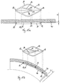
- an arrangement of the closed cell 13 according to Fig. 15a in a vessel curvature as in Fig. 15b shown, there is a penetration depth E2 of the holding member 14, which increases starting from the starting point 26 to the tip 17 and is greater than the penetration depth E1 of the first webs 11.
- the holding element 14 is thus deflected in an arrangement in a vessel curvature relative to the first webs 11 and the closed cell 13 radially outward.
- the anchoring of the lattice structure 12 in a vessel curvature is improved.
- the first webs 11 of the closed cell 13 and the second webs 15, 16 of the retaining element 14 preferably have different web widths.
- a ratio between the web width S1 of the first webs 11 and the web width S2 of the second webs 15, 16 (S1 / S2) is preferably provided, which is at least 0.5 and at most 2.
- the web width S1 of the first webs 11 and / or the web width S2 of the second webs 15, 16 preferably comprises a value of at least 0.010 mm, in particular at least 0.015 mm, in particular at least 0.020 mm, in particular at least 0.025 mm.
- the web width S1 of the first webs 11 and / or the web width S2 of the second webs 15, 16 may be at most 0.06 mm, in particular at most 0.08 mm, in particular at most 0.07 mm, in particular at most 0.06 mm.
- the wall 10 of the implant preferably has a wall thickness W which is at least 0.03 mm, in particular at least 0.04 mm, in particular at least 0.05 mm and / or at most 0.09 mm, in particular at most 0.08 mm, in particular at most 0.07 mm, in particular at most 0.06 mm, in particular at most 0.055 mm.
- a ratio between the wall thickness W and the web width S1 of the first webs 11 or web width S2 of the second webs 15, 16 (W / S1 or W / S2), which is at least 0.8, in particular at least 0.9, in particular at least 1, in particular at least 1.1, in particular at least 1.2, in particular at least 1.3, and / or at most 2.0, in particular at most 1.8, in particular at most 1.6, in particular at most 1.4.
- the cross-sectional diameter of the implant or the lattice structure 12 in the expanded state or production state is preferably at least 1.5 mm, in particular at least 1.75 mm, in particular at least 2.0 mm, in particular at least 2.25 mm, in particular at least 2.5 mm ,
- the upper limit for the expanded diameter D of the implant or the lattice structure 12 is a value of at most 6.5 mm, in particular at most 5.5 mm, in particular at most 5.0 mm, in particular at most 4.5 mm, in particular at most 4.0 mm, in particular at most 3.5 mm, in particular at most 3.0 mm provided.
- a preferred insertion diameter is specified which corresponds to the preferred diameter in the implanted state and is preferably at least 1.0 mm, in particular at least 1.5 mm, in particular at least 2.0 mm.
- the preferred insert diameter may be at most 6.0 mm, in particular at most 5.5 mm, in particular at most 4.5 mm, in particular at most 4.0 mm, in particular at most 3.5 mm, in particular at most 2.5 mm.
- the stent length is preferably at least 10 mm, in particular at least 12 mm, in particular at least 14 mm, in particular at least 15 mm.
- a maximum length of the stent or a maximum stent length is preferably at most 150 mm, in particular at most 140 mm, in particular at most 130 mm, in particular at most 120 mm, in particular at most 100 mm, in particular at most 80 mm, in particular at most 60 mm, in particular at most 40 mm, in particular at most 20 mm.
Landscapes
- Health & Medical Sciences (AREA)
- Engineering & Computer Science (AREA)
- Biomedical Technology (AREA)
- Cardiology (AREA)
- Oral & Maxillofacial Surgery (AREA)
- Transplantation (AREA)
- Heart & Thoracic Surgery (AREA)
- Vascular Medicine (AREA)
- Life Sciences & Earth Sciences (AREA)
- Animal Behavior & Ethology (AREA)
- General Health & Medical Sciences (AREA)
- Public Health (AREA)
- Veterinary Medicine (AREA)
- Physics & Mathematics (AREA)
- Optics & Photonics (AREA)
- Prostheses (AREA)
Description
- Die Erfindung betrifft ein medizinisches Implantat mit einer Wandung, die eine von einem komprimierten in einen expandierten Zustand überführbare und aus ersten Stegen gebildete Gitterstruktur umfasst, wobei die Gitterstruktur geschlossene Zellen mit jeweils einem Halteelement aufweist, das zur Verankerung der expandierten Gitterstruktur in einem Gefäß angepasst ist. Ein derartiges Implantat ist beispielsweise aus
US 5,397,355 bekannt. - Im Bereich der interventionellen Neuroradiologie haben sich zwei grundsätzliche Stentdesigns zur Behandlung von Aneurysmen und Gefäßstenosen bewährt und zwar sogenannte Closed Cell Designs oder Open Cell Designs. In jüngere Zeit wurden verstärkt Closed Cell Designs eingesetzt, die den Vorteil haben, dass ein Stentsystem nach bereits erfolgter teilweiser Entlassung im Zielgebiet wieder in den Katheter eingezogen werden kann. Die auf dem Markt verfügbaren Stentsysteme, die in Kombination mit sogenannten Coils für die Therapie von Aneurysmen eingesetzt werden, können jedoch Schwächen in der Applikationssicherheit aufweisen. Nach dem Entlassen des Stentsystems wird ein Coilkatheter durch die Zellen des Stents in das Aneurysma eingeführt, um das Coil in das Aneurysma zu bringen. Dabei kann sich der Coilkatheter in den Spitzen der Zellen verhaken, so dass - bei unzureichender Verankerung des Stents im Blutgefäß - der Stent verrutschen kann. Eine unzureichende Verankerung des Stents im Blutgefäß kann beispielsweise durch eine zu geringe nach außen gerichtete Radialkraft oder durch die Ausprägung der Zellgeometrie bedingt sein. Zudem sind häufig Schwächen bei der Anpassung an die anatomischen Verhältnisse im neurocerebralen Gefäßsystem bei bekannten Stentsystemen zu beobachten.
- Ein Stent mit einem Open Cell Design ist beispielsweise in
US 2005/0143801 A1 beschrieben. Dabei weist der Stent Hakenelemente auf, die dazu dienen, eine Abdeckung auf dem Stent zu fixieren (Stent-Graft). Ein Zurückziehen des Stens in einen Katheter, beispielsweise um eine Fehlpositionierung zu korrigieren, ist nicht möglich, da sich die Hakenelemente beim Zurückziehen des Stents an der Katheterspitze verhaken. - Der Stent gemäß
US 5,397,355 weist eine aus Stegen gebildete Gitterstruktur auf, die von einem komprimierten in einen expandierten Zustand überführt werden kann. Die Gitterstruktur ist aus geschlossenen Zellen gebildet (Closed Cell Design). Zur Verankerung der expandierten Gitterstruktur in einem Gefäß weisen die Zellen jeweils ein Halteelement auf, das im expandierten Zustand radial nach außen bewegt ist und über die Wandung des Stents hinausragt. Das Halteelement ist als Dorn mit einer scharfen Spitze ausgebildet, die sich im implantierten Zustand in die Gefäßwand bohrt. Dabei kann es zu Verletzungen kommen. - Eine weitere Möglichkeit, einen Stent im Gefäß zu verankern, ist in
US 5,330,500 offenbart, die, ähnlich wie der vorstehend beschriebene bekannte Stent hakenförmige Spitzen in den Zellen aufweist, die sich im implantierten Zustand in die Gefäßwand bohren.US 5,800,526 beschreibt einen Stent mit einem Verankerungssystem, bei dem die Gitterstruktur so ausgebildet ist, dass diese abschnittsweise im implantierten Zustand über die Wandung des Stents vorsteht und den Stent gegen Dislokation fixiert. Bei dem Stent handelt es sich aber nicht um ein Closed Cell Design, sondern um ein Open Cell Design, das den Nachteil hat, dass dieses nur schlecht nach dem Entlassen in den Katheter zurückgezogen werden kann. Dasselbe gilt für den Stent gemäßUS 2006/0100695 A1 , der eine Gitterstruktur aufweist, die teilweise aus geschlossenen und teilweise aus offenen Zellen gebildet ist. Der Stent hat eine arzneimittelabgebende Funktion (drug eluting stent) und weist hierfür eine besonders große Oberfläche auf. Dazu sind verschiedene Möglichkeiten offenbart, unter anderem die Möglichkeit, die Stege eines offenzelligen Stentabschnittes durch Zwischenstege zu verbinden. Diese Zwischenstege haben nicht die Funktion eines Halteelements, sondern sollen ausschließlich die wirksame Stentoberfläche vergrößern. -
WO 2008/125145 A1 offenbart einen Stent mit einer Gitterstruktur, die stellenweise unterbrochen ist. In den Unterbrechungen sind Halteelemente in Form von Fortsätzen oder V-förmig angeordneten Stegpaaren angeordnet. Diese Fortsätze bzw. Stegpaare sind jeweils mit Verbindern der Gitterstruktur gekoppelt. Die Verbinder bilden im Wesentlichen Gelenkstellen, so dass die Halteelemente unter Krafteinwirkung leicht ausweichen. Das birgt das Risiko, dass die Halteelemente im implantierten Zustand in den Blutfluss hineinragen und unerwünschte Verwirbelungen hervorrufen. - Der Erfindung liegt die Aufgabe zugrunde, ein medizinisches Implantat anzugeben, das eine Gitterstruktur mit geschlossenen Zellen aufweist und im Hinblick auf die Applikationssicherheit verbessert ist.
- Erfindungsgemäß wird diese Aufgabe durch ein medizinisches Implantat mit den Merkmalen des Anspruchs 1 gelöst.
- Die Erfindung beruht auf dem Gedanken, ein medizinisches Implantat mit einer Wandung anzugeben, die eine von einem komprimierten in einen expandierten Zustand überführbare und aus ersten Stegen gebildete Gitterstruktur umfasst, wobei die Gitterstruktur geschlossene Zellen mit jeweils einem Halteelement aufweist. Das Halteelement ist zur Verankerung der expandierten Gitterstruktur in einem Gefäß angepasst. Das Halteelement weist wenigstens zwei zweite Stege auf, die einerseits miteinander verbunden sind und eine Spitze bilden, die in die Zelle ragt. Andererseits sind die zweiten Stege des Halteelements mit den ersten Stegen der Zelle verbunden.
- Die Erfindung hat mehrere Vorteile. Die Ausbildung des Halteelements mit wenigstens zwei Stegen bietet die Möglichkeit, eine atraumatische Ausgestaltung des Halteelements zu verwirklichen im Gegensatz zu dem Halteelement gemäß
US 5,397,355 . Überdies führt die stegförmige Ausbildung des Halteelements dazu, dass auf dem Umfang des Implantats die Anzahl der Stege und somit die auf die Gefäßwand wirkende Radialkraft erhöht wird. Dadurch ergibt sich der Vorteil, dass die Applikationssicherheit verbessert wird, insbesondere im Hinblick auf eine Vermeidung der Dislokation des Stents, ohne dass dabei der Hauptvorteil von Closed Cell Stentsystemen beeinträchtigt wird, nämlich die Möglichkeit, das Stentsystem nach erfolgter Teilentlassung im Zielgebiet wieder in den Katheter einzuziehen. - Bei einer bevorzugten Ausführungsform der Erfindung bilden die zweiten Stege des Halteelements mit den ersten Stegen einer Zelle der Gitterstruktur eine weitere Zelle, die in der Zelle der Gitterstruktur angeordnet ist. Neben der damit erreichbaren Radialkrafterhöhung führt die Anordnung der Zelle in der Zelle dazu, dass das Implantat, wenn dieses aufgrund einer Gefäßform in Biegung geht, die Spitze des Halteelements über die Wandung hinaus in die Gefäßwand hinein bewegt wird und das Implantat sicher verankert.
- Die Form der weiteren Zelle kann der Form der Zelle der Gitterstruktur entsprechen. Dies bedeutet, dass die in die größere Zelle der Gitterstruktur einbeschriebene kleinere Zelle, die die Haltefunktion ausübt, die Form der größeren Zelle wiederholt. Dies hat zum einen fertigungstechnische Vorteile und zum anderen ist das Verformungsverhalten der weiteren Zelle besser vorhersehbar.
- Die ersten Stege der Gitterstruktur sind erfindungsgemäß mit den zweiten Stegen des Halteelements jeweils zwischen zwei die Stege axial begrenzenden Verbindern verbunden. Insbesondere können die ersten Stege der Gitterstruktur mittig mit den zweiten Stegen des Halteelements verbunden sein. Dadurch wird eine gute Kraftübertragung von den ersten Stegen der Zelle auf die zweiten Stege des Halteelements erreicht.
- Alternativ können die zweiten Stege des Halteelements mit jeweils einem axialen Ende der ersten Stege der Gitterstruktur verbunden sein, wobei das Halteelement einen die ersten Stege axial begrenzenden Verbinder ersetzt. Bei dieser alternativen, spannungsoptimierten Ausführungsform sind also die ersten Stege, insbesondere die axialen Enden der ersten Stege, mittelbar durch das Halteelement verbunden, das sich im Wesentlichen in die Zelle der Gitterstruktur hineinerstreckt. Das Halteelement kann ferner in einen Bereich außerhalb der Zelle der Gitterstruktur verlängert sein, so dass das Halteelement außerhalb der Zelle eine weitere Spitze bildet, die mit einer axial benachbarten Zelle durch einen Verbinder gekoppelt ist. Vorzugsweise ist das Halteelement bei dieser Ausführungsform symmetrisch ausgebildet, wobei die entsprechende Symmetrieachse auf dem Umfang der Gitterstruktur durch die axialen Enden der ersten Stege verläuft. Auf diese Weise wird die stressoptimierte bzw. spannungsoptimierte Ausgestaltung der Struktur verbessert.
- Die Längsachse L' der weiteren Zelle kann mit einer Längsachse L" der zugehörigen Zelle der Gitterstruktur fluchten, wodurch die Auslenkung der Spitze des Halteelements zu einer guten Verankerung des Implantats führt.
- Die Spitze des Halteelements kann zumindest auf der Höhe seitlicher Verbinder angeordnet sein, die in Umfangsrichtung nebeneinander angeordnete Zellen der Gitterstruktur verbinden. Dadurch wird die Möglichkeit geboten, dass die Spitze relativ weit über die Wandung ausgelenkt wird und somit entsprechend fest mit der Gefäßwand verankert wird. Die Spitze kann in distaler Richtung des Implantats weisen, wodurch die Möglichkeit verbessert wird, das teilweise in das Gefäß entlassene Implantat wieder in den Katheter einzuziehen. Bei einer besonders bevorzugten Ausführungsform sind wenigstens ein Randbereich, insbesondere zwei Randbereiche und wenigstens ein Zwischenbereich der Gitterstruktur in Längsrichtung der Wandung angeordnet, wobei die Halteelemente im Randbereich ausgebildet sind. Dieses Implantat eignet sich besonders gut zur Behandlung von Aneurysmen, da die Verankerungsfunktion auf die Randbereiche beschränkt werden kann und der Zwischenbereich die Stütz- und Verschlussfunktion übernehmen kann, um das Aneurysma und darin befindliche Coils gegen das Gefäßlumen abzuschließen. Die Erfindung ist nicht auf diesen Einsatzzweck eingeschränkt. Die Unterteilung des Implantats in Rand- und Zwischenbereiche ermöglicht eine Funktionstrennung, die auch für andere Einsätze vorteilhaft ist. Dabei übernehmen die Randbereiche oder zumindest ein Randbereich die Haltefunktion aufgrund der Halteelemente und der Zwischenbereich eine andere dem jeweiligen Therapiezweck entsprechende Funktion. Es ist auch möglich, die Halteelemente im Zwischenbereich vorzusehen und die Randbereiche für andere Funktionen auszubilden.
- Bei einer weiteren bevorzugten Ausführungsform der Erfindung bilden die geschlossenen Zellen der Gitterstruktur mehrere in axialer Richtung der Wandung einander nachgeordnete Ringsegmente, wobei die Zellen eines Ringsegments wenigstens ein Halteelement, insbesondere alle Zellen des Ringsegments jeweils ein Halteelement aufweisen. Dadurch wird die Möglichkeit geschaffen, die Haltefunktion des Implantats auf einen bestimmten Bereich, nämlich auf ein oder mehrere Ringsegmente zu beschränken, und andere Implantatbereiche an andere Funktionen anzupassen.
- Die Anzahl der distal angeordneten Ringsegmente mit Halteelementen kann größer sein als die Anzahl der proximal angeordneten Ringsegmente mit Halteelementen. Dadurch wird einerseits das Implantat beim Entlassen sicher im Gefäß fixiert, so dass eine genaue Positionierung des Implantats möglich ist. Andererseits wird dadurch die Möglichkeit verbessert, das Implantat in den Katheter wieder einzuziehen, da im proximalen Bereich eine geringere Anzahl von Ringsegmenten mit Halteelementen vorgesehen ist.
- Es hat sich als besonders zweckmäßig herausgestellt, wenn die Zelle der Gitterstruktur eine rautenförmige Zelle umfasst. Die weitere Zelle, die in der Zelle der Gitterstruktur angeordnet ist, kann ebenfalls eine rautenförmige Zelle umfassen.
- In einer bevorzugten Ausführungsform des Implantats ist vorgesehen, dass das Halteelement derart angepasst ist, dass sich die Spitze des Halteelements bei einer Krümmung der Gitterstruktur entlang einer Längsachse der Gitterstruktur selbsttätig radial nach außen aufstellt. Mit anderen Worten ist vorgesehen, dass das Halteelement in einem gekrümmten bzw. axial gebogenen Zustand der Gitterstruktur radial nach außen vorsteht und somit die Verankerung in einem Körpergefäß verbessern kann.
- Vorzugsweise sind mehrere Halteelemente vorgesehen, die über den Umfang der Gitterstruktur verteilt angeordnet sind. Bei einer Krümmung der Gitterstruktur entlang einer Längsachse der Gitterstruktur können sich die Spitzen der Halteelemente, insbesondere nur der Halteelemente, die auf einer vom Krümmungsmittelpunkt abgewandten Seite der Gitterstruktur angeordnet sind, radial nach außen aufstellen. Bei einer axialen Krümmung der Gitterstruktur, beispielsweise bei Anordnung des Implantats in einer Gefäßkrümmung, kann ein einseitiges Aufstellen der Halteelemente erfolgen, wobei die Spitzen der Halteelemente radial nach außen gerichtet sind. Die Halteelemente stellen sich vorzugsweise auf der vom Krümmungsmittelpunkt abgewandten Seite der Gitterstruktur auf. Insbesondere stellen sich die Halteelemente auf der Seite der Gitterstruktur radial nach außen auf, die bei gekrümmter bzw. axial gebogener Anordnung der Gitterstruktur eine vergleichsweise höhere Streckung erfährt. Die Halteelemente, die auf einer gegenüberliegenden Seite der Gitterstruktur, also näher am Krümmungsmittelpunkt, angeordnet sind, erstrecken sich hingegen im Wesentlichen in der Wandungsebene bzw. werden nicht radial nach außen ausgelenkt. Im Allgemeinen ist vorgesehen, dass die radial nach außen gerichtete Auslenkung der Halteelemente bzw. der Spitzen der Halteelemente durch eine Krümmung der Gitterstruktur entlang einer Längsachse bzw. durch eine axiale Biegung der Gitterstruktur bewirkt wird.
- In einer bevorzugten Ausgestaltung des erfindungsgemäßen Implantats sind mehrere Halteelemente vorgesehen, wobei die Spitzen aller Halteelemente in dieselbe Richtung, insbesondere in distale Richtung bezogen auf ein Zuführsystem, weisen. Durch die gleichgerichtete Anordnung der Halteelemente wird sichergestellt, dass das Implantat in ein Zuführsystem zurückziehbar ist, ohne dass die Spitzen der Halteelemente mit dem Zuführsystem oder der Gefäßwand verhaken. Daher ist besonders bevorzugt vorgesehen, dass die Spitzen aller Halteelemente bezogen auf das Zuführsystem in distale Richtung, also vom Anwender des Zuführsystems weg, weisen.
- Die Erfindung wird nachfolgend anhand von Ausführungsbeispielen unter Bezug auf die beigefügten schematischen Zeichnungen mit weiteren Einzelheiten näher erläutert. In diesen zeigen:
- Fig. 1
- in Draufsicht einen in einer Ebene aufgespannten Stent nach einem erfindungsgemäßen Ausführungsbeispiel;
- Fig. 2
- einen Ausschnitt des Stents gemäß
Fig. 1 im proximalen Randbereich; - Fig. 3
- einen Ausschnitt des Stents gemäß
Fig. 1 im Zwischenbereich 22, wobei eine rautenförmige geschlossene Zelle dargestellt ist; - Fig. 4
- einen Ausschnitt des Stents gemäß
Fig. 1 im distalen Randbereich; - Fig. 5
- einen Ausschnitt des Stents im proximalen oder distalen Randbereich bei teilweiser Komprimierung;
- Fig. 6a, 6b, 6c
- Darstellungen des Stents gemäß
Fig. 1 im Zwischenbereich im implantierten Zustand; - Fig. 7a, 7b, 7c
- Darstellungen des Stents gemäß
Fig. 1 im distalen oder proximalen Randbereich im implantierten Zustand; - Fig. 8a, 8b, 8c
- Darstellungen des Stents gemäß
Fig. 1 im distalen oder proximalen Randbereich im implantierten Zustand, wobei der Stent gekrümmt ist, - Fig. 9a, 9b, 9c
- Darstellungen eines Stents im distalen oder proximalen Randbereich im implantierten Zustand nach einem weiteren, erfindungsgemäßen Ausführungsbeispiel;
- Fig. 10
- in Draufsicht einen in einer Ebene aufgespannten Stent nach einem weiteren, erfindungsgemäßen Ausführungsbeispiel;
- Fig. 11
- in Draufsicht einen in einer Ebene aufgespannten Stent nach einem weiteren, erfindungsgemäßen Ausführungsbeispiel;
- Fig. 12a, 12b, 12c
- jeweils einen Ausschnitt des Stents gemäß
Fig. 11 , wobei unterschiedliche Längenverhältnisse dargestellt sind; - Fig. 13a, 13b
- jeweils einen Längsschnitt durch ein Körperhohlorgan mit einem implantierten Stent gemäß
Fig. 11 ; - Fig. 14a, 14b
- jeweils zwei Ansichten zweier Zellen eines Stents, wobei die Verankerung der Stege bzw. Halteelemente des Stents in der Gefäßwand eines Körperhohlorgans dargestellt ist;
- Fig. 15a
- zwei Ansichten einer Zelle eines Stents mit einem Halteelement, wobei die Zelle in einem geradlinig verlaufenden Körperhohlorgan angeordnet ist;
- Fig. 15b
- zwei Ansichten einer Zelle eines Stents mit einem Haltemittel, wobei die Zelle in einem gekrümmt verlaufenden Körperhohlorgan angeordnet ist; und
- Fig. 16
- einen Ausschnitt des Stents gemäß
Fig. 11 , wobei die Stegbreiten in unterschiedlichen Abschnitten des Stents dargestellt sind. - Der in den Figuren dargestellte Stent ist beispielsweise für den Einsatz der interventionellen Neuroradiologie geeignet, insbesondere zur Behandlung von Aneurysmen und Gefäßstenosen. Die Erfindung ist nicht auf Stents eingeschränkt, sondern umfasst allgemein medizinische Implantate, die in ein Körperhohlgefäß eingebracht werden. Die Erfindung ist beispielsweise auch auf Filter, Strömungsteiler oder andere medizinische Implantate anwendbar. Das Implantat, insbesondere der Stent kann selbstexpandierbar sein, und beispielsweise aus geeigneten Materialien, wie Nitinol oder anderen Formgedächtniswerkstoffen hergestellt sein. Der Stent kann auch ballonexpandierbar ausgebildet sein.
- Das Implantat bzw. der Stent umfasst eine Wandung 10, die im implantierten Zustand mit der Gefäßwand in Berührung kommt und auf diese eine nach außen wirkende Radialkraft ausübt. Die Wandung 10 umfasst eine Gitterstruktur 12, die von einem komprimierten in einen expandierten Zustand überführbar ist. Dazu ist die Gitterstruktur in an sich bekannter Weise crimpbar und kann im komprimierten Zustand in einen Katheter geladen werden. Beim Implantieren entfaltet sich die Gitterstruktur 12 und ist in einen expandierten Zustand überführbar.
- Die Gitterstruktur ist aus ersten Stegen 11 gebildet, die beispielsweise durch Laserschneiden, Ätzen oder andere Herstellungstechniken gefertigt sind. Die Stege 11 der Gitterstruktur 12 bilden geschlossene Zellen 13. Im Gegensatz zu offenen Zellen sind geschlossene Zellen mit den angrenzenden Nachbarzellen durch Verbinder 19 fest verbunden.
- Wie in
Fig. 2 gut zu erkennen, verbindet ein Verbinder 19 sowohl zwei in axialer Richtung angrenzende Zellen 13 als auch zwei in Umfangsrichtung aneinander angrenzende Zellen. Damit verbindet ein Verbinder 19 (bis auf die Randbereiche) vier Zellen 13. - Eine geschlossene Zelle bildet somit im Gegensatz zu einer offenen Zelle eine von Stegen 11 umgrenzte Zellöffnung, wobei die Stege 11 an allen Verbindungsstellen zu angrenzenden Zellen mit diesen fest verbunden sind. Dabei bilden die Verbinder 19 in Längsrichtung des Stents gesehen Verbindungsstellen, die axial nachgeordnete Zellen miteinander verbinden. In Umfangsrichtung gesehen bilden die Verbinder 19 ebenfalls Verbindungsstellen, die in Umfangsrichtung nachgeordnete Zellen miteinander fest verbinden.
- Es ist auch möglich, dass die Gitterstruktur geschlossene und offene Zellen aufweist.
- Ein Teil der geschlossenen Zellen 13 ist mit einem Halteelement 14 ausgebildet, das zur Verankerung der expandierten Gitterstruktur 12 in einem Gefäß angepasst ist. Es ist auch möglich, dass eine einzige Zelle 13 mehrere Halteelemente 14 aufweist. Die Halteelemente 14 sind jeweils aus wenigstens zwei zweiten Stegen 15, 16 gebildet, die einerseits miteinander verbunden sind und eine Spitze 17 aufweisen. Die Spitze 17 ragt in die Zelle 13 der Gitterstruktur hinein, wie in
Fig. 2 zu erkennen. Die zweiten Stege 15, 16 sind andererseits mit den ersten Stegen 11 der Zelle 13 verbunden. Daraus ergibt sich ein stegförmiges Halteelement, das ein V-förmiges Profil aufweist, wobei die Spitze 17 des V-förmigen Profils in distale Richtung weist. Die beiden Stege 15, 16 divergieren von der Spitze 17 ausgehend und sind am Ende in etwa so breit, wie die Breite der die Zelle 13 aufspannenden Stege 11 im Bereich der Verbindungsstelle. Eine andere Anzahl an zweiten Stegen 15, 16 ist möglich. Die ersten Stege 11 der Gitterstruktur 12, die mit den zweiten Stegen 15, 16 des Halteelements 14 verbunden sind, weisen ebenfalls eine V-Form auf, die in entgegengesetzter Richtung zur V-Form des Halteelements 14 angeordnet ist. - Wie in
Fig. 2 dargestellt, bilden die zweiten Stege 15, 16 des Halteelements 14 zusammen mit den ersten Stegen einer Zelle 13 der Gitterstuktur 12 eine weitere Zelle 18. Die kleinere Zelle 18 ist in der größeren Zelle 13 der Gitterstruktur 12 angeordnet, wobei die kleinere Zelle 18 teilweise durch die zweiten Stege 15, 16 des Halteelements und teilweise durch Stegabschnitte 11 der Gitterstruktur begrenzt wird. Wie inFig. 2 gut zu erkennen, entspricht die Form der weiteren Zelle 18, d.h. der kleineren Zelle 18 der Form der Zelle 13 der Gitterstruktur 12, in der die weitere Zelle 18 angeordnet ist. Im Beispiel gemäßFig. 2 handelt es sich in beiden Fällen um eine rautenförmige Zelle. Andere Zellgeometrien sind möglich. Die beiden zweiten Stege 15, 16 des Halteelements 14 greifen in etwa mittig an den ersten Stegen 11 der Zelle 13 an. Es ist auch möglich, die zweiten Stege 15, 16 des Halteelements 14 mit den ersten Stegen 11 der Zelle 13 an einer anderen, außermittigen Stelle zu verbinden, beispielsweise näher an der Spitze der Zelle 13 der Gitterstruktur 12 oder näher an den Verbindern 19. Das bedeutet, dass die zweiten Stege 15, 16 des Halteelements 14 jeweils an einer Position der zugeordneten ersten Stege 11 der Gitterstruktur 12 angreifen, die sich zwischen zwei Verbindern 19 befindet, die den jeweiligen ersten Steg 11 axial begrenzen. Der Begriff "axial" bezieht sich in diesem Zusammenhang auf die Längserstreckung des einzelnen Stegs. Das Halteelement 14 ist somit ein gesondertes Element, das zusätzlich zu den Verbindern 19 vorgesehen ist. Die Spitze 17 des Halteelements 14 ist zumindest auf der Höhe der seitlichen Verbindern 19 angeordnet. Im Ausführungsbeispiel gemäßFig. 2 ragt die Spitze 17 über eine gedachte Verbindungslinie zwischen den beiden Verbindern 19 einer Zelle hinaus. Es ist auch möglich, die Spitze 17 hinter der gedachten Linie zwischen den beiden in Umfangsrichtung gegenüber angeordneten Verbindern 19 zu positionieren. Die Spitze 17 ist abgerundet, um möglichst atraumatisch die Verankerung des Implantats zu bewirken. - Bei dem Stentdesign gemäß
Fig. 2 handelt es sich um ein achssymmetrisches Design, bezogen auf die einzelnen Zellen, bei denen die weiteren Zellen 18, die aus den Stegen 15, 16 der Halteelemente 14 gebildet sind, und die Zellen der Gitterstruktur 12 auf einer Linie liegen. Damit fluchtet die Längsachse L' der weiteren Zelle 18 mit der Längsachse L" der jeweils zugehörigen Zelle 13 der Gitterstruktur 12. - Die Spitzen der einzelnen Halteelemente 14 weisen jeweils in distale Richtung, wodurch das Wiedereinziehen des Stents in den Katheter erleichtert wird.
- Wie in
Fig. 1 dargestellt, weist ein Teil der geschlossenen Zellen 13 der Gitterstruktur 12 Halteelemente 14 auf. Es ist auch möglich, alle Zellen 13 mit Halteelementen 14 zu versehen. Bei dem Ausführungsbeispiel gemäßFig. 1 sind zwei Randbereiche 20, 21 vorgesehen, bei denen die geschlossenen Zellen 13 Halteelemente 14 aufweisen. Der zwischen den beiden Randbereichen 20, 21 angeordnete Zwischenbereich 22 ist aus Zellen 13 ohne Halteelemente 14 gebildet. Damit sind die Halteelemente 14 so angeordnet, dass der Mittelbereich des Stents nicht an Porengröße einbüßt und die Durchlässigkeit der Zellen im Mittelbereich nicht beeinträchtigt wird. Die Verankerungsfunktion ist somit auf die Randbereiche beschränkt. Eine andere Anordnung der funktional verschiedenen Bereiche des Stents ist möglich. Konkret bilden die geschlossenen Zellen 13 mit den Halteelementen 14 Ringsegmente 23, die einander in axialer Richtung nachgeordnet sind. Die einzelnen Ringsegmente 23 setzen sich aus in Umfangsrichtung angeordneten geschlossenen Zellen zusammen, die jeweils durch seitliche Ver-binder 19 miteinander verbunden sind. Wie inFig. 1 zu erkennen, ist die Anzahl der proximal angeordneten Ringsegmente 23 größer als die Anzahl der distal angeordneten Ringsegmente 23, wodurch eine präzise Positionierung des Stents beim Freisetzen verbunden mit einer vergleichsweise einfachen Wiedereinziehbarkeit erreicht wird. Bei dem Ausführungsbeispiel gemäßFig. 1 sind auf der proximalen Stentseite 2 Ringsegmente 23 und auf der distalen Stentseite 3 Ringsegmente 23 vorgesehen. Eine andere Anzahl von Ringsegmenten 23 mit Halteelementen 14 ist sowohl proximal als auch distal möglich. Es ist auch möglich, dieselbe Anzahl von Ringsegmenten 23 mit Halteelementen 14 sowohl proximal als auch distal vorzusehen. - Die beiden Randbereiche 20, 21 sind jeweils mit Markern, insbesondere mit Röntgenmarkern 24 verbunden.
- Die geschlossenen Zellen 13 der Gitterstruktur 12 weisen eine rautenförmige oder diamantartige Geometrie auf, wobei die einzelnen Schenkel der Rautengeometrie durch die Stege 11 der Gitterstruktur gebildet sind. Der Formwinkel der einzelnen Zelle 13, d.h. der Winkel zwischen der Längsachse der Zelle und der Verbindungslinie zwischen einem seitlichen und einem die Spitze der Zelle bildenden Verbinder 19, beträgt vorzugsweise 50°. Der Formwinkel kann ≥ 25°, ≥ 30°, ≥ 35°, ≥ 40° betragen. Die Obergrenze des Formwinkels kann ≤ 60°, ≤ 55°, ≤ 50°, ≤ 45° betragen. Die vorstehend angegebenen Werte des Formwinkels beziehen sich auf den Ruhezustand.
- In
Fig. 5 ist eine teilverformte Zelle 13 mit Halteelement 14, das entsprechend der Zelle 13 verformt wird, dargestellt. - Die Funktionsweise der Erfindung wird nachfolgend anhand der
Figuren 6 bis 8 erläutert. - Wie in
Fig. 6a, 6b und 6c dargestellt, führt ein reines Closed Cell Design, d.h. eine geschlossene Zelle 13 ohne Halteelement 14 dazu, dass die Gefäßwand relativ stark gespannt wird mit der Folge, dass sich die Stege 11 der geschlossenen Zelle 13 schwächer in die Gefäßwand eindrücken. Im Unterschied dazu prägt sich, wie inFig. 9a dargestellt, das Halteelement 14 stärker in die Gefäßwand ein, das im implantierten Zustand über die Wandung des Stents bzw. allgemein des Implantats teilweise radial nach außen vorsteht. Durch die abgerundete atraumatische Spitze 17 werden dabei Verletzungen der Gefäßwand vermieden. Die nach außen gerichtete radiale Auslenkung des Halteelements 14 im expandierten Zustand ist auch inFig. 9c dargestellt. Der vorstehend genannte Effekt kann durch geeignete Dimensionierung bzw. geometrische Gestaltung des Halteelements 14 verstärkt werden, wie in denFiguren 9a, 9b und 9c verdeutlicht. Darin ist zu erkennen, dass sich das Halteelement 14 auch bei rein axialer Ausrichtung des Stents über die Wandung 10 erhebt, so dass die atraumatisch geformte Spitze 17 weiter in die Gefäßwand eingedrückt wird als die Verbinder 19. - Es ist auch möglich, das Halteelement 14 derart auszubilden, dass die Spitze 17 im expandierten Zustand nicht über die Wandung 10 hinausragt, sondern in der Ebene zwischen den Stegen 11 verbleibt, wie in
Fig. 7a, 7b und 7c dargestellt. Die radiale Auslenkung des Halteelements 14 wird durch das Verhältnis der Stegbreite zur Wandstärke der Stege 11 eingestellt. Dadurch ist es möglich, die Lage der Spitze 17 im expandierten Zustand derart zu beeinflussen, dass diese entweder in der Wandung 10 verbleibt oder nach außen über die Wandung 10 vorsteht. - Im Fall, dass das Halteelement 14 nicht radial ausgelenkt wird und die Spitze 17 in der Wandungsebene verbleibt, hat das Halteelement 14 eine Haltefunktion. Die Haltefunktion des Halteelements 14 ergibt sich in diesem Fall daraus, dass die Stege 11 und das Halteelement 14 sich in die Intima der Gefäßwand pressen, wodurch sich ein entsprechender Widerstandseffekt ergibt.
- Die Verankerung des Stents mittels der Halteelemente 14 ist besonders ausgeprägt, wenn der Stent in Krümmung geht, wie in
Fig. 8a, 8b, 8c dargestellt. Dabei werden die Halteelemente 14 noch stärker aus der Wandungsebene herausbewegt und prägen sich tiefer in die Gefäßwand ein. Dadurch wird das Risiko einer Dislokation des Stents in distaler Richtung noch weiter verringert. - Ein weiteres Ausführungsbeispiel des erfindungsgemäßen Stents ist in der Draufsicht gemäß
Fig. 10 dargestellt. Darin ist ein Umfangssegment des Stents im aufgeklappten Zustand gezeigt, wobei das dargestellte Umfangssegment einem Teil des Zwischenbereichs 22 sowie einem Umfangsabschnitt des Randbereichs 20 umfasst. Der Zwischenbereich 22 ist aus geschlossenen Zellen 13 gebildet, die mit jeweils vier Verbindern 19 mit benachbarten Zellen 13 sowohl in axialer, als auch in Umfangsrichtung gekoppelt sind. Die geschlossenen Zellen 13 sind im Wesentlichen rautenförmig ausgebildet. - Im Unterschied zu den halteelementfreien geschlossenen Zellen 13 des Zwischenbereichs 22 sind im Randbereich 20 geschlossene Zellen 13 angeordnet, die mit Halteelementen 14 ausgestattet sind. Die Halteelemente 14 sind dabei zwischen zwei ersten Stegen 11 der Gitterstruktur 12 aufgespannt. Insbesondere sind die Halteelemente 14 bzw. die zweiten Stege 15, 16 der Halteelemente 14 jeweils mit axialen Enden 24 der ersten Stege 11 gekoppelt. Dabei bildet das axiale Ende 24 eines ersten Stegs 11 die Begrenzung des Stegs 11 in axialer Richtung bezogen auf die Längserstreckung des einzelnen Stegs 11 und geht unmittelbar in den Verbinder 19 über. Analog zu den zuvor beschrieben Ausführungsbeispielen bildet das Halteelement 14, insbesondere die zweiten Stege 15, 16 mit der Spitze 17, ein V-förmiges Profil, das sich in die geschlossene Zelle 13 hineinerstreckt.
- Bei dem Ausführungsbeispiel gemäß
Fig. 10 sind die ersten Stege 11, die mit dem Halteelement 14 gekoppelt sind, im Unterschied zu den freien ersten Stegen 11, die miteinander direkt mit Verbindern 19 verbunden sind, verkürzt. Im Allgemeinen weisen also die mit dem Halteelement 14 gekoppelten ersten Stege 11 eine andere axiale Länge auf als die direkt bzw. unmittelbar über Verbinder 19 gekoppelten ersten Stege 11. Es ist auch möglich, dass die mit dem Halteelement 14 verbundenen ersten Stege 11 dieselbe Länge aufweisen wie die freien ersten Stege 11. - Wie in
Fig. 10 weiter zu erkennen, sind die ersten Stege 11 im Wesentlichen an den zweiten Stegen 15, 16 angelenkt, wobei das Halteelement 14 sich derart zwischen den ersten Stegen 11 erstreckt, dass das Halteelement 14 im Wesentlichen einen Verbinder 19 der Zelle 13 ersetzt. Zusätzlich sind die zweiten Stege 15, 16 in Längsrichtung des Stents verlängert und bilden jeweils eine Stegverlängerung 15a, 16a. Die Stegverlängerungen 15a, 16a konvergieren und sind zu einer gemeinsamen weiteren Spitze 17a zusammengeführt. Insgesamt ist das Halteelement 14 also symmetrisch ausgebildet, wobei die Symmetrieachse durch die axialen Enden 24 der ersten Stege 11 festgelegt ist. Die Form des Halteelements 14 lässt sich als blattfederartig oder linsenförmig beschreiben. Die zweiten Stege 15, 16 bilden also mit der jeweiligen Stegverlängerung 15a, 16a jeweils ein Kreisbogensegment, wobei die Kreisbogensegmente an den beiden Längsenden bezogen auf die Stentlängsachse miteinander gekoppelt sind und die Spitze 17 bzw. die weitere Spitze 17a bilden. - Im Vergleich zu den zuvor beschriebenen Ausführungsbeispielen, insbesondere gemäß
Fig. 2 undFig. 5 , ist also das Halteelement 14 in Richtung des näher gelegenen Stentendes relativ zur geschlossenen Zelle 13 verschoben, so dass der Verbindungspunkt zwischen den ersten Stegen 11 und den zweiten Stegen 15, 16 mit der Lage des Verbinders 19 zusammenfällt, der die geschlossene Zelle 13 in Längsrichtung des Stents begrenzt. - In einer alternativen Sichtweise auf das Ausführungsbeispiel gemäß
Fig. 10 kann die geschlossene Zelle 13 bzw. die Grundzelle als durch die ersten Stege 11 und die Stegverlängerungen 15a, 16a gebildet angesehen werden. In dieser Sichtweise ist das Halteelement 14 lediglich aus den zweiten Stegen 15, 16 gebildet, die zu einer Spitze 17 zusammengeführt sind. Der Unterschied zu den übrigen, oben aufgeführten Ausführungsbeispielen besteht dann darin, dass die ersten Stege 11 mit der Stegverlängerung 15a, 16a nicht fluchtend angeordnet sind. Vielmehr sind die Stegverlängerungen 15a, 16a, die in dieser Sichtweise als Teil der ersten Stege 11 angesehen werden, zu den zweiten Stegen 15, 16 fluchtend ausgerichtet. Somit bilden die ersten Stege 11 an der Verbindungsstelle zum Halteelement 14 jeweils einen Knick bzw. eine Krümmung, die den Übergang zwischen den ersten Stegen 11 und der Stegverlängerung 15a, 16a bildet. - Unabhängig von der Sichtweise, wie das Ausführungsbeispiel gemäß
Fig. 10 zu beschreiben ist, bilden die zweiten Stege 15, 16 mit den Stegverlängerungen 15a, 16a, insbesondere einschließlich der Spitze 17 und der weiteren Spitze 17a, eine weitere, innere Zelle 18, die zumindest teilweise in der Grundzelle bzw. geschlossenen Zelle 13 angeordnet ist. - Wie in
Fig. 10 weiter zu erkennen, unterscheidet sich die Form der ersten Stege 11 im Zwischenbereich von der Form der ersten Stege 11 im Randbereich. Im Zwischenbereich sind die ersten Stege 11 im Wesentlichen geradlinig ausgebildet. Das bedeutet, dass die Verbinder 19 im Zwischenbereich 22 durch im Wesentlich geradlinig bzw. gerade verlaufende erste Stege 11 gekoppelt sind. Die ersten Stege 11 erstrecken sich also zwischen den Verbindern 19 im Zwischenbereich 22 zumindest in der Umfangsebene des Stents ungekrümmt. Die ersten Stege 11 im Randbereich weisen hingegen in der Nähe der Verbinder 19, die die Zelle 13 in Längsrichtung begrenzen, eine Krümmung auf und/oder bilden im Bereich des Verbinders 19 eine Verdickung. Insbesondere sind die ersten Stege 11 zueinander V-förmig ausgerichtet, wobei die V-förmige Spitze im Bereich des Verbinders 19 endet und der Winkel zwischen den ersten Stegen 11 variiert, insbesondere mit größerem Abstand zum Verbinder 19 aufgeweitet wird. Es hat sich allgemein gezeigt, dass insbesondere mit der Struktur des Stents gemäß dem Ausführungsbeispiel nachFig. 10 eine stress- bzw. spannungsoptimierte Funktion erreichbar ist. - Insgesamt beruhen die in den Figuren dargestellten Ausführungsbeispiele auf einer im Wesentlichen rautenförmigen Zellgeometrie, in der speziell ausgeformte, insbesondere stegförmige Halteelemente 14 derart in den Randbereichen des Stents angeordnet sind, dass die Verankerung des Stents verbessert und ein Verrutschen des Stents während der Intervention vermieden wird. Durch die Anordnung der Halteelemente 14 in den Randbereichen des Stents wird ferner erreicht, dass im Mittelbereich des Stents, d.h. im Bereich zwischen den Randbereichen die Porengröße beibehalten wird, so dass die Durchlässigkeit der Zellen in diesem Bereich nicht beeinträchtigt wird. Die Anordnung der Spitzen 17 der Halteelemente in distaler Richtung führt dazu, dass ein Widerhakeneffekt bewirkt wird, wobei gleichzeitig das Wiedereinziehen der Halteelemente 14 in einen Katheter des bis zu 80% entlassenen Stents möglich ist. Dies ist bei Stents, die auf der Grundlage eines Open Cell Designs hergestellt sind, nicht möglich.
-
Fig. 11 zeigt einen Stent nach einem erfindungsgemäßen Ausführungsbeispiel im abgewickelten Zustand. Der Stent gemäßFig. 11 entspricht im Wesentlichen dem Stent gemäßFig. 1 , wobei jedoch die ersten Stege 11 einen S-förmigen Verlauf aufweisen. - Der Stent gemäß
Fig. 11 umfasst zwei Randbereiche 20, 21, die mit Röntgenmarkern 25 versehen sind. Die Randbereiche 20, 21 bilden jeweils die axialen Enden 24 des Stents. Insbesondere ist an den axialen Enden 24 des Stents jeweils eine Reihe in Umfangsrichtung benachbart angeordneter geschlossener Zellen 13 vorgesehen, wobei jede zweite geschlossene Zelle einen Röntgenmarker 25 trägt. An die Randbereiche 20, 21 schließen sich jeweils Ringsegmente 23 an. Bei dem Ausführungsbeispiel gemäßFig. 11 sind drei Reihen in Umfangsrichtung benachbarter geschlossener Zellen 13 vorgesehen, die jeweils ein Ringsegment 23 bilden. Die Ringsegmente 23 unterscheiden sich von den übrigen Segmenten des Stents dadurch, dass die geschlossenen Zellen 13 in den Ringsegmenten 23 jeweils ein Halteelement 14 umfassen. Zwischen den Ringsegmenten 23 erstreckt sich ein Zwischenbereich 22, der ein oder mehrere Reihen in Umfangsrichtung benachbarter geschlossener Zellen 13 umfasst. Die geschlossenen Zellen 13 des Zwischenbereichs 22 sind halteelementfrei ausgebildet. Mit anderen Worten weisen die geschlossenen Zellen 13 des Zwischenbereichs 22 keine Halteelemente 14 auf. - Wie in
Fig. 11 ferner zu erkennen ist, weisen die Spitzen 17 der Halteelemente 14 in den Ringsegmenten 23 jeweils in dieselbe Richtung. Besonders bevorzugt ist es, wenn die Spitzen 17 aller Halteelemente 14 der Ringsegmente 23 bzw. allgemein des Stents in dieselbe Richtung, insbesondere in distale Richtung bezogen auf ein Zuführsystem weisen. InFig. 11 weist die distale Richtung entsprechend der Zeichnung nach rechts, wogegen die proximale Richtung nach links weist. Mit anderen Worten bilden die geschlossenen Zellen 13 des Randbereichs 21 im rechten Zeichnungsabschnitt das distale Ende des Stents, wogegen die geschlossenen Zellen 13 des Randbereichs 20 in der linken Zeichnungshälfte das proximale Ende des Stents bilden. - Vorzugsweise sind die geschlossenen Zellen 13 der Randbereiche 20, 21, der Ringsegmente 23 sowie des Zwischenbereichs 22 derart ausgebildet, dass der Stent über die gesamte Länge eine konstante, insbesondere gleichförmige, Radialkraft aufweist. Konkret sind insbesondere die Form und/oder die Größe der einzelnen geschlossenen Zellen 13 in den jeweiligen Segmenten bzw. Bereichen der Gitterstruktur 12 derart ausgelegt, dass die normierte Radialkraft, also die Radialkraft pro Stentlänge, bzw. der Radialdruck über die gesamte Länge bzw. den Umfang des Stents im Wesentlichen konstant bleibt. Beispielsweise sind die geschlossenen Zellen 13, die Halteelemente 14 umfassen, größer als geschlossene Zellen 13 ausgebildet, die keine Halteelemente 14 umfassen, um die durch die Halteelemente 14 erhöhte Radialkraft auszugleichen.
- Die geschlossenen Zellen 13 mit Halteelementen 14 in den Randbereiche 20,21 der Gitterstruktur 12 können gegenüber den geschlossenen Zellen 13 eines mittleren Bereichs, insbesondere der Ringsegmente 23, der Gitterstruktur 12, die keine Haltelemente 14 aufweisen, eine andere Radialkraft umfassen. Die Radialkraft kann dabei durch die Geometrie der Zelle 13 beeinflusst werden. Beispielsweise kann die Länge der Zelle 13 - entlang der Längsachse der Gitterstruktur betrachtet - oder der Winkel der ersten Stege 11 einer Zelle 13 variiert werden, um die Radialkräfte in unterschiedlichen Abschnitten der Gitterstruktur 12 einzustellen. Die Radialkraft in den Randbereichen 20, 21 kann gegenüber der Radialkraft in einem mittleren Bereich der Gitterstruktur 12 kleiner oder größer sein. Es ist auch möglich, dass die Zellen 13 in den Randbereichen 20, 21 derart geometrisch dimensioniert sind, dass sie die gleiche Radialkraft wie die Zellen 13 eines mittleren Bereichs der Gitterstruktur 12 aufweisen. Insbesondere kann die Radialkraft entlang der Gitterstruktur 12 konstant sein.
- Die Einstellung der Radialkräfte entlang der Gitterstruktur 12 ist abhängig von der Anwendung der medizinischen Vorrichtung und wird vom Fachmann entsprechend gewählt. Dabei kann berücksichtigt werden, dass eine Radialkraft in den Randbereichen 20, 21 der Gitterstruktur 12, wobei die Zellen 12 in den Randbereichen 20, 21 Halteelemente 14 aufweisen, das Nebenwirkungsrisiko, beispielsweise die Gefahr einer Stenosenbildung, im Randbereich 20, 21 der implantierten medizinischen Vorrichtung reduziert.
- Im Allgemeinen wird durch die Halteelemente 14 die Verformungskraft der jeweils zugeordneten Zelle 13 erhöht. Bei einer radialen Komprimierung des Stents bzw. der Gitterstruktur 12 gegenüber dem Ruhezustand verformen sich nicht nur die ersten Stege 11 der Zelle, sondern auch die zweiten Stege 15, 16 des Halteelements. Gegenüber einer Zelle, die halteelementfrei ausgebildet ist, also kein Halteelement 14 umfasst, erhöht sich die Radialkraft durch die Anwesenheit eines Halteelements 14, selbst wenn die Zelle 13 dieselben geometrischen Dimensionen aufweist.
- Es ist möglich, dass die Zellen 13 in einem Randbereich 20, 21 der Gitterstruktur 12 Verankerungszellen 13a, also Zellen 13 Halteelementen 14, umfassen, die das gleiche Profil und die gleichen Dimensionsverhältnisse (Stegbreite, Steglänge, Zellenwinkel, Zellenbreite,...) wie die halteelementfreien Zellen 13, also die Freizellen 13b, in einem mittleren Bereich (ohne Halteelement) aufweisen. In diesem Fall ist die Radialkraft im Randbereich 20, 21 durch die zusätzlichen Halteelemente 14 größer als im mittleren Bereich.
- Es kann vorteilhaft sein, wenn die Radialkraft im Randbereich 20, 21 der Gitterstruktur 12 reduziert bzw. an die Radialkraft im mittleren Bereich der Gitterstruktur 12 angeglichen ist. Dadurch wird ein sanfter Übergang bezogen auf die mechanischen Eigenschaften der Zellen 13 zwischen dem mittleren Bereich (Freizellen 13b) und den Randbereichen (Verankerungszellen 13a) erzielt. Insbesondere können die mechanischen Eigenschaften, insbesondere die Radialkraft, der Randbereiche 20, 21 und des mittleren Bereichs identisch sein. Ein abrupter, durch sehr unterschiedliche Kräfte gekennzeichneter Übergang kann zu einer hohen lokalen Beanspruchung des Gefäßes im Übergangsbereich führen, da sich die Pulsatilitätswelle bzw. Verformungswelle des Gefäßes, die durch den pulsierenden Blutfluss bewirkt wird, auf beiden Seiten des Übergangsbereichs stark ändern kann.
- In einer bevorzugten Ausführungsform weisen die Zellen 13 im Randbereich 20, 21 eine andere bzw. unterschiedliche geometrische Form als die Zellen 13 im mittleren Bereich auf. Das bewirkt, dass eine im Randbereich 20, 21 angeordnete Zelle 13 an sich, also ohne Berücksichtigung des Halteelements, eine kleinere Radialkraft als eine Zelle 13 im mittleren Bereich der Gitterstruktur 12 bewirkt. Das wird u.a. durch einen kleineren Tip-Winkel, also dem Winkel zwischen zwei ersten Stegen im Bereich eines Verbinders, erzielt und/oder durch eine kleinere Stegbreite und/oder durch längere Stege und/oder durch eine kleineren Anzahl von Zellen 13 in einer Umfangsreihe und/oder durch unterschiedliche Steggeometrien, insbesondere unterschiedliche Krümmungsradien der ersten Stege. Dabei kann der Winkel der ersten Stege 11 der Zellen 13 in einem mittleren Bereich der Gitterstruktur 12 um vorzugsweise höchstens 15°, insbesondere höchstens 10°, insbesondere höchstens 5°, kleiner als der Winkel der ersten Stege 11 der Zellen 13 in einem Randbereich 20, 21 der Gitterstruktur 12 sein. Dadurch wird dem Effekt der Radialkrafterhöhung durch die Halteelemente 14 entgegengewirkt.
- Insgesamt sind folgende, unterschiedliche Möglichkeiten vorgesehen:
- Es ist möglich, dass die Radialkraft in einem Randbereich 20, 21 der Gitterstruktur 12 (Zellen 13 mit Halteelementen) größer als in einem mittleren Bereich der Gitterstruktur 12 ist. Durch eine entlang der Gitterstruktur 12 bzw. des Stents, insbesondere im Randbereich, sich ändernde Geometrie der Zellen 13 die Radialkraft schrittweise und oder graduell ansteigt. Ein abrupter Übergang im Zwischenbereich 22 wird dadurch vermieden.
- Es ist ferner möglich, dass die Radialkraft in einem Randbereich 20, 21 (Zellen 13 mit Halteelemente) durch die Änderung der Geometrie an die mechanischen Eigenschaften, insbesondere die Radialkraft, in einem mittleren Bereich angeglichen bzw. auf den gleichen Wert eingestellt ist. Beispielsweise kann nur eine oder mehrere erste Umfangsreihen bzw. ein oder mehrere erste Umfangssegmente der Gitterstruktur 12, die Verankerungszellen 13a umfassen und mit Freizellen 13b eines mittleren Bereiches verbunden sind, die gleiche Radialkraft wie die Umfangsreihen bzw. Umfangssegmente eines mittleren Bereichs der Gitterstruktur 12 aufweisen. In weiteren Randsegmenten bzw. Randbereichen, die von den Verankerungszellen 13a des mittleren Bereiches getrennt bzw. beabstandet angeordnet sind, kann die Radialkraft graduell ansteigen.
- Außerdem besteht die Möglichkeit, dass in einem Randbereich 20, 21 angeordnete Umfangsreihen bzw. Umfangssegmente, die Zellen 13 mit Halteelementen (Verankerungszellen 13a) aufweisen, oder zumindest einige dieser Umfangssegmente mit Verankerungszellen 13a eine geringere Radialkraft als Umgangssegmente in einem mittleren Bereich der Gitterstruktur 12 aufweisen, die keine Halteelemente 14 umfassen bzw. durch Freizellen 13b gebildet sind. Dadurch wird die Radialkraft in dem Randbereich 20, 21 der Gitterstruktur 12 bzw. des Stents reduziert. Insbesondere kann die Radialkraft in dem Randbereich 20, 21 der Gitterstruktur 12 schrittweise und/oder graduell in Richtung des axialen Endes der Gitterstruktur 12 gesenkt werden, um im implantierten Zustand die Gefäßwände zumindest in den Abschnitten zu schonen, in denen der Randbereich 20, 21 der Gitterstruktur 12 angeordnet ist.
- Eine Kombination von Zellen 13 und Umfangsegmenten bzw. Umfangsreihen der Randbereiche 20, 21 mit niedrigerer, gleicher oder höherer Radialkraft gegenüber den Zellen 13 eines mittleren Bereichs der Gitterstruktur 12 ist möglich.
- Die Reduzierung der Radialkraft in den Umfangssegmenten, die Zellen 13 mit Halteelementen umfassen, ist hinsichtlich der Anhaftung des Stents bzw. der Gitterstruktur 12 an einer Gefäßwand ist möglich, da die Halteelemente 14 eine "geometrischen Arretierung bzw. Anhaftung ermöglichen. Das bedeutet, dass die Arretierung zumindest hauptsächlich durch die geometrische Form der Halteelemente 14 bewirkt wird. Die Form der Halteelemente 14 ermöglicht eine gute Anhaftung auch bei vergleichsweise niedriger Radialkraft der zugeordneten Zellen.
- Zur Messung der Radialkraft können übliche Radialkraftmesssysteme eingesetzt werden, die mehrere Lamellen aufweisen, die sich blendenartig nach innen schließen.
Es ist auch möglich, separate Zellen 13 zu untersuchen. Die separaten Zellen 13 können an einer Zugmaschine gedehnt bzw. gedrückt werden. Aus dem Wert der Verformungskraft lässt sich der Wert der Radialkraft des Stents hochrechnen. - Insgesamt weist die Gitterstruktur 12 Reihen SHE geschlossener Zellen 13 mit Halteelementen 14 sowie Reihen S geschlossener Zellen 13 ohne Halteelemente 14 auf. Vorzugsweise sind in den axialen Endabschnitten des Stents bzw. der Gitterstruktur 12 jeweils zwei, drei, vier, fünf, sechs, sieben, acht oder neun Reihen SHE geschlossener Zellen 13 mit Halteelementen 14 vorgesehen. Insgesamt kann das Verhältnis zwischen Reihen SHE geschlossener Zellen 13 mit Halteelementen 14 zu Reihen S geschlossener Zellen 13 ohne Halteelemente 14 (SHE/S) einen Bereich von 2/4 bis 2/10, insbesondere 3/3 bis 3/12, insbesondere 4/4 bis 4/10, insbesondere 5/5 bis 5/15, insbesondere 6/4 bis 6/16, insbesondere 7/5 bis 7/24, insbesondere 8/4 bis 8/20, insbesondere 9/5 bis 9/27, insbesondere 10/4 bis 10/30, insbesondere 12/4 bis 12/32, umfassen.
- Die geschlossenen Zellen 13, die ein Halteelement 14 umfassen, werden nachfolgend als Verankerungszellen 13a bezeichnet. Geschlossene Zellen 13, die keine Halteelemente 14 umfassen, werden Freizellen 13b genannt. Ferner werden Übergangszellen 13c unterschieden, die jeweils zwischen einer Reihe von Verankerungszellen 13a und einer Reihe von Freizellen 13b angeordnet sind und den Übergang zwischen den unterschiedlichen Dimensionen der Verankerungszellen 13a und den Freizellen 13b bewirken. Die Übergangszellen 13c können Halteelemente 14 aufweisen.
- In
Fig. 12a sind unterschiedliche Längen bzw. Abstände innerhalb der Gitterstruktur 12 dargestellt. Dabei bezeichnen die Bezugszeichen L1 bis L8 folgende Längen bzw. Abstände: - Wie in
Fig. 12a dargestellt, entspricht eine Verankerungszellenlänge L1 dem Abstand zweier Verbinder 19 einer Verankerungszelle 13a. Dabei verbinden die Verbinder 19 jeweils wenigstens zwei erste Stege 11 der Verankerungszelle 13a. Die Freizellen 13b weisen eine Freizellenlänge L2 auf, die dem Abstand zweier Verbinder 19 der Freizelle 13b entspricht. Vorzugsweise ist die Freizellenlänge L2 kleiner als die Verankerungszellenlänge L1 ausgebildet. Die Übergangszelle 13c umfasst ferner eine Übergangszellenlänge L3, die ebenfalls dem Abstand zweier Verbinder 19 der Übergangszelle 13c entspricht. Die Übergangszellenlänge L3 ist vorzugsweise größer als die Freizellenlänge L2 und kleiner als die Verankerungszellenlänge L1. Die Verankerungszellenlänge L1, die Freizellenlänge L2 und die Übergangszellenlänge L3 beziehen sich jeweils auf den Abstand zweier Verbinder 19, die in Längsrichtung der Gitterstruktur 12 benachbart, insbesondere fluchtend, angeordnet sind. - Gemäß
Fig. 12b ist ferner ein Verbinderabstand L4 ermittelbar, der dem Abstand zweier Verbinder 19 entspricht, die durch einen gemeinsamen ersten Steg 11 gekoppelt sind. Der Verbinderabstand L4 erstreckt sich somit im Wesentlichen schräg zur Längsachse bzw. zur Längsrichtung der Gitterstruktur 12. AusFigur 12b ist überdies ein Spitzenabstand L5 ableitbar, der dem Abstand der Spitze 17 des Halteelements 14 zu einem Ansatzpunkt 26 entspricht. Die Spitze 17 und der Ansatzpunkt 26 bilden jeweils ein Ende des zweiten Stegs 15, 16 des Halteelements 14. Der Ansatzpunkt 26 entspricht also der Stelle, an dem der zweite Steg 15, 16 des Halteelements 14 dem ersten Steg 11 der geschlossenen Zelle 13 entspringt. - Ferner ist gemäß
Fig. 12c ein Ansatzabstand L6 vorgesehen, der im Wesentlichen dem Abstand zwischen einem Ansatzpunkt 26 und einem Verbinder 19 entspricht, wobei der Verbinder 19 der weiteren Zelle 18 zugeordnet ist, der auch der Ansatzpunkt 26 angehört. Die weitere Zelle 18 wird durch zwei Stegansatzabschnitte 11a zweier erster Stege 11, die in dem Verbinder 19 gekoppelt sind, und die zweiten Stege 15, 16 des Halteelements 14 gebildet. Mit anderen Worten bildet das Halteelement 14 gemeinsam mit jeweils einem Stegansatzabschnitt 11a zweier erster Stege 11 die weitere Zelle 18, die in die geschlossene Zelle 13 hineinragt. Der Ansatzpunkt 26 weist zu einem weiteren Verbinder 19, der mit dem Ansatzpunkt 26 durch einen Reststegabschnitt 11b verbunden ist, einen Reststegabstand L7 auf. Der Reststegabstand L7 entspricht also im Wesentlichen dem Abstand zwischen dem Ansatzpunkt 26 und einem Verbinder 19, wobei der Abstand entlang des Reststegabschnitts 11b gemessen wird. Insgesamt sind die ersten Stege 11, aus denen die zweiten Stege 15, 16 des Halteelements 14 entspringen, in zwei Abschnitte, nämlich den Stegansatzabschnitt 11a und den Reststegabschnitt 11b, unterteilt. Der Stegansatzabschnitt 11a ist Teil der weiteren Zellen 18, die durch das Halteelement 14 gebildet wird. Der Reststegabschnitt 11b ist hingegen der geschlossenen Zelle 13 zugeordnet. - Der Abstand zwischen der Spitze 17 des Haltelementes 14 und einem Verbinder 19, der der weiteren Zelle 18, die durch das Halteelement 14 gebildet ist, zugeordnet ist, entspricht der Halteelementlänge L8, wie in
Fig. 12c dargestellt. Mit anderen Worten wird die Länge der weiteren Zellen 18 in axialer Richtung bzw. in Längsrichtung der Gitterstruktur 12 als Halteelementlänge L8 bezeichnet. Die Spitze 17 des Halteelements 14 fluchtet zusätzlich mit einem weiteren Verbinder 19 der geschlossenen Zelle 13. Der Abstand zwischen der Spitze 17 und einem weiteren Verbinder 19, der in Längsrichtung der Gitterstruktur 12 mit der Spitze 17 fluchtet und nicht dem Halteelement 14 zugeordnet ist, dem die Spitze 17 zugeordnet ist, wird als Öffnungslänge L9 bezeichnet. Die Öffnungslänge L9 entspricht der Differenz zwischen der Verankerungszellenlänge L1 und der Halteelementlänge L8. - In diesem Zusammenhang wird darauf hingewiesen, dass sich die zuvor genannten Längen bzw. Abstände L4-L9 mit Ausnahme Verankerungszellenlänge L1, der Freizellenlänge L2 und der Übergangszellenlänge L3 grundsätzlich auf die Dimensionen aller geschlossener Zellen 13 beziehen können. Die Längen- bzw. Abstandsangaben sind also nicht auf eine besondere Form der Zelle, also nicht auf eine Verankerungszelle 13, eine Freizelle 13b oder eine Übergangszelle 13c, beschränkt. Den Abständen L4-L7 ist grundsätzlich eine geradlinige Verbindung, in den Figuren als strichpunktierte Linie dargestellt, zugrunde gelegt. Überdies wird darauf hingewiesen, dass sich alle Längen und Abstandsangaben auf den vollständig expandierten Zustand der Gitterstruktur 12, also den Herstellzustand, beziehen.
- Folgende Längen bzw. Abstandsverhältnisse sind bevorzugt:
- Das Verhältnis zwischen der Verankerungszellenlänge L1 und der Freizellenlänge L2 (L1/L2) beträgt vorzugsweise wenigstens 0,7, insbesondere wenigstens 0,8, insbesondere wenigstens 0,9, insbesondere wenigstens 1. Vorzugsweise beträgt das Verhältnis zwischen Verankerungszellenlänge L1 und Freizellenlänge L2 (L1/L2) höchstens 2,5, insbesondere höchstens 2,4, insbesondere höchstens 2,3, insbesondere höchstens 2,2, insbesondere höchstens 2,1, insbesondere höchstens 2.
- Das Verhältnis zwischen der Übergangszellenlänge L3 und der Freizellenlänge L2 (L3/L2) beträgt vorzugsweise wenigstens 0,6, insbesondere wenigstens 0,7, insbesondere wenigstens 0,8, insbesondere wenigstens 0,9. Als Obergrenze für das Verhältnis zwischen der Übergangszellenlänge L3 und der Freizellenlänge L2 (L3/L2) ist vorzugsweise ein Wert von höchstens 2,5, insbesondere höchstens 2,3, insbesondere höchstens 2,1, insbesondere höchstens 2, insbesondere höchstens 1,8, insbesondere höchstens 1,6, insbesondere höchstens 1,5 vorgesehen.
- Für das Verhältnis zwischen der Verankerungszellenlänge L1 und dem Verbinderabstand L4 (L1/L4) ist vorzugsweise ein Wert von mindestens 1, insbesondere mindestens 1,2, insbesondere mindestens 1,4, insbesondere mindestens 1,5, vorgesehen. Vorzugsweise beträgt das Verhältnis zwischen Verankerungszellenlänge L1 und Verbinderabstand L4 (L1/L4) höchstens 3, insbesondere höchstens 2,8, insbesondere höchstens 2,6, insbesondere höchstens 2,4.
- Die Übergangszellenlänge L3 kann zum Verbinderabstand L4 ein Verhältnis (L3/L4) aufweisen, das wenigstens 0,9, insbesondere wenigstens 1, insbesondere wenigstens 1,1, insbesondere wenigstens 1,2, beträgt. Vorzugsweise umfasst das Verhältnis zwischen der Übergangszellenlänge L3 und dem Verbinderabstand L4 (L3/L4) höchstens 2,5, insbesondere höchstens 2,4, insbesondere höchstens 2,3, insbesondere höchstens 2,2, insbesondere höchstens 2,1, insbesondere höchstens 2,0.
- Eine Untergrenze für das Verhältnis zwischen dem Verbinderabstand L4 und dem Spitzenabstand L5 (L4/L5) beträgt vorzugsweise wenigstens 0,8, insbesondere wenigstens 0,9, insbesondere wenigstens 1, insbesondere wenigstens 1,0. Der Maximalwert für das Verhältnis zwischen dem Verbinderabstand L4 und dem Spitzenabstand L5 (L4/L5) ist vorzugsweise auf höchstens 2,5, insbesondere höchstens 2,4, insbesondere höchstens 2,3, insbesondere höchstens 2,2, insbesondere höchstens 2,1, insbesondere höchstens 2, festgelegt.
- Das Verhältnis zwischen dem Ansatzabstand L6 und dem Reststegabstand L7 (L6/L7) beträgt vorzugsweise wenigstens 0,2, insbesondere wenigstens 0,3, insbesondere wenigstens 0,4, insbesondere wenigstens 0,5. Für das Verhältnis zwischen Ansatzabstand L6 und Reststegabstand L7 (L6/L7) ist vorzugsweise ein Maximalwert von höchstens 2, insbesondere höchstens 1,8, insbesondere höchstens 1,6, insbesondere höchstens 1,4, insbesondere höchstens 1,2, insbesondere höchstens 1, insbesondere höchstens 0,8, insbesondere höchstens 0,6, vorgesehen.
- Die Haltelementlänge L8 verhält sich zur Verankerungszellenlänge L1 vorzugsweise in einem Verhältnis (L8/L1) von wenigstens 0,2. Das Verhältnis zwischen Halteelementlänge L8 und Verankerungszellenlänge L1 (L8/L1) beträgt vorzugsweise höchstens 1,0, insbesondere höchstens 0,75, insbesondere höchstens 0,7, insbesondere höchstens 0,65, insbesondere höchstens 0,6. Die vorgenannten Höchstwerte gelten vorzugsweise auch für das Verhältnis zwischen der Öffnungslänge L9 und der Verankerungszellenlänge L1. Konkret beträgt das Verhältnis zwischen der Öffnungslänge L9 und der Verankerungszellenlänge L1 (L9/L1) vorzugsweise höchstens 1,0, insbesondere höchstens 0,75, insbesondere höchstens 0,7, insbesondere höchstens 0,65, insbesondere höchstens 0,6. Die Untergrenze für das Verhältnis zwischen der Öffnungslänge L9 und der Verankerungszellenlänge L1 (L9/L1) beträgt vorzugsweise wenigstens 0,2.
- Die Halteelementlänge L8 und die Öffnungslänge L9 stehen vorzugsweise in einem Verhältnis (L8/L9) zueinander, das wenigstens 0,6, insbesondere wenigstens 0,7, insbesondere wenigstens 0,8, insbesondere wenigstens 0,9, insbesondere wenigstens 1, beträgt. Die Obergrenze für das Verhältnis zwischen Haltelementlänge L8 und Öffnungslänge L9 (L8/L9) beträgt vorzugsweise höchstens 2, 5, insbesondere höchstens 2,2, insbesondere höchstens 2,0, insbesondere höchstens 1,8, insbesondere höchstens 1,6, insbesondere höchstens 1,5.
- Der Verbinderabstand L4, der Spitzenabstand L5, der Ansatzabstand L6, der Reststegabstand L7, die Halteelementlänge L8 und die Öffnungslänge L9 können sich jeweils auf unterschiedliche Ausgestaltungen der geschlossenen Zellen 13, insbesondere sowohl auf die Verankerungszelle 13a, als auch die Freizelle 13b, als auch die Übergangszelle 13c, beziehen.
-
Fig. 13a zeigt den Stent gemäßFig. 11 im implantierten Zustand innerhalb eines Körperhohlorgans 40. Der Stent bzw. die Gitterstruktur 12 ist in dem Körperhohlorgan 40 expandiert und liegt an den Gefäßwänden des Körperhohlorgans 40 an. Ferner ist inFig. 13 die Spitze eines Zuführsystems 30 dargestellt, mit dem der Stent in das Körperhohlorgan 40 eingeführt wurde. InFig. 13a ist deutlich zu erkennen, dass alle Halteelemente 14 der Gitterstruktur 12 bzw. deren Spitzen 17 in distale Richtung, also vom Zuführsystem 30 weg, weisen. Dadurch ist ermöglicht, den Stent bzw. die Gitterstruktur 12 in das Zuführsystem 30 zurückzuführen, insbesondere wenn die Gitterstruktur 12 nur teilweise aus dem Zuführsystem 30 entlassen ist. Durch die in gleicher Richtung, insbesondere in distale Richtung orientierten Halteelemente 14 wird ein Verhaken der Halteelemente 14 beim Zurückziehen in das Zuführsystem 30 verhindert. - Die Verankerung der medizinischen Vorrichtung bzw. der Gitterstruktur 12 in einem Körperhohlorgan 40, insbesondere einem Blutgefäß, erfolgt vorwiegend durch die geometrischen Verhältnisse in den Zellen 13, die Halteelemente 14 aufweisen. Durch geeignete Auslegung der ersten und zweiten Stege 11, 15, der Länge der Zellen 13 sowie der Wandstärke und der Stegbreiten wird die verbesserte Verankerung im Blutgefäß bzw. allgemein Körperhohlraum 40 erreicht. Insbesondere ist durch geeignete geometrische Auslegung der Grad der radialen Auslenkung der Halteelemente 14 beeinflussbar. Die Haltelemente 14 können derart konstruiert sein, dass eine Auslenkung nur durch eine Krümmung der Gitterstruktur 12 entlang einer Längsachse erfolgt.
- Ferner ermöglicht die Ausrichtung der Halteelemente 14, insbesondere aller Halteelemente 14 in distale Richtung eine verbesserte Verankerung der Gitterstruktur 12 bzw. des Implantats im Körperhohlraum 40. Dieser Vorteil kommt insbesondere bei Verwendung des Stents bzw. der Gitterstruktur 12 als Coilstent zum Tragen.
- Coilstents dienen zur Abdeckung eines Aneurysmas 50, wie in
Fig. 13b dargestellt. Im Allgemeinen hat es sich als vorteilhaft erwiesen, durch die Zellen 13 der Gitterstruktur 12 einen Katheter in das Aneurysma 50 zu führen, um Coils in das Aneurysma 50 einzubringen. Dabei besteht die Gefahr, dass der Coilkatheter in die Gitterstruktur 12 einhakt und die Gitterstruktur 12 durch eine axiale Bewegung des Coilkatheters im Körperhohlorgan 40 verschoben wird. Durch die Halteelemente 14 wird jedoch eine zusätzliche Verankerung der Gitterstruktur 12 in der Gefäßwand des Körperhohlorgans 40 erreicht, so dass das Risiko einer Verschiebung bzw. Dislokation der Gitterstruktur 12 gesenkt bzw. minimiert wird. Die Gitterstruktur 12 gemäßFig. 11 , die in Verwendung als Coilkatheter inFig. 13b dargestellt ist, eignet sich zur Abdeckung von Aneurysmen 50 besonders, da die Halteelemente 14 im Bereich der axialen Endabschnitte der Gitterstruktur 12 angeordnet sind, die außerhalb des Aneurysmas 50, vorzugsweise in den gesunden Bereichen des Körperhohlorgans 40, positionierbar sind. - Im Allgemeinen bewirkt die Radialkraft der Gitterstruktur 12, dass sich die Stege 11 der Gitterstruktur 12 in die Gefäßwand des Körperhohlorgans 40 zumindest teilweise eindrücken. Durch die Radialkraft, die von der Gitterstruktur 12 ausgehend auf das Körperhohlorgan 40 wirkt, ergibt sich eine Art Hinterschnitt, wie in
Fig. 14a dargestellt. Mit anderen Worten werden die Stege 11 der Gitterstruktur 12 zumindest teilweise von der Gefäßwand des Körperhohlorgans 40 umschlossen. Auf diese Weise wird eine Verankerung der Gitterstruktur 12 in der Gefäßwand des Körperhohlorgans 40 bewirkt. Insbesondere wirkt der vorgenannte Hinterschnitt gegen eine axiale Dislokation des Stents. Dieser Effekt wird bei geschlossenen Zellen 13, die ein Halteelement 14 umfassen, verstärkt, wie inFig. 14b erkennbar ist. Zusätzlich zu den ersten Stegen 11 werden im implantierten Zustand auch die Halteelemente 14 zumindest teilweise in die Gefäßwand des Körperhohlorgans 40 eingedrückt, wodurch sich die gesamte, in die Gefäßwand hineindrückende Oberfläche der Gitterstruktur 12 erhöht. Dies führt zu einer verbesserten Verankerung und einer höheren Widerstandskraft gegen eine axiale Dislokation. - Eine weitere Verstärkung des vorgenannten Effekts tritt bei Anordnung der Gitterstruktur 12 in gekrümmten Gefäßabschnitten auf. In
Fig. 15a ist die Verankerung einer geschlossenen Zelle 13 mit einem Halteelement 14 in einer Gefäßwand eines Körperhohlorgans 40 dargestellt. Dabei ergibt sich eine Eindrücktiefe E3, die den Betrag wiedergibt, um den die geschlossene Zelle 13 in die Gefäßwand einsinkt bzw. eingedrückt wird. Bei einer Anordnung der geschlossenen Zelle 13 gemäßFig. 15a in einer Gefäßkrümmung, wie inFig. 15b dargestellt, ergibt sich eine Eindringtiefe E2 des Halteelements 14, die vom Ansatzpunkt 26 ausgehend bis zur Spitze 17 hin zunimmt und größer als die Eindringtiefe E1 der ersten Stege 11 ist. Das Halteelement 14 ist also in Anordnung in einer Gefäßkrümmung gegenüber den ersten Stegen 11 bzw. der geschlossenen Zelle 13 radial nach außen ausgelenkt. Somit wird die Verankerung der Gitterstruktur 12 in einer Gefäßkrümmung verbessert. - Vorzugsweise weisen die ersten Stege 11 der geschlossenen Zelle 13 und die zweiten Stege 15, 16 des Halteelements 14 unterschiedliche Stegbreiten auf. Insbesondere ist vorzugsweise ein Verhältnis zwischen der Stegbreite S1 der ersten Stege 11 und der Stegbreite S2 der zweiten Stege 15, 16 (S1/S2) vorgesehen, das wenigstens 0,5 und höchstens 2 beträgt. Dabei umfasst die Stegbreite S1 der ersten Stege 11 und/oder die Stegbreite S2 der zweiten Stege 15, 16 vorzugweise einen Wert von wenigstens 0,010 mm, insbesondere wenigstens 0,015 mm, insbesondere wenigstens 0,020 mm, insbesondere wenigstens 0,025 mm. Die Stegbreite S1 der ersten Stege 11 und/oder die Stegbreite S2 der zweiten Stege 15, 16 kann höchstens 0,06 mm, insbesondere höchstens 0,08 mm, insbesondere höchstens 0,07 mm, insbesondere höchstens 0,06 mm, betragen.
- Die Wandung 10 des Implantats weist vorzugsweise eine Wandstärke W auf, die wenigstens 0,03 mm, insbesondere wenigstens 0,04 mm, insbesondere wenigstens 0,05 mm und/oder höchstens 0,09 mm, insbesondere höchstens 0,08 mm, insbesondere höchstens 0,07 mm, insbesondere höchstens 0,06 mm, insbesondere höchstens 0,055 mm, beträgt. Vorteilhafterweise ist ein Verhältnis zwischen der Wandstärke W und der Stegbreite S1 der ersten Stege 11 oder der Stegbreite S2 der zweiten Stege 15, 16 (W/S1 bzw. W/S2) vorgesehen, das wenigstens 0,8, insbesondere wenigstens 0,9, insbesondere wenigstens 1, insbesondere wenigstens 1,1, insbesondere wenigstens 1,2, insbesondere wenigstens 1,3, und/oder höchstens 2,0, insbesondere höchstens 1,8, insbesondere höchstens 1,6, insbesondere höchstens 1,4, beträgt.
- Der Querschnittsdurchmesser des Implantats bzw. der Gitterstruktur 12 beträgt im expandierten Zustand bzw. Herstellzustand vorzugsweise wenigstens 1,5 mm, insbesondere wenigstens 1,75 mm, insbesondere wenigstens 2,0 mm, insbesondere wenigstens 2,25 mm, insbesondere wenigstens 2,5 mm. Als Obergrenze für den expandierten Durchmesser D des Implantats bzw. der Gitterstruktur 12 ist ein Wert von höchstens 6,5 mm, insbesondere höchstens 5,5 mm, insbesondere höchstens 5,0 mm, insbesondere höchstens 4,5 mm, insbesondere höchstens 4,0 mm, insbesondere höchstens 3,5 mm, insbesondere höchstens 3,0 mm vorgesehen.
- Ferner wird ein bevorzugter Einsatzdurchmesser angegeben, der dem bevorzugten Durchmesser im implantierten Zustand entspricht und vorzugsweise wenigstens 1,0 mm, insbesondere wenigstens 1,5 mm, insbesondere wenigstens 2,0 mm beträgt. Der bevorzugte Einsatzdurchmesser kann höchstens 6,0 mm, insbesondere höchstens 5,5 mm, insbesondere höchstens 4,5 mm, insbesondere höchstens 4,0 mm, insbesondere höchstens 3,5 mm, insbesondere höchstens 2,5 mm, betragen. Die Stentlänge beträgt vorzugsweise wenigstens 10 mm, insbesondere wenigstens 12 mm, insbesondere wenigstens 14 mm, insbesondere wenigstens 15 mm. Eine Maximallänge des Stents bzw. eine maximale Stentlänge beträgt vorzugsweise höchstens 150 mm, insbesondere höchstens 140 mm, insbesondere höchstens 130 mm, insbesondere höchstens 120 mm, insbesondere höchstens 100 mm, insbesondere höchstens 80 mm, insbesondere höchstens 60 mm, insbesondere höchstens 40 mm, insbesondere höchstens 20 mm.
-
- 10
- Wandung
- 11
- erste Stege
- 11a
- Stegansatzabschnitt
- 11b
- Reststegabschnitt
- 12
- Gitterstruktur
- 13
- geschlossene Zelle
- 13a
- Verankerungszelle
- 13b
- Freizelle
- 13c
- Übergangszelle
- 14
- Halteelement
- 15a, 16a
- Stegverlängerung
- 15, 16
- zweite Stege
- 17
- Spitze
- 17a
- weitere Spitze
- 18
- weitere Zelle
- 19
- Verbinder
- 20, 21
- Randbereiche
- 22
- Zwischenbereich
- 23
- Ringsegmente
- 24
- axiales Ende
- 25
- Röntgenmarker
- 26
- Ansatzpunkt
- 30
- Zuführsystem
- 40
- Körperhohlorgan
- 50
- Aneurysma
- L'
- Längsachse
- L"
- Längsachse
- L1
- Verankerungszellenlänge
- L2
- Freizellenlänge
- L3
- Übergangszellenlänge
- L4
- Verbinderabstand
- L5
- Spitzenabstand
- L6
- Ansatzabstand
- L7
- Reststegabstand
- L8
- Halteelementlänge
- L9
- Öffnungslänge
- E1
- Eindringtiefe der ersten Stege 11
- E2
- Eindringtiefe des Halteelements 14
- E3
- Eindrücktiefe
- S1
- Stegbreite der ersten Stege 11
- S2
- Stegbreite der zweiten Stege 15, 16
- W
- Wandstärke
Claims (14)
- Medizinisches Implantat mit einer Wandung (10), die eine von einem komprimierten in einen expandierten Zustand überführbare und aus ersten Stegen (11) gebildete Gitterstruktur (12) umfasst, wobei die Gitterstruktur (12) geschlossene Zellen (13) mit jeweils einem Halteelement (14) aufweist, das zur Verankerung der expandierten Gitterstruktur (12) in einem Gefäß angepasst ist und wenigstens zwei zweite Stege (15, 16) aufweist, die einerseits miteinander verbunden sind und eine Spitze (17) bilden, die in die Zelle (13) ragt, und andererseits mit den ersten Stegen (11) der Zelle (13) verbunden sind, und wobei die ersten Stege (11) der Gitterstruktur (12) mit den zweiten Stegen (15,16) des Halteelements (14) jeweils zwischen zwei die ersten Stege (11) der Gitterstruktur (12) axial begrenzenden Verbindern (19) verbunden sind.
- Implantat nach Anspruch 1,
dadurch gekennzeichnet, dass
die zweiten Stege (15, 16) des Halteelements (14) mit den ersten Stegen einer Zelle (13) der Gitterstruktur (12) eine weitere Zelle (18) bilden, die in der Zelle (13) der Gitterstruktur (12) angeordnet ist. - Implantat nach Anspruch 2,
dadurch gekennzeichnet, dass
die Form der weiteren Zelle (18) der Form der Zelle (13) der Gitterstruktur (12) entspricht. - Implantat nach wenigstens einem der Ansprüche 1 bis 3,
dadurch gekennzeichnet, dass
eine Längsachse L' der weiteren Zelle (18) mit einer Längsachse L" der zugehörigen Zelle (13) der Gitterstruktur (12) fluchtet. - Implantat nach wenigstens einem der Ansprüche 1 bis 4,
dadurch gekennzeichnet, dass
die Spitze (17) des Halteelements (14) zumindest auf der Höhe seitlicher Ver-binder (19) angeordnet ist, die in Umfangsrichtung nebeneinander angeordnete Zellen (13) der Gitterstruktur (12) verbinden. - Implantat nach wenigstens einem der Ansprüche 1 bis 5,
dadurch gekennzeichnet, dass
die Spitze (17) in distale Richtung des Implantats weist. - Implantat nach wenigstens einem der Ansprüche 1 bis 6,
dadurch gekennzeichnet, dass
in Längsrichtung der Wandung (10) wenigstens ein Randbereich (20), insbesondere zwei Randbereiche (20, 21), und wenigstens ein Zwischenbereich (22) der Gitterstruktur (12) in Längsrichtung der Wandung (10) angeordnet sind, wobei die Halteelemente (14) im Randbereich (20, 21) ausgebildet sind. - Implantat nach wenigstens einem der Ansprüche 1 bis 7,
dadurch gekennzeichnet, dass
die geschlossenen Zellen (13) der Gitterstruktur (12) mehrere in axialer Richtung der Wandung (10) einander nachgeordnete Ringsegmente (23) bilden, wobei die Zellen (13) eines Ringsegments (23) wenigstens ein Halteelement (14), insbesondere alle Zellen (13) des Ringsegments (23) jeweils ein Halteelement (14), aufweisen. - Implantat nach Anspruch 8,
dadurch gekennzeichnet, dass
die Anzahl der distal angeordneten Ringsegmente (23) mit Halteelementen (14) größer ist als die Anzahl der proximal angeordneten Ringsegmente (23) mit Halteelementen (14). - Implantat nach wenigstens einem der Ansprüche 1 bis 9,
dadurch gekennzeichnet, dass
die Zelle (13) der Gitterstruktur (12) eine rautenförmige Zelle umfasst. - Implantat nach wenigstens einem der Ansprüche 1 bis 10,
dadurch gekennzeichnet, dass die weitere Zelle (18), die in der Zelle (13) der Gitterstruktur (12) angeordnet ist, eine rautenförmige Zelle umfasst. - Implantat nach wenigstens einem der Ansprüche 1 bis 11,
dadurch gekennzeichnet, dass
das Halteelement (14) angepasst ist derart, dass sich die Spitze (17) des Halteelements (14) bei einer Krümmung der Gitterstruktur (12) entlang einer Längsachse der Gitterstruktur (12) selbsttätig radial nach außen aufstellt. - Implantat nach wenigstens einem der Ansprüche 1 bis 12,
dadurch gekennzeichnet, dass
mehrere Halteelemente (14) vorgesehen sind, die über den Umfang der Gitterstruktur (12) verteilt angeordnet sind, wobei sich bei einer Krümmung der Gitterstruktur (12) entlang einer Längsachse der Gitterstruktur (12) die Spitzen (17) der Haltelemente (14), insbesondere nur der Halteelemente (14), radial nach außen aufstellen, die auf einer vom Krümmungsmittelpunkt abgewandten Seite der Gitterstruktur (12) angeordnet sind. - Implantat nach wenigstens einem der Ansprüche 1 bis 13,
dadurch gekennzeichnet, dass
mehrere Halteelement (14) vorgesehen sind, wobei die Spitzen (17) aller Halteelemente (14) in dieselbe Richtung, insbesondere in distale Richtung bezogen auf ein Zuführsystem (30) weisen.
Applications Claiming Priority (2)
| Application Number | Priority Date | Filing Date | Title |
|---|---|---|---|
| DE102009041025A DE102009041025A1 (de) | 2009-09-14 | 2009-09-14 | Medizinisches Implantat |
| PCT/EP2010/005625 WO2011029631A1 (de) | 2009-09-14 | 2010-09-14 | Medizinisches implantat |
Publications (2)
| Publication Number | Publication Date |
|---|---|
| EP2475335A1 EP2475335A1 (de) | 2012-07-18 |
| EP2475335B1 true EP2475335B1 (de) | 2016-02-17 |
Family
ID=43085893
Family Applications (1)
| Application Number | Title | Priority Date | Filing Date |
|---|---|---|---|
| EP10755108.7A Active EP2475335B1 (de) | 2009-09-14 | 2010-09-14 | Medizinisches implantat |
Country Status (4)
| Country | Link |
|---|---|
| US (1) | US20120191176A1 (de) |
| EP (1) | EP2475335B1 (de) |
| DE (1) | DE102009041025A1 (de) |
| WO (1) | WO2011029631A1 (de) |
Families Citing this family (28)
| Publication number | Priority date | Publication date | Assignee | Title |
|---|---|---|---|---|
| US7896911B2 (en) | 2007-12-12 | 2011-03-01 | Innovasc Llc | Device and method for tacking plaque to blood vessel wall |
| US10022250B2 (en) | 2007-12-12 | 2018-07-17 | Intact Vascular, Inc. | Deployment device for placement of multiple intraluminal surgical staples |
| US9603730B2 (en) | 2007-12-12 | 2017-03-28 | Intact Vascular, Inc. | Endoluminal device and method |
| US9375327B2 (en) | 2007-12-12 | 2016-06-28 | Intact Vascular, Inc. | Endovascular implant |
| US10166127B2 (en) | 2007-12-12 | 2019-01-01 | Intact Vascular, Inc. | Endoluminal device and method |
| US8128677B2 (en) | 2007-12-12 | 2012-03-06 | Intact Vascular LLC | Device and method for tacking plaque to a blood vessel wall |
| US10285831B2 (en) | 2011-06-03 | 2019-05-14 | Intact Vascular, Inc. | Endovascular implant |
| WO2013101667A1 (en) * | 2011-12-29 | 2013-07-04 | Boston Scientific Scimed, Inc. | Stent with anti-migration features |
| CN107157632B (zh) | 2012-01-25 | 2021-05-25 | 因特脉管有限公司 | 腔内装置和方法 |
| DE102012101284A1 (de) * | 2012-02-17 | 2013-09-05 | Acandis Gmbh & Co. Kg | Medizinische Vorrichtung mit einer Gitterstruktur und Behandlungssystem mit einer derartigen medizinischen Vorrichtung |
| US10507268B2 (en) * | 2012-09-19 | 2019-12-17 | Merit Medical Systems, Inc. | Electrospun material covered medical appliances and methods of manufacture |
| US10561509B2 (en) | 2013-03-13 | 2020-02-18 | DePuy Synthes Products, Inc. | Braided stent with expansion ring and method of delivery |
| DE102013111593A1 (de) * | 2013-10-21 | 2015-04-23 | Jotec Gmbh | Gefäßimplantat mit Bereichen unterschiedicher Radialkraft |
| WO2015114463A2 (en) * | 2014-02-02 | 2015-08-06 | Gil Hefer | Apparatus and methods for recannalization, valve repair and replacement |
| EP3119351B1 (de) | 2014-03-18 | 2021-10-20 | St. Jude Medical, Cardiology Division, Inc. | Togglezellensicherung für mitralklappenersatz |
| US10206796B2 (en) | 2014-08-27 | 2019-02-19 | DePuy Synthes Products, Inc. | Multi-strand implant with enhanced radiopacity |
| US9375336B1 (en) | 2015-01-29 | 2016-06-28 | Intact Vascular, Inc. | Delivery device and method of delivery |
| US9433520B2 (en) | 2015-01-29 | 2016-09-06 | Intact Vascular, Inc. | Delivery device and method of delivery |
| US10993824B2 (en) | 2016-01-01 | 2021-05-04 | Intact Vascular, Inc. | Delivery device and method of delivery |
| US10076428B2 (en) | 2016-08-25 | 2018-09-18 | DePuy Synthes Products, Inc. | Expansion ring for a braided stent |
| US10292851B2 (en) | 2016-09-30 | 2019-05-21 | DePuy Synthes Products, Inc. | Self-expanding device delivery apparatus with dual function bump |
| US10182927B2 (en) * | 2016-10-21 | 2019-01-22 | DePuy Synthes Products, Inc. | Expansion ring for a braided stent |
| US11660218B2 (en) | 2017-07-26 | 2023-05-30 | Intact Vascular, Inc. | Delivery device and method of delivery |
| AU2019204522A1 (en) | 2018-07-30 | 2020-02-13 | DePuy Synthes Products, Inc. | Systems and methods of manufacturing and using an expansion ring |
| US10456280B1 (en) | 2018-08-06 | 2019-10-29 | DePuy Synthes Products, Inc. | Systems and methods of using a braided implant |
| US11039944B2 (en) | 2018-12-27 | 2021-06-22 | DePuy Synthes Products, Inc. | Braided stent system with one or more expansion rings |
| DE102021113038A1 (de) | 2021-05-19 | 2022-11-24 | Embocraft GmbH | Implantat mit aktiv auslösbarer Formänderung |
| CN116172752A (zh) * | 2023-03-21 | 2023-05-30 | 上海臻亿医疗科技有限公司 | 瓣膜支架及人工瓣膜 |
Family Cites Families (21)
| Publication number | Priority date | Publication date | Assignee | Title |
|---|---|---|---|---|
| DE69116130T2 (de) | 1990-10-18 | 1996-05-15 | Ho Young Song | Selbstexpandierender, endovaskulärer dilatator |
| US5397355A (en) | 1994-07-19 | 1995-03-14 | Stentco, Inc. | Intraluminal stent |
| CA2171896C (en) | 1995-03-17 | 2007-05-15 | Advanced Cardiovascular Systems, Inc. | Multi-anchor stent |
| US6206911B1 (en) * | 1996-12-19 | 2001-03-27 | Simcha Milo | Stent combination |
| GB9706766D0 (en) * | 1997-04-03 | 1997-05-21 | Sulzer Vascutek Ltd | Endovascular prostheses |
| EP1017336B1 (de) * | 1997-09-24 | 2007-08-15 | Med Institute, Inc. | Radial aufweitbarer stent |
| US6152937A (en) * | 1998-11-06 | 2000-11-28 | St. Jude Medical Cardiovascular Group, Inc. | Medical graft connector and methods of making and installing same |
| US6428550B1 (en) * | 1999-05-18 | 2002-08-06 | Cardica, Inc. | Sutureless closure and deployment system for connecting blood vessels |
| US6409753B1 (en) * | 1999-10-26 | 2002-06-25 | Scimed Life Systems, Inc. | Flexible stent |
| US20030176914A1 (en) * | 2003-01-21 | 2003-09-18 | Rabkin Dmitry J. | Multi-segment modular stent and methods for manufacturing stents |
| US7691461B1 (en) * | 2002-04-01 | 2010-04-06 | Advanced Cardiovascular Systems, Inc. | Hybrid stent and method of making |
| US20030220683A1 (en) * | 2002-05-22 | 2003-11-27 | Zarouhi Minasian | Endoluminal device having barb assembly and method of using same |
| US20060100695A1 (en) | 2002-09-27 | 2006-05-11 | Peacock James C Iii | Implantable stent with modified ends |
| US20050143801A1 (en) * | 2002-10-05 | 2005-06-30 | Aboul-Hosn Walid N. | Systems and methods for overcoming or preventing vascular flow restrictions |
| US8083791B2 (en) * | 2003-04-14 | 2011-12-27 | Tryton Medical, Inc. | Method of treating a lumenal bifurcation |
| DE20314392U1 (de) * | 2003-09-16 | 2004-04-08 | Campus Medizin & Technik Gmbh | Stent mit endständigen Verankerungselementen |
| US7291166B2 (en) * | 2005-05-18 | 2007-11-06 | Advanced Cardiovascular Systems, Inc. | Polymeric stent patterns |
| WO2007058857A2 (en) * | 2005-11-10 | 2007-05-24 | Arshad Quadri | Balloon-expandable, self-expanding, vascular prosthesis connecting stent |
| US8083792B2 (en) * | 2006-01-24 | 2011-12-27 | Cordis Corporation | Percutaneous endoprosthesis using suprarenal fixation and barbed anchors |
| US8333785B2 (en) * | 2006-05-02 | 2012-12-18 | C. R. Bard, Inc. | IVC filter with translating hooks |
| WO2008125145A1 (en) * | 2007-04-13 | 2008-10-23 | Synergio Ag | A tissue penetration device and method |
-
2009
- 2009-09-14 DE DE102009041025A patent/DE102009041025A1/de not_active Withdrawn
-
2010
- 2010-09-14 EP EP10755108.7A patent/EP2475335B1/de active Active
- 2010-09-14 US US13/496,047 patent/US20120191176A1/en not_active Abandoned
- 2010-09-14 WO PCT/EP2010/005625 patent/WO2011029631A1/de not_active Ceased
Also Published As
| Publication number | Publication date |
|---|---|
| WO2011029631A1 (de) | 2011-03-17 |
| US20120191176A1 (en) | 2012-07-26 |
| DE102009041025A1 (de) | 2011-03-24 |
| EP2475335A1 (de) | 2012-07-18 |
Similar Documents
| Publication | Publication Date | Title |
|---|---|---|
| WO2011029631A1 (de) | Medizinisches implantat | |
| DE102005016103B4 (de) | Duodenumstent | |
| EP3415122B1 (de) | Verfahren zur herstellung eines stents | |
| DE102007019772B4 (de) | Stent und Verfahren zum Herstellen eines Stents | |
| EP2571431B1 (de) | Medizinische vorrichtung zum entfernen von konkrementen | |
| DE69629865T2 (de) | Intraluminale medische Vorrichtung, insbesondere Blutfilter | |
| EP1667608B1 (de) | Stent mit endständigen verankerungselementen | |
| DE102014115533B4 (de) | Medizinische Vorrichtung zur intravaskulären Behandlung, Thrombektomie-Device mit einer solchen Vorrichtung und Herstellungsverfahren | |
| WO2013068127A1 (de) | Einrichtung zur implantation von stentelementen in oder um ein hohlorgan | |
| EP2775968A1 (de) | Einrichtung zur implantation von stentelementen in oder um ein hohlorgan | |
| DE102012107175B4 (de) | Medizinische Verschlussvorrichtung und System mit einer derartigen Verschlussvorrichtung | |
| DE102018107594B4 (de) | Medizinische Vorrichtung zur intravaskulären Behandlung und Herstellungsverfahren | |
| EP2823793B1 (de) | Stent für gewundene Blutgefässe | |
| DE102010046408B4 (de) | Zuführsystem | |
| EP2429464B1 (de) | Medizinische vorrichtung zur freisetzung in einem hohlorgan und einfuhrsystem für medizinische geräte | |
| DE102021113558B4 (de) | Vorrichtung zum Zuführen eines Implantats in ein Körperhohlgefäß und Anordnung mit einer solchen Vorrichtung | |
| DE102013113263A1 (de) | Medizinisches Instrument für intravaskuläre Eingriffe und Herstellungsverfahren | |
| EP4251098A1 (de) | MEDIZINISCHES SET ZUR BEHANDLUNG VON BLUTGEFÄßERKRANKUNGEN | |
| DE102012102240B4 (de) | Implantationssystem für einen intravaskulären Eingriff | |
| EP3473212A1 (de) | System aus katheter und herzklappenprothese | |
| DE20314392U9 (de) | Stent mit endständigen Verankerungselementen | |
| DE102024105772A1 (de) | Anordnung zum Zuführen eines Implantats in ein Körperhohlorgan; Transportdraht; Katheter mit einer Anordnung | |
| DE102013109456B4 (de) | Medizinische Vorrichtung mit einer gewölbten, insbesondere rohrförmigen, Gitterstruktur und Set mit einer derartigen medizinischen Vorrichtung |
Legal Events
| Date | Code | Title | Description |
|---|---|---|---|
| PUAI | Public reference made under article 153(3) epc to a published international application that has entered the european phase |
Free format text: ORIGINAL CODE: 0009012 |
|
| 17P | Request for examination filed |
Effective date: 20120411 |
|
| AK | Designated contracting states |
Kind code of ref document: A1 Designated state(s): AL AT BE BG CH CY CZ DE DK EE ES FI FR GB GR HR HU IE IS IT LI LT LU LV MC MK MT NL NO PL PT RO SE SI SK SM TR |
|
| DAX | Request for extension of the european patent (deleted) | ||
| 17Q | First examination report despatched |
Effective date: 20150204 |
|
| REG | Reference to a national code |
Ref country code: DE Ref legal event code: R079 Ref document number: 502010011082 Country of ref document: DE Free format text: PREVIOUS MAIN CLASS: A61F0002900000 Ipc: A61F0002848000 |
|
| GRAP | Despatch of communication of intention to grant a patent |
Free format text: ORIGINAL CODE: EPIDOSNIGR1 |
|
| RIC1 | Information provided on ipc code assigned before grant |
Ipc: A61F 2/91 20130101ALI20150805BHEP Ipc: A61F 2/915 20130101ALI20150805BHEP Ipc: A61F 2/848 20130101AFI20150805BHEP |
|
| INTG | Intention to grant announced |
Effective date: 20150818 |
|
| GRAS | Grant fee paid |
Free format text: ORIGINAL CODE: EPIDOSNIGR3 |
|
| GRAA | (expected) grant |
Free format text: ORIGINAL CODE: 0009210 |
|
| AK | Designated contracting states |
Kind code of ref document: B1 Designated state(s): AL AT BE BG CH CY CZ DE DK EE ES FI FR GB GR HR HU IE IS IT LI LT LU LV MC MK MT NL NO PL PT RO SE SI SK SM TR |
|
| REG | Reference to a national code |
Ref country code: GB Ref legal event code: FG4D Free format text: NOT ENGLISH |
|
| REG | Reference to a national code |
Ref country code: CH Ref legal event code: EP |
|
| REG | Reference to a national code |
Ref country code: IE Ref legal event code: FG4D Free format text: LANGUAGE OF EP DOCUMENT: GERMAN |
|
| REG | Reference to a national code |
Ref country code: AT Ref legal event code: REF Ref document number: 775272 Country of ref document: AT Kind code of ref document: T Effective date: 20160315 |
|
| REG | Reference to a national code |
Ref country code: DE Ref legal event code: R096 Ref document number: 502010011082 Country of ref document: DE |
|
| REG | Reference to a national code |
Ref country code: NL Ref legal event code: MP Effective date: 20160217 |
|
| REG | Reference to a national code |
Ref country code: LT Ref legal event code: MG4D |
|
| PG25 | Lapsed in a contracting state [announced via postgrant information from national office to epo] |
Ref country code: ES Free format text: LAPSE BECAUSE OF FAILURE TO SUBMIT A TRANSLATION OF THE DESCRIPTION OR TO PAY THE FEE WITHIN THE PRESCRIBED TIME-LIMIT Effective date: 20160217 Ref country code: IT Free format text: LAPSE BECAUSE OF FAILURE TO SUBMIT A TRANSLATION OF THE DESCRIPTION OR TO PAY THE FEE WITHIN THE PRESCRIBED TIME-LIMIT Effective date: 20160217 Ref country code: FI Free format text: LAPSE BECAUSE OF FAILURE TO SUBMIT A TRANSLATION OF THE DESCRIPTION OR TO PAY THE FEE WITHIN THE PRESCRIBED TIME-LIMIT Effective date: 20160217 Ref country code: GR Free format text: LAPSE BECAUSE OF FAILURE TO SUBMIT A TRANSLATION OF THE DESCRIPTION OR TO PAY THE FEE WITHIN THE PRESCRIBED TIME-LIMIT Effective date: 20160518 Ref country code: NO Free format text: LAPSE BECAUSE OF FAILURE TO SUBMIT A TRANSLATION OF THE DESCRIPTION OR TO PAY THE FEE WITHIN THE PRESCRIBED TIME-LIMIT Effective date: 20160517 |
|
| PG25 | Lapsed in a contracting state [announced via postgrant information from national office to epo] |
Ref country code: PL Free format text: LAPSE BECAUSE OF FAILURE TO SUBMIT A TRANSLATION OF THE DESCRIPTION OR TO PAY THE FEE WITHIN THE PRESCRIBED TIME-LIMIT Effective date: 20160217 Ref country code: NL Free format text: LAPSE BECAUSE OF FAILURE TO SUBMIT A TRANSLATION OF THE DESCRIPTION OR TO PAY THE FEE WITHIN THE PRESCRIBED TIME-LIMIT Effective date: 20160217 Ref country code: PT Free format text: LAPSE BECAUSE OF FAILURE TO SUBMIT A TRANSLATION OF THE DESCRIPTION OR TO PAY THE FEE WITHIN THE PRESCRIBED TIME-LIMIT Effective date: 20160617 Ref country code: LV Free format text: LAPSE BECAUSE OF FAILURE TO SUBMIT A TRANSLATION OF THE DESCRIPTION OR TO PAY THE FEE WITHIN THE PRESCRIBED TIME-LIMIT Effective date: 20160217 Ref country code: SE Free format text: LAPSE BECAUSE OF FAILURE TO SUBMIT A TRANSLATION OF THE DESCRIPTION OR TO PAY THE FEE WITHIN THE PRESCRIBED TIME-LIMIT Effective date: 20160217 Ref country code: LT Free format text: LAPSE BECAUSE OF FAILURE TO SUBMIT A TRANSLATION OF THE DESCRIPTION OR TO PAY THE FEE WITHIN THE PRESCRIBED TIME-LIMIT Effective date: 20160217 |
|
| REG | Reference to a national code |
Ref country code: FR Ref legal event code: PLFP Year of fee payment: 7 |
|
| PG25 | Lapsed in a contracting state [announced via postgrant information from national office to epo] |
Ref country code: EE Free format text: LAPSE BECAUSE OF FAILURE TO SUBMIT A TRANSLATION OF THE DESCRIPTION OR TO PAY THE FEE WITHIN THE PRESCRIBED TIME-LIMIT Effective date: 20160217 Ref country code: DK Free format text: LAPSE BECAUSE OF FAILURE TO SUBMIT A TRANSLATION OF THE DESCRIPTION OR TO PAY THE FEE WITHIN THE PRESCRIBED TIME-LIMIT Effective date: 20160217 |
|
| REG | Reference to a national code |
Ref country code: DE Ref legal event code: R097 Ref document number: 502010011082 Country of ref document: DE |
|
| PG25 | Lapsed in a contracting state [announced via postgrant information from national office to epo] |
Ref country code: SK Free format text: LAPSE BECAUSE OF FAILURE TO SUBMIT A TRANSLATION OF THE DESCRIPTION OR TO PAY THE FEE WITHIN THE PRESCRIBED TIME-LIMIT Effective date: 20160217 Ref country code: CZ Free format text: LAPSE BECAUSE OF FAILURE TO SUBMIT A TRANSLATION OF THE DESCRIPTION OR TO PAY THE FEE WITHIN THE PRESCRIBED TIME-LIMIT Effective date: 20160217 Ref country code: RO Free format text: LAPSE BECAUSE OF FAILURE TO SUBMIT A TRANSLATION OF THE DESCRIPTION OR TO PAY THE FEE WITHIN THE PRESCRIBED TIME-LIMIT Effective date: 20160217 Ref country code: SM Free format text: LAPSE BECAUSE OF FAILURE TO SUBMIT A TRANSLATION OF THE DESCRIPTION OR TO PAY THE FEE WITHIN THE PRESCRIBED TIME-LIMIT Effective date: 20160217 |
|
| PGFP | Annual fee paid to national office [announced via postgrant information from national office to epo] |
Ref country code: FR Payment date: 20160927 Year of fee payment: 7 |
|
| PLBE | No opposition filed within time limit |
Free format text: ORIGINAL CODE: 0009261 |
|
| STAA | Information on the status of an ep patent application or granted ep patent |
Free format text: STATUS: NO OPPOSITION FILED WITHIN TIME LIMIT |
|
| 26N | No opposition filed |
Effective date: 20161118 |
|
| PGFP | Annual fee paid to national office [announced via postgrant information from national office to epo] |
Ref country code: GB Payment date: 20161004 Year of fee payment: 7 |
|
| PG25 | Lapsed in a contracting state [announced via postgrant information from national office to epo] |
Ref country code: BG Free format text: LAPSE BECAUSE OF FAILURE TO SUBMIT A TRANSLATION OF THE DESCRIPTION OR TO PAY THE FEE WITHIN THE PRESCRIBED TIME-LIMIT Effective date: 20160517 Ref country code: SI Free format text: LAPSE BECAUSE OF FAILURE TO SUBMIT A TRANSLATION OF THE DESCRIPTION OR TO PAY THE FEE WITHIN THE PRESCRIBED TIME-LIMIT Effective date: 20160217 Ref country code: BE Free format text: LAPSE BECAUSE OF NON-PAYMENT OF DUE FEES Effective date: 20160930 |
|
| PG25 | Lapsed in a contracting state [announced via postgrant information from national office to epo] |
Ref country code: MC Free format text: LAPSE BECAUSE OF FAILURE TO SUBMIT A TRANSLATION OF THE DESCRIPTION OR TO PAY THE FEE WITHIN THE PRESCRIBED TIME-LIMIT Effective date: 20160217 |
|
| REG | Reference to a national code |
Ref country code: CH Ref legal event code: PL |
|
| REG | Reference to a national code |
Ref country code: IE Ref legal event code: MM4A |
|
| PG25 | Lapsed in a contracting state [announced via postgrant information from national office to epo] |
Ref country code: LI Free format text: LAPSE BECAUSE OF NON-PAYMENT OF DUE FEES Effective date: 20160930 Ref country code: CH Free format text: LAPSE BECAUSE OF NON-PAYMENT OF DUE FEES Effective date: 20160930 Ref country code: IE Free format text: LAPSE BECAUSE OF NON-PAYMENT OF DUE FEES Effective date: 20160914 |
|
| PG25 | Lapsed in a contracting state [announced via postgrant information from national office to epo] |
Ref country code: LU Free format text: LAPSE BECAUSE OF NON-PAYMENT OF DUE FEES Effective date: 20160914 |
|
| REG | Reference to a national code |
Ref country code: AT Ref legal event code: MM01 Ref document number: 775272 Country of ref document: AT Kind code of ref document: T Effective date: 20160914 |
|
| REG | Reference to a national code |
Ref country code: BE Ref legal event code: MM Effective date: 20160930 |
|
| PG25 | Lapsed in a contracting state [announced via postgrant information from national office to epo] |
Ref country code: AT Free format text: LAPSE BECAUSE OF NON-PAYMENT OF DUE FEES Effective date: 20160914 |
|
| GBPC | Gb: european patent ceased through non-payment of renewal fee |
Effective date: 20170914 |
|
| PG25 | Lapsed in a contracting state [announced via postgrant information from national office to epo] |
Ref country code: CY Free format text: LAPSE BECAUSE OF FAILURE TO SUBMIT A TRANSLATION OF THE DESCRIPTION OR TO PAY THE FEE WITHIN THE PRESCRIBED TIME-LIMIT Effective date: 20160217 Ref country code: HU Free format text: LAPSE BECAUSE OF FAILURE TO SUBMIT A TRANSLATION OF THE DESCRIPTION OR TO PAY THE FEE WITHIN THE PRESCRIBED TIME-LIMIT; INVALID AB INITIO Effective date: 20100914 |
|
| REG | Reference to a national code |
Ref country code: DE Ref legal event code: R082 Ref document number: 502010011082 Country of ref document: DE Representative=s name: MEISSNER BOLTE PATENTANWAELTE RECHTSANWAELTE P, DE Ref country code: DE Ref legal event code: R081 Ref document number: 502010011082 Country of ref document: DE Owner name: ACANDIS GMBH, DE Free format text: FORMER OWNER: ACANDIS GMBH & CO. KG, 76327 PFINZTAL, DE |
|
| PG25 | Lapsed in a contracting state [announced via postgrant information from national office to epo] |
Ref country code: MK Free format text: LAPSE BECAUSE OF FAILURE TO SUBMIT A TRANSLATION OF THE DESCRIPTION OR TO PAY THE FEE WITHIN THE PRESCRIBED TIME-LIMIT Effective date: 20160217 Ref country code: IS Free format text: LAPSE BECAUSE OF FAILURE TO SUBMIT A TRANSLATION OF THE DESCRIPTION OR TO PAY THE FEE WITHIN THE PRESCRIBED TIME-LIMIT Effective date: 20160217 Ref country code: TR Free format text: LAPSE BECAUSE OF FAILURE TO SUBMIT A TRANSLATION OF THE DESCRIPTION OR TO PAY THE FEE WITHIN THE PRESCRIBED TIME-LIMIT Effective date: 20160217 Ref country code: HR Free format text: LAPSE BECAUSE OF FAILURE TO SUBMIT A TRANSLATION OF THE DESCRIPTION OR TO PAY THE FEE WITHIN THE PRESCRIBED TIME-LIMIT Effective date: 20160217 Ref country code: MT Free format text: LAPSE BECAUSE OF FAILURE TO SUBMIT A TRANSLATION OF THE DESCRIPTION OR TO PAY THE FEE WITHIN THE PRESCRIBED TIME-LIMIT Effective date: 20160217 |
|
| REG | Reference to a national code |
Ref country code: FR Ref legal event code: ST Effective date: 20180531 |
|
| PG25 | Lapsed in a contracting state [announced via postgrant information from national office to epo] |
Ref country code: GB Free format text: LAPSE BECAUSE OF NON-PAYMENT OF DUE FEES Effective date: 20170914 |
|
| PG25 | Lapsed in a contracting state [announced via postgrant information from national office to epo] |
Ref country code: FR Free format text: LAPSE BECAUSE OF NON-PAYMENT OF DUE FEES Effective date: 20171002 |
|
| PG25 | Lapsed in a contracting state [announced via postgrant information from national office to epo] |
Ref country code: AL Free format text: LAPSE BECAUSE OF FAILURE TO SUBMIT A TRANSLATION OF THE DESCRIPTION OR TO PAY THE FEE WITHIN THE PRESCRIBED TIME-LIMIT Effective date: 20160217 |
|
| P01 | Opt-out of the competence of the unified patent court (upc) registered |
Effective date: 20230603 |
|
| PGFP | Annual fee paid to national office [announced via postgrant information from national office to epo] |
Ref country code: DE Payment date: 20241129 Year of fee payment: 15 |