EP2474795B1 - Vacuum solar thermal panel with pipe housing - Google Patents
Vacuum solar thermal panel with pipe housing Download PDFInfo
- Publication number
- EP2474795B1 EP2474795B1 EP10197369.1A EP10197369A EP2474795B1 EP 2474795 B1 EP2474795 B1 EP 2474795B1 EP 10197369 A EP10197369 A EP 10197369A EP 2474795 B1 EP2474795 B1 EP 2474795B1
- Authority
- EP
- European Patent Office
- Prior art keywords
- pipe
- solar thermal
- opening width
- thermal panel
- vacuum solar
- Prior art date
- Legal status (The legal status is an assumption and is not a legal conclusion. Google has not performed a legal analysis and makes no representation as to the accuracy of the status listed.)
- Active
Links
- 239000006096 absorbing agent Substances 0.000 claims description 35
- 230000014759 maintenance of location Effects 0.000 claims description 32
- 125000006850 spacer group Chemical group 0.000 claims description 17
- 239000011521 glass Substances 0.000 claims description 13
- 230000003247 decreasing effect Effects 0.000 claims description 3
- 229910001220 stainless steel Inorganic materials 0.000 claims description 3
- 239000010935 stainless steel Substances 0.000 claims description 3
- 239000002184 metal Substances 0.000 description 4
- 229910052751 metal Inorganic materials 0.000 description 4
- 230000005855 radiation Effects 0.000 description 3
- RYGMFSIKBFXOCR-UHFFFAOYSA-N Copper Chemical compound [Cu] RYGMFSIKBFXOCR-UHFFFAOYSA-N 0.000 description 2
- 229910052802 copper Inorganic materials 0.000 description 2
- 239000010949 copper Substances 0.000 description 2
- 239000013529 heat transfer fluid Substances 0.000 description 2
- 238000003780 insertion Methods 0.000 description 2
- 230000037431 insertion Effects 0.000 description 2
- 238000004519 manufacturing process Methods 0.000 description 2
- 238000000465 moulding Methods 0.000 description 2
- 238000001816 cooling Methods 0.000 description 1
- 238000012986 modification Methods 0.000 description 1
- 230000004048 modification Effects 0.000 description 1
Images

Classifications
-
- F—MECHANICAL ENGINEERING; LIGHTING; HEATING; WEAPONS; BLASTING
- F24—HEATING; RANGES; VENTILATING
- F24S—SOLAR HEAT COLLECTORS; SOLAR HEAT SYSTEMS
- F24S80/00—Details, accessories or component parts of solar heat collectors not provided for in groups F24S10/00-F24S70/00
- F24S80/50—Elements for transmitting incoming solar rays and preventing outgoing heat radiation; Transparent coverings
- F24S80/54—Elements for transmitting incoming solar rays and preventing outgoing heat radiation; Transparent coverings using evacuated elements
-
- F—MECHANICAL ENGINEERING; LIGHTING; HEATING; WEAPONS; BLASTING
- F24—HEATING; RANGES; VENTILATING
- F24S—SOLAR HEAT COLLECTORS; SOLAR HEAT SYSTEMS
- F24S10/00—Solar heat collectors using working fluids
- F24S10/70—Solar heat collectors using working fluids the working fluids being conveyed through tubular absorbing conduits
-
- F—MECHANICAL ENGINEERING; LIGHTING; HEATING; WEAPONS; BLASTING
- F24—HEATING; RANGES; VENTILATING
- F24S—SOLAR HEAT COLLECTORS; SOLAR HEAT SYSTEMS
- F24S25/00—Arrangement of stationary mountings or supports for solar heat collector modules
- F24S2025/01—Special support components; Methods of use
- F24S2025/011—Arrangements for mounting elements inside solar collectors; Spacers inside solar collectors
-
- Y—GENERAL TAGGING OF NEW TECHNOLOGICAL DEVELOPMENTS; GENERAL TAGGING OF CROSS-SECTIONAL TECHNOLOGIES SPANNING OVER SEVERAL SECTIONS OF THE IPC; TECHNICAL SUBJECTS COVERED BY FORMER USPC CROSS-REFERENCE ART COLLECTIONS [XRACs] AND DIGESTS
- Y02—TECHNOLOGIES OR APPLICATIONS FOR MITIGATION OR ADAPTATION AGAINST CLIMATE CHANGE
- Y02E—REDUCTION OF GREENHOUSE GAS [GHG] EMISSIONS, RELATED TO ENERGY GENERATION, TRANSMISSION OR DISTRIBUTION
- Y02E10/00—Energy generation through renewable energy sources
- Y02E10/40—Solar thermal energy, e.g. solar towers
- Y02E10/44—Heat exchange systems
Definitions
- the present invention relates to a vacuum solar thermal panel with pipe housing for a solar absorber pipe.
- vacuum solar thermal panels comprise at least a flat vacuum tight envelope with a glass plate transparent to visible solar radiation. Inside the vacuum envelope are disposed heat absorbers and a pipe entering and exiting the envelope connected to the heat absorbers.
- the solar radiation thus enters the vacuum envelope through the glass plate, is absorbed by the heat absorbers and converted into heat.
- the converted heat is transferred to the pipe and to a heat transfer fluid flowing in the pipe.
- Vacuum is kept inside the envelope enclosing the heat absorbers and part of the pipe connected to them, in order to prevent heat from escaping to the external environment by means of convection.
- a vacuum solar thermal panel of the known type is described for instance in the PCT application published under No. WO 2010/003653 in the name of the same Applicant.
- vacuum solar thermal panels require a support structure for the glass plate which is also used for firmly holding in place the solar absorber.
- Existing thermal panels essentially comprise a frame equipped with spacers, which cross one another and support the glass plate against a metallic panel bottom.
- the network-like path defined by the spacers creates a plurality of areas wherein the heat absorbers are housed.
- vacuum solar thermal panels can reach very high temperatures in case of stagnation, i.e. when panel is exposed to maximum solar irradiance and the heat transfer fluid does not flow inside the pipe. Therefore the solar absorber, composed by a selective metal sheet welded to a metal pipe, tends to elongate and/or bend the pipe.
- a pipe of copper typically 1.5 meters long and welded to a selective copper sheet of same length as usually employed in solar thermal panels, when heated at a temperature of 400°C will expand by 10 mm.
- the technical problem underlying the present invention is that of providing a vacuum solar thermal panel with low conduction loss pipe housing providing self-retention of the pipe in the vertical direction, in this way overcoming the limits which still affect the housings realised according to the prior art.
- the solution idea underlying the present invention is that of providing a retention mechanism which prevents a pipe from moving in the vertical direction when housed in a low conduction loss pipe housing, while allowing its thermal expansion in the longitudinal direction and an easy insertion or mounting of the pipe itself during the assembly or manufacturing of the vacuum solar thermal panel.
- a vacuum solar thermal panel with pipe housing for a solar absorber pipe of the type comprising at least a base portion and a retention element for said pipe, according to claim 1.
- This retention element comprises a first and a second tine both protruding from said base portion and being mirrored one another, and defining an open housing space therebetween. The times may have different widths starting from said base portion up to an opening inlet for said pipe, said open housing space where said pipe is housed being wider than a diameter of said pipe.
- the retention element may comprise a first portion having an increasing opening width from a first opening width to a second opening width that is greater than said first opening width, and a second portion having a decreasing opening width from said second opening width to a third opening width.
- the tines of said retention element comprise retaining edges at their tips and define said opening inlet which has a fourth opening width that is smaller than said second opening width.
- the second opening width has a value in range of 110%-150% of a diameter of said pipe.
- the fourth opening width may have a value in range of 90-97% of the diameter of said pipe.
- the retention element is made of stainless steel.
- the thickness of the base portion and of the tines can substantially be constant, being realized by moulding or by sheet cutting.
- the vacuum solar thermal panel with pipe housing further comprises spacers disposed in a transverse direction with respect to the base portions of the retention elements and provided with upright support elements which abut against the glass plate of the vacuum solar thermal panel.
- the vacuum solar thermal panel with pipe housing further may comprise a continuous solar absorber provided with holes for allowing the upright support elements of the spacers to cross the continuous solar absorber and abut against the glass plate of the vacuum solar thermal panel.
- the retention element 3 comprises a first tine 4a and a second tine 4b both protruding from the base portion 2 and being mirrored one another, and defining an open housing space 5 therebetween having different widths starting from the base portion 2 up to an opening inlet 6.
- the open housing space 5 will properly house a pipe 10 of the vacuum solar thermal panel comprising the pipe housing 1.
- the tines 4a and 4b are substantially C shaped and the retention element 3 thus comprises a first portion A having an increasing opening width from a first opening width W1 to a second opening width W2, being greater than the first opening width W1, and a second portion B having a decreasing opening width from the second opening width W2 to a third opening width W3, preferably equal to the first opening width W1.
- the tines of the retention element 3 comprise retaining edges 7 at their tips, thus defining the opening inlet 6 which has a fourth opening width W4, which is smaller than the second opening width W2.
- the second opening width W2 is bigger than the pipe diameter while the fourth opening width W4 is smaller than the pipe diameter.
- Suitable values for the second opening width W2 are among 110-150% of the pipe diameter, while suitable values for the fourth opening width W4 are among 90-97% of the pipe diameter.
- the retention element 3 is made of stainless steel and has a thickness of 2 mm having both elastic behaviour and strength to insert and then retain the pipe.
- the mechanism of self-retention is enabled by the elastic behaviour of retention element 3 in the form of a fork, having appropriate thicknesses of its tines, 4a and 4b, and the two retaining edges 7 at its tip.
- the thicknesses of the tines, 4a and 4b, of the 3 should be chosen in such a way that the retention element 3 shows an elastic behaviour when forced by a solar absorber pipe 10 as shown in figure 1 .
- the solar absorber pipe 10 is pressed against the retention element 3 in correspondence with its opening inlet 6, it widens because of it elasticity to let the pipe 10 go inside the open housing space 5. Then it closes back to its original width preventing the pipe 10 to move upward by means of the retaining edges 7 at its tip, as shown in figure 1 on a transverse assembly of the spacers 9 of the vacuum solar thermal panel.
- spacers 9 are disposed in a transverse direction with respect to the base portions 2 of the retention elements 3.
- the spacers 9 comprises upright support elements 8 which abut against the glass plate of the vacuum solar thermal panel, traversing the selective metal sheet of the solar absorber provided with suitable holes.
- the pipe housing 1 of the vacuum solar thermal panel avoids the risk of a vertical movement of the pipe and then of the solar absorber associate to the pipe 10 while allowing an easy insertion or mounting of the pipe itself during the assembly or manufacturing of the vacuum solar thermal panel.
- the tines 4a and 4b of the retention element 3 provide a self-retention of the solar absorber pipe in the vertical direction.
- the retention element 3 has a long thermal path because the housing space 5 where the pipe 10 is accommodated is wider than the pipe diameter and the pipe can thus expand and move freely in the longitudinal direction within the retention element 3 without being allowed move upward or downward thanks to the retaining edges 7.
- the pipe housing 1 of the vacuum solar thermal panel according to the invention comprising the spacers 9 and the upright support elements 8 traversing the solar absorber 11 provided with suitable holes 8A, allows to further elongate the thermal path between the solar absorber and the glass plate, as well to use a continuous solar absorber 11.
- the continuous solar absorber 11 of the vacuum solar thermal panel according to the present invention has an increased active area than the solar absorbers of the known solutions, for instance the one described in the PCT application published under No. WO 2009/149753 , which comprises a plurality of absorbing elements, each connected to a cooling pipe, the longitudinal spacers inside the solar panel having their whole upper edge in contact with the glass plate.
- the spacers according to this known solution can shade part of the absorbing elements reducing their respective active area.
Description
- The present invention relates to a vacuum solar thermal panel with pipe housing for a solar absorber pipe.
- As it is well known, vacuum solar thermal panels comprise at least a flat vacuum tight envelope with a glass plate transparent to visible solar radiation. Inside the vacuum envelope are disposed heat absorbers and a pipe entering and exiting the envelope connected to the heat absorbers.
- The solar radiation thus enters the vacuum envelope through the glass plate, is absorbed by the heat absorbers and converted into heat. The converted heat is transferred to the pipe and to a heat transfer fluid flowing in the pipe.
- Vacuum is kept inside the envelope enclosing the heat absorbers and part of the pipe connected to them, in order to prevent heat from escaping to the external environment by means of convection.
- A vacuum solar thermal panel of the known type is described for instance in the PCT application published under No.
WO 2010/003653 in the name of the same Applicant. - It is known that vacuum solar thermal panels require a support structure for the glass plate which is also used for firmly holding in place the solar absorber.
- It is also known that the efficiency of a vacuum solar thermal panel is limited by thermal losses and that, when the internal pressure is low enough to suppress convection, only conduction and radiation losses remain. Conduction losses are thus caused by the inevitable contact points between the solar absorber pipe and its support frame.
- According to the prior art solutions, conduction losses are limited by reducing the number of contact points between the solar absorber pipe and its support frame and by providing long thermal paths from these points to the vacuum envelope, which is at ambient temperature during panel operation.
- Existing thermal panels essentially comprise a frame equipped with spacers, which cross one another and support the glass plate against a metallic panel bottom. The network-like path defined by the spacers creates a plurality of areas wherein the heat absorbers are housed.
- Typical low conduction loss pipe housings, being normally shaped like a fork with protruding edges to accommodate the pipe, are used in vacuum solar thermal panels.
- A known type of this low conduction loss pipe housing is described for instance in the PCT application published under No.
WO 2010/023074 in the name of the same Applicant. According to this application as shown in its , specially shaped cut holes are provided in longitudinal elements, to support a traversing head absorber pipe, allowing for pipe expansion with increasing temperature. In this way, a compensation of the thermal expansion of the pipe is provided, without increasing the weight of the thermal panel structure as a whole. Another solution for housing and centring a head absorber pipe is described in the PCT application published under No.WO 2009/149753 . According to this other known solution, recessed areas (or seats) are obtained in transversal spacers and with the help of protruding edges it is possible to accommodate correctly the pipes into the panel. Additional features are put in place to limit the thermal contact of the pipe with the frame, by inserting, in the seats, spacers in loose contact with the pipe. - In this way, the pipe (and therefore the solar absorber) is centred horizontally into the structure and will not be able to move apart. The major drawback of this latter solution is the freedom of vertical movement left to the pipe-absorber structure.
- It is known that vacuum solar thermal panels can reach very high temperatures in case of stagnation, i.e. when panel is exposed to maximum solar irradiance and the heat transfer fluid does not flow inside the pipe. Therefore the solar absorber, composed by a selective metal sheet welded to a metal pipe, tends to elongate and/or bend the pipe.
- In particular, a pipe of copper, typically 1.5 meters long and welded to a selective copper sheet of same length as usually employed in solar thermal panels, when heated at a temperature of 400°C will expand by 10 mm.
- The known solutions, while allowing for pipe elongation, do not allow for pipe retention in the vertical direction and this may cause the solar absorber to eventually contact the glass plate adding additional conduction losses. This conduction path from the solar absorber to the ambient temperature will dramatically reduce the efficiency of the solar thermal panel
- This is of particular relevance in the case of vacuum solar thermal panel of reduced thickness, where the distance between the selective metal sheet of the solar absorber and the facing glass plate is less than 10 mm.
- The technical problem underlying the present invention is that of providing a vacuum solar thermal panel with low conduction loss pipe housing providing self-retention of the pipe in the vertical direction, in this way overcoming the limits which still affect the housings realised according to the prior art.
- The solution idea underlying the present invention is that of providing a retention mechanism which prevents a pipe from moving in the vertical direction when housed in a low conduction loss pipe housing, while allowing its thermal expansion in the longitudinal direction and an easy insertion or mounting of the pipe itself during the assembly or manufacturing of the vacuum solar thermal panel.
- On the basis of such solution idea the technical problem is solved by a vacuum solar thermal panel with pipe housing for a solar absorber pipe of the type comprising at least a base portion and a retention element for said pipe, according to
claim 1. - Said retention element is in the form of a fork and has an elastic behaviour when forced by said pipe.
- This retention element comprises a first and a second tine both protruding from said base portion and being mirrored one another, and defining an open housing space therebetween. The times may have different widths starting from said base portion up to an opening inlet for said pipe, said open housing space where said pipe is housed being wider than a diameter of said pipe.
- Moreover, the retention element may comprise a first portion having an increasing opening width from a first opening width to a second opening width that is greater than said first opening width, and a second portion having a decreasing opening width from said second opening width to a third opening width.
- The tines of said retention element comprise retaining edges at their tips and define said opening inlet which has a fourth opening width that is smaller than said second opening width.
- Advantageously, the second opening width has a value in range of 110%-150% of a diameter of said pipe.
- The fourth opening width may have a value in range of 90-97% of the diameter of said pipe.
- Advantageously, the retention element is made of stainless steel.
- The base portion and the retention element with its tines may have a same and substantially constant thickness. In particular, they can be realized by moulding or by sheet cutting.
- The thickness of the base portion and of the tines can substantially be constant, being realized by moulding or by sheet cutting.
- Moreover, advantageously the vacuum solar thermal panel with pipe housing further comprises spacers disposed in a transverse direction with respect to the base portions of the retention elements and provided with upright support elements which abut against the glass plate of the vacuum solar thermal panel.
- Furthermore, the vacuum solar thermal panel with pipe housing further may comprise a continuous solar absorber provided with holes for allowing the upright support elements of the spacers to cross the continuous solar absorber and abut against the glass plate of the vacuum solar thermal panel.
- The characteristics and advantages of the vacuum solar thermal panel with pipe housing according to the invention will be apparent from the following description.
- In the drawings:
-
Figure 1 schematically shows a pipe housing of a vacuum solar thermal panel according to an embodiment of the present invention on a transverse spacer assembly; and -
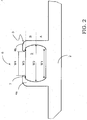
Figure 2 schematically shows a self clamping fork of the pipe housing of a vacuum solar thermal panel according to an embodiment of the present invention. - With reference to such figures, and in particular to
Figure 1 , a pipe housing of a vacuum solar thermal panel being realised according to an embodiment of the invention is shown and globally indicated with 1. - More in particular, the
pipe housing 1 comprises abase portion 2 and at least aretention element 3, in the form of a fork. - Advantageously according to an embodiment of the invention, the
retention element 3 comprises afirst tine 4a and asecond tine 4b both protruding from thebase portion 2 and being mirrored one another, and defining anopen housing space 5 therebetween having different widths starting from thebase portion 2 up to anopening inlet 6. Theopen housing space 5 will properly house apipe 10 of the vacuum solar thermal panel comprising thepipe housing 1. - In particular, the
tines retention element 3 thus comprises a first portion A having an increasing opening width from a first opening width W1 to a second opening width W2, being greater than the first opening width W1, and a second portion B having a decreasing opening width from the second opening width W2 to a third opening width W3, preferably equal to the first opening width W1. Advantageously according to an embodiment of the invention, the tines of theretention element 3 compriseretaining edges 7 at their tips, thus defining theopening inlet 6 which has a fourth opening width W4, which is smaller than the second opening width W2. - For instance, for a pipe having an external diameter equal to 10mm, the first opening width W1 and the third opening width W3 may be 11mm, the second opening width W2 may be 14.5mm and the fourth opening width W4 may be 9.5mm. In this way, the
retention element 3 provides for a self-retention of the pipe being housed into it, in particular in the vertical direction considering the local reference system ofFigure 1 . - In particular, the second opening width W2 is bigger than the pipe diameter while the fourth opening width W4 is smaller than the pipe diameter. Suitable values for the second opening width W2 are among 110-150% of the pipe diameter, while suitable values for the fourth opening width W4 are among 90-97% of the pipe diameter.
- In a preferred embodiment, the
retention element 3 is made of stainless steel and has a thickness of 2 mm having both elastic behaviour and strength to insert and then retain the pipe. - The mechanism of self-retention is enabled by the elastic behaviour of
retention element 3 in the form of a fork, having appropriate thicknesses of its tines, 4a and 4b, and the two retainingedges 7 at its tip. In particular, the thicknesses of the tines, 4a and 4b, of the 3 should be chosen in such a way that theretention element 3 shows an elastic behaviour when forced by asolar absorber pipe 10 as shown infigure 1 . - More in particular, once the
solar absorber pipe 10 is pressed against theretention element 3 in correspondence with itsopening inlet 6, it widens because of it elasticity to let thepipe 10 go inside theopen housing space 5. Then it closes back to its original width preventing thepipe 10 to move upward by means of the retaining edges 7 at its tip, as shown infigure 1 on a transverse assembly of thespacers 9 of the vacuum solar thermal panel. In particular,spacers 9 are disposed in a transverse direction with respect to thebase portions 2 of theretention elements 3. - Moreover, advantageously according to the invention, the
spacers 9 comprisesupright support elements 8 which abut against the glass plate of the vacuum solar thermal panel, traversing the selective metal sheet of the solar absorber provided with suitable holes. - It is to be remarked that the
pipe housing 1 of the vacuum solar thermal panel according to the invention avoids the risk of a vertical movement of the pipe and then of the solar absorber associate to thepipe 10 while allowing an easy insertion or mounting of the pipe itself during the assembly or manufacturing of the vacuum solar thermal panel. - In fact, the
tines retention element 3 provide a self-retention of the solar absorber pipe in the vertical direction. However, it should be underlined that theretention element 3 has a long thermal path because thehousing space 5 where thepipe 10 is accommodated is wider than the pipe diameter and the pipe can thus expand and move freely in the longitudinal direction within theretention element 3 without being allowed move upward or downward thanks to the retaining edges 7. - Moreover, the
pipe housing 1 of the vacuum solar thermal panel according to the invention, comprising thespacers 9 and theupright support elements 8 traversing thesolar absorber 11 provided withsuitable holes 8A, allows to further elongate the thermal path between the solar absorber and the glass plate, as well to use a continuoussolar absorber 11. - In fact, the continuous
solar absorber 11 of the vacuum solar thermal panel according to the present invention has an increased active area than the solar absorbers of the known solutions, for instance the one described in the PCT application published under No.WO 2009/149753 - On the contrary, advantageously according to the present invention, only
small holes 8A for theupright support elements 8 of thespacers 9 are to be provided in a single continuoussolar absorber 11 thus maximising its surface as well as minimising any shading caused by thespacers 9. - In this way, a vacuum solar thermal panel with a low conduction loss pipe housing, which allows for pipe self-retention in the vertical direction, is obtained.
- Obviously, for a technician of the field, aiming at meeting incidental and specific needs, several modifications to the above described vacuum solar thermal panel with pipe housing are possible within the scope of protection of the invention as defined by the following claims.
Claims (9)
- A vacuum solar thermal panel with pipe housing (1) for a solar absorber pipe (10) of the type comprising at least a base portion (2) and a retention element (3) for said pipe (10), said retention element (3) being in the form of a fork and comprising a first and a second tine (4a, 4b) protruding from the base portion (2), being mirrored one another, and defining an open housing space (5) wider than a diameter of said pipe (10), characterized in that said tines (4a, 4b) comprise retaining edges (7) at their tips and define an opening inlet (6) having a fourth opening width (W4) being smaller than the diameter of said pipe (10), said retention element (3) having an elastic behaviour such that, when the solar absorber pipe (10) is pressed against the retention element (3) in correspondence with its opening inlet (6), said retention element (3) widens to let the pipe (10) go inside the open housing space (5).
- The vacuum solar thermal panel with pipe housing (1) according to claim 1, characterized in that the open housing space (5) defined therebetween having different widths starting from said base portion (2) up to the opening inlet (6) for said pipe (10).
- The vacuum solar thermal panel with pipe housing (1) according to claim 2, characterized in that said retention element (3) comprises a first portion (A) having an increasing opening width from a first opening width (W1) to a second opening width (W2) greater than said first opening width (W1), and a second portion (C) having a decreasing opening width from said second opening width (W2) to a third opening width (W3).
- The vacuum solar thermal panel with pipe housing (1) according to claim 3, characterized in that said second opening width (W2) has a value in range of 110-150% of a diameter of said pipe (10).
- The vacuum solar thermal panel with pipe housing (1) according to claim 1, characterized in that said fourth opening width (W4) has a value in range of 90-97% of a diameter of said pipe (10).
- The vacuum solar thermal panel with pipe housing (1) according to any of the preceding claims, characterized in that said retention element (3) is made of stainless steel.
- The vacuum solar thermal panel with pipe housing (1) according to any of the preceding claims, characterized in that said base portion (2) and said retention element (3) with its tines (4a, 4b) have a same and substantially constant thickness.
- The vacuum solar thermal panel with pipe housing (1) according to any of the preceding claims, characterized in that it further comprises spacers (9) disposed in a transverse direction with respect to the base portions (2) of the retention elements (3) and provided with upright support elements (8) which abut against the glass plate of the vacuum solar thermal panel.
- The vacuum solar thermal panel with pipe housing (1) according to claim 8, characterized in that it further comprises a continuous solar absorber (11) provided with holes (8A) for allowing the upright support elements (8) of the spacers (9) to cross the continuous solar absorber (11) and abut against the glass plate of the vacuum solar thermal panel.
Priority Applications (2)
| Application Number | Priority Date | Filing Date | Title |
|---|---|---|---|
| EP10197369.1A EP2474795B1 (en) | 2010-12-30 | 2010-12-30 | Vacuum solar thermal panel with pipe housing |
| US13/339,398 US9404676B2 (en) | 2010-12-30 | 2011-12-29 | Vacuum solar thermal panel with pipe housing |
Applications Claiming Priority (1)
| Application Number | Priority Date | Filing Date | Title |
|---|---|---|---|
| EP10197369.1A EP2474795B1 (en) | 2010-12-30 | 2010-12-30 | Vacuum solar thermal panel with pipe housing |
Publications (2)
| Publication Number | Publication Date |
|---|---|
| EP2474795A1 EP2474795A1 (en) | 2012-07-11 |
| EP2474795B1 true EP2474795B1 (en) | 2016-04-27 |
Family
ID=43932021
Family Applications (1)
| Application Number | Title | Priority Date | Filing Date |
|---|---|---|---|
| EP10197369.1A Active EP2474795B1 (en) | 2010-12-30 | 2010-12-30 | Vacuum solar thermal panel with pipe housing |
Country Status (2)
| Country | Link |
|---|---|
| US (1) | US9404676B2 (en) |
| EP (1) | EP2474795B1 (en) |
Families Citing this family (3)
| Publication number | Priority date | Publication date | Assignee | Title |
|---|---|---|---|---|
| US10605467B2 (en) * | 2015-06-16 | 2020-03-31 | Mitsubishi Electric Corporation | Outdoor unit for air-conditioning apparatus and method of producing outdoor unit for air-conditioning apparatus |
| JP6744582B2 (en) * | 2017-03-30 | 2020-08-19 | 株式会社オートネットワーク技術研究所 | Wire harness |
| JP6744583B2 (en) * | 2017-03-30 | 2020-08-19 | 株式会社オートネットワーク技術研究所 | Route control member, clamp, and wire harness |
Family Cites Families (57)
| Publication number | Priority date | Publication date | Assignee | Title |
|---|---|---|---|---|
| US1334545A (en) * | 1920-01-16 | 1920-03-23 | C A Londelius & Sons Co | Pipe-support |
| US2038912A (en) * | 1930-04-04 | 1936-04-28 | Gen Motors Corp | Refrigerating apparatus |
| US2819858A (en) * | 1955-12-02 | 1958-01-14 | Avco Mfg Corp | Clip for defroster-heaters |
| US2896887A (en) * | 1957-05-06 | 1959-07-28 | Charles R Beltz | Clip |
| US3233852A (en) * | 1965-03-15 | 1966-02-08 | Raymond J Azar | Supporting shelf assembly |
| US3627300A (en) * | 1970-03-19 | 1971-12-14 | Panduit | Wire cable harness assembly apparatus |
| GB1404643A (en) * | 1972-09-23 | 1975-09-03 | Clarke Chapman Ltd | Heat exchanger |
| US3961619A (en) * | 1973-06-26 | 1976-06-08 | Solarsystems Incorporated | Flat plate solar collector module |
| US3952725A (en) * | 1974-06-24 | 1976-04-27 | Edmondson William B | Solar water heater |
| GB1533241A (en) * | 1975-01-20 | 1978-11-22 | Bennett C | Solar panels |
| JPS549170Y2 (en) * | 1975-06-13 | 1979-04-27 | ||
| US4122829A (en) * | 1976-07-09 | 1978-10-31 | Lowe Wallace A | Solar energy collector |
| US4164975A (en) * | 1976-08-18 | 1979-08-21 | Bottum Edward W | Heat exchanger holder |
| GB1541577A (en) * | 1976-10-06 | 1979-03-07 | Solar Apparatus & Equipment | Solar heating panels |
| US4213640A (en) * | 1978-05-04 | 1980-07-22 | Alfred Miles | Coupling for interconnecting conduits |
| US4289113A (en) * | 1979-07-27 | 1981-09-15 | Whittemore Peter G | Evacuated flat-plate solar collectors |
| DE2951362A1 (en) * | 1979-12-20 | 1981-07-02 | Erno Raumfahrttechnik Gmbh, 2800 Bremen | PLATE-SHAPED SOLAR PANEL |
| US4338994A (en) * | 1980-01-28 | 1982-07-13 | Bernd Hewing | Modular panel heater having improved holder devices |
| US4577435A (en) * | 1981-08-17 | 1986-03-25 | Springer Edward A | Micro-climate temperature control apparatus |
| JPS6138466U (en) * | 1984-08-10 | 1986-03-11 | 株式会社 パテイネ商会 | Holding device for cooling pipes for ice rinks |
| USD292554S (en) * | 1984-12-03 | 1987-11-03 | Kitagawa Industries Co., Ltd. | Electric wire clamp |
| USD293205S (en) * | 1985-01-03 | 1987-12-15 | Kitagawa Industries Co., Ltd. | Mini electric wire clamp |
| USD293207S (en) * | 1985-01-03 | 1987-12-15 | Kitagawa Industries Co., Ltd. | Electric wire clamp |
| US4681288A (en) * | 1985-09-04 | 1987-07-21 | Shinagawa Shoko Co., Ltd. | Fixing component |
| USD302938S (en) * | 1985-12-04 | 1989-08-22 | Kitagawa Industries Co., Ltd. | Wire holder |
| US4657069A (en) * | 1986-03-31 | 1987-04-14 | Deere & Company | Heat exchange tube retainer |
| DE3611764A1 (en) * | 1986-04-08 | 1987-10-15 | Bernd Kellner | VACUUM SOLAR COLLECTOR |
| US4709556A (en) * | 1986-11-17 | 1987-12-01 | Whirlpool Corporation | Heat exchanger tube retainer for a refrigerator condenser |
| EP0295542B1 (en) * | 1987-06-19 | 1993-03-10 | GRAFOPLAST S.p.A. | Open sleeve support for wire marking elements with snap lock |
| SE8902324L (en) * | 1989-06-27 | 1990-12-28 | Bengt Valdemar Eggemar | PROCEDURE AND DEVICE FOR HEAT EXCHANGE |
| US5074282A (en) * | 1990-10-24 | 1991-12-24 | Reed Peter D | Solar water heater |
| US5454428A (en) * | 1993-11-22 | 1995-10-03 | Radiant Engineering, Inc. | Hydronic radiant heat distribution panel and system |
| GB9400024D0 (en) * | 1994-01-04 | 1994-03-02 | Amp Gmbh | Centering spring support for panel mount connectors |
| US5467948A (en) * | 1994-06-27 | 1995-11-21 | Gillespie; Duncan S. | Apparatus for retaining cooling pipes for an ice rink |
| DE4430106A1 (en) * | 1994-08-25 | 1996-02-29 | Wolfgang Dr Spirkl | Solar heat collector with evacuated housing |
| US5743330A (en) * | 1996-09-09 | 1998-04-28 | Radiant Technology, Inc. | Radiant heat transfer panels |
| JP3960677B2 (en) * | 1998-02-16 | 2007-08-15 | 株式会社ニフコ | Stick-shaped object holder |
| US6557317B2 (en) * | 2001-06-29 | 2003-05-06 | Felix L. Sorkin | Concrete reinforcing bar support |
| CA2466624C (en) * | 2003-05-07 | 2007-01-02 | Dale H. Pickard | Hydronic radiant heat tubing receptacle and heat distribution panel system |
| US6969832B1 (en) * | 2003-05-19 | 2005-11-29 | Daughtry Sr Timothy Douglas | Radiant floor heating and cooling system clip |
| US6955168B2 (en) * | 2003-06-24 | 2005-10-18 | Kokusai Gijutsu Kaihatsu Kabushiki Kaisha | Solar heat collecting apparatus |
| EP1496320A1 (en) * | 2003-07-08 | 2005-01-12 | R & D du groupe Cockerill-Sambre | Flat solar panel with small thickness |
| DE102004040813A1 (en) * | 2003-12-03 | 2005-07-07 | Frank Drenkow | Plate-form radiation absorber has number of connecting sections of absorber tubes constructed as separately manufactured components and each with outwards orientated edge members parallel to longitudinal axis of absorber tubes |
| ES2291846T3 (en) * | 2004-01-22 | 2008-03-01 | European Organisation For Nuclear Research Cern | SOLAR COLLECTOR OF EVACUABLE FLAT PANEL. |
| US20050173597A1 (en) * | 2004-02-11 | 2005-08-11 | Patterson Ventilation Co., Inc. | Pipe and cable support apparatus and method |
| AT7834U1 (en) * | 2004-10-08 | 2005-09-26 | Bremstaller Ges M B H & Co Kg | HEAT EXCHANGER FOR A HOT WATER TANK |
| US7152831B2 (en) * | 2004-11-23 | 2006-12-26 | The Lamson & Sessions Co. | Conduit support |
| TWI255895B (en) * | 2005-05-26 | 2006-06-01 | Au Optronics Corp | Backlight module and lamp holder thereof |
| US20080011289A1 (en) * | 2006-07-14 | 2008-01-17 | National Science And Technology Development Agency | Photovoltaic thermal (PVT) collector |
| US7523898B1 (en) * | 2008-01-31 | 2009-04-28 | Sony Corporation | Wire holder with single step installation into T-shaped hole in support substrate |
| US8499823B1 (en) * | 2008-04-18 | 2013-08-06 | One Source | Twin heat transfer tubing retention panel |
| WO2009149753A1 (en) | 2008-06-11 | 2009-12-17 | R & B Energy Research Sarl | High efficiency evacuated solar panel |
| IT1390960B1 (en) | 2008-07-09 | 2011-10-27 | Tvp Solar Sa | SOLAR VACUUM THERMAL PANEL |
| IT1390985B1 (en) | 2008-08-26 | 2011-10-27 | Tvp Solar Sa | SOLAR THERMAL PANEL WITH EMPTY STRUCTURE OF LIGHT |
| US20100108825A1 (en) * | 2008-11-03 | 2010-05-06 | Brock Robert D | Foam support for line pipe |
| EP2211079A1 (en) * | 2009-01-23 | 2010-07-28 | AZ Pokorny S.R.O. | Attachment system for conduits and attachment method |
| USD654600S1 (en) * | 2010-12-02 | 2012-02-21 | Thomas Joseph Devine | Radiant tube securing panel |
-
2010
- 2010-12-30 EP EP10197369.1A patent/EP2474795B1/en active Active
-
2011
- 2011-12-29 US US13/339,398 patent/US9404676B2/en active Active
Also Published As
| Publication number | Publication date |
|---|---|
| US9404676B2 (en) | 2016-08-02 |
| US20120186578A1 (en) | 2012-07-26 |
| EP2474795A1 (en) | 2012-07-11 |
Similar Documents
| Publication | Publication Date | Title |
|---|---|---|
| EP1706678B1 (en) | Evacuable flat panel solar collector | |
| EP2474795B1 (en) | Vacuum solar thermal panel with pipe housing | |
| US4289113A (en) | Evacuated flat-plate solar collectors | |
| AU2009295584B2 (en) | Vacuum solar thermal panel with radiative screen | |
| EA200400753A1 (en) | SOLAR COLLECTOR FOR HEATING AIR USED FOR VENTILATION | |
| US10107522B2 (en) | Solar energy collecting module using vacuum panel | |
| CA2789728C (en) | An air channeling baffle for a furnace heat exchanger | |
| EP2908069B1 (en) | Solar thermal absorber element | |
| KR101512625B1 (en) | Evacuated solar panel with a non evaporable getter pump | |
| JP2015064138A (en) | Solar heat collection device | |
| US20110146667A1 (en) | High efficiency evacuated solar panel | |
| ES2656687T3 (en) | Clamping and arrangement device for absorber tubes | |
| US9638440B2 (en) | Solar boiler panel arrangement | |
| AU2008317530A1 (en) | Solar energy concentrator | |
| US9518764B2 (en) | Longer-life solar power plant receiver | |
| WO2007135419A2 (en) | Solar collector | |
| CN209910185U (en) | Solar heat collector | |
| KR20230098768A (en) | Vacuum adiabatic body | |
| EP3781880B1 (en) | Solar concentrator having a continuous parabolic reflective surface | |
| RU2463529C2 (en) | Evacuated solar panel with non-evaporable-getter-based pump | |
| EP2194333A2 (en) | Improved solar collector | |
| CN103517614A (en) | Heat radiation module combination method | |
| ITMI20002879A1 (en) | CENTRAL SOLAR RECEIVER |
Legal Events
| Date | Code | Title | Description |
|---|---|---|---|
| PUAI | Public reference made under article 153(3) epc to a published international application that has entered the european phase |
Free format text: ORIGINAL CODE: 0009012 |
|
| 17P | Request for examination filed |
Effective date: 20111012 |
|
| AK | Designated contracting states |
Kind code of ref document: A1 Designated state(s): AL AT BE BG CH CY CZ DE DK EE ES FI FR GB GR HR HU IE IS IT LI LT LU LV MC MK MT NL NO PL PT RO RS SE SI SK SM TR |
|
| AX | Request for extension of the european patent |
Extension state: BA ME |
|
| RIC1 | Information provided on ipc code assigned before grant |
Ipc: F24J 2/50 20060101AFI20141104BHEP Ipc: F24J 2/52 20060101ALN20141104BHEP |
|
| 17Q | First examination report despatched |
Effective date: 20141216 |
|
| RIC1 | Information provided on ipc code assigned before grant |
Ipc: F24J 2/50 20060101AFI20150402BHEP Ipc: F24J 2/52 20060101ALN20150402BHEP |
|
| GRAP | Despatch of communication of intention to grant a patent |
Free format text: ORIGINAL CODE: EPIDOSNIGR1 |
|
| INTG | Intention to grant announced |
Effective date: 20151116 |
|
| GRAS | Grant fee paid |
Free format text: ORIGINAL CODE: EPIDOSNIGR3 |
|
| GRAA | (expected) grant |
Free format text: ORIGINAL CODE: 0009210 |
|
| AK | Designated contracting states |
Kind code of ref document: B1 Designated state(s): AL AT BE BG CH CY CZ DE DK EE ES FI FR GB GR HR HU IE IS IT LI LT LU LV MC MK MT NL NO PL PT RO RS SE SI SK SM TR |
|
| REG | Reference to a national code |
Ref country code: GB Ref legal event code: FG4D |
|
| REG | Reference to a national code |
Ref country code: CH Ref legal event code: EP |
|
| REG | Reference to a national code |
Ref country code: AT Ref legal event code: REF Ref document number: 795263 Country of ref document: AT Kind code of ref document: T Effective date: 20160515 |
|
| REG | Reference to a national code |
Ref country code: IE Ref legal event code: FG4D |
|
| REG | Reference to a national code |
Ref country code: DE Ref legal event code: R096 Ref document number: 602010032790 Country of ref document: DE |
|
| REG | Reference to a national code |
Ref country code: CH Ref legal event code: NV Representative=s name: ING. MARCO ZARDI C/O M. ZARDI AND CO. S.A., CH |
|
| REG | Reference to a national code |
Ref country code: LT Ref legal event code: MG4D |
|
| REG | Reference to a national code |
Ref country code: NL Ref legal event code: MP Effective date: 20160427 |
|
| REG | Reference to a national code |
Ref country code: AT Ref legal event code: MK05 Ref document number: 795263 Country of ref document: AT Kind code of ref document: T Effective date: 20160427 |
|
| PG25 | Lapsed in a contracting state [announced via postgrant information from national office to epo] |
Ref country code: NL Free format text: LAPSE BECAUSE OF FAILURE TO SUBMIT A TRANSLATION OF THE DESCRIPTION OR TO PAY THE FEE WITHIN THE PRESCRIBED TIME-LIMIT Effective date: 20160427 |
|
| PG25 | Lapsed in a contracting state [announced via postgrant information from national office to epo] |
Ref country code: PL Free format text: LAPSE BECAUSE OF FAILURE TO SUBMIT A TRANSLATION OF THE DESCRIPTION OR TO PAY THE FEE WITHIN THE PRESCRIBED TIME-LIMIT Effective date: 20160427 Ref country code: LT Free format text: LAPSE BECAUSE OF FAILURE TO SUBMIT A TRANSLATION OF THE DESCRIPTION OR TO PAY THE FEE WITHIN THE PRESCRIBED TIME-LIMIT Effective date: 20160427 Ref country code: NO Free format text: LAPSE BECAUSE OF FAILURE TO SUBMIT A TRANSLATION OF THE DESCRIPTION OR TO PAY THE FEE WITHIN THE PRESCRIBED TIME-LIMIT Effective date: 20160727 Ref country code: FI Free format text: LAPSE BECAUSE OF FAILURE TO SUBMIT A TRANSLATION OF THE DESCRIPTION OR TO PAY THE FEE WITHIN THE PRESCRIBED TIME-LIMIT Effective date: 20160427 |
|
| REG | Reference to a national code |
Ref country code: FR Ref legal event code: PLFP Year of fee payment: 7 |
|
| PG25 | Lapsed in a contracting state [announced via postgrant information from national office to epo] |
Ref country code: RS Free format text: LAPSE BECAUSE OF FAILURE TO SUBMIT A TRANSLATION OF THE DESCRIPTION OR TO PAY THE FEE WITHIN THE PRESCRIBED TIME-LIMIT Effective date: 20160427 Ref country code: ES Free format text: LAPSE BECAUSE OF FAILURE TO SUBMIT A TRANSLATION OF THE DESCRIPTION OR TO PAY THE FEE WITHIN THE PRESCRIBED TIME-LIMIT Effective date: 20160427 Ref country code: PT Free format text: LAPSE BECAUSE OF FAILURE TO SUBMIT A TRANSLATION OF THE DESCRIPTION OR TO PAY THE FEE WITHIN THE PRESCRIBED TIME-LIMIT Effective date: 20160829 Ref country code: GR Free format text: LAPSE BECAUSE OF FAILURE TO SUBMIT A TRANSLATION OF THE DESCRIPTION OR TO PAY THE FEE WITHIN THE PRESCRIBED TIME-LIMIT Effective date: 20160728 Ref country code: SE Free format text: LAPSE BECAUSE OF FAILURE TO SUBMIT A TRANSLATION OF THE DESCRIPTION OR TO PAY THE FEE WITHIN THE PRESCRIBED TIME-LIMIT Effective date: 20160427 Ref country code: AT Free format text: LAPSE BECAUSE OF FAILURE TO SUBMIT A TRANSLATION OF THE DESCRIPTION OR TO PAY THE FEE WITHIN THE PRESCRIBED TIME-LIMIT Effective date: 20160427 Ref country code: LV Free format text: LAPSE BECAUSE OF FAILURE TO SUBMIT A TRANSLATION OF THE DESCRIPTION OR TO PAY THE FEE WITHIN THE PRESCRIBED TIME-LIMIT Effective date: 20160427 Ref country code: HR Free format text: LAPSE BECAUSE OF FAILURE TO SUBMIT A TRANSLATION OF THE DESCRIPTION OR TO PAY THE FEE WITHIN THE PRESCRIBED TIME-LIMIT Effective date: 20160427 |
|
| PG25 | Lapsed in a contracting state [announced via postgrant information from national office to epo] |
Ref country code: BE Free format text: LAPSE BECAUSE OF FAILURE TO SUBMIT A TRANSLATION OF THE DESCRIPTION OR TO PAY THE FEE WITHIN THE PRESCRIBED TIME-LIMIT Effective date: 20160427 |
|
| REG | Reference to a national code |
Ref country code: DE Ref legal event code: R097 Ref document number: 602010032790 Country of ref document: DE |
|
| PG25 | Lapsed in a contracting state [announced via postgrant information from national office to epo] |
Ref country code: CZ Free format text: LAPSE BECAUSE OF FAILURE TO SUBMIT A TRANSLATION OF THE DESCRIPTION OR TO PAY THE FEE WITHIN THE PRESCRIBED TIME-LIMIT Effective date: 20160427 Ref country code: RO Free format text: LAPSE BECAUSE OF FAILURE TO SUBMIT A TRANSLATION OF THE DESCRIPTION OR TO PAY THE FEE WITHIN THE PRESCRIBED TIME-LIMIT Effective date: 20160427 Ref country code: DK Free format text: LAPSE BECAUSE OF FAILURE TO SUBMIT A TRANSLATION OF THE DESCRIPTION OR TO PAY THE FEE WITHIN THE PRESCRIBED TIME-LIMIT Effective date: 20160427 Ref country code: SK Free format text: LAPSE BECAUSE OF FAILURE TO SUBMIT A TRANSLATION OF THE DESCRIPTION OR TO PAY THE FEE WITHIN THE PRESCRIBED TIME-LIMIT Effective date: 20160427 Ref country code: EE Free format text: LAPSE BECAUSE OF FAILURE TO SUBMIT A TRANSLATION OF THE DESCRIPTION OR TO PAY THE FEE WITHIN THE PRESCRIBED TIME-LIMIT Effective date: 20160427 |
|
| PG25 | Lapsed in a contracting state [announced via postgrant information from national office to epo] |
Ref country code: SM Free format text: LAPSE BECAUSE OF FAILURE TO SUBMIT A TRANSLATION OF THE DESCRIPTION OR TO PAY THE FEE WITHIN THE PRESCRIBED TIME-LIMIT Effective date: 20160427 |
|
| PLBE | No opposition filed within time limit |
Free format text: ORIGINAL CODE: 0009261 |
|
| STAA | Information on the status of an ep patent application or granted ep patent |
Free format text: STATUS: NO OPPOSITION FILED WITHIN TIME LIMIT |
|
| 26N | No opposition filed |
Effective date: 20170130 |
|
| PG25 | Lapsed in a contracting state [announced via postgrant information from national office to epo] |
Ref country code: SI Free format text: LAPSE BECAUSE OF FAILURE TO SUBMIT A TRANSLATION OF THE DESCRIPTION OR TO PAY THE FEE WITHIN THE PRESCRIBED TIME-LIMIT Effective date: 20160427 |
|
| PG25 | Lapsed in a contracting state [announced via postgrant information from national office to epo] |
Ref country code: MC Free format text: LAPSE BECAUSE OF FAILURE TO SUBMIT A TRANSLATION OF THE DESCRIPTION OR TO PAY THE FEE WITHIN THE PRESCRIBED TIME-LIMIT Effective date: 20160427 |
|
| REG | Reference to a national code |
Ref country code: IE Ref legal event code: MM4A |
|
| PG25 | Lapsed in a contracting state [announced via postgrant information from national office to epo] |
Ref country code: LU Free format text: LAPSE BECAUSE OF NON-PAYMENT OF DUE FEES Effective date: 20161230 |
|
| REG | Reference to a national code |
Ref country code: FR Ref legal event code: PLFP Year of fee payment: 8 |
|
| REG | Reference to a national code |
Ref country code: DE Ref legal event code: R079 Ref document number: 602010032790 Country of ref document: DE Free format text: PREVIOUS MAIN CLASS: F24J0002500000 Ipc: F24S0080500000 |
|
| PG25 | Lapsed in a contracting state [announced via postgrant information from national office to epo] |
Ref country code: IE Free format text: LAPSE BECAUSE OF NON-PAYMENT OF DUE FEES Effective date: 20161230 |
|
| PG25 | Lapsed in a contracting state [announced via postgrant information from national office to epo] |
Ref country code: CY Free format text: LAPSE BECAUSE OF FAILURE TO SUBMIT A TRANSLATION OF THE DESCRIPTION OR TO PAY THE FEE WITHIN THE PRESCRIBED TIME-LIMIT Effective date: 20160427 Ref country code: HU Free format text: LAPSE BECAUSE OF FAILURE TO SUBMIT A TRANSLATION OF THE DESCRIPTION OR TO PAY THE FEE WITHIN THE PRESCRIBED TIME-LIMIT; INVALID AB INITIO Effective date: 20101230 |
|
| PG25 | Lapsed in a contracting state [announced via postgrant information from national office to epo] |
Ref country code: MK Free format text: LAPSE BECAUSE OF FAILURE TO SUBMIT A TRANSLATION OF THE DESCRIPTION OR TO PAY THE FEE WITHIN THE PRESCRIBED TIME-LIMIT Effective date: 20160427 Ref country code: TR Free format text: LAPSE BECAUSE OF FAILURE TO SUBMIT A TRANSLATION OF THE DESCRIPTION OR TO PAY THE FEE WITHIN THE PRESCRIBED TIME-LIMIT Effective date: 20160427 Ref country code: IS Free format text: LAPSE BECAUSE OF FAILURE TO SUBMIT A TRANSLATION OF THE DESCRIPTION OR TO PAY THE FEE WITHIN THE PRESCRIBED TIME-LIMIT Effective date: 20160427 |
|
| PG25 | Lapsed in a contracting state [announced via postgrant information from national office to epo] |
Ref country code: BG Free format text: LAPSE BECAUSE OF FAILURE TO SUBMIT A TRANSLATION OF THE DESCRIPTION OR TO PAY THE FEE WITHIN THE PRESCRIBED TIME-LIMIT Effective date: 20160427 |
|
| PG25 | Lapsed in a contracting state [announced via postgrant information from national office to epo] |
Ref country code: MT Free format text: LAPSE BECAUSE OF NON-PAYMENT OF DUE FEES Effective date: 20161230 |
|
| PG25 | Lapsed in a contracting state [announced via postgrant information from national office to epo] |
Ref country code: AL Free format text: LAPSE BECAUSE OF FAILURE TO SUBMIT A TRANSLATION OF THE DESCRIPTION OR TO PAY THE FEE WITHIN THE PRESCRIBED TIME-LIMIT Effective date: 20160427 |
|
| PGFP | Annual fee paid to national office [announced via postgrant information from national office to epo] |
Ref country code: CH Payment date: 20230101 Year of fee payment: 13 |
|
| P01 | Opt-out of the competence of the unified patent court (upc) registered |
Effective date: 20230512 |
|
| PGFP | Annual fee paid to national office [announced via postgrant information from national office to epo] |
Ref country code: GB Payment date: 20231219 Year of fee payment: 14 |
|
| PGFP | Annual fee paid to national office [announced via postgrant information from national office to epo] |
Ref country code: IT Payment date: 20231221 Year of fee payment: 14 Ref country code: FR Payment date: 20231219 Year of fee payment: 14 Ref country code: DE Payment date: 20231206 Year of fee payment: 14 |