EP2474435A1 - Cooling air intake structure for v-belt type stepless transmission - Google Patents
Cooling air intake structure for v-belt type stepless transmission Download PDFInfo
- Publication number
- EP2474435A1 EP2474435A1 EP09848976A EP09848976A EP2474435A1 EP 2474435 A1 EP2474435 A1 EP 2474435A1 EP 09848976 A EP09848976 A EP 09848976A EP 09848976 A EP09848976 A EP 09848976A EP 2474435 A1 EP2474435 A1 EP 2474435A1
- Authority
- EP
- European Patent Office
- Prior art keywords
- cooling air
- transmission case
- side opening
- intake structure
- cooling
- Prior art date
- Legal status (The legal status is an assumption and is not a legal conclusion. Google has not performed a legal analysis and makes no representation as to the accuracy of the status listed.)
- Granted
Links
Images


Classifications
-
- F—MECHANICAL ENGINEERING; LIGHTING; HEATING; WEAPONS; BLASTING
- F16—ENGINEERING ELEMENTS AND UNITS; GENERAL MEASURES FOR PRODUCING AND MAINTAINING EFFECTIVE FUNCTIONING OF MACHINES OR INSTALLATIONS; THERMAL INSULATION IN GENERAL
- F16H—GEARING
- F16H57/00—General details of gearing
- F16H57/02—Gearboxes; Mounting gearing therein
-
- F—MECHANICAL ENGINEERING; LIGHTING; HEATING; WEAPONS; BLASTING
- F16—ENGINEERING ELEMENTS AND UNITS; GENERAL MEASURES FOR PRODUCING AND MAINTAINING EFFECTIVE FUNCTIONING OF MACHINES OR INSTALLATIONS; THERMAL INSULATION IN GENERAL
- F16H—GEARING
- F16H57/00—General details of gearing
- F16H57/04—Features relating to lubrication or cooling or heating
- F16H57/048—Type of gearings to be lubricated, cooled or heated
- F16H57/0487—Friction gearings
- F16H57/0489—Friction gearings with endless flexible members, e.g. belt CVTs
-
- B—PERFORMING OPERATIONS; TRANSPORTING
- B60—VEHICLES IN GENERAL
- B60K—ARRANGEMENT OR MOUNTING OF PROPULSION UNITS OR OF TRANSMISSIONS IN VEHICLES; ARRANGEMENT OR MOUNTING OF PLURAL DIVERSE PRIME-MOVERS IN VEHICLES; AUXILIARY DRIVES FOR VEHICLES; INSTRUMENTATION OR DASHBOARDS FOR VEHICLES; ARRANGEMENTS IN CONNECTION WITH COOLING, AIR INTAKE, GAS EXHAUST OR FUEL SUPPLY OF PROPULSION UNITS IN VEHICLES
- B60K11/00—Arrangement in connection with cooling of propulsion units
- B60K11/08—Air inlets for cooling; Shutters or blinds therefor
-
- B—PERFORMING OPERATIONS; TRANSPORTING
- B60—VEHICLES IN GENERAL
- B60K—ARRANGEMENT OR MOUNTING OF PROPULSION UNITS OR OF TRANSMISSIONS IN VEHICLES; ARRANGEMENT OR MOUNTING OF PLURAL DIVERSE PRIME-MOVERS IN VEHICLES; AUXILIARY DRIVES FOR VEHICLES; INSTRUMENTATION OR DASHBOARDS FOR VEHICLES; ARRANGEMENTS IN CONNECTION WITH COOLING, AIR INTAKE, GAS EXHAUST OR FUEL SUPPLY OF PROPULSION UNITS IN VEHICLES
- B60K17/00—Arrangement or mounting of transmissions in vehicles
- B60K17/04—Arrangement or mounting of transmissions in vehicles characterised by arrangement, location or kind of gearing
- B60K17/06—Arrangement or mounting of transmissions in vehicles characterised by arrangement, location or kind of gearing of change-speed gearing
- B60K17/08—Arrangement or mounting of transmissions in vehicles characterised by arrangement, location or kind of gearing of change-speed gearing of mechanical type
-
- B—PERFORMING OPERATIONS; TRANSPORTING
- B62—LAND VEHICLES FOR TRAVELLING OTHERWISE THAN ON RAILS
- B62J—CYCLE SADDLES OR SEATS; AUXILIARY DEVICES OR ACCESSORIES SPECIALLY ADAPTED TO CYCLES AND NOT OTHERWISE PROVIDED FOR, e.g. ARTICLE CARRIERS OR CYCLE PROTECTORS
- B62J50/00—Arrangements specially adapted for use on cycles not provided for in main groups B62J1/00 - B62J45/00
- B62J50/30—Means for ventilation within devices provided on the cycle, e.g. ventilation means in a battery container
-
- B—PERFORMING OPERATIONS; TRANSPORTING
- B62—LAND VEHICLES FOR TRAVELLING OTHERWISE THAN ON RAILS
- B62M—RIDER PROPULSION OF WHEELED VEHICLES OR SLEDGES; POWERED PROPULSION OF SLEDGES OR SINGLE-TRACK CYCLES; TRANSMISSIONS SPECIALLY ADAPTED FOR SUCH VEHICLES
- B62M7/00—Motorcycles characterised by position of motor or engine
-
- F—MECHANICAL ENGINEERING; LIGHTING; HEATING; WEAPONS; BLASTING
- F16—ENGINEERING ELEMENTS AND UNITS; GENERAL MEASURES FOR PRODUCING AND MAINTAINING EFFECTIVE FUNCTIONING OF MACHINES OR INSTALLATIONS; THERMAL INSULATION IN GENERAL
- F16H—GEARING
- F16H57/00—General details of gearing
- F16H57/02—Gearboxes; Mounting gearing therein
- F16H57/035—Gearboxes for gearing with endless flexible members
-
- B—PERFORMING OPERATIONS; TRANSPORTING
- B60—VEHICLES IN GENERAL
- B60Y—INDEXING SCHEME RELATING TO ASPECTS CROSS-CUTTING VEHICLE TECHNOLOGY
- B60Y2200/00—Type of vehicle
- B60Y2200/10—Road Vehicles
- B60Y2200/12—Motorcycles, Trikes; Quads; Scooters
-
- B—PERFORMING OPERATIONS; TRANSPORTING
- B60—VEHICLES IN GENERAL
- B60Y—INDEXING SCHEME RELATING TO ASPECTS CROSS-CUTTING VEHICLE TECHNOLOGY
- B60Y2200/00—Type of vehicle
- B60Y2200/10—Road Vehicles
- B60Y2200/12—Motorcycles, Trikes; Quads; Scooters
- B60Y2200/126—Scooters
-
- F—MECHANICAL ENGINEERING; LIGHTING; HEATING; WEAPONS; BLASTING
- F16—ENGINEERING ELEMENTS AND UNITS; GENERAL MEASURES FOR PRODUCING AND MAINTAINING EFFECTIVE FUNCTIONING OF MACHINES OR INSTALLATIONS; THERMAL INSULATION IN GENERAL
- F16H—GEARING
- F16H57/00—General details of gearing
- F16H57/02—Gearboxes; Mounting gearing therein
- F16H2057/0203—Gearboxes; Mounting gearing therein the gearbox is associated or combined with a crank case of an engine
-
- F—MECHANICAL ENGINEERING; LIGHTING; HEATING; WEAPONS; BLASTING
- F16—ENGINEERING ELEMENTS AND UNITS; GENERAL MEASURES FOR PRODUCING AND MAINTAINING EFFECTIVE FUNCTIONING OF MACHINES OR INSTALLATIONS; THERMAL INSULATION IN GENERAL
- F16H—GEARING
- F16H57/00—General details of gearing
- F16H57/02—Gearboxes; Mounting gearing therein
- F16H2057/02039—Gearboxes for particular applications
- F16H2057/02043—Gearboxes for particular applications for vehicle transmissions
- F16H2057/02065—Gearboxes for particular applications for vehicle transmissions for motorcycles or squads
-
- F—MECHANICAL ENGINEERING; LIGHTING; HEATING; WEAPONS; BLASTING
- F16—ENGINEERING ELEMENTS AND UNITS; GENERAL MEASURES FOR PRODUCING AND MAINTAINING EFFECTIVE FUNCTIONING OF MACHINES OR INSTALLATIONS; THERMAL INSULATION IN GENERAL
- F16H—GEARING
- F16H57/00—General details of gearing
- F16H57/04—Features relating to lubrication or cooling or heating
- F16H57/0412—Cooling or heating; Control of temperature
- F16H57/0415—Air cooling or ventilation; Heat exchangers; Thermal insulations
- F16H57/0416—Air cooling or ventilation
Definitions
- the present invention relates to a cooling air intake structure for taking cooling air into the V-belt drive continuously variable transmission when those component parts need cooling.
- a known air intake structure described in Patent Literature 1 has an air inlet opening toward the rear of the vehicle. This cooling air intake structure is effective in preventing muddy water and dust coming from the front from entering the cooling air intake structure, but is not necessarily effective in preventing muddy water and dust raised up by the rear wheel from entering the cooling air intake structure.
- Patent Literature 1 JP Utility Model Publication S63-17695 ( Fig.5 )
- a cooling air intake structure for a V-belt drive continuously variable transmission disposed beside the rear wheel of a small vehicle characterized in that a cooling air inlet through which cooling air is taken in is formed at a position beside a transmission case and above a cooling fan side opening formed in the transmission case opposite to a drive pulley; and a cooling air passage extending from the cooling air inlet to the side opening is formed in a manner surrounding the side opening.
- the cooling air passage is formed in the shape of an inverted letter U such that cooling air taken in through the cooling air inlet formed at the position in an upper part of a space beside the transmission case flows upward first and then flows downward to the cooling fan side opening of the transmission case.
- the cooling air inlet extends along an edge of a body cover.
- the body cover is provided with pillion footrests, and the cooling air passage is formed in a space covered with the body cover extending below the pillion footrest.
- an air cleaner is disposed above the transmission case such that an inlet of the air cleaner is above a cooling air duct forming the cooling air passage having the shape of an inverted letter U.
- the cooling air passage is formed in the cooling air duct, and the cooling air duct covers the side opening formed in the transmission case and is attached to a flat part of the transmission case beside the drive pulley.
- the cooling air duct is fastened to the transmission case with fastening members arranged on front and rear sides of the side opening formed in the transmission case.
- At least a part of the cooling air inlet is positioned in an area which is beside the drive pulley of the V-belt drive continuously variable transmission and which has a diameter equal to that of the drive pulley.
- cooling air flows in the cooling air duct along the U-shaped passage, and then flows rearward along an L-shaped passage to the cooling fan side opening.
- a vibration isolating member is placed between the cooling air duct and the transmission case.
- the cooling air inlet can be spaced a long distance apart from muddy water and dust flung up by the rear wheel.
- the cooling air duct can be formed in a small size. Therefore, entry of muddy water and dust into the cooling air inlet can be suppressed.
- the cooling air intake structure has the advantage of preventing muddy water flowing along the upper surface of the transmission case from flowing into the transmission case.
- Muddy water and dust can be separated from cooling air by the U-shaped cooling air passage. Therefore, if the cooling air intake structure is provided with a filter, the life of the filter can be extended.
- the cooling air passage is formed in a space covered with a laterally protruding side skirt of the body cover below the pillion footrest. Therefore, cooling air can flow smoothly through the space inside the side skirt to the cooling air inlet.
- Intake air can flow smoothly through the cooling air passage to the inlet of the air cleaner. Consequently, the performance of the internal combustion engine can be improved.
- the cooling air duct is attached to the flat part beside the drive pulley. Therefore, intake noise generated by intake air flowing through the cooling fan side opening formed in the transmission case can be absorbed and noise suppressing effect can be improved.
- the cooling air duct can firmly be attached to the transmission case with the fastening members arranged on the front and rear sides of the side opening.
- cooling air inlet can be spaced a long distance apart from dust flung up by the rear wheel without increasing the size of a front part of the V-belt drive continuously variable transmission, entrance of dust into the transmission can be suppressed.
- Cooling air passage 71 ... Cooling air inlet, 74 ... U-shaped part, 75 ... L-shaped part, 76 ... Fastening member, 77 ... Space of a diameter equal to the diameter of the drive pulley 40, 78 ... Edge of the body cover, 79 ... Pillion footrest, 81 ... Flow of cooling air, 82 ... Flow of intake air in the air cleaner DESCRIPTION OF THE EMBODIMENTS
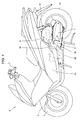
- Fig. 1 is a side elevation of a motorcycle 2 provided with a power unit 1 relating to a preferred embodiment of the present invention.
- the motorcycle 2 has a body frame formed by assembling a head pipe, a main frame extending obliquely downward toward the rear from the head pipe, right and left rear frames connected to the rear end of the main frame and extending obliquely upward toward the rear, and some frames.
- a front wheel 4 is rotatably supported on the lower end of a front fork 3 which is rotatably supported on the head pipe.
- a handlebar 5 is connected to an upper end part of the front fork 3.
- the power unit 1 is suspended from the rear frame by connecting a hanger 6 ( Fig. 2 ) formed integrally with a front part of the power unit 1 to a bracket fixed to the rear frame by a support shaft 7.
- a rear cushion 8 is extended between a bracket 14 ( Fig. 2 ) formed on a rear end part of the power unit 1, and a bracket formed on a rear end part of the rear frame.
- the power unit 1 is suspended for swinging with the axis of its cylinder slightly inclined upward toward the front.
- a rear wheel 10 is mounted on a rear axle 9 ( Fig. 3 ) extending to the right from a rear part of the power unit 1.
- the rear axle 9 is driven by the power unit 1.
- An air cleaner 11 is disposed above the power unit 1.
- Fig. 2 is a vertical sectional view of the power unit 1 as viewed from the left side. Terms modified by front, rear, right and left, are used for indicating positions, sides and parts on the front, rear, right and left sides, respectively, of the vehicle provided with the power unit.
- the power unit 1 includes an internal combustion engine 16 and a transmission 17 extending toward the rear from the left side of the internal combustion engine 16.
- the transmission 17 includes a V-belt drive continuously variable transmission 18 and a reduction gear 19.
- the engine 16 is a rocker arm type, water-cooled, four-stroke cycle, overhead valve, single-cylinder internal combustion engine.
- An intake pipe 20 has one end connected to an intake port formed in an upper part of a cylinder head 25 and the other end connected to a throttle body 21.
- the air cleaner 11 ( Fig. 1 ) is connected to the inlet end of the throttle body 21.
- a fuel injection valve 22 is connected to the intake pipe 20.
- a gear case breather hose 39 is extended from an upper part of a gear case 38 and is connected to the intake chamber of the air cleaner 11.
- a speed sensor 49 is connected to an upper part of the gear case 38. The speed sensor 49 senses the tip speed of a gear 48 ( Fig. 3 ) mounted on the rear axle 9 to determine a vehicle speed.
- Fig. 3 shows a sectional view taken on the line III-III in Fig. 2 .
- the engine body of the internal combustion engine 16 is formed of a crankcase 23, a cylinder block 24 connected to the front end of the crankcase 23, a cylinder head 25 connected to the front end of the cylinder block 24, and a cylinder head cover 26 put on the cylinder head 25.
- the crankcase 23 is formed by joining together a left half crankcase 23L and a right half crankcase 23R.
- a crankshaft 27 is supported for rotation in ball bearings 28A and 28B supported on the crankcase 23.
- a piston 29 is slidably fitted in a cylinder bore 30 formed in the cylinder block 24.
- the piston 29 is connected to the crankpin 32 of the crankshaft 27 by a connecting rod 31.
- the piston 29 reciprocates to drive the crankshaft 27 for rotation.
- a combustion chamber 33 is formed in the bottom surface of the cylinder head 25 opposite to the top surface of the piston 29.
- a spark plug 34 is attached to the cylinder head 25 such that the axis thereof is tilted to the left with respect to the center axis of the cylinder bore 30.
- the transmission 17 is made up of the V-belt drive continuously variable transmission 18 and the reduction gear 19.
- the V-belt drive continuously variable transmission 18 is covered with a transmission case 37.
- the transmission case 37 has a right half transmission case 37R and a left half transmission case 37L.
- the right half transmission case 37R is fixedly connected to the left half crankcase 23L.
- the right half transmission case 37R and the left half transmission case 37L are fastened together with bolts.
- the reduction gear 19 is covered with a rear part of the right half transmission case 37R and the gear case 38.
- the gear case 38 is fastened to the right half transmission case 37R with bolts.
- the crankshaft 27 serves as the drive shaft of the V-belt drive continuously variable transmission 18.
- a drive pulley 40 included in the V-belt drive continuously variable transmission 18 is mounted on a left part of the crankshaft 27.
- a driven shaft 41 is supported for rotation in bearings 42A, 42B and 42C supported on the left half transmission case 37L, the right half transmission case 37R and the gear case 38.
- a driven pulley 44 is interlocked with the driven shaft 41 by a centrifugal clutch 43 mounted on the driven shaft 41.
- An endless V-belt 45 is extended between the drive pulley 40 and the driven pulley 44.
- the drive pulley 40 includes a fixed half part 40A, a movable half part 40B, weight rollers 40C and a ramp plate 40D.
- the driven pulley 44 includes a fixed half part 44A, a movable half part 44B, a rotating sleeve 44C and a coil spring 44D.
- the centrifugal clutch 43 includes an outer clutch member 43A and an inner clutch member 43B. The outer clutch member 43A is interlocked with the driven shaft 41. The inner clutch member 43B is connected to the rotating sleeve 44C.
- the weight rollers 40C placed in a space between the movable half part 40B and the ramp plate 40D are moved radially outward by centrifugal force and the movable half part 40B is pushed by the weight rollers 40C toward the fixed half part 40A to increase the working pitch diameter of the drive pulley 40 and tensile stress induced in the V-belt 45 increases. Consequently, the movable half part 44B of the driven pulley 44 is moved against the resilience of the coil spring 44D, the distance between the fixed half part 44A and the movable half part 44B increases and the working pitch diameter of the driven pulley 44 is diminished.
- the rotational speed of the driven pulley 44 increases when the ratio of the working pitch diameter of the drive pulley 40 to that of the driven pulley 44 is thus increased.
- the rotation of the driven pulley 44 is transmitted through the rotating sleeve 44C to the inner clutch member 43B of the centrifugal clutch 43, the centrifugal clutch 43 is engaged and the rotation of the driven pulley 44 is transmitted to the driven shaft 41.
- the driven shaft 41 serves also as the input shaft of the reduction gear 19.
- a drive pinion 41a is formed integrally with the driven shaft 41.
- the rear axle 9 united with the rear wheel 10 is supported for rotation on the right half transmission case 37R and the gear case 38.
- An intermediate shaft 46 disposed between the driven shaft 41 and the rear axle 9 is supported for rotation on the right half transmission case 37R and the gear case 38.
- An intermediate gear 47 is fixedly mounted on the intermediate shaft 46 and is engaged with the drive pinion 41a.
- An intermediate pinion 46a is formed integrally with the intermediate shaft 46.
- a rear axle gear 48 is fixedly mounted on the rear axle 9 and is engaged with the intermediate pinion 46a.
- the torque of the driven shaft 41 is transmitted through the drive pinion 41a, the intermediate gear 47, the intermediate shaft 46, the intermediate pinion 46a and the rear axle gear 48 to the rear axle 9.
- the rotational speed of the rear axle 9 is far lower than that of the driven shaft 41 to drive the rear wheel 10 on the rear axle 9 at a reduced rotational speed.
- a centrifugal cooling fan 51 is formed integrally with the fixed half part 40A of the drive pulley 40 on the left surface, namely, the back surface, of the fixed half part 40A.
- the cooling fan 51 sucks cooling air through the cooling air duct 50 and a side opening 52 formed in the left half transmission case 37L opposite to the cooling fan 51 to cool the continuously variable transmission 18.
- Air used for cooling the V-belt drive continuously variable transmission 18 is discharged to the outside through an outlet opening 53 ( Fig.
- the cooling air duct 50 is placed at a position corresponding to a front part of the left half transmission case 37L.
- the cooling air duct 50 has an inner duct member 50A and an outer duct member 50B.
- Fig. 4 shows a sectional view of the left half transmission case 37L taken in a horizontal plane
- Fig. 5 shows a side elevation of the left half transmission case 37L taken from the left side in the direction of the arrow V in Fig. 4
- a front part of the left half transmission case 37L corresponding to the drive pulley 40 has a flat part 56.
- the cooling air duct 50 is attached to the flat part 56.
- the side opening 52 namely, a cooling air inlet, is formed in a central part of the flat part 56.
- Bolt holes 57 for bolts for fastening together the right half transmission case 37R and the left half transmission case 37L are formed in a peripheral part and a middle part of the left half transmission case 37L. As shown in Fig.
- bolts 58 are passed through the bolt holes 57 in the middle part and a rear part to fasten the left half transmission case 37L to the right half transmission case 37R.
- Three internally threaded holes 59 are formed in a front part of the left half transmission case 37L for bolts for fastening the cooling air duct 50 to the left half transmission case 37L.
- Fig. 6 shows an enlarged sectional view of the inner duct member 50A of the cooling air duct 50 taken in a horizontal plane and Fig. 7 shows a side elevation of the inner duct member 50A of the cooling air duct 50 as viewed from the left side in the direction of the arrow VII.
- Fig. 6 is a sectional view taken on the line VI-VI in Fig. 7 .
- a cooling air outlet 62 is formed in a central part of the inner duct member 50A of the cooling air duct 50, which is opposite to the side opening 52 of the left half transmission case 37L.
- a circular sealing groove 63 is formed in the inner surface of the inner duct member 50A facing the left half transmission case 37L, so as to correspond to a part of the left half transmission case 37L surrounding the side opening 52 opposite the cooling fan.
- An O-ring is fitted in the circular sealing groove 63.
- a sealing groove 64 is formed in the left surface, namely, the outer surface, of the inner duct member 50A so as to extend along a part of the peripheral part and around a central part of the left surface.
- An edge part of the guide wall 67 of the outer duct member 50B of the cooling air duct 50 is fitted in the sealing groove 64.
- the inner duct member 50A is provided with three bolt holes 65 for bolts for fastening the cooling air duct 50.
- Fig. 8 shows an enlarged sectional view of the outer duct member 50B of the cooling air duct 50 taken in a horizontal plane
- Fig. 9 shows a side elevation of the outer duct member 50B as viewed from the left side in the direction of the arrow IX in Fig. 8 , showing the outer surface of the outer duct member 50B
- Fig. 10 is a side elevation of the outer duct member 50B as viewed from the right side in the direction of the arrow X in Fig. 8 , showing the right surface, namely, the inner surface, of the outer duct member 50B.
- Fig. 8 is a sectional view taken on the line VIII-VIII in Fig. 9 . As shown in Fig.
- the outer duct member 50B is provided on its inner surface with the guide wall 67.
- the edge part of the guide wall 67 is fitted in the sealing groove 64 of the inner duct ember 50A provided with an O-ring 68 ( Fig. 11 ).
- the O-ring 68 seals the joint of the edge part of the guide wall 67 and the surface of the sealing groove 64 to prevent air leakage.
- a cooling air inlet 71 provided with guide fins 72 is formed in an upper part of the outer duct member 50B.
- the guide fins 72 define cooling air inlet openings 71a.
- the outer duct member 50B is provided with three bolt holes 73 for bolts for fastening the cooling air duct 50.
- the guide wall 67 is erected integrally with the outer duct member 50B.
- the guide wall 67 is formed along a part of the periphery, and around a central part, of the outer duct member 50B. Cooling air taken in through the cooling air inlet 71 flows through a passage formed between a first front portion 67a of the guide wall 67 in a front part of the cooling air duct 50 and a second front portion 67b on the front side of the cooling air inlet 71 to the cooling air outlet 62 ( Fig. 7 ).
- the edge part of the guide wall 67 including the portions 67a and 67b is fitted in the sealing groove 64 shown in Fig. 7 .
- a guide wall 69 is formed behind the cooling air inlet 71.
- the guide wall 69 and the second front portion 67b of the guide wall 67 guide cooling air taken in through the cooling air inlet 71.
- any sealing groove for receiving the guide wall 69 is not formed. Therefore, a small gap is formed between the edge of the guide wall 69 and the inner surface of the inner duct member 50A of the cooling air duct 50. Rain water leaking in through the cooling air inlet 71 is drained downward through the gap.
- Fig. 11 shows a sectional view, taken in a horizontal plane, of the assembly of the left half transmission case 37L of the transmission case and the cooling air duct 50 including the inner duct member 50A and the outer duct member 50B.
- the cooling air duct 50 covers the side opening 52 of the transmission case 37 beside the cooling fan 51, is attached to the flat part 56 of the transmission case 37 opposite the drive pulley 40.
- the cooling air duct 50 defines a cooling air passage 70.
- the cooling air duct 50 is attached to the flat part 56 beside the drive pulley 40. Therefore, intake noise generated by intake air flowing through the side opening 52 formed in the transmission case 37 opposite to the cooling fan can be absorbed and noise suppressing effect can be improved.
- An O-ring 66 is placed in the joint of the left half transmission case 37L and the inner duct member 50A and the O-ring 68 is placed in the joint of the inner duct member 50A and the outer duct member 50B to seal the joints. Noise leakage can be prevented by the sealing effect of the O-rings 66 and 68.
- Fig. 12 is a perspective view of the cooling air passage 70 defined by the cooling air duct 50. Cooling air flows through the cooling air inlet 71 opening into an upper part of a space beside the drive pulley 40 into the cooling air duct 50, and then flows upward along the arrow indicated by a broken line. The flow of cooling air is inverted by a U-shaped part 74 and cooling air flows downward. Then, cooling air flows along an L-shaped part 75 toward a central part of the cooling air duct 50 and flows through the cooling air outlet 62 ( Fig. 7 ) of the inner duct member 50A and the side opening 50 ( Fig. 5 ) of the left half transmission case 37L beside the cooling fan 51 into the transmission case 37.
- Muddy water and dust can be separated from cooling air by inverting the flow of cooling air by the U-shaped part 74. Therefore, if a filter is used, the life of the filter can be extended.
- the L-shaped part 75 connected to the U-shaped part 74 can enhance the efficiency of separating muddy water and dust from cooling air and reduce cleaning load on the filter.
- Fig. 13 is a side elevation, taken from the left side, of the power unit 1 in a state where the cooling air duct 50 is attached to the left half transmission case 37L.
- the cooling air duct 50 is fastened to the transmission case 37 with three fastening members 76 arranged around the side opening 52 beside the cooling fan 51. Therefore, the cooling air duct 50 can be firmly attached to the transmission case 37 with the three fastening members 76 arranged at three positions around the side opening 52 beside the cooling fan.
- At least part of the cooling air inlet extends in an area 77 extending beside the drive pulley 40 of the V-belt drive continuously variable transmission 18 and having a diameter equal to that of the drive pulley 40. Since the cooling air inlet can be spaced apart from dust flung up by the rear wheel 10 without increasing the size of a front part of the V-belt drive continuously variable transmission 18, flow of dust into the transmission can be suppressed.
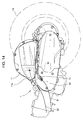
- Fig. 14 shows a side elevation of the power unit 1 and component parts disposed around the power unit 1, taken from the left side.
- the cooling air inlet 71 extends along and behind the edge 78 ( Fig. 1 ) of the body cover. Therefore, entrance of foreign matters into the cooling air inlet 71 can be easily prevented.
- the body cover 13 is provided with pillion footrests 79 ( Fig. 1 ).
- the cooling air duct 50 is disposed in a space covered with a laterally protruding side skirt 80 below the pillion footrest 79. Therefore, cooling air can flow smoothly as indicated by the arrow 81 in Fig.14 through the space covered with the laterally protruding skirt 80 and hence cooling efficiency can be improved.
- the cooling air inlet 71 is disposed in an upper part of a space extending beside the drive pulley 40, the cooling air inlet 71 is separated by a long distance from muddy water and dust flung up by the rear wheel 10 and hence entrance of muddy water and dust through the cooling air inlet 71 can be suppressed and the component parts of the cooling air duct are small. It is advantageous that muddy water that flows along the upper surface of the transmission case 37 holding the V-belt drive continuously variable transmission 18 does not flow into the transmission case 37.
- the air cleaner 11 is disposed above the transmission case 37 such that the inlet 11a of the air cleaner 11 is positioned above an upwardly protruding part of the cooling air duct 50 in which the U-shaped part 74 is formed. Therefore, intake air can smoothly flow along the cooling air duct 50 toward the inlet 11a of the air cleaner 11 as indicated by the arrow 82 and hence the performance of the internal combustion engine 16 can be improved.
Landscapes
- Engineering & Computer Science (AREA)
- Mechanical Engineering (AREA)
- General Engineering & Computer Science (AREA)
- Chemical & Material Sciences (AREA)
- Combustion & Propulsion (AREA)
- Transportation (AREA)
- General Details Of Gearings (AREA)
- Arrangement Of Transmissions (AREA)
Abstract
Description
- In V-belt drive continuously variable transmissions for vehicles, frictional heat is generated by frictional contact between a V-belt and a drive pulley and between the V-belt and a driven pulley. The present invention relates to a cooling air intake structure for taking cooling air into the V-belt drive continuously variable transmission when those component parts need cooling.
- A known air intake structure described in
Patent Literature 1 has an air inlet opening toward the rear of the vehicle. This cooling air intake structure is effective in preventing muddy water and dust coming from the front from entering the cooling air intake structure, but is not necessarily effective in preventing muddy water and dust raised up by the rear wheel from entering the cooling air intake structure. - Patent Literature 1:
JP Utility Model Publication S63-17695 Fig.5 ) - It is an object of the present invention to provide a cooling air intake structure capable of avoiding taking in muddy water and dust coming from both the front and rear sides of a vehicle.
- The present invention has been made to solve the foregoing problem. According to the present invention, there is provided a cooling air intake structure for a V-belt drive continuously variable transmission disposed beside the rear wheel of a small vehicle, characterized in that a cooling air inlet through which cooling air is taken in is formed at a position beside a transmission case and above a cooling fan side opening formed in the transmission case opposite to a drive pulley; and a cooling air passage extending from the cooling air inlet to the side opening is formed in a manner surrounding the side opening.
- In a preferred form of the present invention, the cooling air passage is formed in the shape of an inverted letter U such that cooling air taken in through the cooling air inlet formed at the position in an upper part of a space beside the transmission case flows upward first and then flows downward to the cooling fan side opening of the transmission case.
- In a preferred form of the present invention, the cooling air inlet extends along an edge of a body cover.
- In a preferred form of the present invention, the body cover is provided with pillion footrests, and the cooling air passage is formed in a space covered with the body cover extending below the pillion footrest.
- In a preferred form of the present invention, an air cleaner is disposed above the transmission case such that an inlet of the air cleaner is above a cooling air duct forming the cooling air passage having the shape of an inverted letter U.
- In a preferred form of the present invention, the cooling air passage is formed in the cooling air duct, and the cooling air duct covers the side opening formed in the transmission case and is attached to a flat part of the transmission case beside the drive pulley.
- In a preferred form of the present invention, the cooling air duct is fastened to the transmission case with fastening members arranged on front and rear sides of the side opening formed in the transmission case.
- In a preferred form of the present invention, at least a part of the cooling air inlet is positioned in an area which is beside the drive pulley of the V-belt drive continuously variable transmission and which has a diameter equal to that of the drive pulley.
- In a preferred form of the present invention, cooling air flows in the cooling air duct along the U-shaped passage, and then flows rearward along an L-shaped passage to the cooling fan side opening.
- In a preferred form of the present invention, a vibration isolating member is placed between the cooling air duct and the transmission case.
- According to the present invention, the cooling air inlet can be spaced a long distance apart from muddy water and dust flung up by the rear wheel. The cooling air duct can be formed in a small size. Therefore, entry of muddy water and dust into the cooling air inlet can be suppressed. Further, the cooling air intake structure has the advantage of preventing muddy water flowing along the upper surface of the transmission case from flowing into the transmission case.
- Muddy water and dust can be separated from cooling air by the U-shaped cooling air passage. Therefore, if the cooling air intake structure is provided with a filter, the life of the filter can be extended.
- Flow of foreign matters through the cooling air inlet can be easily prevented by the body cover.
- The cooling air passage is formed in a space covered with a laterally protruding side skirt of the body cover below the pillion footrest. Therefore, cooling air can flow smoothly through the space inside the side skirt to the cooling air inlet.
- Intake air can flow smoothly through the cooling air passage to the inlet of the air cleaner. Consequently, the performance of the internal combustion engine can be improved.
- The cooling air duct is attached to the flat part beside the drive pulley. Therefore, intake noise generated by intake air flowing through the cooling fan side opening formed in the transmission case can be absorbed and noise suppressing effect can be improved.
- The cooling air duct can firmly be attached to the transmission case with the fastening members arranged on the front and rear sides of the side opening.
- Since the cooling air inlet can be spaced a long distance apart from dust flung up by the rear wheel without increasing the size of a front part of the V-belt drive continuously variable transmission, entrance of dust into the transmission can be suppressed.
- Since a part of the cooling air passage continuous with the U-shaped part is bent in the L-shape, the efficiency of separating muddy water and dust from cooling air is improved and hence cleaning load on the filter can be reduced.
- Leakage of cooling air through gaps is prevented and hence noise suppressing effect can further be improved.
-
-
Fig. 1 is a side elevation of amotorcycle 2 relating to a preferred embodiment of the present invention; -
Fig. 2 is a side elevation, partly in section, of apower unit 1 as viewed from the left side; -
Fig. 3 is a sectional view taken on the line III-III inFig. 2 ; -
Fig. 4 is a sectional view of a lefthalf transmission case 37L of a transmission case taken in a horizontal plane; -
Fig. 5 is a side elevation of the lefthalf transmission case 37L of the transmission case as viewed from the left side; -
Fig. 6 is a sectional view of aninner duct member 50A of a cooling air duct taken in a horizontal plane; -
Fig. 7 is a side elevation of theinner duct member 50A of the cooling air duct as viewed from the left side; -
Fig. 8 is a sectional view of anouter duct member 50B of the cooling air duct taken in a horizontal plane; -
Fig. 9 is a side elevation of theouter duct member 50B of the cooling air duct as viewed from the left side, showing the outer surface of the outer duct member; -
Fig. 10 is a side elevation of theouter duct member 50B of the cooling air duct as viewed from the right side, showing the inner surface of the outer duct member; -
Fig. 11 is a sectional view of the assembly of the lefthalf transmission case 37L and thecooling air duct 50 taken in a horizontal plane; -
Fig. 12 is a perspective view of acooling air passage 70 defined by thecooling air duct 50; -
Fig. 13 is a side elevation of atransmission 17 in a state where acooling air duct 50 is attached to the lefthalf transmission case 37L, taken from the left side; and -
Fig. 14 is a side elevation of thepower unit 1 and component parts disposed around the power unit, taken from the left side. - 11 ... Air cleaner, 11a ... Inlet of the air cleaner, 13 ... Body cover, 18 ... V-belt drive continuously variable transmission, 37 ... Transmission case, 37L ... Left half transmission case, 37R ... Right half transmission case, 40 ... Drive pulley, 50 ... Cooling air duct, 50A ... Inner duct member of the cooling air duct, 50B ... Outer duct member of the cooling air duct, 51 ...Cooling fan, 52 ... Side opening formed in the transmission case opposite to a cooling fan, 56 ... Flat part of the transmission case beside a drive pulley, 66 ... Round O-ring (vibration isolating member), 67 ... Guide wall defining a cooling air passage, 68 ... O-ring, 70 ... Cooling air passage, 71 ... Cooling air inlet, 74 ... U-shaped part, 75 ... L-shaped part, 76 ... Fastening member, 77 ... Space of a diameter equal to the diameter of the
drive pulley -
Fig. 1 is a side elevation of amotorcycle 2 provided with apower unit 1 relating to a preferred embodiment of the present invention. Themotorcycle 2 has a body frame formed by assembling a head pipe, a main frame extending obliquely downward toward the rear from the head pipe, right and left rear frames connected to the rear end of the main frame and extending obliquely upward toward the rear, and some frames. A front wheel 4 is rotatably supported on the lower end of afront fork 3 which is rotatably supported on the head pipe. Ahandlebar 5 is connected to an upper end part of thefront fork 3. - The
power unit 1 is suspended from the rear frame by connecting a hanger 6 (Fig. 2 ) formed integrally with a front part of thepower unit 1 to a bracket fixed to the rear frame by asupport shaft 7. Arear cushion 8 is extended between a bracket 14 (Fig. 2 ) formed on a rear end part of thepower unit 1, and a bracket formed on a rear end part of the rear frame. Thus, thepower unit 1 is suspended for swinging with the axis of its cylinder slightly inclined upward toward the front. Arear wheel 10 is mounted on a rear axle 9 (Fig. 3 ) extending to the right from a rear part of thepower unit 1. Therear axle 9 is driven by thepower unit 1. - An
air cleaner 11 is disposed above thepower unit 1. Abody cover 13, made of a synthetic resin and consisting of a plurality of parts, is attached to the body frame so as to cover thepower unit 1 and other component parts. -
Fig. 2 is a vertical sectional view of thepower unit 1 as viewed from the left side. Terms modified by front, rear, right and left, are used for indicating positions, sides and parts on the front, rear, right and left sides, respectively, of the vehicle provided with the power unit. As shown inFig. 2 , thepower unit 1 includes aninternal combustion engine 16 and atransmission 17 extending toward the rear from the left side of theinternal combustion engine 16. Thetransmission 17 includes a V-belt drive continuouslyvariable transmission 18 and areduction gear 19. - The
engine 16 is a rocker arm type, water-cooled, four-stroke cycle, overhead valve, single-cylinder internal combustion engine. Anintake pipe 20 has one end connected to an intake port formed in an upper part of acylinder head 25 and the other end connected to athrottle body 21. The air cleaner 11 (Fig. 1 ) is connected to the inlet end of thethrottle body 21. Afuel injection valve 22 is connected to theintake pipe 20. A gearcase breather hose 39 is extended from an upper part of agear case 38 and is connected to the intake chamber of theair cleaner 11. Aspeed sensor 49 is connected to an upper part of thegear case 38. Thespeed sensor 49 senses the tip speed of a gear 48 (Fig. 3 ) mounted on therear axle 9 to determine a vehicle speed. -
Fig. 3 shows a sectional view taken on the line III-III inFig. 2 . Referring toFig. 3 , the engine body of theinternal combustion engine 16 is formed of acrankcase 23, acylinder block 24 connected to the front end of thecrankcase 23, acylinder head 25 connected to the front end of thecylinder block 24, and acylinder head cover 26 put on thecylinder head 25. Thecrankcase 23 is formed by joining together a left half crankcase 23L and aright half crankcase 23R. - A
crankshaft 27 is supported for rotation inball bearings crankcase 23. Apiston 29 is slidably fitted in a cylinder bore 30 formed in thecylinder block 24. Thepiston 29 is connected to thecrankpin 32 of thecrankshaft 27 by a connectingrod 31. Thepiston 29 reciprocates to drive thecrankshaft 27 for rotation. Acombustion chamber 33 is formed in the bottom surface of thecylinder head 25 opposite to the top surface of thepiston 29. Aspark plug 34 is attached to thecylinder head 25 such that the axis thereof is tilted to the left with respect to the center axis of the cylinder bore 30. - The
transmission 17 is made up of the V-belt drive continuouslyvariable transmission 18 and thereduction gear 19. The V-belt drive continuouslyvariable transmission 18 is covered with atransmission case 37. Thetransmission case 37 has a righthalf transmission case 37R and a lefthalf transmission case 37L. The righthalf transmission case 37R is fixedly connected to the left half crankcase 23L. The righthalf transmission case 37R and the lefthalf transmission case 37L are fastened together with bolts. Thereduction gear 19 is covered with a rear part of the righthalf transmission case 37R and thegear case 38. Thegear case 38 is fastened to the righthalf transmission case 37R with bolts. - The
crankshaft 27 serves as the drive shaft of the V-belt drive continuouslyvariable transmission 18. Adrive pulley 40 included in the V-belt drive continuouslyvariable transmission 18 is mounted on a left part of thecrankshaft 27. A drivenshaft 41 is supported for rotation inbearings half transmission case 37L, the righthalf transmission case 37R and thegear case 38. A drivenpulley 44 is interlocked with the drivenshaft 41 by a centrifugal clutch 43 mounted on the drivenshaft 41. An endless V-belt 45 is extended between thedrive pulley 40 and the drivenpulley 44. - The
drive pulley 40 includes a fixedhalf part 40A, a movablehalf part 40B,weight rollers 40C and aramp plate 40D. The drivenpulley 44 includes a fixedhalf part 44A, a movablehalf part 44B, arotating sleeve 44C and acoil spring 44D. The centrifugal clutch 43 includes an outerclutch member 43A and an innerclutch member 43B. The outerclutch member 43A is interlocked with the drivenshaft 41. The innerclutch member 43B is connected to therotating sleeve 44C. - As the rotational speed of the
crankshaft 27 increases, theweight rollers 40C placed in a space between the movablehalf part 40B and theramp plate 40D are moved radially outward by centrifugal force and the movablehalf part 40B is pushed by theweight rollers 40C toward the fixedhalf part 40A to increase the working pitch diameter of thedrive pulley 40 and tensile stress induced in the V-belt 45 increases. Consequently, the movablehalf part 44B of the drivenpulley 44 is moved against the resilience of thecoil spring 44D, the distance between the fixedhalf part 44A and the movablehalf part 44B increases and the working pitch diameter of the drivenpulley 44 is diminished. The rotational speed of the drivenpulley 44 increases when the ratio of the working pitch diameter of thedrive pulley 40 to that of the drivenpulley 44 is thus increased. Upon the increase of the rotational speed of the drivenpulley 44 beyond a predetermined rotational speed, the rotation of the drivenpulley 44 is transmitted through therotating sleeve 44C to the innerclutch member 43B of the centrifugal clutch 43, the centrifugal clutch 43 is engaged and the rotation of the drivenpulley 44 is transmitted to the drivenshaft 41. - The driven
shaft 41 serves also as the input shaft of thereduction gear 19. Adrive pinion 41a is formed integrally with the drivenshaft 41. Therear axle 9 united with therear wheel 10 is supported for rotation on the righthalf transmission case 37R and thegear case 38. Anintermediate shaft 46 disposed between the drivenshaft 41 and therear axle 9 is supported for rotation on the righthalf transmission case 37R and thegear case 38. Anintermediate gear 47 is fixedly mounted on theintermediate shaft 46 and is engaged with thedrive pinion 41a. Anintermediate pinion 46a is formed integrally with theintermediate shaft 46. Arear axle gear 48 is fixedly mounted on therear axle 9 and is engaged with theintermediate pinion 46a. The torque of the drivenshaft 41 is transmitted through thedrive pinion 41a, theintermediate gear 47, theintermediate shaft 46, theintermediate pinion 46a and therear axle gear 48 to therear axle 9. The rotational speed of therear axle 9 is far lower than that of the drivenshaft 41 to drive therear wheel 10 on therear axle 9 at a reduced rotational speed. - Referring to
Fig. 3 , frictional heat is generated by frictional contact between the V-belt 45 and thedrive pulley 44 and between the V-belt 45 and the drivenpulley 44. The continuouslyvariable transmission 18 is heated to high temperature by the frictional heat. Acentrifugal cooling fan 51 is formed integrally with the fixedhalf part 40A of thedrive pulley 40 on the left surface, namely, the back surface, of the fixedhalf part 40A. The coolingfan 51 sucks cooling air through the coolingair duct 50 and aside opening 52 formed in the lefthalf transmission case 37L opposite to the coolingfan 51 to cool the continuouslyvariable transmission 18. Air used for cooling the V-belt drive continuouslyvariable transmission 18 is discharged to the outside through an outlet opening 53 (Fig. 2 ) formed in a rear part of thetransmission case 37. The coolingair duct 50 is placed at a position corresponding to a front part of the lefthalf transmission case 37L. The coolingair duct 50 has aninner duct member 50A and anouter duct member 50B. -
Fig. 4 shows a sectional view of the lefthalf transmission case 37L taken in a horizontal plane andFig. 5 shows a side elevation of the lefthalf transmission case 37L taken from the left side in the direction of the arrow V inFig. 4 . A front part of the lefthalf transmission case 37L corresponding to the drivepulley 40 has aflat part 56. The coolingair duct 50 is attached to theflat part 56. Theside opening 52, namely, a cooling air inlet, is formed in a central part of theflat part 56. Bolt holes 57 for bolts for fastening together the righthalf transmission case 37R and the lefthalf transmission case 37L are formed in a peripheral part and a middle part of the lefthalf transmission case 37L. As shown inFig. 3 ,bolts 58 are passed through the bolt holes 57 in the middle part and a rear part to fasten the lefthalf transmission case 37L to the righthalf transmission case 37R. Three internally threadedholes 59 are formed in a front part of the lefthalf transmission case 37L for bolts for fastening the coolingair duct 50 to the lefthalf transmission case 37L. -
Fig. 6 shows an enlarged sectional view of theinner duct member 50A of the coolingair duct 50 taken in a horizontal plane andFig. 7 shows a side elevation of theinner duct member 50A of the coolingair duct 50 as viewed from the left side in the direction of the arrow VII.Fig. 6 is a sectional view taken on the line VI-VI inFig. 7 . A coolingair outlet 62 is formed in a central part of theinner duct member 50A of the coolingair duct 50, which is opposite to theside opening 52 of the lefthalf transmission case 37L. Acircular sealing groove 63 is formed in the inner surface of theinner duct member 50A facing the lefthalf transmission case 37L, so as to correspond to a part of the lefthalf transmission case 37L surrounding theside opening 52 opposite the cooling fan. An O-ring is fitted in thecircular sealing groove 63. A sealinggroove 64 is formed in the left surface, namely, the outer surface, of theinner duct member 50A so as to extend along a part of the peripheral part and around a central part of the left surface. An edge part of theguide wall 67 of theouter duct member 50B of the coolingair duct 50 is fitted in the sealinggroove 64. Theinner duct member 50A is provided with threebolt holes 65 for bolts for fastening the coolingair duct 50. -
Fig. 8 shows an enlarged sectional view of theouter duct member 50B of the coolingair duct 50 taken in a horizontal plane,Fig. 9 shows a side elevation of theouter duct member 50B as viewed from the left side in the direction of the arrow IX inFig. 8 , showing the outer surface of theouter duct member 50B, andFig. 10 is a side elevation of theouter duct member 50B as viewed from the right side in the direction of the arrow X inFig. 8 , showing the right surface, namely, the inner surface, of theouter duct member 50B.Fig. 8 is a sectional view taken on the line VIII-VIII inFig. 9 . As shown inFig. 8 , theouter duct member 50B is provided on its inner surface with theguide wall 67. The edge part of theguide wall 67 is fitted in the sealinggroove 64 of theinner duct ember 50A provided with an O-ring 68 (Fig. 11 ). The O-ring 68 seals the joint of the edge part of theguide wall 67 and the surface of the sealinggroove 64 to prevent air leakage. - As shown in
Fig. 9 , a coolingair inlet 71 provided withguide fins 72 is formed in an upper part of theouter duct member 50B. Theguide fins 72 define coolingair inlet openings 71a. Theouter duct member 50B is provided with threebolt holes 73 for bolts for fastening the coolingair duct 50. - As shown in
Fig. 10 , theguide wall 67 is erected integrally with theouter duct member 50B. Theguide wall 67 is formed along a part of the periphery, and around a central part, of theouter duct member 50B. Cooling air taken in through the coolingair inlet 71 flows through a passage formed between a firstfront portion 67a of theguide wall 67 in a front part of the coolingair duct 50 and a secondfront portion 67b on the front side of the coolingair inlet 71 to the cooling air outlet 62 (Fig. 7 ). The edge part of theguide wall 67 including theportions groove 64 shown inFig. 7 . Aguide wall 69 is formed behind the coolingair inlet 71. Theguide wall 69 and the secondfront portion 67b of theguide wall 67 guide cooling air taken in through the coolingair inlet 71. As shown inFig. 7 , any sealing groove for receiving theguide wall 69 is not formed. Therefore, a small gap is formed between the edge of theguide wall 69 and the inner surface of theinner duct member 50A of the coolingair duct 50. Rain water leaking in through the coolingair inlet 71 is drained downward through the gap. -
Fig. 11 shows a sectional view, taken in a horizontal plane, of the assembly of the lefthalf transmission case 37L of the transmission case and the coolingair duct 50 including theinner duct member 50A and theouter duct member 50B. The coolingair duct 50 covers theside opening 52 of thetransmission case 37 beside the coolingfan 51, is attached to theflat part 56 of thetransmission case 37 opposite thedrive pulley 40. The coolingair duct 50 defines a coolingair passage 70. The coolingair duct 50 is attached to theflat part 56 beside thedrive pulley 40. Therefore, intake noise generated by intake air flowing through theside opening 52 formed in thetransmission case 37 opposite to the cooling fan can be absorbed and noise suppressing effect can be improved. An O-ring 66 is placed in the joint of the lefthalf transmission case 37L and theinner duct member 50A and the O-ring 68 is placed in the joint of theinner duct member 50A and theouter duct member 50B to seal the joints. Noise leakage can be prevented by the sealing effect of the O-rings -
Fig. 12 is a perspective view of the coolingair passage 70 defined by the coolingair duct 50. Cooling air flows through the coolingair inlet 71 opening into an upper part of a space beside thedrive pulley 40 into the coolingair duct 50, and then flows upward along the arrow indicated by a broken line. The flow of cooling air is inverted by aU-shaped part 74 and cooling air flows downward. Then, cooling air flows along an L-shapedpart 75 toward a central part of the coolingair duct 50 and flows through the cooling air outlet 62 (Fig. 7 ) of theinner duct member 50A and the side opening 50 (Fig. 5 ) of the lefthalf transmission case 37L beside the coolingfan 51 into thetransmission case 37. - Muddy water and dust can be separated from cooling air by inverting the flow of cooling air by the
U-shaped part 74. Therefore, if a filter is used, the life of the filter can be extended. The L-shapedpart 75 connected to theU-shaped part 74 can enhance the efficiency of separating muddy water and dust from cooling air and reduce cleaning load on the filter. -
Fig. 13 is a side elevation, taken from the left side, of thepower unit 1 in a state where the coolingair duct 50 is attached to the lefthalf transmission case 37L. The coolingair duct 50 is fastened to thetransmission case 37 with threefastening members 76 arranged around theside opening 52 beside the coolingfan 51. Therefore, the coolingair duct 50 can be firmly attached to thetransmission case 37 with the threefastening members 76 arranged at three positions around theside opening 52 beside the cooling fan. - At least part of the cooling air inlet extends in an
area 77 extending beside thedrive pulley 40 of the V-belt drive continuouslyvariable transmission 18 and having a diameter equal to that of thedrive pulley 40. Since the cooling air inlet can be spaced apart from dust flung up by therear wheel 10 without increasing the size of a front part of the V-belt drive continuouslyvariable transmission 18, flow of dust into the transmission can be suppressed. -
Fig. 14 shows a side elevation of thepower unit 1 and component parts disposed around thepower unit 1, taken from the left side. The coolingair inlet 71 extends along and behind the edge 78 (Fig. 1 ) of the body cover. Therefore, entrance of foreign matters into the coolingair inlet 71 can be easily prevented. The body cover 13 is provided with pillion footrests 79 (Fig. 1 ). The coolingair duct 50 is disposed in a space covered with a laterally protrudingside skirt 80 below thepillion footrest 79. Therefore, cooling air can flow smoothly as indicated by thearrow 81 inFig.14 through the space covered with the laterally protrudingskirt 80 and hence cooling efficiency can be improved. Since the coolingair inlet 71 is disposed in an upper part of a space extending beside thedrive pulley 40, the coolingair inlet 71 is separated by a long distance from muddy water and dust flung up by therear wheel 10 and hence entrance of muddy water and dust through the coolingair inlet 71 can be suppressed and the component parts of the cooling air duct are small. It is advantageous that muddy water that flows along the upper surface of thetransmission case 37 holding the V-belt drive continuouslyvariable transmission 18 does not flow into thetransmission case 37. - The
air cleaner 11 is disposed above thetransmission case 37 such that theinlet 11a of theair cleaner 11 is positioned above an upwardly protruding part of the coolingair duct 50 in which theU-shaped part 74 is formed. Therefore, intake air can smoothly flow along the coolingair duct 50 toward theinlet 11a of theair cleaner 11 as indicated by thearrow 82 and hence the performance of theinternal combustion engine 16 can be improved. - The embodiment described above has the following advantages.
- (1) The cooling
air passage 70 through which cooling air flows into the V-belt drive continuously variable transmission extends from the coolingair inlet 71 above the space beside thedrive pulley 40 to theside opening 52 formed in thetransmission case 37 beside the cooling fan. Therefore, the coolingair inlet 71 is at a long distance from muddy water and dust flung up by therear wheel 10 and hence entrance of muddy water and dust into the coolingair inlet 71 can be suppressed. Further, the component members of the cooling air duct can be of small size. It is advantageous that muddy water that flows along the upper surface of thetransmission case 37 holding the V-belt drive continuouslyvariable transmission 18 does not flow into thetransmission case 37 - (2) The cooling
air passage 70 is formed such that cooling air is taken in through the coolingair inlet 71 positioned above the space beside thetransmission case 37, and flows along theU-shaped part 74 having the shape of the inverted letter U into theside opening 52 formed in thetransmission case 37 beside the cooling fan. Thus muddy water and dust can be separated from cooling air by theU-shaped part 74. Therefore, if a filter is used, the life of the filter can be extended. - (3) The cooling
air inlet 71 extends along and behind theedge 78 of the body cover. Therefore, entrance of foreign matters into the coolingair inlet 71 can be easily prevented. - (4) The cooling
air duct 50 is disposed in a space covered with a laterally protrudingside skirt 80 below thepillion footrest 79. Therefore, cooling air can flow smoothly as indicated by thearrow 81 through the space covered with the laterally protrudingskirt 80 and hence cooling efficiency can be improved. - (5) The
air cleaner 11 is disposed above thetransmission case 37 such that theinlet 11a of theair cleaner 11 is positioned above the coolingair duct 50. Therefore, intake air can smoothly flow along the coolingair duct 50 toward theinlet 11a of theair cleaner 11 as indicated by thearrow 82 and hence the performance of theinternal combustion engine 16 can be improved. - (6) The cooling
air passage 70 is defined by the coolingair duct 50 covering theside opening 52 of thetransmission case 37 beside the cooling fan of thetransmission case 37. Therefore, intake noise generated by intake air flowing through theside opening 52 formed in thetransmission case 37 opposite to the cooling fan can be absorbed and noise suppressing effect can be improved. - (7) The cooling
air duct 50 is fastened to thetransmission case 37 with the threefastening members 76 arranged around theside opening 52 beside the cooling fan. Therefore, the coolingair duct 50 can be firmly attached to the transmission case. - (8) At least part of the cooling
air inlet 71 extends in anarea 77 extending beside thedrive pulley 40 of the V-belt drive continuouslyvariable transmission 18 and having a diameter equal to that of thedrive pulley 40. Therefore, the enlargement of the front part of the V-belt drive continuouslyvariable transmission 18 can be avoided, the coolingair inlet 71 can be spaced a long distance apart from dust raised up by therear wheel 10 and the entrance of dust into the V-belt drive continuouslyvariable transmission 18 can be suppressed. - (9) Cooling air flows along the U-shaped
cooling air passage 74 and the L-shapedcooling air passage 75 connected to the U-shapedcooling air passage 74 in the coolingair duct 50 to theside opening 52 beside the cooling fan. Therefore, the efficiency of separating muddy water and dust from cooling air is enhanced and, if a filter is used, cleaning load on the filter can be reduced. - (10) The O-
ring 66 is placed in the joint of the coolingair duct 50 and thetransmission case 37. Therefore, Noise leakage through gaps can be prevented and noise suppressing effect can be improved.
Claims (10)
- A cooling air intake structure for a V-belt drive continuously variable transmission disposed beside the rear wheel of a small vehicle, wherein a cooling air inlet through which cooling air is taken in is formed at a position beside a transmission case and above a cooling fan side opening formed in the transmission case opposite to a drive pulley; and a cooling air passage extending from the cooling air inlet to the side opening is formed in a manner surrounding the side opening.
- The cooling air intake structure according to claim 1, wherein the cooling air passage is formed in the shape of an inverted letter U such that cooling air taken in through the cooling air inlet formed at the position in an upper part of a space beside the transmission case flows upward first and then flows downward to the cooling fan side opening of the transmission case.
- The cooling air intake structure according to claim 1 or 2, wherein the cooling air inlet extends along an edge of a body cover.
- The cooling air intake structure according to claim 3, wherein the body cover is provided with pillion footrests, and the cooling air passage is formed in a space covered with the body cover extending below the pillion footrest.
- The cooling air intake structure according to claim 2, wherein an air cleaner is disposed above the transmission case such that an inlet of the air cleaner is above a cooling air duct forming the cooling air passage having the shape of an inverted letter U.
- The cooling air intake structure according to claim 5, wherein the cooling air passage is formed in the cooling air duct, which covers the side opening formed in the transmission case and is attached to a part of the transmission case beside the drive pulley.
- The cooling air intake structure according to claim 6, wherein the cooling air duct is fastened to the transmission case with fastening members arranged on front and rear sides of the side opening formed in the transmission case.
- The cooling air intake structure according to claim 2, wherein at least a part of the cooling air inlet is located in an area which is beside the drive pulley of the V-belt drive continuously variable transmission and which has a diameter equal to that of the drive pulley.
- The cooling air intake structure according to claim 8, wherein cooling air flows in the cooling air duct along the U-shaped passage, and then flows rearward along an L-shaped passage to the cooling fan side opening.
- The cooling air intake structure according to any one of claims 5 to 9, wherein a vibration isolating member is placed between the cooling air duct and the transmission case.
Applications Claiming Priority (1)
| Application Number | Priority Date | Filing Date | Title |
|---|---|---|---|
| PCT/JP2009/065404 WO2011027445A1 (en) | 2009-09-03 | 2009-09-03 | Cooling air intake structure for v-belt type stepless transmission |
Publications (3)
| Publication Number | Publication Date |
|---|---|
| EP2474435A1 true EP2474435A1 (en) | 2012-07-11 |
| EP2474435A4 EP2474435A4 (en) | 2013-03-27 |
| EP2474435B1 EP2474435B1 (en) | 2015-09-16 |
Family
ID=43649007
Family Applications (1)
| Application Number | Title | Priority Date | Filing Date |
|---|---|---|---|
| EP09848976.8A Active EP2474435B1 (en) | 2009-09-03 | 2009-09-03 | Cooling air intake structure for v-belt type stepless transmission |
Country Status (10)
| Country | Link |
|---|---|
| US (1) | US8840496B2 (en) |
| EP (1) | EP2474435B1 (en) |
| JP (1) | JP5443500B2 (en) |
| KR (1) | KR101387673B1 (en) |
| CN (1) | CN102483146B (en) |
| AU (1) | AU2009352070B2 (en) |
| ES (1) | ES2556329T3 (en) |
| IN (1) | IN2012DN01852A (en) |
| TW (1) | TWI409397B (en) |
| WO (1) | WO2011027445A1 (en) |
Cited By (4)
| Publication number | Priority date | Publication date | Assignee | Title |
|---|---|---|---|---|
| EP2827024A1 (en) * | 2013-07-18 | 2015-01-21 | Kwang Yang Motor Co., Ltd. | Cooling airflow guide structure of vehicle transmission box |
| WO2016166167A1 (en) | 2015-04-16 | 2016-10-20 | Piaggio & C. S.P.A. | Cover structure for the transmission of a motorcycle |
| CN107076292A (en) * | 2014-07-22 | 2017-08-18 | 铃木株式会社 | The cooling structure of buncher |
| CN108626021A (en) * | 2017-03-21 | 2018-10-09 | Tvs电机股份有限公司 | A cooling system for an internal combustion engine |
Families Citing this family (36)
| Publication number | Priority date | Publication date | Assignee | Title |
|---|---|---|---|---|
| JP5819126B2 (en) * | 2011-07-23 | 2015-11-18 | 本田技研工業株式会社 | Power unit for small vehicles |
| US8911312B2 (en) * | 2011-10-06 | 2014-12-16 | Kawasaki Jukogyo Kabushiki Kaisha | Belt type continuously variable transmission |
| US8834307B2 (en) | 2011-10-06 | 2014-09-16 | Kawasaki Jukogyo Kabushiki Kaisha | Belt type continuously variable transmission |
| US8556015B2 (en) | 2011-10-07 | 2013-10-15 | Kawasaki Jukogyo Kabushiki Kaisha | Utility vehicle |
| US8596406B2 (en) * | 2011-10-07 | 2013-12-03 | Kawasaki Jukogyo Kabushiki Kaisha | Utility vehicle |
| JP5929561B2 (en) * | 2012-06-29 | 2016-06-08 | 株式会社ジェイテクト | Electric rotating machine and manufacturing method thereof |
| US9103428B2 (en) * | 2013-03-15 | 2015-08-11 | Kawasaki Jukogyo Kabushiki Kaisha | Structure for coupling V-belt type continuously variable transmission with engine |
| US9366331B2 (en) * | 2013-07-22 | 2016-06-14 | Arctic Cat Inc. | Transmission cover with improved airflow |
| US9528595B2 (en) * | 2014-04-24 | 2016-12-27 | Kawasaki Jukogyo Kabushiki Kaisha | V-belt type continuously variable transmission |
| US9453573B2 (en) * | 2014-06-30 | 2016-09-27 | Brp-Powertrain Gmbh & Co. Kg | Continuously variable transmission assembly for a vehicle |
| US10648554B2 (en) * | 2014-09-02 | 2020-05-12 | Polaris Industries Inc. | Continuously variable transmission |
| USD771146S1 (en) * | 2015-02-26 | 2016-11-08 | Caterpillar Inc. | Belt cover |
| JP6512967B2 (en) * | 2015-07-02 | 2019-05-15 | 株式会社クボタ | Work vehicle |
| EP3339076B1 (en) * | 2015-08-21 | 2020-05-20 | Honda Motor Co., Ltd. | Power unit for saddle-type vehicle |
| ITUB20155584A1 (en) * | 2015-11-13 | 2017-05-13 | Piaggio & C Spa | Engine cooling system of a motor vehicle |
| US9863523B2 (en) * | 2016-03-21 | 2018-01-09 | Textron Innovations Inc. | Continuously variable transmission |
| US10197149B2 (en) * | 2016-03-23 | 2019-02-05 | Kawasaki Jukogyo Kabushiki Kaisha | V-belt type continuously variable transmission |
| KR20170115694A (en) * | 2016-04-08 | 2017-10-18 | 현대자동차주식회사 | Timing belt cover assembly for vehicle |
| USD809019S1 (en) * | 2016-12-08 | 2018-01-30 | Gary Don Armstrong | Belt guard |
| US10697532B2 (en) * | 2016-12-22 | 2020-06-30 | Polaris Industries Inc. | Housing for a transmission |
| US10443704B2 (en) | 2017-02-28 | 2019-10-15 | Textron Innovations Inc. | Continuously variable transmission cooling |
| US10563751B2 (en) | 2017-04-19 | 2020-02-18 | Excel Industries, Inc. | Cooling apparatus for continuously variable transmissions |
| US11124271B2 (en) * | 2017-12-22 | 2021-09-21 | Bombardier Recreational Products Inc. | Snowmobile having an air-cooled continuously variable transmission |
| JP6670335B2 (en) * | 2018-03-16 | 2020-03-18 | 本田技研工業株式会社 | Belt-type continuously variable transmission for straddle-type vehicles |
| MX2020009417A (en) | 2018-03-19 | 2020-10-05 | Polaris Inc | CONTINUOUSLY VARIABLE TRANSMISSION. |
| WO2019182951A1 (en) | 2018-03-19 | 2019-09-26 | Polaris Industries Inc. | Electronic cvt with friction clutch |
| JP2020131839A (en) * | 2019-02-15 | 2020-08-31 | 本田技研工業株式会社 | Vehicle intake duct structure |
| JP6893524B2 (en) * | 2019-03-18 | 2021-06-23 | 本田技研工業株式会社 | Continuously variable transmission |
| JP7232090B2 (en) * | 2019-03-19 | 2023-03-02 | 株式会社Subaru | vehicle |
| US11795895B2 (en) * | 2020-04-04 | 2023-10-24 | Kawasaki Motors, Ltd. | Air intake structure for engine |
| US12504070B2 (en) | 2021-01-29 | 2025-12-23 | Polaris Industries Inc. | Electronically-controlled continuously variable transmission for a utility vehicle |
| EP4140792A1 (en) * | 2021-08-30 | 2023-03-01 | TVS Motor Company Limited | Air inlet device for transmission system of a vehicle |
| US11913537B2 (en) * | 2022-01-18 | 2024-02-27 | Kris Werth, Inc. | CVT belt cooling system |
| CN114607758A (en) * | 2022-03-08 | 2022-06-10 | 重庆隆鑫新能源科技有限公司 | Cooling air guide structure of V-belt type electrodeless engine and engine |
| US11739824B1 (en) * | 2022-04-25 | 2023-08-29 | Kawasaki Motors, Ltd. | Waterproof case and continuously variable transmission |
| TWI857486B (en) * | 2023-02-09 | 2024-10-01 | 三陽工業股份有限公司 | Engine transmission case |
Family Cites Families (30)
| Publication number | Priority date | Publication date | Assignee | Title |
|---|---|---|---|---|
| US2205975A (en) * | 1934-02-19 | 1940-06-25 | Us Electrical Motors Inc | Ventilated variable speed power unit |
| US2189294A (en) * | 1936-07-27 | 1940-02-06 | Us Electrical Motors Inc | Variable speed transmission device |
| US2315317A (en) * | 1939-08-17 | 1943-03-30 | Renold & Coventry Chain Co | Casing for chain belt and like transmissions |
| JPS59195018U (en) * | 1983-06-14 | 1984-12-25 | 本田技研工業株式会社 | Cooling system for transmission system in motorcycles |
| US4671782A (en) | 1984-05-28 | 1987-06-09 | Honda Giken Kogyo Kabushiki Kaisha | Cooler for a belt type stageless transmission |
| US4671781A (en) * | 1984-08-03 | 1987-06-09 | Honda Giken Kogyo Kabushiki Kaisha | Cooling system for a belt type transmission |
| JPS61193890A (en) | 1985-02-23 | 1986-08-28 | Nec Corp | Laser marker |
| JPS61193890U (en) * | 1985-05-28 | 1986-12-02 | ||
| US4697665A (en) * | 1985-06-18 | 1987-10-06 | Polaris Industries, Inc. | Recreational vehicle with air cooled transmission |
| JPH06272750A (en) * | 1993-03-19 | 1994-09-27 | Yamaha Motor Co Ltd | Cooling device for v-belt transmission device of vehicle |
| JPH06317695A (en) | 1993-05-07 | 1994-11-15 | Hitachi Ltd | Mixed flow piping structure |
| JP2000120847A (en) * | 1998-10-15 | 2000-04-28 | Suzuki Motor Corp | Cooling device for vehicle power unit |
| JP3709973B2 (en) * | 2000-03-31 | 2005-10-26 | 本田技研工業株式会社 | Belt-type transmission |
| JP3709974B2 (en) * | 2000-04-06 | 2005-10-26 | 本田技研工業株式会社 | V-belt transmission |
| JP3916376B2 (en) * | 2000-06-15 | 2007-05-16 | 本田技研工業株式会社 | Breather structure of internal combustion engine for vehicle |
| JP2002021989A (en) * | 2000-07-05 | 2002-01-23 | Yamaha Motor Co Ltd | Motorcycle engine cooling system |
| JP3696508B2 (en) * | 2000-12-28 | 2005-09-21 | 本田技研工業株式会社 | Radiator device for vehicle |
| JP4067769B2 (en) * | 2001-01-15 | 2008-03-26 | 本田技研工業株式会社 | Belt change time notification device for belt type automatic transmission |
| JP4134596B2 (en) * | 2002-05-17 | 2008-08-20 | スズキ株式会社 | Cooling structure of belt type automatic transmission for scooter type motorcycle |
| JP4700260B2 (en) * | 2003-04-18 | 2011-06-15 | 富士重工業株式会社 | Continuously variable transmission |
| US7237638B2 (en) * | 2003-09-30 | 2007-07-03 | Honda Motor Co., Ltd. | V-belt type continuously variable transmission |
| JP4627425B2 (en) * | 2004-09-29 | 2011-02-09 | 本田技研工業株式会社 | Shift control device for continuously variable transmission |
| JP2007062715A (en) * | 2005-08-01 | 2007-03-15 | Yamaha Motor Co Ltd | Saddle riding vehicle |
| US20070219030A1 (en) * | 2006-03-16 | 2007-09-20 | Kwang Yang Motor Co., Ltd. | Cooling mechanism for belt-based speed-change system of engine |
| JP4887200B2 (en) * | 2006-08-08 | 2012-02-29 | 本田技研工業株式会社 | Engine with decompression device |
| JP4963976B2 (en) * | 2007-01-26 | 2012-06-27 | ヤマハ発動機株式会社 | Saddle-type vehicle equipped with a belt-type continuously variable transmission having a resin block belt |
| JP2008185054A (en) * | 2007-01-26 | 2008-08-14 | Yamaha Motor Co Ltd | Belt-type continuously variable transmission having a resin block belt and a motorcycle including the same |
| JP2008201230A (en) * | 2007-02-19 | 2008-09-04 | Yamaha Motor Co Ltd | Saddle riding vehicle |
| JP4999582B2 (en) * | 2007-07-12 | 2012-08-15 | 本田技研工業株式会社 | Transmission case cooling structure for motorcycle power unit |
| JP5203739B2 (en) * | 2008-02-14 | 2013-06-05 | 本田技研工業株式会社 | Cooling structure for belt type continuously variable transmission |
-
2009
- 2009-09-03 CN CN200980161229.0A patent/CN102483146B/en active Active
- 2009-09-03 AU AU2009352070A patent/AU2009352070B2/en not_active Ceased
- 2009-09-03 US US13/393,016 patent/US8840496B2/en not_active Expired - Fee Related
- 2009-09-03 KR KR1020127007321A patent/KR101387673B1/en not_active Expired - Fee Related
- 2009-09-03 WO PCT/JP2009/065404 patent/WO2011027445A1/en not_active Ceased
- 2009-09-03 EP EP09848976.8A patent/EP2474435B1/en active Active
- 2009-09-03 JP JP2011529735A patent/JP5443500B2/en not_active Expired - Fee Related
- 2009-09-03 ES ES09848976.8T patent/ES2556329T3/en active Active
- 2009-09-03 IN IN1852DEN2012 patent/IN2012DN01852A/en unknown
-
2010
- 2010-08-30 TW TW099129065A patent/TWI409397B/en not_active IP Right Cessation
Cited By (8)
| Publication number | Priority date | Publication date | Assignee | Title |
|---|---|---|---|---|
| EP2827024A1 (en) * | 2013-07-18 | 2015-01-21 | Kwang Yang Motor Co., Ltd. | Cooling airflow guide structure of vehicle transmission box |
| CN107076292A (en) * | 2014-07-22 | 2017-08-18 | 铃木株式会社 | The cooling structure of buncher |
| CN107076292B (en) * | 2014-07-22 | 2019-06-18 | 铃木株式会社 | Cooling structure of continuously variable transmission |
| WO2016166167A1 (en) | 2015-04-16 | 2016-10-20 | Piaggio & C. S.P.A. | Cover structure for the transmission of a motorcycle |
| US10502310B2 (en) | 2015-04-16 | 2019-12-10 | Piaggio & C. S.P.A. | Cover structure for the transmission of a motorcycle |
| CN108626021A (en) * | 2017-03-21 | 2018-10-09 | Tvs电机股份有限公司 | A cooling system for an internal combustion engine |
| EP3392529A3 (en) * | 2017-03-21 | 2019-01-23 | TVS Motor Company Limited | A cooling system for an internal combustion engine |
| CN108626021B (en) * | 2017-03-21 | 2022-04-01 | Tvs电机股份有限公司 | Saddle type vehicle |
Also Published As
| Publication number | Publication date |
|---|---|
| TW201113455A (en) | 2011-04-16 |
| EP2474435B1 (en) | 2015-09-16 |
| US8840496B2 (en) | 2014-09-23 |
| CN102483146B (en) | 2015-07-15 |
| EP2474435A4 (en) | 2013-03-27 |
| CN102483146A (en) | 2012-05-30 |
| ES2556329T3 (en) | 2016-01-15 |
| IN2012DN01852A (en) | 2015-08-21 |
| KR20120062808A (en) | 2012-06-14 |
| AU2009352070B2 (en) | 2013-12-05 |
| JPWO2011027445A1 (en) | 2013-01-31 |
| KR101387673B1 (en) | 2014-04-22 |
| US20120289370A1 (en) | 2012-11-15 |
| JP5443500B2 (en) | 2014-03-19 |
| TWI409397B (en) | 2013-09-21 |
| WO2011027445A1 (en) | 2011-03-10 |
| AU2009352070A1 (en) | 2012-03-08 |
Similar Documents
| Publication | Publication Date | Title |
|---|---|---|
| EP2474435B1 (en) | Cooling air intake structure for v-belt type stepless transmission | |
| CN103511055B (en) | The cooling structure of forcedly air-cooled engine | |
| US6557438B2 (en) | Breather structure of internal combustion engine for vehicles | |
| EP2543834A1 (en) | Breather structure of motorcycle engine | |
| CN102003263B (en) | Cooling device of a power unit | |
| TWI296976B (en) | Indicator device for motor driven vehicle | |
| EP2546551A2 (en) | Lubricating structure of gear chamber in power unit for small vehicle | |
| JP5203739B2 (en) | Cooling structure for belt type continuously variable transmission | |
| CN1253653C (en) | Temperature-detecting device of engine | |
| CN100526685C (en) | Two-wheeled motor vehicle transmission box aeration structure | |
| JP2923352B2 (en) | Motorcycle | |
| KR0162927B1 (en) | Motorcycle | |
| CN1087246C (en) | Motor scooter type vehicle | |
| KR0170442B1 (en) | Forced-aircooled engine for scooter type vehicle | |
| CN1113159C (en) | V-shape internal combustion engine for vehicle | |
| JP5227922B2 (en) | Torque damper device for saddle-ride type vehicles | |
| CN101713332B (en) | An internal combustion engine | |
| JPS6317695Y2 (en) | ||
| CN1962350A (en) | two-wheeled motor vehicle | |
| KR0156509B1 (en) | Lubrication structure in the engine output take-out device | |
| JP2019105238A (en) | engine | |
| WO2022009317A1 (en) | Power unit case structure | |
| JP2011163191A (en) | Wire routing structure of engine | |
| JPS61257383A (en) | Power transmission gear | |
| JPH09323692A (en) | Scooter type vehicle |
Legal Events
| Date | Code | Title | Description |
|---|---|---|---|
| PUAI | Public reference made under article 153(3) epc to a published international application that has entered the european phase |
Free format text: ORIGINAL CODE: 0009012 |
|
| 17P | Request for examination filed |
Effective date: 20120329 |
|
| AK | Designated contracting states |
Kind code of ref document: A1 Designated state(s): AT BE BG CH CY CZ DE DK EE ES FI FR GB GR HR HU IE IS IT LI LT LU LV MC MK MT NL NO PL PT RO SE SI SK SM TR |
|
| DAX | Request for extension of the european patent (deleted) | ||
| A4 | Supplementary search report drawn up and despatched |
Effective date: 20130226 |
|
| RIC1 | Information provided on ipc code assigned before grant |
Ipc: F16H 57/02 20120101ALI20130220BHEP Ipc: B60K 17/06 20060101AFI20130220BHEP Ipc: F16H 57/04 20100101ALI20130220BHEP |
|
| 17Q | First examination report despatched |
Effective date: 20140313 |
|
| GRAP | Despatch of communication of intention to grant a patent |
Free format text: ORIGINAL CODE: EPIDOSNIGR1 |
|
| RIC1 | Information provided on ipc code assigned before grant |
Ipc: F16H 57/035 20120101ALI20150326BHEP Ipc: F16H 57/04 20100101ALI20150326BHEP Ipc: B60K 17/06 20060101AFI20150326BHEP Ipc: B60K 17/08 20060101ALI20150326BHEP Ipc: B60K 11/08 20060101ALI20150326BHEP Ipc: F16H 57/02 20120101ALI20150326BHEP |
|
| INTG | Intention to grant announced |
Effective date: 20150424 |
|
| GRAS | Grant fee paid |
Free format text: ORIGINAL CODE: EPIDOSNIGR3 |
|
| GRAA | (expected) grant |
Free format text: ORIGINAL CODE: 0009210 |
|
| RAP1 | Party data changed (applicant data changed or rights of an application transferred) |
Owner name: HONDA MOTOR CO., LTD. |
|
| AK | Designated contracting states |
Kind code of ref document: B1 Designated state(s): AT BE BG CH CY CZ DE DK EE ES FI FR GB GR HR HU IE IS IT LI LT LU LV MC MK MT NL NO PL PT RO SE SI SK SM TR |
|
| REG | Reference to a national code |
Ref country code: GB Ref legal event code: FG4D |
|
| REG | Reference to a national code |
Ref country code: CH Ref legal event code: EP |
|
| REG | Reference to a national code |
Ref country code: IE Ref legal event code: FG4D |
|
| REG | Reference to a national code |
Ref country code: AT Ref legal event code: REF Ref document number: 749521 Country of ref document: AT Kind code of ref document: T Effective date: 20151015 |
|
| REG | Reference to a national code |
Ref country code: DE Ref legal event code: R096 Ref document number: 602009033743 Country of ref document: DE |
|
| REG | Reference to a national code |
Ref country code: ES Ref legal event code: FG2A Ref document number: 2556329 Country of ref document: ES Kind code of ref document: T3 Effective date: 20160115 |
|
| REG | Reference to a national code |
Ref country code: NL Ref legal event code: MP Effective date: 20150916 |
|
| PG25 | Lapsed in a contracting state [announced via postgrant information from national office to epo] |
Ref country code: NO Free format text: LAPSE BECAUSE OF FAILURE TO SUBMIT A TRANSLATION OF THE DESCRIPTION OR TO PAY THE FEE WITHIN THE PRESCRIBED TIME-LIMIT Effective date: 20151216 Ref country code: LV Free format text: LAPSE BECAUSE OF FAILURE TO SUBMIT A TRANSLATION OF THE DESCRIPTION OR TO PAY THE FEE WITHIN THE PRESCRIBED TIME-LIMIT Effective date: 20150916 Ref country code: GR Free format text: LAPSE BECAUSE OF FAILURE TO SUBMIT A TRANSLATION OF THE DESCRIPTION OR TO PAY THE FEE WITHIN THE PRESCRIBED TIME-LIMIT Effective date: 20151217 Ref country code: FI Free format text: LAPSE BECAUSE OF FAILURE TO SUBMIT A TRANSLATION OF THE DESCRIPTION OR TO PAY THE FEE WITHIN THE PRESCRIBED TIME-LIMIT Effective date: 20150916 Ref country code: LT Free format text: LAPSE BECAUSE OF FAILURE TO SUBMIT A TRANSLATION OF THE DESCRIPTION OR TO PAY THE FEE WITHIN THE PRESCRIBED TIME-LIMIT Effective date: 20150916 |
|
| REG | Reference to a national code |
Ref country code: LT Ref legal event code: MG4D |
|
| REG | Reference to a national code |
Ref country code: AT Ref legal event code: MK05 Ref document number: 749521 Country of ref document: AT Kind code of ref document: T Effective date: 20150916 |
|
| PG25 | Lapsed in a contracting state [announced via postgrant information from national office to epo] |
Ref country code: HR Free format text: LAPSE BECAUSE OF FAILURE TO SUBMIT A TRANSLATION OF THE DESCRIPTION OR TO PAY THE FEE WITHIN THE PRESCRIBED TIME-LIMIT Effective date: 20150916 Ref country code: SE Free format text: LAPSE BECAUSE OF FAILURE TO SUBMIT A TRANSLATION OF THE DESCRIPTION OR TO PAY THE FEE WITHIN THE PRESCRIBED TIME-LIMIT Effective date: 20150916 |
|
| PG25 | Lapsed in a contracting state [announced via postgrant information from national office to epo] |
Ref country code: NL Free format text: LAPSE BECAUSE OF FAILURE TO SUBMIT A TRANSLATION OF THE DESCRIPTION OR TO PAY THE FEE WITHIN THE PRESCRIBED TIME-LIMIT Effective date: 20150916 |
|
| PG25 | Lapsed in a contracting state [announced via postgrant information from national office to epo] |
Ref country code: IS Free format text: LAPSE BECAUSE OF FAILURE TO SUBMIT A TRANSLATION OF THE DESCRIPTION OR TO PAY THE FEE WITHIN THE PRESCRIBED TIME-LIMIT Effective date: 20160116 Ref country code: SK Free format text: LAPSE BECAUSE OF FAILURE TO SUBMIT A TRANSLATION OF THE DESCRIPTION OR TO PAY THE FEE WITHIN THE PRESCRIBED TIME-LIMIT Effective date: 20150916 Ref country code: CZ Free format text: LAPSE BECAUSE OF FAILURE TO SUBMIT A TRANSLATION OF THE DESCRIPTION OR TO PAY THE FEE WITHIN THE PRESCRIBED TIME-LIMIT Effective date: 20150916 Ref country code: EE Free format text: LAPSE BECAUSE OF FAILURE TO SUBMIT A TRANSLATION OF THE DESCRIPTION OR TO PAY THE FEE WITHIN THE PRESCRIBED TIME-LIMIT Effective date: 20150916 |
|
| PG25 | Lapsed in a contracting state [announced via postgrant information from national office to epo] |
Ref country code: PL Free format text: LAPSE BECAUSE OF FAILURE TO SUBMIT A TRANSLATION OF THE DESCRIPTION OR TO PAY THE FEE WITHIN THE PRESCRIBED TIME-LIMIT Effective date: 20150916 Ref country code: AT Free format text: LAPSE BECAUSE OF FAILURE TO SUBMIT A TRANSLATION OF THE DESCRIPTION OR TO PAY THE FEE WITHIN THE PRESCRIBED TIME-LIMIT Effective date: 20150916 Ref country code: RO Free format text: LAPSE BECAUSE OF FAILURE TO SUBMIT A TRANSLATION OF THE DESCRIPTION OR TO PAY THE FEE WITHIN THE PRESCRIBED TIME-LIMIT Effective date: 20150916 Ref country code: PT Free format text: LAPSE BECAUSE OF FAILURE TO SUBMIT A TRANSLATION OF THE DESCRIPTION OR TO PAY THE FEE WITHIN THE PRESCRIBED TIME-LIMIT Effective date: 20160118 |
|
| REG | Reference to a national code |
Ref country code: DE Ref legal event code: R097 Ref document number: 602009033743 Country of ref document: DE |
|
| PLBE | No opposition filed within time limit |
Free format text: ORIGINAL CODE: 0009261 |
|
| STAA | Information on the status of an ep patent application or granted ep patent |
Free format text: STATUS: NO OPPOSITION FILED WITHIN TIME LIMIT |
|
| 26N | No opposition filed |
Effective date: 20160617 |
|
| PG25 | Lapsed in a contracting state [announced via postgrant information from national office to epo] |
Ref country code: DK Free format text: LAPSE BECAUSE OF FAILURE TO SUBMIT A TRANSLATION OF THE DESCRIPTION OR TO PAY THE FEE WITHIN THE PRESCRIBED TIME-LIMIT Effective date: 20150916 |
|
| PG25 | Lapsed in a contracting state [announced via postgrant information from national office to epo] |
Ref country code: SI Free format text: LAPSE BECAUSE OF FAILURE TO SUBMIT A TRANSLATION OF THE DESCRIPTION OR TO PAY THE FEE WITHIN THE PRESCRIBED TIME-LIMIT Effective date: 20150916 |
|
| PG25 | Lapsed in a contracting state [announced via postgrant information from national office to epo] |
Ref country code: BE Free format text: LAPSE BECAUSE OF FAILURE TO SUBMIT A TRANSLATION OF THE DESCRIPTION OR TO PAY THE FEE WITHIN THE PRESCRIBED TIME-LIMIT Effective date: 20150916 |
|
| REG | Reference to a national code |
Ref country code: DE Ref legal event code: R119 Ref document number: 602009033743 Country of ref document: DE |
|
| PG25 | Lapsed in a contracting state [announced via postgrant information from national office to epo] |
Ref country code: MC Free format text: LAPSE BECAUSE OF FAILURE TO SUBMIT A TRANSLATION OF THE DESCRIPTION OR TO PAY THE FEE WITHIN THE PRESCRIBED TIME-LIMIT Effective date: 20150916 |
|
| REG | Reference to a national code |
Ref country code: CH Ref legal event code: PL |
|
| GBPC | Gb: european patent ceased through non-payment of renewal fee |
Effective date: 20160903 |
|
| REG | Reference to a national code |
Ref country code: IE Ref legal event code: MM4A |
|
| REG | Reference to a national code |
Ref country code: FR Ref legal event code: ST Effective date: 20170531 |
|
| PG25 | Lapsed in a contracting state [announced via postgrant information from national office to epo] |
Ref country code: LI Free format text: LAPSE BECAUSE OF NON-PAYMENT OF DUE FEES Effective date: 20160930 Ref country code: CH Free format text: LAPSE BECAUSE OF NON-PAYMENT OF DUE FEES Effective date: 20160930 Ref country code: GB Free format text: LAPSE BECAUSE OF NON-PAYMENT OF DUE FEES Effective date: 20160903 Ref country code: IE Free format text: LAPSE BECAUSE OF NON-PAYMENT OF DUE FEES Effective date: 20160903 Ref country code: DE Free format text: LAPSE BECAUSE OF NON-PAYMENT OF DUE FEES Effective date: 20170401 Ref country code: FR Free format text: LAPSE BECAUSE OF NON-PAYMENT OF DUE FEES Effective date: 20160930 |
|
| PG25 | Lapsed in a contracting state [announced via postgrant information from national office to epo] |
Ref country code: LU Free format text: LAPSE BECAUSE OF NON-PAYMENT OF DUE FEES Effective date: 20160903 |
|
| PG25 | Lapsed in a contracting state [announced via postgrant information from national office to epo] |
Ref country code: SM Free format text: LAPSE BECAUSE OF FAILURE TO SUBMIT A TRANSLATION OF THE DESCRIPTION OR TO PAY THE FEE WITHIN THE PRESCRIBED TIME-LIMIT Effective date: 20150916 Ref country code: HU Free format text: LAPSE BECAUSE OF FAILURE TO SUBMIT A TRANSLATION OF THE DESCRIPTION OR TO PAY THE FEE WITHIN THE PRESCRIBED TIME-LIMIT; INVALID AB INITIO Effective date: 20090903 Ref country code: CY Free format text: LAPSE BECAUSE OF FAILURE TO SUBMIT A TRANSLATION OF THE DESCRIPTION OR TO PAY THE FEE WITHIN THE PRESCRIBED TIME-LIMIT Effective date: 20150916 |
|
| PG25 | Lapsed in a contracting state [announced via postgrant information from national office to epo] |
Ref country code: TR Free format text: LAPSE BECAUSE OF FAILURE TO SUBMIT A TRANSLATION OF THE DESCRIPTION OR TO PAY THE FEE WITHIN THE PRESCRIBED TIME-LIMIT Effective date: 20150916 Ref country code: MT Free format text: LAPSE BECAUSE OF NON-PAYMENT OF DUE FEES Effective date: 20160930 Ref country code: MK Free format text: LAPSE BECAUSE OF FAILURE TO SUBMIT A TRANSLATION OF THE DESCRIPTION OR TO PAY THE FEE WITHIN THE PRESCRIBED TIME-LIMIT Effective date: 20150916 |
|
| PG25 | Lapsed in a contracting state [announced via postgrant information from national office to epo] |
Ref country code: BG Free format text: LAPSE BECAUSE OF FAILURE TO SUBMIT A TRANSLATION OF THE DESCRIPTION OR TO PAY THE FEE WITHIN THE PRESCRIBED TIME-LIMIT Effective date: 20150916 |
|
| PGFP | Annual fee paid to national office [announced via postgrant information from national office to epo] |
Ref country code: ES Payment date: 20191001 Year of fee payment: 11 |
|
| REG | Reference to a national code |
Ref country code: ES Ref legal event code: FD2A Effective date: 20220114 |
|
| PG25 | Lapsed in a contracting state [announced via postgrant information from national office to epo] |
Ref country code: ES Free format text: LAPSE BECAUSE OF NON-PAYMENT OF DUE FEES Effective date: 20200904 |
|
| PGFP | Annual fee paid to national office [announced via postgrant information from national office to epo] |
Ref country code: IT Payment date: 20250820 Year of fee payment: 17 |