EP2546551A2 - Lubricating structure of gear chamber in power unit for small vehicle - Google Patents
Lubricating structure of gear chamber in power unit for small vehicle Download PDFInfo
- Publication number
- EP2546551A2 EP2546551A2 EP12175540A EP12175540A EP2546551A2 EP 2546551 A2 EP2546551 A2 EP 2546551A2 EP 12175540 A EP12175540 A EP 12175540A EP 12175540 A EP12175540 A EP 12175540A EP 2546551 A2 EP2546551 A2 EP 2546551A2
- Authority
- EP
- European Patent Office
- Prior art keywords
- gear
- chamber
- case
- oil
- final
- Prior art date
- Legal status (The legal status is an assumption and is not a legal conclusion. Google has not performed a legal analysis and makes no representation as to the accuracy of the status listed.)
- Granted
Links
Images


Classifications
-
- F—MECHANICAL ENGINEERING; LIGHTING; HEATING; WEAPONS; BLASTING
- F16—ENGINEERING ELEMENTS AND UNITS; GENERAL MEASURES FOR PRODUCING AND MAINTAINING EFFECTIVE FUNCTIONING OF MACHINES OR INSTALLATIONS; THERMAL INSULATION IN GENERAL
- F16H—GEARING
- F16H57/00—General details of gearing
- F16H57/04—Features relating to lubrication or cooling or heating
- F16H57/0457—Splash lubrication
-
- F—MECHANICAL ENGINEERING; LIGHTING; HEATING; WEAPONS; BLASTING
- F16—ENGINEERING ELEMENTS AND UNITS; GENERAL MEASURES FOR PRODUCING AND MAINTAINING EFFECTIVE FUNCTIONING OF MACHINES OR INSTALLATIONS; THERMAL INSULATION IN GENERAL
- F16H—GEARING
- F16H57/00—General details of gearing
- F16H57/02—Gearboxes; Mounting gearing therein
- F16H57/027—Gearboxes; Mounting gearing therein characterised by means for venting gearboxes, e.g. air breathers
-
- F—MECHANICAL ENGINEERING; LIGHTING; HEATING; WEAPONS; BLASTING
- F16—ENGINEERING ELEMENTS AND UNITS; GENERAL MEASURES FOR PRODUCING AND MAINTAINING EFFECTIVE FUNCTIONING OF MACHINES OR INSTALLATIONS; THERMAL INSULATION IN GENERAL
- F16H—GEARING
- F16H57/00—General details of gearing
- F16H57/04—Features relating to lubrication or cooling or heating
- F16H57/042—Guidance of lubricant
- F16H57/0421—Guidance of lubricant on or within the casing, e.g. shields or baffles for collecting lubricant, tubes, pipes, grooves, channels or the like
- F16H57/0424—Lubricant guiding means in the wall of or integrated with the casing, e.g. grooves, channels, holes
-
- F—MECHANICAL ENGINEERING; LIGHTING; HEATING; WEAPONS; BLASTING
- F16—ENGINEERING ELEMENTS AND UNITS; GENERAL MEASURES FOR PRODUCING AND MAINTAINING EFFECTIVE FUNCTIONING OF MACHINES OR INSTALLATIONS; THERMAL INSULATION IN GENERAL
- F16H—GEARING
- F16H57/00—General details of gearing
- F16H57/04—Features relating to lubrication or cooling or heating
- F16H57/0467—Elements of gearings to be lubricated, cooled or heated
- F16H57/0469—Bearings or seals
- F16H57/0471—Bearing
-
- F—MECHANICAL ENGINEERING; LIGHTING; HEATING; WEAPONS; BLASTING
- F16—ENGINEERING ELEMENTS AND UNITS; GENERAL MEASURES FOR PRODUCING AND MAINTAINING EFFECTIVE FUNCTIONING OF MACHINES OR INSTALLATIONS; THERMAL INSULATION IN GENERAL
- F16H—GEARING
- F16H57/00—General details of gearing
- F16H57/04—Features relating to lubrication or cooling or heating
- F16H57/048—Type of gearings to be lubricated, cooled or heated
- F16H57/0493—Gearings with spur or bevel gears
- F16H57/0495—Gearings with spur or bevel gears with fixed gear ratio
-
- F—MECHANICAL ENGINEERING; LIGHTING; HEATING; WEAPONS; BLASTING
- F16—ENGINEERING ELEMENTS AND UNITS; GENERAL MEASURES FOR PRODUCING AND MAINTAINING EFFECTIVE FUNCTIONING OF MACHINES OR INSTALLATIONS; THERMAL INSULATION IN GENERAL
- F16H—GEARING
- F16H57/00—General details of gearing
- F16H57/02—Gearboxes; Mounting gearing therein
- F16H2057/0203—Gearboxes; Mounting gearing therein the gearbox is associated or combined with a crank case of an engine
-
- F—MECHANICAL ENGINEERING; LIGHTING; HEATING; WEAPONS; BLASTING
- F16—ENGINEERING ELEMENTS AND UNITS; GENERAL MEASURES FOR PRODUCING AND MAINTAINING EFFECTIVE FUNCTIONING OF MACHINES OR INSTALLATIONS; THERMAL INSULATION IN GENERAL
- F16H—GEARING
- F16H57/00—General details of gearing
- F16H57/02—Gearboxes; Mounting gearing therein
- F16H2057/02039—Gearboxes for particular applications
- F16H2057/02043—Gearboxes for particular applications for vehicle transmissions
- F16H2057/02065—Gearboxes for particular applications for vehicle transmissions for motorcycles or squads
-
- F—MECHANICAL ENGINEERING; LIGHTING; HEATING; WEAPONS; BLASTING
- F16—ENGINEERING ELEMENTS AND UNITS; GENERAL MEASURES FOR PRODUCING AND MAINTAINING EFFECTIVE FUNCTIONING OF MACHINES OR INSTALLATIONS; THERMAL INSULATION IN GENERAL
- F16H—GEARING
- F16H57/00—General details of gearing
- F16H57/02—Gearboxes; Mounting gearing therein
- F16H57/035—Gearboxes for gearing with endless flexible members
-
- F—MECHANICAL ENGINEERING; LIGHTING; HEATING; WEAPONS; BLASTING
- F16—ENGINEERING ELEMENTS AND UNITS; GENERAL MEASURES FOR PRODUCING AND MAINTAINING EFFECTIVE FUNCTIONING OF MACHINES OR INSTALLATIONS; THERMAL INSULATION IN GENERAL
- F16H—GEARING
- F16H59/00—Control inputs to control units of change-speed-, or reversing-gearings for conveying rotary motion
- F16H59/36—Inputs being a function of speed
- F16H59/38—Inputs being a function of speed of gearing elements
Definitions
- the present invention relates to a power unit for a small vehicle including a gear chamber which is formed within a gear case fixed on an engine body including a crankcase having a crank chamber formed therein, is isolated from the crank chamber, and contains a gear mechanism having a drive gear to which a power is transmitted from the crankshaft rotatably supported in the crankcase, a final gear installed on the axle of a drive wheel and a counter gear disposed between the final gear and the drive gear and, more particularly, to improved lubricating structure of a gear chamber.
- Patent Literature 1 Lubricating structure in which oil splashed by the gear is collected and guided for lubrication by use of a rib or the like in the gear chamber to which oil is not applied from an oil source such as an oil pump has already been known from Patent Literature 1.
- the present invention has been made in light of such circumstances and an object thereof is to provide lubrication structure of a gear chamber in a power unit for a small vehicle, which ensures splash lubrication performances and is capable of reducing rotation friction.
- a first aspect of the present invention provides a power unit for a small vehicle including a gear chamber that is formed within a gear case attached to an engine body including a crankcase with a crank chamber formed therein and is isolated from the crank chamber, and a gear mechanism that has a drive gear to which power is transmitted from a crankshaft rotatably supported in the crankcase, a final gear mounted on an axle of a drive wheel, and counter gears arranged between the final gear and the drive gear and is contained within the gear chamber, wherein a rotation axis of the final gear having a lower portion immersed in oil stored in a lower portion within the gear chamber is placed at a higher level than rotation axes of the drive gear and the counter gears, an oiling rib placed above the final gear and extending toward the final gear protrudes into the gear case, and the gear case is provided with an oil guide wall formed in an arc shape along tooth tips of the final gear to guide oil stored in the lower portion within the gear chamber to the oiling rib.
- a second aspect of the present invention is that the gear case is attached to a rear portion of a power-transmission case adjoining the crankcase, extending toward a side of the drive wheel and containing a belt-type continuously variable transmission placed between the crankshaft and the drive gear, and a breather chamber extending in an up-and-down direction is formed above the drive gear and the counter gears and in front of the final gear in the gear case.
- a third aspect of the present invention is that the oiling rib placed between the breather chamber and the oil guide wall is hung down from a ceiling wall of the gear case and has a leading end placed near the tooth tips of the final gear.
- a fourth aspect of the present invention is that the gear case includes a main case forming a part of the power-transmission case and integrally adjoining the crankcase, and a cover coupled to a rear portion of the main case and causing the gear chamber to be formed between the main case and the cover, one end of the axle is rotatably supported through a bearing member by the main case, the final gear is mounted on the axle in a position closer to the bearing member, and the main case is provided with a surrounding wall extending toward the final gear and surrounding the axle at least from below, and introduction walls placed below the oiling rib to guide oil toward the surrounding wall.
- a fifth aspect of the present invention is that the introduction walls are formed to extend in a fore-and-aft direction.
- a sixth aspect of the present invention is that the oiling rib protrudes into the main case, and a sensor placed between the guide wall and the oiling rib on a downstream side of the oil guide wall in a flow direction of oil flowing between the oil guide wall and the final gear is mounted to the main case and has a leading end placed near tooth tips of the final gear.
- the second cover 60 in the embodiment corresponds to the cover of the present invention
- the ball bearing 100 in the embodiment corresponds to the bearing member of the present invention
- the wheel speed sensor 135 in the embodiment corresponds to the sensor of the present invention
- the rear wheel WR in the embodiment corresponds to the drive wheel of the present invention.
- the rotation axis of the final gear having a lower portion immersed into the oil stored in a lower portion of the gear chamber is placed at a higher level than the rotation axes of the other gears in the gear chamber and the gear case is provided with the oil guide wall of an arc shape along tooth tips of the final gear, rotational friction is reduced by decreasing the area of the final gear immersed into the oil and reducing the amount of oil delivered to the final gear.
- the splashed oil is guided toward the final gear by using the oil guide wall to guide the oil to the oiling rib protruding into the gear case so as to extend toward the final gear, thus ensuring the lubrication performance.
- the breather chamber extending in the up-and-down direction in a position above the drive gear and the counter gears and forward of the final gear is formed in the gear case attached to a rear portion of the power-transmission case containing a belt-type continuously variable transmission, by placing the rotation axis of the final gear at a higher level than the rotation axes of the drive gear and the counter gears, this makes it possible to ensure space for forming the breather chamber extending in the up-and-down direction and configured to achieve sufficient gas-liquid separation capability, on front of the final gear and above the drive gear and the counter gear while avoiding an increase in size of the gear case, resulting in an enhancement of gas-liquid separation capability.
- the oiling rib is hung down from the ceiling wall of the gear case between the breather chamber and the oil guide wall and a leading end of oiling rib is located near the tooth tips of the final gear. Because of this, while avoiding an increase in size of the gear case, the area of the oiling rib facing the oil guide wall can be ensured, so that a larger amount of oil can be collected and caught by use of the oiling rib and then fall in drops toward the final gear, thus increasing the lubricating property.
- the final gear is mounted on the axle in a position closer to the bearing member disposed between the main case forming a part of the gear case and one end of the axle.
- the main case is provided with the surrounding wall extending toward the final gear so as to surround the axle at least from below, and the introduction walls arranged below the oiling rib so as to guide the oil toward the surrounding wall.
- the lubrication performance can be further increased by guiding a larger amount of oil dripping from the oiling rib toward the surrounding wall.
- the oil guided by the oil guide wall collides with the sensor, thereby producing the cleaning effect of oil on the sensor. Also, the oil after colliding with the sensor and then dispersing sideways produces the cleaning effect of oil on the sensor. Also, the oil after colliding with the sensor and then dispersing sideways moves along the inner surface of the main case toward the oiling rib, thus allowing a larger amount of oil to fall in drips from the oiling rib so as to improve the lubricating property.
- each of the fore-and-aft, up-and-down and right-and-left directions shall refer to a direction when viewed from an occupant on the motorcycle.
- the small vehicle is a scooter-type motorcycle having a low floor 11.
- a vehicle-body frame F of the motorcycle includes a head pipe 13 supporting steerably front forks 12 journaling a front wheel WF, and a pair of right and left side frames 14 joined at their front ends to the head pipe 13.
- the side frame 14 has, as an integrated piece, a down frame 14a which hangs downward from the head pipe 13, a lower frame 14b which is connected to the bottom end of the down frame 14a and formed to extend rearward under the floor 11 and to have a rear half inclined upward and rearward, a rising frame 14c which is connected to a rear end of the lower frame 14b and rises upward at a more rearward position than the floor 11, and a seat rail 14d which extends rearward from the rear end of the rising frame 14c in order to support an occupant seat 15.
- the side frame 14 is shaped by bending a single pipe.
- Rear sub-frames 16 are provided between the rear portions of the lower frames 14b and the front portions of the seat rails 14d in the side frames 14 so as to be situated under the seat rails 14d and rearward of the rising frames 14c in the side frames 14.
- Pivot plates 17 are placed between both the side frames 14 and both the rear sub-frames 16.
- the pivot plates 17 support vertically swingably a power unit P, which is made up of an engine E placed forward of a rear wheel WR which is the drive wheel and a power transmission M placed on the left side of the rear wheel WR, through a link mechanism 18 to allow it to swing in the up-and-down direction.
- the rear wheel WR is journaled to a rear portion of the power unit P.
- an engine body 19 of the engine E which is a single-cylinder, 4-cycle water-cooled engine includes a crankcase 20 which is made up of two split right and left crankcase halves 20L, 20R coupled together and has crank chambers 3, 4 formed therein, a cylinder block 21 which is coupled to the crankcase 20, a cylinder head 22 which is coupled to the cylinder block 21, and a head cover 23 which is coupled to the cylinder head 22.
- a piston 25 is slidably fitted in a cylinder bore 24 having a slightly forward and upward tilted cylinder axis and formed in the cylinder block 21.
- the crankcase 20 supports rotatably a crankshaft 26 extending in the width direction of the vehicle-body frame F, and the piston 25 is connected to the crankshaft 26.
- An outer rotor 27 is fixed to a right end of the crankshaft 26 extending rotatably through the right crankcase half 20R in the crankcase 20.
- a tubular generator cover 31 is coupled to the right crankcase half 20R and surrounds the generator 29.
- a radiator 32 is arranged on the right side of the generator cover 31.
- a cooling fan 33 for flowing cooling air to the radiator 32 is secured to the crankshaft 26 in a position between the generator 29 and the radiator 32.
- a valve gear 36 is held between the cylinder head 22 and the head cover 23 for operation of opening/closing an intake valve (not shown) for controlling the air intake into a combustion chamber 35 which is formed between the cylinder block 21 and the cylinder head 22 to be bordered by the top of the piston 25, and an exhaust valve (not shown) for controlling the exhaust from the combustion chamber 35.
- the valve gear 36 includes a camshaft 37 which is movably supported in the cylinder head 22 to be able to rotate around the axis parallel to the crankshaft 26.
- a timing transmission 40 is installed between the crankshaft 26 and the camshaft 37 and includes a cam chain 39 running in a cam chain chamber 38 which is formed in an area from the crankcase 20 to the cylinder head in the engine body 19.
- the timing transmission 40 transmits power from the crankshaft 26 to the camshaft 37 at a reduction ratio of one half.
- a pump shaft 42 of a cooling-water pump 41 mounted on the right side face of the cylinder head 22 is coupled coaxially to the camshaft 37 while being prevented from rotating relative to it.
- the cooling-water pump 41 is connected to the radiator 32 through a thermostat 43.
- an intake device 44 is connected to an upper side face of the cylinder head 22 in the engine body 19.
- the intake device 44 includes an air cleaner 45, an inlet pipe 46 connected at the upstream end to the air cleaner 45, and a throttle body 47 provided between the downstream end of the inlet pipe 46 and the cylinder head 22.
- a fuel injection valve 48 for fuel injection into air measured by the throttle body 47 is mounted to the cylinder head 22.
- An exhaust device 49 connected to a lower side face of the cylinder head 22 includes an exhaust pipe 50 connected to a lower portion of the cylinder head 22 and extending from a right-side lower portion of the engine body 19 toward the right side of the rear wheel WR, and an exhaust muffler 51 connected to the exhaust pipe 50 and placed on the right side of the rear wheel WR.
- the power transmission M includes a belt-type continuously variable transmission 52 arranged contiguous to the crankcase 20 and contained in the power-transmission case 54 extending toward the left side of the rear wheel WR, and a gear mechanism 53 reducing the speed output from the continuously variable transmission 52 for transmission of the output to the axle 56 of the rear wheel WR.
- the gear mechanism 53 is held within the gear case 55 attached to a rear portion of the power-transmission case 54.
- the power-transmission case 54 is made up of a main case 58 integrally adjoining the left crankcase half 20L of the crankcase 20 and extending rearward toward the left side of the rear wheel WR, and a first cover 59 covering the main case 58 from without.
- the air cleaner 45 of the intake device 44 is supported by the main case 58 placed under the air cleaner 45.
- the gear case 55 is made up of a rear portion of the main case 58 and a second cover 60 joined to the rear portion of the main case 58 from within.
- a transmission chamber 61 holding the belt-type continuously variable transmission 52 is formed within the power-transmission case 54, while a gear chamber 62 holding the gear mechanism 53 is formed within the gear case 55 so as to be located away from the crank chamber 34 in the crankcase 20.
- the belt-type continuously variable transmission 52 includes a drive pulley 63 mounted on the crankshaft 26, a driven pulley 64 mounted on a power-transmission shaft 66, and an endless V belt 65 looped around the drive pulley 63 and the driven pulley 64.
- the drive pulley 63 is provided at one end of the crankshaft 26 extending from the crankcase 20 into the transmission chamber 61, while the driven pulley 64 is provided on the power-transmission shaft 66 having the axis parallel to the crankshaft 26 and supported rotatably by the main case 58, the first cover 59 and the second cover 60.
- the drive pulley 63 includes a fixed pulley half 67 fixed to the crankshaft 26 and a movable pulley half 68 which is able to move toward/away from the fixed pulley half 67.
- the movable pulley half 68 is driven in the axis direction by centrifugal force which acts on a weight roller 70 disposed between the movable pulley half 68 and a ramp plate 69 secured to the crankshaft 26.
- the driven pulley 64 includes a fixed pulley half 72 secured to a cylindrical inner tube 140 which coaxially surrounds the power-transmission shaft 66 while being relatively rotatably supported by the power-transmission shaft 66, and a movable pulley half 73 which is able to move relative to the inner tube 140 in the axis direction and rotate relative to the inner tube 140 and is allowed to move toward/away from the fixed pulley half 72 by being secured to an outer tube 141 coaxially surrounding the inner tube 140.
- the V belt 65 is looped between the fixed pulley half 72 and the movable pulley half 73.
- a torque cam mechanism 74 which causes a component of force in the axis direction to act on between both the pulley halves 72, 73 in accordance with a relative-rotation phase difference between the movable pulley half 73 and the fixed pulley half 72, is provided between the inner tube 140 and the outer tube 141.
- the movable pulley half 73 is elastically urged toward the fixed pulley half 72 by a coil spring 75, and a centrifugal clutch 76 is mounted between the inner tube 140 and the power-transmission shaft 66 and is switched to the power transmission state upon the engine speed exceeding a set engine speed.
- the fixed pulley half 72 and the movable pulley half 73 are used by turning pulley halves of identical shape around 180 degrees.
- the inner peripheral portion of the fixed pulley half 72 is fixedly attached to one end portion of the inner tube 140 by ring mash welding.
- the inner peripheral portion of the movable pulley half 73 is fixedly attached to one end portion of the outer tube 141 by the ring mash welding.
- the pulley halves of identical shape are used to form the driven pulley 64, thus achieving a reduction in the number of kinds of components.
- Ring mash welding is employed for fixed attachment, thus achieving an increase in productivity.
- a distance between the fixed pulley half 72 and the movable pulley half 73 in the driven pulley 64 in the axis direction is determined by a balance among an axial force generated by the torque cam mechanism 74, an axial elastic force generated by the coil spring 75 and a force from the V belt 65 acting in the direction of increasing the distance between the fixed pulley half 72 and the movable pulley half 73.
- the first cover 59 in the power-transmission case 54 supports rotatably a kick shaft 77.
- a kick pedal 78 is provided at the outer end of the kick shaft 77.
- a kick starting device 79 is provided between the kick shaft 77 and the crankshaft 26 on the inner surface of the first cover 59, and allows the rotating power of the kick shaft 77 in response to depression operation of the kick pedal 78 to be transmitted to the crankshaft 26.
- a plurality of fins 80 protrude from the outer surface of the fixed pulley half 67 in the drive pulley 63 for causing the fixed pulley half 67 to serve a function as a cooling fan flowing cooling air into the power-transmission case 54.
- One end of the axle 56 of the rear wheel WR extends hermetically through the second cover 60 into the gear case 55, and is rotatably supported by the main case 58 and the second cover 60.
- the gear mechanism 53 mounted between the power-transmission shaft 66 and the axle 56 is held in the gear chamber 62.
- a swing arm 81 arranged contiguous to the crankcase 20 of the engine body 19 is placed on the right side of the rear wheel WR.
- the other end of the axle 56 is rotatably supported by a rear portion of the swing arm 81.
- a rear cushion unit 82 is provided between a rear portion of the main case 58 of the power-transmission case 54 and a rear portion of the left seat rail 14d in the vehicle-body frame F.
- the gear mechanism 53 has a drive gear 84 mounted integrally on the power-transmission shaft 66 to which the rotating power is transmitted from the crankshaft 26, a final gear 85 installed on the axle 56 of the rear wheel WR and first and second counter gears 86, 87 arranged between the final gear 85 and the drive gear 84, and is contained in the gear chamber 62.
- Both the ends of the counter shaft 88 are rotatably supported by the main case 58 and the second cover 60 which cooperate to form the gear case 55.
- the first counter gear 86 of a larger diameter than that of the drive gear 84 is fixed to the counter shaft 88 in such a manner as to mesh with the drive gear 84, while the second counter gear 87 of a smaller diameter than those of the first counter gear 86 and the final gear 85 is mounted integrally on the counter shaft 88 in such a manner as to mesh with the final gear 85.
- a first through hole 89 is formed in the main case 58 to allow a middle portion of the power-transmission shaft 66 to extends rotatably through the first through hole 89.
- a first supporting recess 90 facing the gear chamber 62 is provided in the main case 58 such that one end of the counter shaft 88 is inserted and disposed in the first supporting recess 90, while a second supporting recess 91 facing the gear chamber 62 is provided in the main case 58 such that one end of the axle 56 is inserted and disposed in the second supporting recess 91.
- a second through hole 92 is formed in the second cover 60 to allow a middle portion of the axle 56 to extends rotatably through the second through hole 92.
- a third supporting recess 93 facing the gear chamber 62 is provided in the second cover 60 such that the other end of the power-transmission shaft 66 is inserted and disposed in the third supporting recess 93, while a fourth supporting recess 94 facing the gear chamber 62 is provided in the second cover 60 such that the other end of the counter shaft 88 is inserted and disposed in the fourth supporting recess 94.
- a ring-shaped sealing member 95 and a ball bearing 96 in order from the transmission chamber 61 are interposed between the inner periphery of the first through hole 89 and the outer periphery of the power-transmission shaft 66, while a ball bearing 97 is interposed between the outer periphery of the other end of the power-transmission shaft 66 and the inner periphery of the third supporting recess 93. Also, a ball bearing 98 is interposed between the outer periphery of one end of the counter shaft 88 and the inner periphery of the first supporting recess 90, while a ball bearing 99 is interposed between the outer periphery of the other end of the counter shaft 88 and the inner periphery of the fourth supporting recess 94.
- a ball bearing 100 is interposed between the outer periphery of one end of the axle 56 of the rear wheel WR and the inner periphery of the second supporting recess 91, while a ring-shaped sealing member 101 and a ball bearing 102 in order from the gear chamber 62 are interposed between the outer periphery of the middle portion of the axle 56 and the inner periphery of the second through hole 92.
- the power-transmission shaft 66, the counter shaft 88 and the axle 56 are placed such that the power-transmission shaft 66, the counter shaft 88 and the axle 56 are arranged in this order from the front, and the rotation axis of the axle 56, or equivalently, a rotation axis C1 of the final gear 85 is located on a higher level than the locations of the rotation axis of the power-transmission shaft 66, or equivalently, a rotation axis C2 of the drive gear 84 and the rotation axis of the counter shaft 88, or equivalently, a rotation axis C3 of the first and second counter gears 86, 87.
- Oil used for lubrication is stored within the gear chamber 62, in which a lower portion of the final gear 85 of the largest diameter of those of the gears 84 to 87 forming the gear mechanism 53 is immersed in the oil filling up to level L in a lower portion within the gear chamber 62.
- an oiling rib 104 protrudes in the gear case 55.
- the oiling rib 104 is disposed above the final gear 85 and formed to extend toward the final gear 85 so that the oil delivered by the tooth tips of the final gear 85 returns toward the final gear 85 when the final gear 85 rotates in a rotation direction 103 (see Fig. 4 ) indicated by the arrow during the forward travel of the motorcycle.
- the gear case 55 is provided with an oil guide wall 105 which is formed in an arc shape along the tooth tips of the final gear 85 so as to guide the oil stored in the lower portion within the gear chamber 62 toward the oiling rib 104.
- the oil guide wall 105 is provided flush with the main case 58 and the second cover 60 which cooperate to form the gear case 55.
- the final gear 85 is mounted on the axle 56 in a position closer to the ball bearing 100 which is a bearing member interposed between one ends of the main case 58 of the gear case 55 and the axle 56.
- the oiling rib 104 extending downward from the ceiling wall of the gear case 55 is formed on the main case 58 of the gear case 55 and the leading end of the oiling rib 104 is located near the tooth tips of the final gear 85.
- the main case 58 of the gear case 55 is provided with a surrounding wall 106 extending toward the final gear 85 to surround the axle 56 at least from below, and introduction walls 107, 108 disposed below the oiling rib 104 so as to guide the oil toward the surrounding wall 106.
- the surrounding wall 106 protrudes from the opening edge of the second supporting recess 91 provided in the main case 58 for supporting one end of the axle 56, and, in the embodiment, is formed in an arc shape surrounding a lower half of the axle 56 and a rear portion of the axle 56.
- the introduction wall 107 integrally adjoins the rear end of the surrounding wall 106, and is formed to be inclined forward and downward while extending in the fore-and-aft direction.
- the introduction wall 108 is disposed above the surrounding wall 106 and directly below the oiling rib 104, and is formed to be inclined rearward and downward toward the rear end of the surrounding wall 106 while extending in the fore-and-aft direction.
- the second cover 60 of the gear case 55 is provided integrally with an arc-shaped surrounding wall 109 extending toward the first counter gear 86 to surround the counter shaft 88 from below such that the surrounding wall 109 protrudes from the opening edge of the fourth supporting recess 94 formed in the second cover 60 for supporting the other end of the counter shaft 88.
- the introduction wall 110 is formed to extend in the fore-and-aft direction while being inclined forward and downward such that the oil falling in drops from an upper portion within the gear case 55 is guided toward the surrounding wall 109.
- a breather chamber 111 is formed to extend in the up-and-down direction for emitting gas to the outside in the thermal expansion of gas with a rise in the oil temperature within the gear chamber 62.
- the oiling rib 104 is disposed between the breather chamber 111 and the oil guide wall 105.
- the breather chamber 111 is formed between a portion of the outer peripheral walls of the main case 58 and the second cover 60, and rib-shaped sidewalls 113, 114 located inward of these outer peripheral walls and each protruding into between the main case 58 and the second cover 60.
- First, third and sixth chambers 116, 118, 121 forming part of the breather chamber 111 is formed between the second cover 60 and a gasket 115 sandwiched between the main case 58 and the second cover 60, while second, fourth and fifth chambers 117, 119, 120 forming part of the breather chamber 111 is formed between the gasket 115 and the main case 58.
- a recess 122 is provided in a lower end of the sidewall 113 in the second cover 60.
- the gas within the gear chamber 62 flows through between the recess 122 and the gasket 115 to be guided into the first chamber 116 of the breather chamber 111.
- the main case 58 is provided with a first partition wall 123 connecting the sidewall 113 and the outer peripheral wall of the main case 58 such that the first partition wall 123 abuts on the gasket 115 so as to isolate the second and fourth chambers 117, 119 from each other, and also with a second partition wall 124 interposed between the fourth chamber 119 and the fifth chamber 120 to connect the sidewall 113 and the outer peripheral wall of the main case 58.
- the second partition wall 124 is formed such that a gap is formed to permit a flow of gas between the second partition wall 124 and the gasket 115 in order that the gas flows from the fourth chamber 119 to the fifth chamber 120.
- the second cover 60 is provided with a third partition wall 125 interposed between the first chamber 116 and the third chamber 118 to connect the sidewall 114 and the outer peripheral wall of the second cover 60.
- the third partition wall 125 is formed such that a gap is formed to permit a flow of gas between the third partition wall 125 and the gasket 115 in order that the gas flows from the first chamber 116 to the third chamber 118.
- the second cover 60 is provided with a fourth partition wall 126 to connect the sidewall 114 and the outer peripheral wall of the second cover 60 such that the fourth partition wall 126 abuts on the gasket 115 so as to isolate the third and sixth chambers 116, 121 from each other.
- the gasket 115 is provided with a first through hole 127 for communication between lower portions of the first and second chambers 116, 117, a second through hole 128 for communication between upper portions of the first and second chambers 116, 117, a third through hole 129 for communication between lower portions of the third chamber 118 and the fourth chamber 119, a fourth through hole 130 for communication between upper portions of the third chamber 118 and the fourth chamber 119, a fifth through hole 131 for communication between lower portions of the fifth chamber 120 and the sixth chamber 121, and a sixth through hole 132 for communication between upper portions of the fifth chamber 120 and the sixth chamber 121.
- the first, third and fifth through holes 127, 129, 131 are of a smaller diameter than that of the second, fourth and sixth through holes 128, 130, 132.
- the gas flowing into the first chamber 116 of the breather chamber 111 flows between the first chamber 116 and the second chamber 117 via the first and second through holes 127, 128.
- the gas guided from the first chamber 116 to the third chamber 118 is guided to the fourth chamber 119 via the third and fourth through holes 129, 130.
- the gas guided from the fourth chamber 119 to the fifth chamber 120 is guided to the sixth chamber 121 via the fifth and sixth through holes 131, 132.
- the first to sixth chambers 116 to 121 communicate with each other in a labyrinth manner, so that the oil component entrained in the gas is separated from the gas within the breather chamber 111.
- the oil separated from the gas in the first to sixth chambers 116 to 121 flows sequentially into the chambers in order from higher to lower levels via the first, third and fifth through holes 127, 129, 131, to be returned from the recess 122 at the lower end of the sidewall 113 to the gear chamber 62.
- the second cover 60 is provided with a lead-out tube 133 having a leading end protruding into the sixth chamber 121 such that the lead-out tube 133 stands up from the second cover 60 in the upward direction.
- a breather tube is connected to an outer end of the lead-out tube 133.
- the main case 58 of the gear case 55 is provided integrally with a rib-shaped coupling wall 142 connecting the oiling rib 104 and the sidewall 113, and a rib-shaped coupling wall 144 connecting the coupling wall 142 and a cylindrical bearing housing 143 formed integrally with the main case 58 in such a manner as to form the second supporting recess 91.
- the oiling rib 104, the sidewall 113 and the bearing housing 143 are coupled to each other through the coupling walls 142, 144.
- the oiling rib 104, the sidewall 113 and the bearing housing 143 can be reinforced and run performance in the process of casting the main case 58 can be increased.
- a sensor for example, a wheel speed sensor 135 is attached to the main case 58 of the gear case 55 with a bolt 136 such that the leading end of the sensor is placed near the tooth tips of the final gear 85.
- the wheel speed sensor 135 is disposed between the oil guide wall 105 and the oiling rib 104 and downstream of the oil guide wall 105 in the flow direction of the oil flowing between the oil guide wall 105 and the final gear 85.
- the gear chamber 62 formed within the gear case 55 contains the gear mechanism 53 which has the drive gear 84 mounted integrally on the power-transmission shaft 66 to which rotation power is transmitted from the crankshaft 26, the final gear 85 provided on the axle 56 of the rear wheel WR, and the first and second counter gears 86, 87 arranged between the final gear 85 and the drive gear 84.
- the rotation axis C1 of the final gear 85 with the lower portion being immersed into the oil stored in a lower portion within the gear chamber 62 is placed at a higher level than the rotation axis C2 of the drive gear 84 and the rotation axis C3 of the first and second counter gears 86, 87.
- the gear case 55 is fixed on the rear portion of the power-transmission case 54 provided contiguous to the crankcase 20 of the engine body 19, extending toward the side of the rear wheel WR and containing the belt-type continuously variable transmission 52 placed between the crankshaft 26 and the drive gear 84.
- the breather chamber 111 extending in the up-and-down direction is formed in the gear case 55 above the drive gear 84 and the first and second counter gears 86, 87 and forward of the final gear 85.
- the oiling rib 104 placed between the breather chamber 111 and the oil guide wall 105 is hung downward from the ceiling wall of the gear case 55 and has a leading end located near the tooth tips of the final gear 85. Because of this, while avoiding an increase in size of the gear case 55, the area of the oiling rib 104 facing the oil guide wall 105 can be ensured, so that a larger amount of oil can be collected and caught by use of the oiling rib 104 and then fall in drops toward the final gear 85, thus increasing the lubricating property.
- the gear case 55 is made up of the main case 58 forming part of the power-transmission case 54 and integrally adjoining the crankcase 20, and the cover 60 coupled to the rear portion of the main case 58 so that the gear chamber 62 is formed between the main case 58 and the cover 60.
- One end of the axle 56 of the rear wheel WR is rotatably supported through the ball bearing 100 by the main case 58.
- the final gear 85 is mounted on the axle 56 in a position closer to the ball bearing 100.
- the main case 58 is provided with the surrounding wall 106 extending toward the final gear so as to surround the axle 56 at least from below, and the introduction walls 107, 108 arranged below the oiling rib 104 so as to guide the oil toward the surrounding wall 106.
- the lubrication performance can be further increased by guiding a larger amount of oil dripping from the oiling rib 104 toward the surrounding wall 106.
- the oiling rib 104 protrudes into the main case 58, and the wheel speed sensor 135, which is placed between the guide wall 105 and the oiling rib 104 on the downstream side of the oil guide wall 105 in a flow direction of the oil flowing between the oil guide wall 105 and the final gear 85, is installed on the main case 58 such that the leading end of the wheel speed sensor 135 is located near the tooth tips of the final gear 85. Because of this, the oil guided by the oil guide wall 105 collides with the wheel speed sensor 135, thereby producing the cleaning effect of oil on the wheel speed sensor 135.
- the oil after colliding with the wheel speed sensor 135 and then dispersing sideways moves along the inner surface of the main case 58 toward the oiling rib 104, thus allowing a larger amount of oil to fall in drips from the oiling rib 104 so as to improve the lubricating property.
- the present invention can be applied to a power unit for three-wheeled vehicles as well as a motorcycle shown in the embodiment, and the present invention can be also applied to a power unit with a gear chamber separated from a crank chamber in a crankcase.
Abstract
Description
- The present invention relates to a power unit for a small vehicle including a gear chamber which is formed within a gear case fixed on an engine body including a crankcase having a crank chamber formed therein, is isolated from the crank chamber, and contains a gear mechanism having a drive gear to which a power is transmitted from the crankshaft rotatably supported in the crankcase, a final gear installed on the axle of a drive wheel and a counter gear disposed between the final gear and the drive gear and, more particularly, to improved lubricating structure of a gear chamber.
- Lubricating structure in which oil splashed by the gear is collected and guided for lubrication by use of a rib or the like in the gear chamber to which oil is not applied from an oil source such as an oil pump has already been known from Patent Literature 1.
-
- [Patent Literature 1]
JP-A No. H04-277361 - In the disclosure of the above-described Patent Literature 1, however, the rotation axis of the final gear of the gears making up the gear mechanism is located downward those of other gears, so that lubrication is performed by splashing oil from the final gear. As a result, the splash lubrication of gears can be possible but rotation friction produced by stirring the oil with the final gear is not considered. Therefore, the rotation friction is still a technical problem that needs to be addressed.
- The present invention has been made in light of such circumstances and an object thereof is to provide lubrication structure of a gear chamber in a power unit for a small vehicle, which ensures splash lubrication performances and is capable of reducing rotation friction.
- To attain this object, a first aspect of the present invention provides a power unit for a small vehicle including a gear chamber that is formed within a gear case attached to an engine body including a crankcase with a crank chamber formed therein and is isolated from the crank chamber, and a gear mechanism that has a drive gear to which power is transmitted from a crankshaft rotatably supported in the crankcase, a final gear mounted on an axle of a drive wheel, and counter gears arranged between the final gear and the drive gear and is contained within the gear chamber, wherein a rotation axis of the final gear having a lower portion immersed in oil stored in a lower portion within the gear chamber is placed at a higher level than rotation axes of the drive gear and the counter gears, an oiling rib placed above the final gear and extending toward the final gear protrudes into the gear case, and the gear case is provided with an oil guide wall formed in an arc shape along tooth tips of the final gear to guide oil stored in the lower portion within the gear chamber to the oiling rib.
- In addition to the structure of the first aspect, a second aspect of the present invention is that the gear case is attached to a rear portion of a power-transmission case adjoining the crankcase, extending toward a side of the drive wheel and containing a belt-type continuously variable transmission placed between the crankshaft and the drive gear, and a breather chamber extending in an up-and-down direction is formed above the drive gear and the counter gears and in front of the final gear in the gear case.
- In addition to the structure of the second aspect, a third aspect of the present invention is that the oiling rib placed between the breather chamber and the oil guide wall is hung down from a ceiling wall of the gear case and has a leading end placed near the tooth tips of the final gear.
- In addition to the structure of the third aspect, a fourth aspect of the present invention is that the gear case includes a main case forming a part of the power-transmission case and integrally adjoining the crankcase, and a cover coupled to a rear portion of the main case and causing the gear chamber to be formed between the main case and the cover, one end of the axle is rotatably supported through a bearing member by the main case, the final gear is mounted on the axle in a position closer to the bearing member, and the main case is provided with a surrounding wall extending toward the final gear and surrounding the axle at least from below, and introduction walls placed below the oiling rib to guide oil toward the surrounding wall.
- In addition to the structure of the fourth aspect, a fifth aspect of the present invention is that the introduction walls are formed to extend in a fore-and-aft direction.
- In addition to the structure of the second aspect, a sixth aspect of the present invention is that the oiling rib protrudes into the main case, and a sensor placed between the guide wall and the oiling rib on a downstream side of the oil guide wall in a flow direction of oil flowing between the oil guide wall and the final gear is mounted to the main case and has a leading end placed near tooth tips of the final gear.
- Note that the
second cover 60 in the embodiment corresponds to the cover of the present invention, the ball bearing 100 in the embodiment corresponds to the bearing member of the present invention, thewheel speed sensor 135 in the embodiment corresponds to the sensor of the present invention, and the rear wheel WR in the embodiment corresponds to the drive wheel of the present invention. - According to the first aspect of the present invention, because the rotation axis of the final gear having a lower portion immersed into the oil stored in a lower portion of the gear chamber is placed at a higher level than the rotation axes of the other gears in the gear chamber and the gear case is provided with the oil guide wall of an arc shape along tooth tips of the final gear, rotational friction is reduced by decreasing the area of the final gear immersed into the oil and reducing the amount of oil delivered to the final gear. The splashed oil is guided toward the final gear by using the oil guide wall to guide the oil to the oiling rib protruding into the gear case so as to extend toward the final gear, thus ensuring the lubrication performance.
- According to the second aspect of the present invention, because the breather chamber extending in the up-and-down direction in a position above the drive gear and the counter gears and forward of the final gear is formed in the gear case attached to a rear portion of the power-transmission case containing a belt-type continuously variable transmission, by placing the rotation axis of the final gear at a higher level than the rotation axes of the drive gear and the counter gears, this makes it possible to ensure space for forming the breather chamber extending in the up-and-down direction and configured to achieve sufficient gas-liquid separation capability, on front of the final gear and above the drive gear and the counter gear while avoiding an increase in size of the gear case, resulting in an enhancement of gas-liquid separation capability.
- According to the third aspect of the present invention, the oiling rib is hung down from the ceiling wall of the gear case between the breather chamber and the oil guide wall and a leading end of oiling rib is located near the tooth tips of the final gear. Because of this, while avoiding an increase in size of the gear case, the area of the oiling rib facing the oil guide wall can be ensured, so that a larger amount of oil can be collected and caught by use of the oiling rib and then fall in drops toward the final gear, thus increasing the lubricating property.
- According to the fourth aspect of the present invention, the final gear is mounted on the axle in a position closer to the bearing member disposed between the main case forming a part of the gear case and one end of the axle. The main case is provided with the surrounding wall extending toward the final gear so as to surround the axle at least from below, and the introduction walls arranged below the oiling rib so as to guide the oil toward the surrounding wall. As a result, the oil falling in drops from the oiling rib is guided from the introduction walls toward the surrounding wall, thus making it possible to effectively guide the oil into between the main case and the axle to improve the lubrication performance.
- According to fifth aspect of the invention, since the introduction walls extend in the fore-and-aft direction, the lubrication performance can be further increased by guiding a larger amount of oil dripping from the oiling rib toward the surrounding wall.
- According to the sixth aspect of the present invention, the oil guided by the oil guide wall collides with the sensor, thereby producing the cleaning effect of oil on the sensor. Also, the oil after colliding with the sensor and then dispersing sideways produces the cleaning effect of oil on the sensor. Also, the oil after colliding with the sensor and then dispersing sideways moves along the inner surface of the main case toward the oiling rib, thus allowing a larger amount of oil to fall in drips from the oiling rib so as to improve the lubricating property.
-
-
Fig. 1 is a left side view of a motorcycle. -
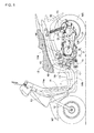
Fig. 2 is a sectional view taken along line 2-2 ofFig. 1 . -
Fig. 3 is an enlarged view of an area indicated by arrow 3 ofFig. 2 . -
Fig. 4 is a sectional view taken along line 4-4 ofFig. 2 . -
Fig. 5 is a sectional view taken along line 5-5 ofFig. 2 . -
Fig. 6 is a view of a state without a gasket shown inFig. 5 . -
Fig. 7 is a sectional view taken along line 7-7 ofFig. 4 . -
Fig. 8 is a sectional view taken along line 8-8 ofFig. 4 . -
Fig. 9 is a sectional view taken along line 9-9 ofFig. 6 . - Embodiments according to the present invention will be described with reference to
Fig. 1 to Fig. 9 . Incidentally, in the following description, each of the fore-and-aft, up-and-down and right-and-left directions shall refer to a direction when viewed from an occupant on the motorcycle. - Initially, in
Fig. 1 , the small vehicle is a scooter-type motorcycle having a low floor 11. A vehicle-body frame F of the motorcycle includes ahead pipe 13 supporting steerablyfront forks 12 journaling a front wheel WF, and a pair of right andleft side frames 14 joined at their front ends to thehead pipe 13. Theside frame 14 has, as an integrated piece, adown frame 14a which hangs downward from thehead pipe 13, alower frame 14b which is connected to the bottom end of thedown frame 14a and formed to extend rearward under the floor 11 and to have a rear half inclined upward and rearward, a risingframe 14c which is connected to a rear end of thelower frame 14b and rises upward at a more rearward position than the floor 11, and aseat rail 14d which extends rearward from the rear end of the risingframe 14c in order to support anoccupant seat 15. Theside frame 14 is shaped by bending a single pipe. -
Rear sub-frames 16 are provided between the rear portions of thelower frames 14b and the front portions of theseat rails 14d in theside frames 14 so as to be situated under theseat rails 14d and rearward of the risingframes 14c in theside frames 14.Pivot plates 17 are placed between both theside frames 14 and both therear sub-frames 16. - The
pivot plates 17 support vertically swingably a power unit P, which is made up of an engine E placed forward of a rear wheel WR which is the drive wheel and a power transmission M placed on the left side of the rear wheel WR, through alink mechanism 18 to allow it to swing in the up-and-down direction. The rear wheel WR is journaled to a rear portion of the power unit P. - In
Fig. 2 , anengine body 19 of the engine E which is a single-cylinder, 4-cycle water-cooled engine includes acrankcase 20 which is made up of two split right andleft crankcase halves cylinder block 21 which is coupled to thecrankcase 20, acylinder head 22 which is coupled to thecylinder block 21, and ahead cover 23 which is coupled to thecylinder head 22. A piston 25 is slidably fitted in acylinder bore 24 having a slightly forward and upward tilted cylinder axis and formed in thecylinder block 21. Thecrankcase 20 supports rotatably acrankshaft 26 extending in the width direction of the vehicle-body frame F, and the piston 25 is connected to thecrankshaft 26. - An
outer rotor 27 is fixed to a right end of thecrankshaft 26 extending rotatably through theright crankcase half 20R in thecrankcase 20. Aninner stator 28, which is enclosed with theouter rotor 27 in such manner as to, together with theouter rotor 27, form agenerator 29, is fixed to asupport plate 30 fastened to theright crankcase half 20R. - A
tubular generator cover 31 is coupled to theright crankcase half 20R and surrounds thegenerator 29. Aradiator 32 is arranged on the right side of thegenerator cover 31. Acooling fan 33 for flowing cooling air to theradiator 32 is secured to thecrankshaft 26 in a position between thegenerator 29 and theradiator 32. - Now, a
valve gear 36 is held between thecylinder head 22 and thehead cover 23 for operation of opening/closing an intake valve (not shown) for controlling the air intake into acombustion chamber 35 which is formed between thecylinder block 21 and thecylinder head 22 to be bordered by the top of the piston 25, and an exhaust valve (not shown) for controlling the exhaust from thecombustion chamber 35. Thevalve gear 36 includes acamshaft 37 which is movably supported in thecylinder head 22 to be able to rotate around the axis parallel to thecrankshaft 26. - A timing transmission 40 is installed between the
crankshaft 26 and thecamshaft 37 and includes acam chain 39 running in acam chain chamber 38 which is formed in an area from thecrankcase 20 to the cylinder head in theengine body 19. The timing transmission 40 transmits power from thecrankshaft 26 to thecamshaft 37 at a reduction ratio of one half. Apump shaft 42 of a cooling-water pump 41 mounted on the right side face of thecylinder head 22 is coupled coaxially to thecamshaft 37 while being prevented from rotating relative to it. The cooling-water pump 41 is connected to theradiator 32 through athermostat 43. - Referring to
Fig. 1 , anintake device 44 is connected to an upper side face of thecylinder head 22 in theengine body 19. Theintake device 44 includes an air cleaner 45, aninlet pipe 46 connected at the upstream end to the air cleaner 45, and athrottle body 47 provided between the downstream end of theinlet pipe 46 and thecylinder head 22. Afuel injection valve 48 for fuel injection into air measured by thethrottle body 47 is mounted to thecylinder head 22. Anexhaust device 49 connected to a lower side face of thecylinder head 22 includes anexhaust pipe 50 connected to a lower portion of thecylinder head 22 and extending from a right-side lower portion of theengine body 19 toward the right side of the rear wheel WR, and anexhaust muffler 51 connected to theexhaust pipe 50 and placed on the right side of the rear wheel WR. - The power transmission M includes a belt-type continuously
variable transmission 52 arranged contiguous to thecrankcase 20 and contained in the power-transmission case 54 extending toward the left side of the rear wheel WR, and agear mechanism 53 reducing the speed output from the continuouslyvariable transmission 52 for transmission of the output to theaxle 56 of the rear wheel WR. Thegear mechanism 53 is held within thegear case 55 attached to a rear portion of the power-transmission case 54. - The power-
transmission case 54 is made up of amain case 58 integrally adjoining theleft crankcase half 20L of thecrankcase 20 and extending rearward toward the left side of the rear wheel WR, and afirst cover 59 covering themain case 58 from without. The air cleaner 45 of theintake device 44 is supported by themain case 58 placed under the air cleaner 45. Thegear case 55 is made up of a rear portion of themain case 58 and asecond cover 60 joined to the rear portion of themain case 58 from within. Atransmission chamber 61 holding the belt-type continuouslyvariable transmission 52 is formed within the power-transmission case 54, while agear chamber 62 holding thegear mechanism 53 is formed within thegear case 55 so as to be located away from thecrank chamber 34 in thecrankcase 20. - The belt-type continuously
variable transmission 52 includes adrive pulley 63 mounted on thecrankshaft 26, a drivenpulley 64 mounted on a power-transmission shaft 66, and anendless V belt 65 looped around thedrive pulley 63 and the drivenpulley 64. Thedrive pulley 63 is provided at one end of thecrankshaft 26 extending from thecrankcase 20 into thetransmission chamber 61, while the drivenpulley 64 is provided on the power-transmission shaft 66 having the axis parallel to thecrankshaft 26 and supported rotatably by themain case 58, thefirst cover 59 and thesecond cover 60. - The
drive pulley 63 includes a fixed pulley half 67 fixed to thecrankshaft 26 and amovable pulley half 68 which is able to move toward/away from the fixed pulley half 67. Themovable pulley half 68 is driven in the axis direction by centrifugal force which acts on a weight roller 70 disposed between themovable pulley half 68 and aramp plate 69 secured to thecrankshaft 26. - The driven
pulley 64 includes a fixedpulley half 72 secured to a cylindricalinner tube 140 which coaxially surrounds the power-transmission shaft 66 while being relatively rotatably supported by the power-transmission shaft 66, and amovable pulley half 73 which is able to move relative to theinner tube 140 in the axis direction and rotate relative to theinner tube 140 and is allowed to move toward/away from the fixedpulley half 72 by being secured to anouter tube 141 coaxially surrounding theinner tube 140. TheV belt 65 is looped between the fixedpulley half 72 and themovable pulley half 73. In addition, atorque cam mechanism 74, which causes a component of force in the axis direction to act on between both the pulley halves 72, 73 in accordance with a relative-rotation phase difference between themovable pulley half 73 and the fixedpulley half 72, is provided between theinner tube 140 and theouter tube 141. Themovable pulley half 73 is elastically urged toward the fixedpulley half 72 by acoil spring 75, and a centrifugal clutch 76 is mounted between theinner tube 140 and the power-transmission shaft 66 and is switched to the power transmission state upon the engine speed exceeding a set engine speed. - Now, the fixed
pulley half 72 and themovable pulley half 73 are used by turning pulley halves of identical shape around 180 degrees. The inner peripheral portion of the fixedpulley half 72 is fixedly attached to one end portion of theinner tube 140 by ring mash welding. Also, the inner peripheral portion of themovable pulley half 73 is fixedly attached to one end portion of theouter tube 141 by the ring mash welding. In this manner, the pulley halves of identical shape are used to form the drivenpulley 64, thus achieving a reduction in the number of kinds of components. Ring mash welding is employed for fixed attachment, thus achieving an increase in productivity. - Then, a distance between the fixed
pulley half 72 and themovable pulley half 73 in the drivenpulley 64 in the axis direction is determined by a balance among an axial force generated by thetorque cam mechanism 74, an axial elastic force generated by thecoil spring 75 and a force from theV belt 65 acting in the direction of increasing the distance between the fixedpulley half 72 and themovable pulley half 73. By arranging themovable pulley half 68 closer to the fixed pulley half 67 in thedrive pulley 63, the loop radius of theV belt 65 over thedrive pulley 63 is increased, whereupon the loop radius of theV belt 65 over the drivenpulley 64 is decreased. - The
first cover 59 in the power-transmission case 54 supports rotatably akick shaft 77. Akick pedal 78 is provided at the outer end of thekick shaft 77. Akick starting device 79 is provided between thekick shaft 77 and thecrankshaft 26 on the inner surface of thefirst cover 59, and allows the rotating power of thekick shaft 77 in response to depression operation of thekick pedal 78 to be transmitted to thecrankshaft 26. A plurality offins 80 protrude from the outer surface of the fixed pulley half 67 in thedrive pulley 63 for causing the fixed pulley half 67 to serve a function as a cooling fan flowing cooling air into the power-transmission case 54. - One end of the
axle 56 of the rear wheel WR extends hermetically through thesecond cover 60 into thegear case 55, and is rotatably supported by themain case 58 and thesecond cover 60. Thegear mechanism 53 mounted between the power-transmission shaft 66 and theaxle 56 is held in thegear chamber 62. - A
swing arm 81 arranged contiguous to thecrankcase 20 of theengine body 19 is placed on the right side of the rear wheel WR. The other end of theaxle 56 is rotatably supported by a rear portion of theswing arm 81. In addition, as shown inFig. 1 , arear cushion unit 82 is provided between a rear portion of themain case 58 of the power-transmission case 54 and a rear portion of theleft seat rail 14d in the vehicle-body frame F. - In
Fig. 3 , thegear mechanism 53 has adrive gear 84 mounted integrally on the power-transmission shaft 66 to which the rotating power is transmitted from thecrankshaft 26, afinal gear 85 installed on theaxle 56 of the rear wheel WR and first and second counter gears 86, 87 arranged between thefinal gear 85 and thedrive gear 84, and is contained in thegear chamber 62. - Both the ends of the
counter shaft 88 are rotatably supported by themain case 58 and thesecond cover 60 which cooperate to form thegear case 55. Thefirst counter gear 86 of a larger diameter than that of thedrive gear 84 is fixed to thecounter shaft 88 in such a manner as to mesh with thedrive gear 84, while thesecond counter gear 87 of a smaller diameter than those of thefirst counter gear 86 and thefinal gear 85 is mounted integrally on thecounter shaft 88 in such a manner as to mesh with thefinal gear 85. - Additionally referring to
Fig. 4 , a first throughhole 89 is formed in themain case 58 to allow a middle portion of the power-transmission shaft 66 to extends rotatably through the first throughhole 89. A first supportingrecess 90 facing thegear chamber 62 is provided in themain case 58 such that one end of thecounter shaft 88 is inserted and disposed in the first supportingrecess 90, while a second supportingrecess 91 facing thegear chamber 62 is provided in themain case 58 such that one end of theaxle 56 is inserted and disposed in the second supportingrecess 91. - Referring to
Fig. 5 andFig. 6 together, a second throughhole 92 is formed in thesecond cover 60 to allow a middle portion of theaxle 56 to extends rotatably through the second throughhole 92. A third supportingrecess 93 facing thegear chamber 62 is provided in thesecond cover 60 such that the other end of the power-transmission shaft 66 is inserted and disposed in the third supportingrecess 93, while a fourth supportingrecess 94 facing thegear chamber 62 is provided in thesecond cover 60 such that the other end of thecounter shaft 88 is inserted and disposed in the fourth supportingrecess 94. - A ring-shaped sealing
member 95 and aball bearing 96 in order from thetransmission chamber 61 are interposed between the inner periphery of the first throughhole 89 and the outer periphery of the power-transmission shaft 66, while aball bearing 97 is interposed between the outer periphery of the other end of the power-transmission shaft 66 and the inner periphery of the third supportingrecess 93. Also, aball bearing 98 is interposed between the outer periphery of one end of thecounter shaft 88 and the inner periphery of the first supportingrecess 90, while aball bearing 99 is interposed between the outer periphery of the other end of thecounter shaft 88 and the inner periphery of the fourth supportingrecess 94. Then, aball bearing 100 is interposed between the outer periphery of one end of theaxle 56 of the rear wheel WR and the inner periphery of the second supportingrecess 91, while a ring-shapedsealing member 101 and aball bearing 102 in order from thegear chamber 62 are interposed between the outer periphery of the middle portion of theaxle 56 and the inner periphery of the second throughhole 92. - The power-
transmission shaft 66, thecounter shaft 88 and theaxle 56 are placed such that the power-transmission shaft 66, thecounter shaft 88 and theaxle 56 are arranged in this order from the front, and the rotation axis of theaxle 56, or equivalently, a rotation axis C1 of thefinal gear 85 is located on a higher level than the locations of the rotation axis of the power-transmission shaft 66, or equivalently, a rotation axis C2 of thedrive gear 84 and the rotation axis of thecounter shaft 88, or equivalently, a rotation axis C3 of the first and second counter gears 86, 87. - Oil used for lubrication is stored within the
gear chamber 62, in which a lower portion of thefinal gear 85 of the largest diameter of those of thegears 84 to 87 forming thegear mechanism 53 is immersed in the oil filling up to level L in a lower portion within thegear chamber 62. - Additionally referring to
Fig. 7 , an oilingrib 104 protrudes in thegear case 55. The oilingrib 104 is disposed above thefinal gear 85 and formed to extend toward thefinal gear 85 so that the oil delivered by the tooth tips of thefinal gear 85 returns toward thefinal gear 85 when thefinal gear 85 rotates in a rotation direction 103 (seeFig. 4 ) indicated by the arrow during the forward travel of the motorcycle. - The
gear case 55 is provided with anoil guide wall 105 which is formed in an arc shape along the tooth tips of thefinal gear 85 so as to guide the oil stored in the lower portion within thegear chamber 62 toward the oilingrib 104. In the embodiment, theoil guide wall 105 is provided flush with themain case 58 and thesecond cover 60 which cooperate to form thegear case 55. - Now, the
final gear 85 is mounted on theaxle 56 in a position closer to theball bearing 100 which is a bearing member interposed between one ends of themain case 58 of thegear case 55 and theaxle 56. The oilingrib 104 extending downward from the ceiling wall of thegear case 55 is formed on themain case 58 of thegear case 55 and the leading end of the oilingrib 104 is located near the tooth tips of thefinal gear 85. - Additionally referring to
Fig. 8 , themain case 58 of thegear case 55 is provided with a surroundingwall 106 extending toward thefinal gear 85 to surround theaxle 56 at least from below, andintroduction walls rib 104 so as to guide the oil toward the surroundingwall 106. - The surrounding
wall 106 protrudes from the opening edge of the second supportingrecess 91 provided in themain case 58 for supporting one end of theaxle 56, and, in the embodiment, is formed in an arc shape surrounding a lower half of theaxle 56 and a rear portion of theaxle 56. Also, theintroduction wall 107 integrally adjoins the rear end of the surroundingwall 106, and is formed to be inclined forward and downward while extending in the fore-and-aft direction. Theintroduction wall 108 is disposed above the surroundingwall 106 and directly below the oilingrib 104, and is formed to be inclined rearward and downward toward the rear end of the surroundingwall 106 while extending in the fore-and-aft direction. - Additionally referring to
Fig. 9 , thesecond cover 60 of thegear case 55 is provided integrally with an arc-shaped surroundingwall 109 extending toward thefirst counter gear 86 to surround thecounter shaft 88 from below such that the surroundingwall 109 protrudes from the opening edge of the fourth supportingrecess 94 formed in thesecond cover 60 for supporting the other end of thecounter shaft 88. - An
introduction wall 110 disposed diagonally upward and rearward of the fourth supportingrecess 94 protrudes from the inner surface of thesecond cover 60. Theintroduction wall 110 is formed to extend in the fore-and-aft direction while being inclined forward and downward such that the oil falling in drops from an upper portion within thegear case 55 is guided toward the surroundingwall 109. - In the
gear case 55 forward of thedrive gear 84, thefirst counter gear 86, thesecond counter gear 87 and thefinal gear 85, abreather chamber 111 is formed to extend in the up-and-down direction for emitting gas to the outside in the thermal expansion of gas with a rise in the oil temperature within thegear chamber 62. The oilingrib 104 is disposed between thebreather chamber 111 and theoil guide wall 105. - The
breather chamber 111 is formed between a portion of the outer peripheral walls of themain case 58 and thesecond cover 60, and rib-shapedsidewalls main case 58 and thesecond cover 60. First, third andsixth chambers breather chamber 111 is formed between thesecond cover 60 and agasket 115 sandwiched between themain case 58 and thesecond cover 60, while second, fourth andfifth chambers breather chamber 111 is formed between thegasket 115 and themain case 58. - A
recess 122 is provided in a lower end of thesidewall 113 in thesecond cover 60. The gas within thegear chamber 62 flows through between therecess 122 and thegasket 115 to be guided into thefirst chamber 116 of thebreather chamber 111. - The
main case 58 is provided with afirst partition wall 123 connecting thesidewall 113 and the outer peripheral wall of themain case 58 such that thefirst partition wall 123 abuts on thegasket 115 so as to isolate the second andfourth chambers second partition wall 124 interposed between thefourth chamber 119 and thefifth chamber 120 to connect thesidewall 113 and the outer peripheral wall of themain case 58. Thesecond partition wall 124 is formed such that a gap is formed to permit a flow of gas between thesecond partition wall 124 and thegasket 115 in order that the gas flows from thefourth chamber 119 to thefifth chamber 120. - The
second cover 60 is provided with athird partition wall 125 interposed between thefirst chamber 116 and the third chamber 118 to connect thesidewall 114 and the outer peripheral wall of thesecond cover 60. Thethird partition wall 125 is formed such that a gap is formed to permit a flow of gas between thethird partition wall 125 and thegasket 115 in order that the gas flows from thefirst chamber 116 to the third chamber 118. Also thesecond cover 60 is provided with afourth partition wall 126 to connect thesidewall 114 and the outer peripheral wall of thesecond cover 60 such that thefourth partition wall 126 abuts on thegasket 115 so as to isolate the third andsixth chambers - The
gasket 115 is provided with a first throughhole 127 for communication between lower portions of the first andsecond chambers hole 128 for communication between upper portions of the first andsecond chambers hole 129 for communication between lower portions of the third chamber 118 and thefourth chamber 119, a fourth throughhole 130 for communication between upper portions of the third chamber 118 and thefourth chamber 119, a fifth throughhole 131 for communication between lower portions of thefifth chamber 120 and thesixth chamber 121, and a sixth throughhole 132 for communication between upper portions of thefifth chamber 120 and thesixth chamber 121. The first, third and fifth throughholes holes - Thus, the gas flowing into the
first chamber 116 of thebreather chamber 111 flows between thefirst chamber 116 and thesecond chamber 117 via the first and second throughholes first chamber 116 to the third chamber 118 is guided to thefourth chamber 119 via the third and fourth throughholes fourth chamber 119 to thefifth chamber 120 is guided to thesixth chamber 121 via the fifth and sixth throughholes sixth chambers 116 to 121 communicate with each other in a labyrinth manner, so that the oil component entrained in the gas is separated from the gas within thebreather chamber 111. Also, the oil separated from the gas in the first tosixth chambers 116 to 121 flows sequentially into the chambers in order from higher to lower levels via the first, third and fifth throughholes recess 122 at the lower end of thesidewall 113 to thegear chamber 62. - The
second cover 60 is provided with a lead-outtube 133 having a leading end protruding into thesixth chamber 121 such that the lead-outtube 133 stands up from thesecond cover 60 in the upward direction. A breather tube, not shown, is connected to an outer end of the lead-outtube 133. - The
main case 58 of thegear case 55 is provided integrally with a rib-shapedcoupling wall 142 connecting the oilingrib 104 and thesidewall 113, and a rib-shapedcoupling wall 144 connecting thecoupling wall 142 and acylindrical bearing housing 143 formed integrally with themain case 58 in such a manner as to form the second supportingrecess 91. The oilingrib 104, thesidewall 113 and the bearinghousing 143 are coupled to each other through thecoupling walls rib 104, thesidewall 113 and the bearinghousing 143 can be reinforced and run performance in the process of casting themain case 58 can be increased. - A sensor, for example, a
wheel speed sensor 135 is attached to themain case 58 of thegear case 55 with abolt 136 such that the leading end of the sensor is placed near the tooth tips of thefinal gear 85. Thewheel speed sensor 135 is disposed between theoil guide wall 105 and the oilingrib 104 and downstream of theoil guide wall 105 in the flow direction of the oil flowing between theoil guide wall 105 and thefinal gear 85. - Next, operation of the embodiment will be described. The
gear chamber 62 formed within thegear case 55 contains thegear mechanism 53 which has thedrive gear 84 mounted integrally on the power-transmission shaft 66 to which rotation power is transmitted from thecrankshaft 26, thefinal gear 85 provided on theaxle 56 of the rear wheel WR, and the first and second counter gears 86, 87 arranged between thefinal gear 85 and thedrive gear 84. The rotation axis C1 of thefinal gear 85 with the lower portion being immersed into the oil stored in a lower portion within thegear chamber 62 is placed at a higher level than the rotation axis C2 of thedrive gear 84 and the rotation axis C3 of the first and second counter gears 86, 87. The oilingrib 104 disposed above thefinal gear 85 and extending toward thefinal gear 85 protrudes into thegear case 55. Theoil guide wall 105 formed in an arc shape along the tooth tips of thefinal gear 85 so as to guide the oil stored in the lower portion within thegear chamber 62 toward the oilingrib 104 is provided in thegear case 55. - Accordingly, rotational friction is reduced by decreasing the area of the
final gear 85 immersed into the oil and reducing the amount of oil delivered to thefinal gear 85. The splashed oil is guided toward thefinal gear 85 by using theoil guide wall 105 to guide the oil to the oilingrib 104 protruding into thegear case 55 so as to extend toward thefinal gear 85, thus ensuring the lubrication performance. - The
gear case 55 is fixed on the rear portion of the power-transmission case 54 provided contiguous to thecrankcase 20 of theengine body 19, extending toward the side of the rear wheel WR and containing the belt-type continuouslyvariable transmission 52 placed between thecrankshaft 26 and thedrive gear 84. Thebreather chamber 111 extending in the up-and-down direction is formed in thegear case 55 above thedrive gear 84 and the first and second counter gears 86, 87 and forward of thefinal gear 85. Because of these facts, by placing the rotation axis C1 of thefinal gear 85 at a higher level than the rotation axes C2, C31 of thedrive gear 84 and the counter gears 86, 87, this makes it possible to ensure space for thebreather chamber 111 extending in the up-and-down direction and configured to achieve sufficient gas-liquid separation capability, on front of thefinal gear 85 and above the drive gear and the counter gear while avoiding an increase in size of thegear case 55, resulting in an enhancement of gas-liquid separation capability. - The oiling
rib 104 placed between thebreather chamber 111 and theoil guide wall 105 is hung downward from the ceiling wall of thegear case 55 and has a leading end located near the tooth tips of thefinal gear 85. Because of this, while avoiding an increase in size of thegear case 55, the area of the oilingrib 104 facing theoil guide wall 105 can be ensured, so that a larger amount of oil can be collected and caught by use of the oilingrib 104 and then fall in drops toward thefinal gear 85, thus increasing the lubricating property. - The
gear case 55 is made up of themain case 58 forming part of the power-transmission case 54 and integrally adjoining thecrankcase 20, and thecover 60 coupled to the rear portion of themain case 58 so that thegear chamber 62 is formed between themain case 58 and thecover 60. One end of theaxle 56 of the rear wheel WR is rotatably supported through theball bearing 100 by themain case 58. Thefinal gear 85 is mounted on theaxle 56 in a position closer to theball bearing 100. Themain case 58 is provided with the surroundingwall 106 extending toward the final gear so as to surround theaxle 56 at least from below, and theintroduction walls rib 104 so as to guide the oil toward the surroundingwall 106. As a result, the oil falling in drops from the oilingrib 104 is guided from theintroduction walls wall 106, thus making it possible to effectively guide the oil into between themain case 58 and theaxle 56 to improve the lubrication performance. - Also, since the
introduction walls rib 104 toward the surroundingwall 106. - In addition, the oiling
rib 104 protrudes into themain case 58, and thewheel speed sensor 135, which is placed between theguide wall 105 and the oilingrib 104 on the downstream side of theoil guide wall 105 in a flow direction of the oil flowing between theoil guide wall 105 and thefinal gear 85, is installed on themain case 58 such that the leading end of thewheel speed sensor 135 is located near the tooth tips of thefinal gear 85. Because of this, the oil guided by theoil guide wall 105 collides with thewheel speed sensor 135, thereby producing the cleaning effect of oil on thewheel speed sensor 135. Also, the oil after colliding with thewheel speed sensor 135 and then dispersing sideways moves along the inner surface of themain case 58 toward the oilingrib 104, thus allowing a larger amount of oil to fall in drips from the oilingrib 104 so as to improve the lubricating property. - Up to this point an embodiment of the present invention has been described, but the present invention is not limited to the embodiment and various changes in design can be made without departing from the scope of the invention as defined by the appended claims.
- For example, the present invention can be applied to a power unit for three-wheeled vehicles as well as a motorcycle shown in the embodiment, and the present invention can be also applied to a power unit with a gear chamber separated from a crank chamber in a crankcase.
-
- 19 ... Engine body
- 20 ... Crankcase
- 26 ... Crankshaft
- 34 ... Crank chamber
- 52 ... Belt-type continuous variable transmission
- 53 ... Gear mechanism
- 54 ... Power-transmission case
- 55 ... Gear case
- 56 ... Axle
- 58 ... Main case
- 60 ... Second cover which is cover
- 62 ... Gear chamber
- 84 ... Drive gear
- 85 ... Final gear
- 86, 87 ... Counter gear
- 100 ... Ball bearing which is bearing member
- 104 ... Oiling rib
- 105 ... Oil guide wall
- 106 ... Surrounding wall
- 107, 108 ... Introduction wall
- 111 ... Breather chamber
- 135 ... Wheel speed sensor which is sensor
- C1 ... Rotation axis of final gear
- C2 ... Rotation axis of drive gear
- C3 ... Rotation axis of counter gear
- P ... Power unit
- WR ... Rear wheel which is drive wheel
Claims (6)
- Lubrication structure of a gear chamber in a power unit for a small vehicle comprising:a gear chamber (62) that is formed within a gear case (55) attached to an engine body (19) including a crankcase (20) with a crank chamber (34) formed therein and is isolated from the crank chamber (34); anda gear mechanism (53) that has a drive gear (84) to which power is transmitted from a crankshaft (26) rotatably supported in the crankcase (20), a final gear (85) mounted on an axle (56) of a drive wheel (WR), and counter gears (86, 87) arranged between the final gear (85) and the drive gear (84) and is contained within the gear chamber (62),wherein: a rotation axis (C1) of the final gear (85) having a lower portion immersed in oil stored in a lower portion within the gear chamber (62) is placed at a higher level than rotation axes (C2, C3) of the drive gear (84) and the counter gears (86, 87);an oiling rib (104) placed above the final gear (85) and extending toward the final gear (85) protrudes into the gear case (55); andthe gear case (55) is provided with an oil guide wall (105) formed in an arc shape along tooth tips of the final gear (85) to guide oil stored in the lower portion within the gear chamber (62) to the oiling rib (104).
- The lubricating structure of a gear chamber in a power unit for a small vehicle according to claim 1, wherein the gear case (55) is attached to a rear portion of a power-transmission case (54) adjoining the crankcase (20), extending toward a side of the drive wheel (WR) and containing a belt-type continuously variable transmission (52) placed between the crankshaft (26) and the drive gear (84), and a breather chamber (111) extending in an up-and-down direction is formed above the drive gear (84) and the counter gears (86, 87) and in front of the final gear (85) in the gear case (55).
- The lubricating structure of a gear chamber in a power unit for a small vehicle according to claim 2, wherein the oiling rib (104) placed between the breather chamber (111) and the oil guide wall (105) is hung down from a ceiling wall of the gear case (55) and has a leading end placed near the tooth tips of the final gear (85).
- The lubricating structure of a gear chamber in a power unit for a small vehicle according to claim 3, wherein the gear case (55) includes a main case (58) forming a part of the power-transmission case (54) and integrally adjoining the crankcase (20), and a cover (60) coupled to a rear portion of the main case (58) and causing the gear chamber (62) to be formed between the main case (58) and the cover (60), one end of the axle (56) is rotatably supported through a bearing member (100) by the main case (58), the final gear (85) is mounted on the axle (56) in a position closer to the bearing member (100), and the main case (58) is provided with a surrounding wall (106) extending toward the final gear (85) and surrounding the axle (56) at least from below, and introduction walls (107, 108) placed below the oiling rib (104) to guide oil toward the surrounding wall (106).
- The lubricating structure of a gear chamber in a power unit for a small vehicle according to claim 4, wherein the introduction walls (107, 108) are formed to extend in a fore-and-aft direction.
- The lubricating structure of a gear chamber in a power unit for a small vehicle according to claim 2, wherein the oiling rib (104) protrudes into the main case (58), and a sensor (135) placed between the guide wall (105) and the oiling rib (104) on a downstream side of the oil guide wall (105) in a flow direction of oil flowing between the oil guide wall (105) and the final gear (85) is mounted to the main case (58) and has a leading end placed near tooth tips of the final gear (85).
Applications Claiming Priority (1)
| Application Number | Priority Date | Filing Date | Title |
|---|---|---|---|
| JP2011154464A JP5687148B2 (en) | 2011-07-13 | 2011-07-13 | Lubrication structure of gear chamber in power unit for small vehicle |
Publications (3)
| Publication Number | Publication Date |
|---|---|
| EP2546551A2 true EP2546551A2 (en) | 2013-01-16 |
| EP2546551A3 EP2546551A3 (en) | 2016-01-27 |
| EP2546551B1 EP2546551B1 (en) | 2017-08-16 |
Family
ID=46507908
Family Applications (1)
| Application Number | Title | Priority Date | Filing Date |
|---|---|---|---|
| EP12175540.9A Active EP2546551B1 (en) | 2011-07-13 | 2012-07-09 | Power unit for a small vehicle |
Country Status (3)
| Country | Link |
|---|---|
| EP (1) | EP2546551B1 (en) |
| JP (1) | JP5687148B2 (en) |
| ES (1) | ES2647868T3 (en) |
Cited By (5)
| Publication number | Priority date | Publication date | Assignee | Title |
|---|---|---|---|---|
| EP2551551A3 (en) * | 2011-07-23 | 2013-09-11 | Honda Motor Co., Ltd. | Power unit for small vehicle |
| GB2535816A (en) * | 2015-06-19 | 2016-08-31 | Daimler Ag | Housing element for a differential gear of a vehicle |
| EP3534040A1 (en) * | 2018-03-01 | 2019-09-04 | Yamaha Hatsudoki Kabushiki Kaisha | Straddled vehicle |
| CN111828598A (en) * | 2019-04-19 | 2020-10-27 | 丰田自动车株式会社 | Lubricating mechanism for power transmission device for vehicle |
| CN113738858A (en) * | 2021-08-13 | 2021-12-03 | 麦格纳动力总成(江西)有限公司 | Wet-type double-clutch transmission and automobile |
Families Citing this family (1)
| Publication number | Priority date | Publication date | Assignee | Title |
|---|---|---|---|---|
| JP6600189B2 (en) * | 2015-07-28 | 2019-10-30 | 日野自動車株式会社 | Oil supply structure to bearing |
Family Cites Families (5)
| Publication number | Priority date | Publication date | Assignee | Title |
|---|---|---|---|---|
| JPS582852B2 (en) * | 1978-04-15 | 1983-01-19 | 本田技研工業株式会社 | Lubricating device for differential gear equipment |
| JPS6131576Y2 (en) * | 1980-07-25 | 1986-09-13 | ||
| JPS61186714U (en) * | 1985-05-14 | 1986-11-21 | ||
| JP2696329B2 (en) * | 1988-01-30 | 1998-01-14 | ヤマハ発動機株式会社 | Gear shaft lubrication device |
| JPH11108163A (en) * | 1997-10-08 | 1999-04-20 | Toyota Motor Corp | Lubricating device |
-
2011
- 2011-07-13 JP JP2011154464A patent/JP5687148B2/en not_active Expired - Fee Related
-
2012
- 2012-07-09 ES ES12175540.9T patent/ES2647868T3/en active Active
- 2012-07-09 EP EP12175540.9A patent/EP2546551B1/en active Active
Non-Patent Citations (1)
| Title |
|---|
| None |
Cited By (6)
| Publication number | Priority date | Publication date | Assignee | Title |
|---|---|---|---|---|
| EP2551551A3 (en) * | 2011-07-23 | 2013-09-11 | Honda Motor Co., Ltd. | Power unit for small vehicle |
| GB2535816A (en) * | 2015-06-19 | 2016-08-31 | Daimler Ag | Housing element for a differential gear of a vehicle |
| EP3534040A1 (en) * | 2018-03-01 | 2019-09-04 | Yamaha Hatsudoki Kabushiki Kaisha | Straddled vehicle |
| CN111828598A (en) * | 2019-04-19 | 2020-10-27 | 丰田自动车株式会社 | Lubricating mechanism for power transmission device for vehicle |
| CN111828598B (en) * | 2019-04-19 | 2023-11-03 | 丰田自动车株式会社 | Lubrication mechanism for power transmission device for vehicle |
| CN113738858A (en) * | 2021-08-13 | 2021-12-03 | 麦格纳动力总成(江西)有限公司 | Wet-type double-clutch transmission and automobile |
Also Published As
| Publication number | Publication date |
|---|---|
| JP5687148B2 (en) | 2015-03-18 |
| EP2546551B1 (en) | 2017-08-16 |
| EP2546551A3 (en) | 2016-01-27 |
| JP2013019500A (en) | 2013-01-31 |
| ES2647868T3 (en) | 2017-12-27 |
Similar Documents
| Publication | Publication Date | Title |
|---|---|---|
| EP2546551B1 (en) | Power unit for a small vehicle | |
| US7610987B2 (en) | Power unit and saddle-ride type vehicle provided with the power unit | |
| EP2543834B1 (en) | Breather structure of motorcycle engine | |
| CN101960175A (en) | Power unit for vehicle | |
| JP2008223880A (en) | Internal combustion engine and vehicle equipped with the same | |
| JP5486872B2 (en) | Power unit cooling system | |
| CN101713313B (en) | Configuration structure for oil level gage of engine | |
| JP5227922B2 (en) | Torque damper device for saddle-ride type vehicles | |
| JP4728310B2 (en) | Exhaust pipe device for motorcycle | |
| CN101713332B (en) | An internal combustion engine | |
| TWI235192B (en) | Oil return construction of 4-cycle engine | |
| JP4556611B2 (en) | Motorcycle power unit | |
| JP7380924B2 (en) | internal combustion engine | |
| JP5353538B2 (en) | Cam chain lubrication structure for motorcycle engines | |
| KR20100109377A (en) | Internal combustion engine with kick-type starter | |
| JP5138528B2 (en) | Engine cooling structure | |
| JP2011047366A (en) | Lubricating device of motorcycle engine | |
| JPH0949433A (en) | Cam chain tensioner device for four-cycle horizontal engine | |
| JP2005351115A (en) | Oil pump installing structure of internal combustion engine | |
| JP5323883B2 (en) | Motorcycle internal combustion engine | |
| JP2011163191A (en) | Wire routing structure of engine | |
| JP2010196899A (en) | Motorcycle | |
| CN101960176A (en) | Power unit for vehicle | |
| JP2005291052A (en) | Lubrication structure for internal combustion engine | |
| JP2004218488A (en) | Engine unit for vehicle |
Legal Events
| Date | Code | Title | Description |
|---|---|---|---|
| PUAI | Public reference made under article 153(3) epc to a published international application that has entered the european phase |
Free format text: ORIGINAL CODE: 0009012 |
|
| 17P | Request for examination filed |
Effective date: 20120709 |
|
| AK | Designated contracting states |
Kind code of ref document: A2 Designated state(s): AL AT BE BG CH CY CZ DE DK EE ES FI FR GB GR HR HU IE IS IT LI LT LU LV MC MK MT NL NO PL PT RO RS SE SI SK SM TR |
|
| AX | Request for extension of the european patent |
Extension state: BA ME |
|
| PUAL | Search report despatched |
Free format text: ORIGINAL CODE: 0009013 |
|
| AK | Designated contracting states |
Kind code of ref document: A3 Designated state(s): AL AT BE BG CH CY CZ DE DK EE ES FI FR GB GR HR HU IE IS IT LI LT LU LV MC MK MT NL NO PL PT RO RS SE SI SK SM TR |
|
| AX | Request for extension of the european patent |
Extension state: BA ME |
|
| RIC1 | Information provided on ipc code assigned before grant |
Ipc: F16H 59/38 20060101ALN20151218BHEP Ipc: F16H 57/027 20120101ALI20151218BHEP Ipc: F16H 57/02 20120101ALN20151218BHEP Ipc: F16H 57/04 20060101AFI20151218BHEP Ipc: F16H 57/035 20120101ALN20151218BHEP |
|
| RBV | Designated contracting states (corrected) |
Designated state(s): AL AT BE BG CH CY CZ DE DK EE ES FI FR GB GR HR HU IE IS IT LI LT LU LV MC MK MT NL NO PL PT RO RS SE SI SK SM TR |
|
| 17Q | First examination report despatched |
Effective date: 20160810 |
|
| STAA | Information on the status of an ep patent application or granted ep patent |
Free format text: STATUS: EXAMINATION IS IN PROGRESS |
|
| GRAP | Despatch of communication of intention to grant a patent |
Free format text: ORIGINAL CODE: EPIDOSNIGR1 |
|
| STAA | Information on the status of an ep patent application or granted ep patent |
Free format text: STATUS: GRANT OF PATENT IS INTENDED |
|
| RIC1 | Information provided on ipc code assigned before grant |
Ipc: F16H 57/02 20120101ALN20170324BHEP Ipc: F16H 57/04 20100101AFI20170324BHEP Ipc: F16H 59/38 20060101ALN20170324BHEP Ipc: F16H 57/035 20120101ALN20170324BHEP Ipc: F16H 57/027 20120101ALI20170324BHEP |
|
| INTG | Intention to grant announced |
Effective date: 20170502 |
|
| GRAS | Grant fee paid |
Free format text: ORIGINAL CODE: EPIDOSNIGR3 |
|
| GRAA | (expected) grant |
Free format text: ORIGINAL CODE: 0009210 |
|
| STAA | Information on the status of an ep patent application or granted ep patent |
Free format text: STATUS: THE PATENT HAS BEEN GRANTED |
|
| AK | Designated contracting states |
Kind code of ref document: B1 Designated state(s): AL AT BE BG CH CY CZ DE DK EE ES FI FR GB GR HR HU IE IS IT LI LT LU LV MC MK MT NL NO PL PT RO RS SE SI SK SM TR |
|
| REG | Reference to a national code |
Ref country code: GB Ref legal event code: FG4D |
|
| REG | Reference to a national code |
Ref country code: CH Ref legal event code: EP |
|
| REG | Reference to a national code |
Ref country code: IE Ref legal event code: FG4D |
|
| REG | Reference to a national code |
Ref country code: AT Ref legal event code: REF Ref document number: 919377 Country of ref document: AT Kind code of ref document: T Effective date: 20170915 |
|
| REG | Reference to a national code |
Ref country code: DE Ref legal event code: R096 Ref document number: 602012035907 Country of ref document: DE |
|
| REG | Reference to a national code |
Ref country code: NL Ref legal event code: MP Effective date: 20170816 |
|
| REG | Reference to a national code |
Ref country code: ES Ref legal event code: FG2A Ref document number: 2647868 Country of ref document: ES Kind code of ref document: T3 Effective date: 20171227 |
|
| REG | Reference to a national code |
Ref country code: LT Ref legal event code: MG4D |
|
| REG | Reference to a national code |
Ref country code: AT Ref legal event code: MK05 Ref document number: 919377 Country of ref document: AT Kind code of ref document: T Effective date: 20170816 |
|
| PG25 | Lapsed in a contracting state [announced via postgrant information from national office to epo] |
Ref country code: SE Free format text: LAPSE BECAUSE OF FAILURE TO SUBMIT A TRANSLATION OF THE DESCRIPTION OR TO PAY THE FEE WITHIN THE PRESCRIBED TIME-LIMIT Effective date: 20170816 Ref country code: NL Free format text: LAPSE BECAUSE OF FAILURE TO SUBMIT A TRANSLATION OF THE DESCRIPTION OR TO PAY THE FEE WITHIN THE PRESCRIBED TIME-LIMIT Effective date: 20170816 Ref country code: FI Free format text: LAPSE BECAUSE OF FAILURE TO SUBMIT A TRANSLATION OF THE DESCRIPTION OR TO PAY THE FEE WITHIN THE PRESCRIBED TIME-LIMIT Effective date: 20170816 Ref country code: AT Free format text: LAPSE BECAUSE OF FAILURE TO SUBMIT A TRANSLATION OF THE DESCRIPTION OR TO PAY THE FEE WITHIN THE PRESCRIBED TIME-LIMIT Effective date: 20170816 Ref country code: NO Free format text: LAPSE BECAUSE OF FAILURE TO SUBMIT A TRANSLATION OF THE DESCRIPTION OR TO PAY THE FEE WITHIN THE PRESCRIBED TIME-LIMIT Effective date: 20171116 Ref country code: LT Free format text: LAPSE BECAUSE OF FAILURE TO SUBMIT A TRANSLATION OF THE DESCRIPTION OR TO PAY THE FEE WITHIN THE PRESCRIBED TIME-LIMIT Effective date: 20170816 |
|
| PG25 | Lapsed in a contracting state [announced via postgrant information from national office to epo] |
Ref country code: RS Free format text: LAPSE BECAUSE OF FAILURE TO SUBMIT A TRANSLATION OF THE DESCRIPTION OR TO PAY THE FEE WITHIN THE PRESCRIBED TIME-LIMIT Effective date: 20170816 Ref country code: PL Free format text: LAPSE BECAUSE OF FAILURE TO SUBMIT A TRANSLATION OF THE DESCRIPTION OR TO PAY THE FEE WITHIN THE PRESCRIBED TIME-LIMIT Effective date: 20170816 Ref country code: LV Free format text: LAPSE BECAUSE OF FAILURE TO SUBMIT A TRANSLATION OF THE DESCRIPTION OR TO PAY THE FEE WITHIN THE PRESCRIBED TIME-LIMIT Effective date: 20170816 Ref country code: GR Free format text: LAPSE BECAUSE OF FAILURE TO SUBMIT A TRANSLATION OF THE DESCRIPTION OR TO PAY THE FEE WITHIN THE PRESCRIBED TIME-LIMIT Effective date: 20171117 Ref country code: IS Free format text: LAPSE BECAUSE OF FAILURE TO SUBMIT A TRANSLATION OF THE DESCRIPTION OR TO PAY THE FEE WITHIN THE PRESCRIBED TIME-LIMIT Effective date: 20171216 Ref country code: BG Free format text: LAPSE BECAUSE OF FAILURE TO SUBMIT A TRANSLATION OF THE DESCRIPTION OR TO PAY THE FEE WITHIN THE PRESCRIBED TIME-LIMIT Effective date: 20171116 |
|
| PG25 | Lapsed in a contracting state [announced via postgrant information from national office to epo] |
Ref country code: DK Free format text: LAPSE BECAUSE OF FAILURE TO SUBMIT A TRANSLATION OF THE DESCRIPTION OR TO PAY THE FEE WITHIN THE PRESCRIBED TIME-LIMIT Effective date: 20170816 Ref country code: CZ Free format text: LAPSE BECAUSE OF FAILURE TO SUBMIT A TRANSLATION OF THE DESCRIPTION OR TO PAY THE FEE WITHIN THE PRESCRIBED TIME-LIMIT Effective date: 20170816 Ref country code: RO Free format text: LAPSE BECAUSE OF FAILURE TO SUBMIT A TRANSLATION OF THE DESCRIPTION OR TO PAY THE FEE WITHIN THE PRESCRIBED TIME-LIMIT Effective date: 20170816 |
|
| REG | Reference to a national code |
Ref country code: DE Ref legal event code: R097 Ref document number: 602012035907 Country of ref document: DE |
|
| PG25 | Lapsed in a contracting state [announced via postgrant information from national office to epo] |
Ref country code: EE Free format text: LAPSE BECAUSE OF FAILURE TO SUBMIT A TRANSLATION OF THE DESCRIPTION OR TO PAY THE FEE WITHIN THE PRESCRIBED TIME-LIMIT Effective date: 20170816 Ref country code: SK Free format text: LAPSE BECAUSE OF FAILURE TO SUBMIT A TRANSLATION OF THE DESCRIPTION OR TO PAY THE FEE WITHIN THE PRESCRIBED TIME-LIMIT Effective date: 20170816 Ref country code: SM Free format text: LAPSE BECAUSE OF FAILURE TO SUBMIT A TRANSLATION OF THE DESCRIPTION OR TO PAY THE FEE WITHIN THE PRESCRIBED TIME-LIMIT Effective date: 20170816 |
|
| REG | Reference to a national code |
Ref country code: FR Ref legal event code: PLFP Year of fee payment: 7 |
|
| PLBE | No opposition filed within time limit |
Free format text: ORIGINAL CODE: 0009261 |
|
| STAA | Information on the status of an ep patent application or granted ep patent |
Free format text: STATUS: NO OPPOSITION FILED WITHIN TIME LIMIT |
|
| 26N | No opposition filed |
Effective date: 20180517 |
|
| PG25 | Lapsed in a contracting state [announced via postgrant information from national office to epo] |
Ref country code: SI Free format text: LAPSE BECAUSE OF FAILURE TO SUBMIT A TRANSLATION OF THE DESCRIPTION OR TO PAY THE FEE WITHIN THE PRESCRIBED TIME-LIMIT Effective date: 20170816 |
|
| REG | Reference to a national code |
Ref country code: DE Ref legal event code: R119 Ref document number: 602012035907 Country of ref document: DE |
|
| REG | Reference to a national code |
Ref country code: CH Ref legal event code: PL |
|
| GBPC | Gb: european patent ceased through non-payment of renewal fee |
Effective date: 20180709 |
|
| PG25 | Lapsed in a contracting state [announced via postgrant information from national office to epo] |
Ref country code: LU Free format text: LAPSE BECAUSE OF NON-PAYMENT OF DUE FEES Effective date: 20180709 Ref country code: MC Free format text: LAPSE BECAUSE OF FAILURE TO SUBMIT A TRANSLATION OF THE DESCRIPTION OR TO PAY THE FEE WITHIN THE PRESCRIBED TIME-LIMIT Effective date: 20170816 |
|
| REG | Reference to a national code |
Ref country code: BE Ref legal event code: MM Effective date: 20180731 |
|
| REG | Reference to a national code |
Ref country code: IE Ref legal event code: MM4A |
|
| PG25 | Lapsed in a contracting state [announced via postgrant information from national office to epo] |
Ref country code: DE Free format text: LAPSE BECAUSE OF NON-PAYMENT OF DUE FEES Effective date: 20190201 Ref country code: CH Free format text: LAPSE BECAUSE OF NON-PAYMENT OF DUE FEES Effective date: 20180731 Ref country code: LI Free format text: LAPSE BECAUSE OF NON-PAYMENT OF DUE FEES Effective date: 20180731 Ref country code: IE Free format text: LAPSE BECAUSE OF NON-PAYMENT OF DUE FEES Effective date: 20180709 Ref country code: GB Free format text: LAPSE BECAUSE OF NON-PAYMENT OF DUE FEES Effective date: 20180709 |
|
| PG25 | Lapsed in a contracting state [announced via postgrant information from national office to epo] |
Ref country code: BE Free format text: LAPSE BECAUSE OF NON-PAYMENT OF DUE FEES Effective date: 20180731 |
|
| PGFP | Annual fee paid to national office [announced via postgrant information from national office to epo] |
Ref country code: FR Payment date: 20190619 Year of fee payment: 8 |
|
| PGFP | Annual fee paid to national office [announced via postgrant information from national office to epo] |
Ref country code: ES Payment date: 20190801 Year of fee payment: 8 |
|
| PG25 | Lapsed in a contracting state [announced via postgrant information from national office to epo] |
Ref country code: MT Free format text: LAPSE BECAUSE OF NON-PAYMENT OF DUE FEES Effective date: 20180709 |
|
| PG25 | Lapsed in a contracting state [announced via postgrant information from national office to epo] |
Ref country code: TR Free format text: LAPSE BECAUSE OF FAILURE TO SUBMIT A TRANSLATION OF THE DESCRIPTION OR TO PAY THE FEE WITHIN THE PRESCRIBED TIME-LIMIT Effective date: 20170816 |
|
| PG25 | Lapsed in a contracting state [announced via postgrant information from national office to epo] |
Ref country code: PT Free format text: LAPSE BECAUSE OF FAILURE TO SUBMIT A TRANSLATION OF THE DESCRIPTION OR TO PAY THE FEE WITHIN THE PRESCRIBED TIME-LIMIT Effective date: 20170816 Ref country code: HU Free format text: LAPSE BECAUSE OF FAILURE TO SUBMIT A TRANSLATION OF THE DESCRIPTION OR TO PAY THE FEE WITHIN THE PRESCRIBED TIME-LIMIT; INVALID AB INITIO Effective date: 20120709 |
|
| PG25 | Lapsed in a contracting state [announced via postgrant information from national office to epo] |
Ref country code: MK Free format text: LAPSE BECAUSE OF NON-PAYMENT OF DUE FEES Effective date: 20170816 Ref country code: HR Free format text: LAPSE BECAUSE OF FAILURE TO SUBMIT A TRANSLATION OF THE DESCRIPTION OR TO PAY THE FEE WITHIN THE PRESCRIBED TIME-LIMIT Effective date: 20170816 Ref country code: CY Free format text: LAPSE BECAUSE OF FAILURE TO SUBMIT A TRANSLATION OF THE DESCRIPTION OR TO PAY THE FEE WITHIN THE PRESCRIBED TIME-LIMIT Effective date: 20170816 |
|
| PG25 | Lapsed in a contracting state [announced via postgrant information from national office to epo] |
Ref country code: AL Free format text: LAPSE BECAUSE OF FAILURE TO SUBMIT A TRANSLATION OF THE DESCRIPTION OR TO PAY THE FEE WITHIN THE PRESCRIBED TIME-LIMIT Effective date: 20170816 |
|
| PG25 | Lapsed in a contracting state [announced via postgrant information from national office to epo] |
Ref country code: FR Free format text: LAPSE BECAUSE OF NON-PAYMENT OF DUE FEES Effective date: 20200731 |
|
| REG | Reference to a national code |
Ref country code: ES Ref legal event code: FD2A Effective date: 20211228 |
|
| PG25 | Lapsed in a contracting state [announced via postgrant information from national office to epo] |
Ref country code: ES Free format text: LAPSE BECAUSE OF NON-PAYMENT OF DUE FEES Effective date: 20200710 |
|
| PGFP | Annual fee paid to national office [announced via postgrant information from national office to epo] |
Ref country code: IT Payment date: 20230612 Year of fee payment: 12 |