EP2474368A1 - Edge guide of curtain coater - Google Patents
Edge guide of curtain coater Download PDFInfo
- Publication number
- EP2474368A1 EP2474368A1 EP10811686A EP10811686A EP2474368A1 EP 2474368 A1 EP2474368 A1 EP 2474368A1 EP 10811686 A EP10811686 A EP 10811686A EP 10811686 A EP10811686 A EP 10811686A EP 2474368 A1 EP2474368 A1 EP 2474368A1
- Authority
- EP
- European Patent Office
- Prior art keywords
- edge guide
- coating material
- groove
- web
- lubricating liquid
- Prior art date
- Legal status (The legal status is an assumption and is not a legal conclusion. Google has not performed a legal analysis and makes no representation as to the accuracy of the status listed.)
- Withdrawn
Links
- 238000000576 coating method Methods 0.000 claims description 113
- 239000011248 coating agent Substances 0.000 claims description 112
- 239000000463 material Substances 0.000 claims description 83
- 239000007788 liquid Substances 0.000 claims description 53
- 230000001050 lubricating effect Effects 0.000 claims description 49
- 239000000203 mixture Substances 0.000 claims description 4
- 230000000630 rising effect Effects 0.000 claims description 4
- 239000010687 lubricating oil Substances 0.000 abstract 5
- 239000010410 layer Substances 0.000 description 15
- 239000002184 metal Substances 0.000 description 14
- 241001122767 Theaceae Species 0.000 description 11
- 230000000694 effects Effects 0.000 description 5
- 238000000926 separation method Methods 0.000 description 5
- 238000012423 maintenance Methods 0.000 description 4
- 238000000034 method Methods 0.000 description 4
- 238000011144 upstream manufacturing Methods 0.000 description 4
- 230000000903 blocking effect Effects 0.000 description 3
- 238000007766 curtain coating Methods 0.000 description 3
- 238000007639 printing Methods 0.000 description 3
- XLYOFNOQVPJJNP-UHFFFAOYSA-N water Substances O XLYOFNOQVPJJNP-UHFFFAOYSA-N 0.000 description 3
- 230000002950 deficient Effects 0.000 description 2
- 238000010586 diagram Methods 0.000 description 2
- 238000007599 discharging Methods 0.000 description 2
- 238000005516 engineering process Methods 0.000 description 2
- 239000002356 single layer Substances 0.000 description 2
- 238000013519 translation Methods 0.000 description 2
- 241000270295 Serpentes Species 0.000 description 1
- 238000005299 abrasion Methods 0.000 description 1
- 238000004891 communication Methods 0.000 description 1
- 238000010276 construction Methods 0.000 description 1
- 238000011109 contamination Methods 0.000 description 1
- 125000004122 cyclic group Chemical group 0.000 description 1
- 230000003247 decreasing effect Effects 0.000 description 1
- 238000001035 drying Methods 0.000 description 1
- 238000004519 manufacturing process Methods 0.000 description 1
- 238000012986 modification Methods 0.000 description 1
- 230000004048 modification Effects 0.000 description 1
- 229910001220 stainless steel Inorganic materials 0.000 description 1
- 239000010935 stainless steel Substances 0.000 description 1
- 230000003068 static effect Effects 0.000 description 1
Images



Classifications
-
- B—PERFORMING OPERATIONS; TRANSPORTING
- B05—SPRAYING OR ATOMISING IN GENERAL; APPLYING FLUENT MATERIALS TO SURFACES, IN GENERAL
- B05C—APPARATUS FOR APPLYING FLUENT MATERIALS TO SURFACES, IN GENERAL
- B05C5/00—Apparatus in which liquid or other fluent material is projected, poured or allowed to flow on to the surface of the work
- B05C5/007—Slide-hopper coaters, i.e. apparatus in which the liquid or other fluent material flows freely on an inclined surface before contacting the work
- B05C5/008—Slide-hopper curtain coaters
-
- D—TEXTILES; PAPER
- D21—PAPER-MAKING; PRODUCTION OF CELLULOSE
- D21H—PULP COMPOSITIONS; PREPARATION THEREOF NOT COVERED BY SUBCLASSES D21C OR D21D; IMPREGNATING OR COATING OF PAPER; TREATMENT OF FINISHED PAPER NOT COVERED BY CLASS B31 OR SUBCLASS D21G; PAPER NOT OTHERWISE PROVIDED FOR
- D21H23/00—Processes or apparatus for adding material to the pulp or to the paper
- D21H23/02—Processes or apparatus for adding material to the pulp or to the paper characterised by the manner in which substances are added
- D21H23/22—Addition to the formed paper
- D21H23/46—Pouring or allowing the fluid to flow in a continuous stream on to the surface, the entire stream being carried away by the paper
- D21H23/48—Curtain coaters
-
- B—PERFORMING OPERATIONS; TRANSPORTING
- B05—SPRAYING OR ATOMISING IN GENERAL; APPLYING FLUENT MATERIALS TO SURFACES, IN GENERAL
- B05D—PROCESSES FOR APPLYING FLUENT MATERIALS TO SURFACES, IN GENERAL
- B05D1/00—Processes for applying liquids or other fluent materials
- B05D1/26—Processes for applying liquids or other fluent materials performed by applying the liquid or other fluent material from an outlet device in contact with, or almost in contact with, the surface
-
- B—PERFORMING OPERATIONS; TRANSPORTING
- B05—SPRAYING OR ATOMISING IN GENERAL; APPLYING FLUENT MATERIALS TO SURFACES, IN GENERAL
- B05D—PROCESSES FOR APPLYING FLUENT MATERIALS TO SURFACES, IN GENERAL
- B05D1/00—Processes for applying liquids or other fluent materials
- B05D1/30—Processes for applying liquids or other fluent materials performed by gravity only, i.e. flow coating
- B05D1/305—Curtain coating
-
- B—PERFORMING OPERATIONS; TRANSPORTING
- B05—SPRAYING OR ATOMISING IN GENERAL; APPLYING FLUENT MATERIALS TO SURFACES, IN GENERAL
- B05D—PROCESSES FOR APPLYING FLUENT MATERIALS TO SURFACES, IN GENERAL
- B05D1/00—Processes for applying liquids or other fluent materials
- B05D1/34—Applying different liquids or other fluent materials simultaneously
-
- B—PERFORMING OPERATIONS; TRANSPORTING
- B05—SPRAYING OR ATOMISING IN GENERAL; APPLYING FLUENT MATERIALS TO SURFACES, IN GENERAL
- B05D—PROCESSES FOR APPLYING FLUENT MATERIALS TO SURFACES, IN GENERAL
- B05D2252/00—Sheets
- B05D2252/02—Sheets of indefinite length
Definitions
- the present invention relates to a curtain coater, and more particularly, to an edge guide for a curtain coater.
- Coated paper such as printing paper used for printing brochure or catalog, carbonless duplicating paper and thermal recording paper is manufactured by coating a coating material on a web (base material), that is, base paper, by a coater, and then by drying the coated web.
- the machine for coating a coating material is called a coater.
- coaters such as a blade coater, a rod coater and an air knife coater that adopt the post-metering method predominated as mainstream of coaters.
- an excessive amount of coating material is firstly coated on a web, then an excessively coated coating material is scratched off by a blade or a rod of small diameter, or is blown off by an air knife, and metering is performed.
- curtain coaters in which a curtain film of a coating material is spouted onto a running web from a die (a chamber with nozzle that forms a curtain film of coating material) to coat the web with the coating material, have been widely used.
- curtain coaters have long been used in the field of photographic printing paper or the like, they were not used in the paper manufacturing industry. This is because coating by using the curtain coaters was not stable due to engulfing of air at a high speed of 1000m/min or greater, bubbles got mixed into coating material, unstableness of the curtain film caused by an insufficient mechanical accuracy, etc.
- the curtain coating machine is advantageous in that it is easy in maintenance because it does not have consumable components such as blades and rods, it can adjust the amount of coating easily with a high accuracy, it is user friendly with good operability, it is highly effective in improving surface properties because it employs contour coating, and so on.
- a curtain film of coating material falls by its own weight when it is separated from a die. At that moment, edges are pulled inward by a surface tension of the coating material, resulting in neck-in in which width of the curtain film becomes narrower. When the neck-in occurs, the both end portions of the curtain film becomes thicker. If the curtain film with the end portions thereof being thickened is coated on a web as it is, corresponding web portions will be thickly coated, resulting in insufficient desiccation for that portions, which will cause a so-called blocking phenomenon in which paper sticks to each other when it is rolled up.
- the width of a curtain film is made greater than that of a web, and portions of the curtain film that protrude beyond the web are received by edge pans provided below the web so that the coating material is reused as a cyclic usage.
- coating materials are likely to be mixed with each other. Therefore, such a conventional coating method cannot be employed. Instead, coated-up coating must be performed in which, the width of a curtain film being made smaller than that of a web, all of the coating material of the curtain film is coated on the web, and non-coated portions (dry edges) are left to be present in both end portions of the web. Therefore, in order to prevent such a neck-in, an edge guide is provided.
- FIG 8 is a conceptual diagram of such an edge guide.
- A represents a die
- B represents an edge guide
- c represents a curtain film of coating material
- w represents a web.
- the edge guide B is made of metal such as stainless steel to prevent the neck-in.
- flow speed v of the curtain film c of the coating material is slow in the neighborhood of the edge guide 2 as shown in Figure 8 , and is uniform in areas other than in the neighborhood of the edge guide B. If the flow rate of the curtain film c of the coating material is small in the above situation, the curtain film c flows away from the edge guide B, resulting in the occurrence of the neck-in.
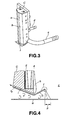
- FIGS 3 and 4 are a perspective view and a partial cross sectional view of an edge guide disclosed in patent document 1, respectively.
- C represents a main body of the edge guide
- a represents a guide surface
- b represents inclined planes provided at both sides of the guide surface a
- d represents a lubricating liquid supplying tube
- e represents a lubricating liquid discharging tube
- f represents a metal separation sheet.
- the guide surface a is an arc-shaped surface of a porous pipe through which a lubricating liquid weeps. An entirety of the porous pipe is embedded in a groove formed in the edge guide main body C, with the arc-shaped guide surface a of the porous pipe being exposed from the groove.
- the edge guide main body C when shown in a plane cross-sectional view, is shaped as a mountain with the guide surface a being a peak thereof.
- a bottom face of the edge guide main body A is an inclined face, a front end thereof (inner side in a web width direction) being positioned in the lowest and getting higher toward an rear end thereof (outer side in the web width direction).
- the metal separation sheet f is attached to the bottom face.
- the metal separation sheet f is bent in the neighborhood of the front end of the edge guide main body C with the bent portion being positioned the lowest, and has an inclined surface f1 that becomes higher toward the forward direction (inner side in a web width direction) and an inclined surfaced that becomes higher toward the backward direction (outer side in the web width direction).
- Figure 4 is a cross-sectional view of a lower end portion of the edge guide, which is cut away by a vertical face that is perpendicular to the moving direction of the web w.
- g represents the porous pipe, a part of which is formed to be the arc-shaped guide surface a that is exposed from the groove of the edge guide main body C
- h represents a lubricating liquid
- i represents a groove formed in the bottom face of the edge guide main body C.
- the groove i is covered with the metal separation sheet f to form a channel for a mixed liquid of the lubricating liquid h and a coating material. This channel is communicated with the lubricating liquid discharging tube e, which is sucked up by a suction pump not shown in the drawings.
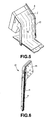
- Figures 5 and 6 illustrate another example of the edge guide disclosed in patent document 2, in which Figure 5 is an overall perspective view including an edge guide, and Figure 6 is a perspective view of the edge guide.
- D represents the edge guide
- j represents a guide plate
- k represents a slide edge guide.
- a coating material which is discharged upward from a die, flows on the guide plate j, free-falls from a downward-facing lower end portion of the guide plate j in the form of a curtain film c, and collides with the web w to be coated on the web w.
- To both sides of the guide plate j are attached the respective slide edge guides k to define both ends of the flow of the coating material on the guide plate j.
- an edge guide main body o having a groove portion n through which a lubricating liquid flows extends downward from the upper end portion m.
- Figure 7 is an enlarged horizontal sectional view of the groove portion n.
- the groove portion n is configured such as to sandwich the curtain film c from the both sides thereof, and is provided with a number of grooves and peaks that are arranged consecutively in a zigzag manner.
- the width of the groove (or peak) is 0.5mm and the angle between two intersecting bottoms of the groove is 90 degree, and therefore, the depth of the groove portion n is 0.25mm.
- the width of the whole of the groove portion n is 10-12mm.
- a suction port through which a mixed liquid of a lubricating liquid and a coating material is sucked.
- Height of the aperture of the suction port is 0.1-1mm.
- the lower end of the edge guide main body o is touched softly with the web w, and is formed to be an inclined surface that rises toward the outer side in the web width direction from the touching point.
- the present invention has been made in view of the aforementioned problems in the related art, and an object of the present invention is to provide an edge guide for a curtain coater capable of holding the edges of a curtain film stably along the groove of the edge guide, saving a maintenance labor, suppressing the fluttering of both end portions of a web w when the web w runs at a high speed, and dealing with the tea pot phenomenon.
- an edge guide for a curtain coater including a guide plate that comprises an inclined portion having an upper surface along which a coating material spouting out from one, or two or more, dies flows, and a guide portion extending from a lower end of the inclined portion toward a downward direction, wherein the edge guide is arranged as a pair in such a manner as to sandwich both end portions of a curtain film of a coating material flowing downward from the guide plate to coat the coating material on an upper surface of a web running at a high speed, and a lubricating liquid flows on an inner surface of the edge guide to lessen a hindrance against a flow of the curtain film of the coating material due to viscosity between the curtain film and the inner surface of the edge guide thereby to prevent a neck-in, wherein the edge guide comprises a supply port disposed in a neighborhood of an upper end of the inner surface thereof, through which the lubricating liquid is supplied, a suction port disposed in
- the invention recited in claim 2 provides an edge guide for a curtain coater, wherein the edge guide is arranged as a pair in such a manner as to sandwich both end portions of a curtain film of a coating material that spouts out from a die and flows downward to coat a coating material on an upper surface of a web running at a high speed, and a lubricating liquid flows on an inner surface of the edge guide to lessen a hindrance against a flow of the curtain film of the coating material due to viscosity between the curtain film and the inner surface of the edge guide thereby to prevent a neck-in, wherein the edge guide comprises a supply port disposed in a neighborhood of an upper end of the inner surface thereof, through which the lubricating liquid is supplied, a suction port disposed in a neighborhood of a lower end of the inner surface thereof, through which a mixture of the lubricating liquid and a coating material is sucked, a groove disposed in a belt-shaped region between the supply port of the lubric
- the width of the groove is preferably from 2mm to 4mm.
- the lower surface of the edge guides is in parallel with a surface of paper, and the height thereof is adjustable either to be slightly higher, the same, or slightly lower compared with the height of the running web.
- Figure 1 illustrates an edge guide for a curtain coater according to an exemplary embodiment of the present invention, in which Figure 1A is a front view viewed from inside, and Figure 1B is a side view.
- Figure 2A is a cross-sectional view taken along lines A-A and Figure 2B is a plan view of the edge guide for a curtain coater.
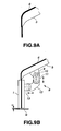
- Figure 9 illustrates the guide plate to which the edge guide is attached, in which Figure 9A illustrates a guide plate being cut off at an inner side of an edge guide attaching portion to explain the tea pot phenomenon, and Figure 9B is a side view illustrating the edge guide which is attached to the guide plate.
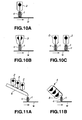
- Figures 10A through 10C illustrate the edge guide being attached to a die, in which Figure 10A illustrates a single-layer coating, Figure 10B illustrates a two-layer coating with a single die, and Figure 10C illustrates a two-layer coating with two dies.
- Figure 11 illustrates a multilayer coating with a use of a guide plate, in which Figure 11A illustrates coating on a web in which three dies are juxtaposed with each other on the guide plate to form a flow of three-layer coating materials, which in turn is coated on a web as a curtain film of the coating materials and Figure 11B illustrates coating on a web in which three dies that spout out a coating material upward are combined with each other to form a flow of three-layer coating materials on the guide plate, which in turn is coated on a web as a curtain film of the coating materials.
- Figure 12 is a horizontal cross-sectional view of the edge guide illustrating the relationship between the curtain film and the edge guide.
- 2 represents a die
- w represents a web
- c represents a curtain film, wherein the web w runs in an arrow direction.
- the edge guide 1 is arranged to sandwich the curtain film c at both end thereof
- 3 is a die.
- the die 3 is configured with two dies being combined into a single body
- the curtain film c is a two-layer coating material film. Components other than the die are the same as in Figure 10A , and description thereof is omitted.
- two-layer coating is realized with use of two dies.
- the guide plate 5 represents a guide plate.
- the guide plate 5 includes an inclined face and a curtain guide portion provided in a downward direction at a lower end of the inclined face.
- the guide plate 5 allows coating materials spouted out one after another from these three dies toward the inclined face to move along the inclined face to laminate the coating materials in order, thereby to form a three-layer of coating materials, which is then transferred from the curtain guide portion provided in a downward direction at the lower end of the inclined face onto a surface of the web w as a three-layer curtain film c.
- Components other than the foregoing is the same as in Figure 10A , and therefore description thereof is omitted.
- 4 represents a die that is configured with three dies that spout out a coating material obliquely upward being combined into a single body. Coating materials spouted out one after another from the three dies toward the inclined face of the guide plate 5 are allowed to move along the inclined face to laminate the coating materials in order, thereby to form a three-layer of coating materials, which is then transferred from the curtain guide portion provided in a downward direction at the lower end of the inclined face onto a surface of the web w as a three-layer curtain film c.
- 1 represents an edge guide.
- the edge guide 1 is in a rectangular shape in a front view, and an inner surface 19 thereof is provided with a vertically extending protrusion 20 with a groove 21 being a center thereof
- an upper surface 1a of the edge guide 1 forms an inclined surface, and a lower surface 1b is in parallel with a face of paper.
- the protrusion 20 is provided with the vertically extending groove 21 at the center thereof, and inclined surfaces 22 are formed at both sides of the groove 21, thereby to be shaped as a mountain with the groove 21 being a peak thereof.
- the inner surface 21 of the edge guide 1 is not limited to be shaped as such a protrusion, but an entirety of the inner surface 2 may be shaped as a mountain with the groove 21 being a peak thereof
- t represents a coating material coated on the web w.
- the groove 21 has a width of 2 - 4mm.
- Figure 2A shows that the groove 21 is in a circular arc shape, the groove 21 may be in a triangular shape with a vertex thereof being at the center of the groove.
- the angle ⁇ of the inclined surface 22 is preferably 15 - 90 degrees.
- h represents a lubricating liquid such as water
- 24 represents a connection port of the lubricating liquid h, the connection port being connected to a lubricating liquid supply tube which is not shown in the figures.
- 24a represents a lubricating liquid channel communicated with the lubricating liquid connection port 24.
- the lubricating liquid channel 24a curves in a U-shape at an upper portion thereof which is connected to an upper end of the groove 21 to form a lubricating liquid supply port 25, through which the lubricating liquid h flows into the groove 21.
- flow rate of the lubricating liquid such as water is about 10 - 100cc/min for each edge guide, and viscosity of the coating material is 100 - 2000mPa-s (Brookfield viscosity).
- the lower end of the groove 21 is connected to a suction port 26 through which a mixed liquid of the lubricating liquid h and the coating material is sucked.
- the suction port 26 has a height of 0.5 - 1.5 mm and a width of 3 - 5mm.
- a suction room 26a inside the suction port is formed a suction room 26a.
- a bottom board 1b of the suction chamber 26a extends forward.
- a lower face of the bottom board 1b is in parallel with the face of paper.
- Reference numeral 27 represents a suction connecting port connected to a vacuum suction pump not shown in the drawings via a communication pipe not shown in the drawings.
- Degree of vacuum inside the suction chamber 26a is about - 90 through - 98kPa.
- Reference symbol q represents an exhaust gas.
- FIG. 9B 8 represents an edge guide mounting device
- 9 represents a bracket attached to a rear face of the guide plate 5
- 10 represents a bolt formed with an external thread and a key groove at a base end portion thereof
- the base end portion of the bolt 10 is slidably inserted into a round hole provided at a lower portion of the bracket 9.
- a key is attached fixedly to the round hole such that the key is slidable in the key groove of the bolt 10, whereby the bolt 10 can slide in the round hole of the bracket 9 without being rotated.
- the position of the bolt 10 can be fixed by tightening up two nuts, not shown in the figure, screw threaded at the base end portion of the bolt 10 such as to pinch the lower end of the bracket 9. By loosening the two nuts screw threaded at the base end portion of the bolt 10, the position of the bolt 10 becomes adjustable in the web width direction so that the position of the edge guide 1 becomes adjustable in the web width direction.
- An attachment metal 11 is fixed to an fore end of the bolt 10.
- the attachment metal 11 is formed with two vertically-elongated oval holes at a lower portion thereof
- Reference numeral 12 represents an L-shaped metal fitting, one end face thereof being a horizontal plane and the other end face being a vertical plane, both end portions being formed with respective two threaded holes, on which bolts are screw threaded.
- Reference numeral 13 represents a bracket mounted horizontally on the edge guide 1.
- the bracket 13 is formed with two horizontally-elongated oval holes at a fore end portion thereof.
- the four bolts screw threaded at the L-shaped metal fitting 12 pass through the aforementioned vertically or horizontally elongated oval holes.
- the attachment metal 11 and the L-shaped metal fitting 12, or the L-shaped metal fitting 12 and the bracket 13 are fixed to each other.
- the position of the edge guide 1 becomes adjustable in the web running direction and in the up and down direction with respect to the lower end of the guide portion of the guide plate 5.
- the edge guide 1 is directly attached to the die 2 or die 3 as shown in Figure 10 . Since the tea pot phenomenon will never occur in the curtain film c spouted out from the die 2 or die 3, it is not necessary for the position of the edge guide 1 to be adjusted in the web running direction. This will be explained in reference to Figure 9 .
- the invention recited in claim 2 differs from the construction illustrated in Figure 9B in that a. the bracket 9 is attached not to the guide plate 5, but to the die 2 or die 3, and b.
- the position of the upper end of the edge guide 1 is only be adjustable with respect to the coating material spouting port of the die 2 in the web with direction and the up and down direction, but is not adjustable in the web running direction.
- the position of an upper end of the edge guide 1 is finely adjustable relative to the lower end of the guide portion of the guide plate 5 in the up and down direction, which enables to prevent the both end portions of a web w from flapping if the lower surface 1b of the edge guides 1 is made in parallel with a surface of paper.
- a gap u between the lower surface of the edge guide 1 and the upper surface of the web w is adjustable within a range between -1mm and +2mm.
- "-1mm" represents a state in which the both end portions of the web w is pushed downward by 1 mm.
- Both ends 21 a of the both sides of the groove 21 rises to form sharp edges and the inclined surfaces are formed outside the groove 21, which prevents the edges of a curtain film of coating material from being departed from the groove even if the curtain film c of the coating material swings, or the curtain film c is deviated in the web running direction by the tea pot phenomenon.
- This is explained in reference to Figure 12 .
- the lubricating liquid h flows in the groove 21 of the edge guide 1
- the lubricating liquid h flows in a state in which the lubricating liquid h rises toward left and right due to the both side ends 21a of the groove 21 that rise to form sharp edges and due to the action of surface tension.
Landscapes
- Coating Apparatus (AREA)
Abstract
Provided is an edge guide (1) which is improved in retainability and stability. The edge guides are provided in a pair to prevent neck-in. The edge guide (1) has a supply opening (25) for supplying a liquid lubricant (h) near the upper end of the inside face (19), and an intake opening (26) for taking in the liquid lubricant near the lower end of the inside face (19). In the belt-like zone between the liquid lubricant supplying opening (25) and the liquid lubricant intake opening (26) on the inside face (19), a groove (21) is provided for flow of the liquid lubricant. The outer sides of the groove (21) have respectively an inclined face (22), and the both sides of the groove rise to form sharp edges. The position of the upper end of the edge guide (1) is adjustable in the web progress direction, the web breadth directions, and vertical up- and-down directions relative to the lower end of the guide plate (5).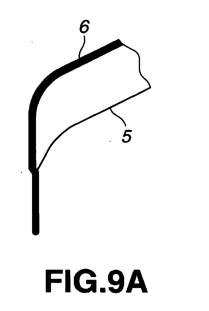
Description
- The present invention relates to a curtain coater, and more particularly, to an edge guide for a curtain coater.
- Coated paper such as printing paper used for printing brochure or catalog, carbonless duplicating paper and thermal recording paper is manufactured by coating a coating material on a web (base material), that is, base paper, by a coater, and then by drying the coated web. The machine for coating a coating material is called a coater. Conventionally, coaters such as a blade coater, a rod coater and an air knife coater that adopt the post-metering method predominated as mainstream of coaters. In the post-metering method, an excessive amount of coating material is firstly coated on a web, then an excessively coated coating material is scratched off by a blade or a rod of small diameter, or is blown off by an air knife, and metering is performed. However, there have been problems in the coating by the post-metering method that a large amount of the coating material is infiltrated inside a web due to a liquid pressure or compressing force by a blade when the coating material is coated on a web, and a maintenance cost is high due to an abrasion of blades, rods, etc.
- Recently, curtain coaters in which a curtain film of a coating material is spouted onto a running web from a die (a chamber with nozzle that forms a curtain film of coating material) to coat the web with the coating material, have been widely used. Although curtain coaters have long been used in the field of photographic printing paper or the like, they were not used in the paper manufacturing industry. This is because coating by using the curtain coaters was not stable due to engulfing of air at a high speed of 1000m/min or greater, bubbles got mixed into coating material, unstableness of the curtain film caused by an insufficient mechanical accuracy, etc.
- The applicant of this application has solved these problems and developed the curtain coating technology into a stable technology, and has been supplying a large number of curtain coating machines throughout the world. Unlike coating machines of conventional post-metering method, the curtain coating machine is advantageous in that it is easy in maintenance because it does not have consumable components such as blades and rods, it can adjust the amount of coating easily with a high accuracy, it is user friendly with good operability, it is highly effective in improving surface properties because it employs contour coating, and so on.
- Meanwhile, a curtain film of coating material falls by its own weight when it is separated from a die. At that moment, edges are pulled inward by a surface tension of the coating material, resulting in neck-in in which width of the curtain film becomes narrower. When the neck-in occurs, the both end portions of the curtain film becomes thicker. If the curtain film with the end portions thereof being thickened is coated on a web as it is, corresponding web portions will be thickly coated, resulting in insufficient desiccation for that portions, which will cause a so-called blocking phenomenon in which paper sticks to each other when it is rolled up. Conventionally, the width of a curtain film is made greater than that of a web, and portions of the curtain film that protrude beyond the web are received by edge pans provided below the web so that the coating material is reused as a cyclic usage. However, in a multi-layer curtain coater where two or more dies are used, coating materials are likely to be mixed with each other. Therefore, such a conventional coating method cannot be employed. Instead, coated-up coating must be performed in which, the width of a curtain film being made smaller than that of a web, all of the coating material of the curtain film is coated on the web, and non-coated portions (dry edges) are left to be present in both end portions of the web. Therefore, in order to prevent such a neck-in, an edge guide is provided.
-
Figure 8 is a conceptual diagram of such an edge guide. InFigure 8 , A represents a die, B represents an edge guide, c represents a curtain film of coating material and w represents a web. The edge guide B is made of metal such as stainless steel to prevent the neck-in. However, since a coating material has viscosity which hinders the flow of the coating material, flow speed v of the curtain film c of the coating material is slow in the neighborhood of theedge guide 2 as shown inFigure 8 , and is uniform in areas other than in the neighborhood of the edge guide B. If the flow rate of the curtain film c of the coating material is small in the above situation, the curtain film c flows away from the edge guide B, resulting in the occurrence of the neck-in. - To lessen such a phenomenon, it has been conducted to flow a lubricating liquid such as water over the surface of the
edge guide 2.Figures 3 and 4 are a perspective view and a partial cross sectional view of an edge guide disclosed inpatent document 1, respectively. - Referring to
Figure 3 , C represents a main body of the edge guide, a represents a guide surface, b represents inclined planes provided at both sides of the guide surface a, d represents a lubricating liquid supplying tube, e represents a lubricating liquid discharging tube, and f represents a metal separation sheet. The guide surface a is an arc-shaped surface of a porous pipe through which a lubricating liquid weeps. An entirety of the porous pipe is embedded in a groove formed in the edge guide main body C, with the arc-shaped guide surface a of the porous pipe being exposed from the groove. The edge guide main body C, when shown in a plane cross-sectional view, is shaped as a mountain with the guide surface a being a peak thereof. - A bottom face of the edge guide main body A is an inclined face, a front end thereof (inner side in a web width direction) being positioned in the lowest and getting higher toward an rear end thereof (outer side in the web width direction). The metal separation sheet f is attached to the bottom face. The metal separation sheet f is bent in the neighborhood of the front end of the edge guide main body C with the bent portion being positioned the lowest, and has an inclined surface f1 that becomes higher toward the forward direction (inner side in a web width direction) and an inclined surfaced that becomes higher toward the backward direction (outer side in the web width direction).
-
Figure 4 is a cross-sectional view of a lower end portion of the edge guide, which is cut away by a vertical face that is perpendicular to the moving direction of the web w. Referring toFigure 4 , g represents the porous pipe, a part of which is formed to be the arc-shaped guide surface a that is exposed from the groove of the edge guide main body C, h represents a lubricating liquid, and i represents a groove formed in the bottom face of the edge guide main body C. The groove i is covered with the metal separation sheet f to form a channel for a mixed liquid of the lubricating liquid h and a coating material. This channel is communicated with the lubricating liquid discharging tube e, which is sucked up by a suction pump not shown in the drawings. -
Figures 5 and 6 illustrate another example of the edge guide disclosed inpatent document 2, in whichFigure 5 is an overall perspective view including an edge guide, andFigure 6 is a perspective view of the edge guide. Referring toFigure 5 , D represents the edge guide, j represents a guide plate, and k represents a slide edge guide. A coating material, which is discharged upward from a die, flows on the guide plate j, free-falls from a downward-facing lower end portion of the guide plate j in the form of a curtain film c, and collides with the web w to be coated on the web w. To both sides of the guide plate j are attached the respective slide edge guides k to define both ends of the flow of the coating material on the guide plate j. - To the lower end of the slide edge guide k is attached an upper end portion m of the edge guide D. As shown in
Figure 6 , an edge guide main body o having a groove portion n through which a lubricating liquid flows extends downward from the upper end portion m.Figure 7 is an enlarged horizontal sectional view of the groove portion n. As shown inFigure 7 , the groove portion n is configured such as to sandwich the curtain film c from the both sides thereof, and is provided with a number of grooves and peaks that are arranged consecutively in a zigzag manner. The width of the groove (or peak) is 0.5mm and the angle between two intersecting bottoms of the groove is 90 degree, and therefore, the depth of the groove portion n is 0.25mm. The width of the whole of the groove portion n is 10-12mm. - At the lower end of the groove portion n of the edge guide main body o is provided a suction port through which a mixed liquid of a lubricating liquid and a coating material is sucked. Height of the aperture of the suction port is 0.1-1mm. The lower end of the edge guide main body o is touched softly with the web w, and is formed to be an inclined surface that rises toward the outer side in the web width direction from the touching point.
-
- [Patent document 1] Published Japanese Translation No.
2008-529753 - [Patent document 2] Published Japanese Translation No.
2005-512767 - The invention disclosed in the
patent document 1 described with reference toFigures 3 and 4 contains the problems as follows. - a. A lubricating liquid supplied inside the porous pipe g eventually weeps out through the porous body and flows downward. Since the porous body is easily blocked up with a passage of time due to a large flow volume of the lubricating liquid, the lubricating liquid will not be able to weep out. Thus, it is necessary to replace the porous pipe with a new one frequently, which results in troublesome task and high cost in maintenance.
- b. As shown in
Figure 4 , the metal separation sheet f attached to the bottom face of the edge guide main body C has an inclined surface f1 that becomes higher toward a forward direction (inner side in a web width direction), which causes the curtain film c to be in a neck-in p during a period when the curtain film c drops from the upper end of the inclined surface f1 onto the web w. As a result, portions of the web w corresponding to the both end portions of the coating will be coated too thickly, resulting in insufficient desiccation in that portions. - c. At the upper end of the inclined surface f1, a part of the coating material in the curtain film c moves around to the rear of the inclined surface f1, which flies apart as a splash, causing contamination of a dry edge on the web w.
- d. High speed running of the web w generates a disturbed flow of air as shown in
Figure 4 , which makes a portion where the disturbed flow of air occurs an unstable air pressure region. As a result, the both end portions of the web w will flap, and the end portions of the coating material coated on the web w will wind like a snake. - The invention disclosed in the
patent document 2 described with reference toFigures 5 through 7 contains the problems as follows. - A. The edge guide D is fixed to the slide edge guide k, which causes the following problems.
- a. Position of the edge guide main body o cannot be finely adjusted in a running direction of the web w, which makes it unable to cope with the tea pot phenomenon described later with reference to drawing. The tea pot phenomenon is a phenomenon in which the curtain film c is slightly moves around toward the upstream side when the flow of the coating material departs from the guide plate j and falls downward as the curtain film c.
- b. Position of the edge guide main body o cannot be finely adjusted in the up and down direction, which makes it unable to finely adjust the relative position between the lower end of the edge guide main body o and a path line of the web w. Thus, the fluttering of the both end portions of the web w cannot be suppressed.
- c. Position of the edge guide main body o cannot be adjusted in the width direction, which makes it unable to adjust the width of coating.
- B. The lower end of the edge guide main body o is formed as an inclined surface that rises from the inner side toward the outer side in the web width direction. As a result, as described with reference to
Figure 4 , a disturbed flow of air is generated in a region defined between the bottom face of the edge guide main body o and the upper face of the web w, which causes the web w to flap. - C. The width of the whole of the groove portion n is wide, i.e., as wide as 10-12mm. As a result, when the position of the curtain film c swings in the running direction of the web w under the influence of the tea pot phenomenon, wind, etc., the both end portions of the curtain film c is easy to move within the width of the whole of the groove portion n. As a result, a trace of the original flow has been dried, and attached to the top portion of the peaks shown in
Figure 7 , which results in a cause of disturbance of edges of the curtain film c. - The present invention has been made in view of the aforementioned problems in the related art, and an object of the present invention is to provide an edge guide for a curtain coater capable of holding the edges of a curtain film stably along the groove of the edge guide, saving a maintenance labor, suppressing the fluttering of both end portions of a web w when the web w runs at a high speed, and dealing with the tea pot phenomenon.
- To achieve the aforementioned object, the invention recited in claim 1 provides an edge guide for a curtain coater including a guide plate that comprises an inclined portion having an upper surface along which a coating material spouting out from one, or two or more, dies flows, and a guide portion extending from a lower end of the inclined portion toward a downward direction, wherein the edge guide is arranged as a pair in such a manner as to sandwich both end portions of a curtain film of a coating material flowing downward from the guide plate to coat the coating material on an upper surface of a web running at a high speed, and a lubricating liquid flows on an inner surface of the edge guide to lessen a hindrance against a flow of the curtain film of the coating material due to viscosity between the curtain film and the inner surface of the edge guide thereby to prevent a neck-in, wherein the edge guide comprises a supply port disposed in a neighborhood of an upper end of the inner surface thereof, through which the lubricating liquid is supplied, a suction port disposed in a neighborhood of a lower end of the inner surface thereof, through which a mixture of the lubricating liquid and a coating material is sucked, a groove disposed in a belt-shaped region between the supply port of the lubricating liquid and the suction port, through which the lubricating liquid flows, outside of the groove are formed inclined surfaces such as to be shaped as a mountain with the groove being a peak thereof in a plane cross-sectional view, both side ends of the groove rising to form sharp edges, wherein position of an upper end of the edge guide is adjustable relative to a lower end of the guide portion of the guide plate in a web running direction, in a web width direction and in up and down directions.
- The invention recited in claim 2 provides an edge guide for a curtain coater, wherein the edge guide is arranged as a pair in such a manner as to sandwich both end portions of a curtain film of a coating material that spouts out from a die and flows downward to coat a coating material on an upper surface of a web running at a high speed, and a lubricating liquid flows on an inner surface of the edge guide to lessen a hindrance against a flow of the curtain film of the coating material due to viscosity between the curtain film and the inner surface of the edge guide thereby to prevent a neck-in, wherein the edge guide comprises a supply port disposed in a neighborhood of an upper end of the inner surface thereof, through which the lubricating liquid is supplied, a suction port disposed in a neighborhood of a lower end of the inner surface thereof, through which a mixture of the lubricating liquid and a coating material is sucked, a groove disposed in a belt-shaped region between the supply port of the lubricating liquid and the suction port, through which the lubricating liquid flows, outside of the groove are formed inclined surfaces such as to be shaped as a mountain with the groove being a peak thereof in a plane cross-sectional view, both side ends of the groove rising to form sharp edges, wherein position of an upper end of the edge guide is adjustable relative to a coating material spouting port of the die in a web width direction and in up and down directions.
- The width of the groove is preferably from 2mm to 4mm.
- It is preferable that the lower surface of the edge guides is in parallel with a surface of paper, and the height thereof is adjustable either to be slightly higher, the same, or slightly lower compared with the height of the running web.
- Function and advantageous effect of the invention recited in
claim 1 are as follows. - a. The position of an upper end of the edge guide is finely adjustable relative to the lower end of the guide portion of the guide plate in the web running direction, which enables to cope with the tea pot phenomenon.
- b. The position of an upper end of the edge guide is fmely adjustable relative to the lower end of the guide portion of the guide plate in the up and down direction, which enables to prevent the both end portions of a web from flapping if the lower surface of the edge guides is made in parallel with a surface of paper.
- c. Both ends of the both sides of the groove rises to form sharp edges and the inclined surfaces are formed outside the groove, which prevents the edges of a curtain film of coating material from being departed from the groove even if the curtain film of coating material swings.
- d. As a result, stable coating as well as coating at a higher speed become possible, and there are produced no defective products due to blocking by insufficient desiccation caused by thick coating in the both end portions of the coating, and therefore coated paper is improved in quality.
- Function and advantageous effect of the invention recited in
claim 2 are the same as the function and advantageous effect of the invention recited inclaim 1 except for the item a., and therefore description is omitted. -
-
Figure 1 illustrates an edge guide for a curtain coater according to an example of the present invention, in whichFigure 1A is a front view viewed from inside, andFigure 1B is a side view; -
Figure 2A is a cross-sectional view taken along lines A-A; -
Figure 2B is a plan view of the edge guide for a curtain coater; -
Figure 3 is a perspective view of an edge guide disclosed in thepatent document 1; -
Figure 4 is a partial cross-sectional view of the edge guide disclosed in thepatent document 1; -
Figure 5 is an overall perspective view including an edge guide disclosed in thepatent document 2; -
Figure 6 is a perspective view of the edge guide disclosed in thepatent document 2; -
Figure 7 is an enlarged horizontal sectional view of a groove portion disclosed in thepatent document 2; -
Figure 8 is a conceptual diagram of a conventional edge guide; -
Figure 9A illustrates a guide plate being cut off at an inner side of an edge guide attaching portion; -
Figure 9B is a side view illustrating the edge guide being attached to the guide plate; -
Figure 10 illustrates the edge guide being attached to a die, in whichFigure 10A illustrates a single-layer coating,Figure 10B illustrates a two-layer coating with a single die, andFigure 10C illustrates a two-layer coating with two dies; -
Figure 11A illustrates coating on a web in which three dies are juxtaposed with each other on the guide plate to form a flow of three-layer coating materials, which in turn is coated on a web as a curtain film of the coating materials, and -
Figure 11B illustrates coating on a web in which three dies that spout out a coating material upward are combined with each other to form a flow of three-layer coating materials on the guide plate, which in turn is coated on a web as a curtain film of the coating materials; and -
Figure 12 is a horizontal cross-sectional view of the edge guide illustrating the relationship between the curtain film and the edge guide. - Description is now made in detail to an exemplary embodiment of the invention in reference guide portion to the accompanying drawings.
Figure 1 illustrates an edge guide for a curtain coater according to an exemplary embodiment of the present invention, in whichFigure 1A is a front view viewed from inside, andFigure 1B is a side view.Figure 2A is a cross-sectional view taken along lines A-A andFigure 2B is a plan view of the edge guide for a curtain coater.Figure 9 illustrates the guide plate to which the edge guide is attached, in whichFigure 9A illustrates a guide plate being cut off at an inner side of an edge guide attaching portion to explain the tea pot phenomenon, andFigure 9B is a side view illustrating the edge guide which is attached to the guide plate.Figures 10A through 10C illustrate the edge guide being attached to a die, in whichFigure 10A illustrates a single-layer coating,Figure 10B illustrates a two-layer coating with a single die, andFigure 10C illustrates a two-layer coating with two dies.Figure 11 illustrates a multilayer coating with a use of a guide plate, in whichFigure 11A illustrates coating on a web in which three dies are juxtaposed with each other on the guide plate to form a flow of three-layer coating materials, which in turn is coated on a web as a curtain film of the coating materials andFigure 11B illustrates coating on a web in which three dies that spout out a coating material upward are combined with each other to form a flow of three-layer coating materials on the guide plate, which in turn is coated on a web as a curtain film of the coating materials.Figure 12 is a horizontal cross-sectional view of the edge guide illustrating the relationship between the curtain film and the edge guide. - First, description will be made as to where the edge guide of a curtain coater according to the present invention is to be used with reference to
Figure 10 and Figure 11 . Referring toFigure 10A ,1 represents an edge guide, 2 represents a die, w represents a web and c represents a curtain film, wherein the web w runs in an arrow direction. Theedge guide 1 is arranged to sandwich the curtain film c at both end thereof Referring toFigure 10B ,3 is a die. Thedie 3 is configured with two dies being combined into a single body, and the curtain film c is a two-layer coating material film. Components other than the die are the same as inFigure 10A , and description thereof is omitted. InFigure 10C , two-layer coating is realized with use of two dies. - Referring to
Figure 11A ,5 represents a guide plate. Theguide plate 5 includes an inclined face and a curtain guide portion provided in a downward direction at a lower end of the inclined face. Theguide plate 5 allows coating materials spouted out one after another from these three dies toward the inclined face to move along the inclined face to laminate the coating materials in order, thereby to form a three-layer of coating materials, which is then transferred from the curtain guide portion provided in a downward direction at the lower end of the inclined face onto a surface of the web w as a three-layer curtain film c. Components other than the foregoing is the same as inFigure 10A , and therefore description thereof is omitted. Referring toFigure 11B ,4 represents a die that is configured with three dies that spout out a coating material obliquely upward being combined into a single body. Coating materials spouted out one after another from the three dies toward the inclined face of theguide plate 5 are allowed to move along the inclined face to laminate the coating materials in order, thereby to form a three-layer of coating materials, which is then transferred from the curtain guide portion provided in a downward direction at the lower end of the inclined face onto a surface of the web w as a three-layer curtain film c. - Next, structure of the
edge guide 1 will be described with reference toFigure 1 and Figure 2 . Referring toFigures 1 and 2 , 1 represents an edge guide. Theedge guide 1 is in a rectangular shape in a front view, and aninner surface 19 thereof is provided with a vertically extendingprotrusion 20 with agroove 21 being a center thereof Referring toFigure 1B , an upper surface 1a of theedge guide 1 forms an inclined surface, and alower surface 1b is in parallel with a face of paper. Referring toFigure 2A , theprotrusion 20 is provided with the vertically extendinggroove 21 at the center thereof, andinclined surfaces 22 are formed at both sides of thegroove 21, thereby to be shaped as a mountain with thegroove 21 being a peak thereof. Surfaces 23 outside of theinclined surfaces 22 are formed as vertical surfaces that are perpendicular to a running direction of the web w. Theinner surface 21 of theedge guide 1 is not limited to be shaped as such a protrusion, but an entirety of theinner surface 2 may be shaped as a mountain with thegroove 21 being a peak thereof Incidentally, t represents a coating material coated on the web w. - Ends on both sides of the
groove 21 rise to formsharp edges 21a. Thegroove 21 has a width of 2 - 4mm. AlthoughFigure 2A shows that thegroove 21 is in a circular arc shape, thegroove 21 may be in a triangular shape with a vertex thereof being at the center of the groove. Although the number of grooves is shown as one , there may be plural grooves. The angle α of theinclined surface 22 is preferably 15 - 90 degrees. - Referring typically to
Figures 1A and 1B , h represents a lubricating liquid such as water, and 24 represents a connection port of the lubricating liquid h, the connection port being connected to a lubricating liquid supply tube which is not shown in the figures. 24a represents a lubricating liquid channel communicated with the lubricatingliquid connection port 24. The lubricatingliquid channel 24a curves in a U-shape at an upper portion thereof which is connected to an upper end of thegroove 21 to form a lubricatingliquid supply port 25, through which the lubricating liquid h flows into thegroove 21. As an example, flow rate of the lubricating liquid such as water is about 10 - 100cc/min for each edge guide, and viscosity of the coating material is 100 - 2000mPa-s (Brookfield viscosity). - The lower end of the
groove 21 is connected to asuction port 26 through which a mixed liquid of the lubricating liquid h and the coating material is sucked. Thesuction port 26 has a height of 0.5 - 1.5 mm and a width of 3 - 5mm. As shown inFigure 1B , inside the suction port is formed asuction room 26a. Abottom board 1b of thesuction chamber 26a extends forward. A lower face of thebottom board 1b is in parallel with the face of paper.Reference numeral 27 represents a suction connecting port connected to a vacuum suction pump not shown in the drawings via a communication pipe not shown in the drawings. Degree of vacuum inside thesuction chamber 26a is about - 90 through - 98kPa. Reference symbol q represents an exhaust gas. - Next, a mounting device for mounting the
edge guide 1 onto theguide plate 5 will be described with reference toFigure 9 . Referring toFigure 9B ,8 represents an edge guide mounting device, 9 represents a bracket attached to a rear face of theguide plate bolt 10 is slidably inserted into a round hole provided at a lower portion of thebracket 9. A key is attached fixedly to the round hole such that the key is slidable in the key groove of thebolt 10, whereby thebolt 10 can slide in the round hole of thebracket 9 without being rotated. The position of thebolt 10 can be fixed by tightening up two nuts, not shown in the figure, screw threaded at the base end portion of thebolt 10 such as to pinch the lower end of thebracket 9. By loosening the two nuts screw threaded at the base end portion of thebolt 10, the position of thebolt 10 becomes adjustable in the web width direction so that the position of theedge guide 1 becomes adjustable in the web width direction. - An
attachment metal 11 is fixed to an fore end of thebolt 10. Theattachment metal 11 is formed with two vertically-elongated oval holes at a lower portionthereof Reference numeral 12 represents an L-shaped metal fitting, one end face thereof being a horizontal plane and the other end face being a vertical plane, both end portions being formed with respective two threaded holes, on which bolts are screw threaded.Reference numeral 13 represents a bracket mounted horizontally on theedge guide 1. Thebracket 13 is formed with two horizontally-elongated oval holes at a fore end portion thereof. The four bolts screw threaded at the L-shaped metal fitting 12 pass through the aforementioned vertically or horizontally elongated oval holes. By tightening up these bolts, theattachment metal 11 and the L-shapedmetal fitting 12, or the L-shapedmetal fitting 12 and thebracket 13 are fixed to each other. On the other hand, by loosening these bolts, the position of theedge guide 1 becomes adjustable in the web running direction and in the up and down direction with respect to the lower end of the guide portion of theguide plate 5. - Next, an exemplary embodiment of the invention recited in
claim 2 will be described. In this exemplary embodiment, theedge guide 1 is directly attached to thedie 2 or die 3 as shown inFigure 10 . Since the tea pot phenomenon will never occur in the curtain film c spouted out from thedie 2 or die 3, it is not necessary for the position of theedge guide 1 to be adjusted in the web running direction. This will be explained in reference toFigure 9 . The invention recited inclaim 2 differs from the construction illustrated inFigure 9B in that a. thebracket 9 is attached not to theguide plate 5, but to thedie 2 or die 3, and b. the L-shapedmetal fitting 12 and thebracket 13 are integrated into a single body Therefore, in this exemplary embodiment, the position of the upper end of theedge guide 1 is only be adjustable with respect to the coating material spouting port of thedie 2 in the web with direction and the up and down direction, but is not adjustable in the web running direction. - Next, the function and advantageous effect of the exemplary embodiment of the present invention will be described.
- a. The position of an upper end of the
edge guide 1 is finely adjustable relative to the lower end of the guide portion of theguide plate 5 in the web running direction, which enables to cope with the tea pot phenomenon. The tea pot phenomenon is a phenomenon in which the curtain film c is slightly moves around toward the upstream side when the flow of thecoating material 6 departs from the lower end of theguide plate 5 and falls downward as the curtain film c. Specifically, thecoating material 6 flows along theguide plate 5 at a higher speed on the upper surface thereof where thecoating material 6 contacts with air due to viscosity of the coating material, and at a lower speed on the lower surface thereof where thecoating material 6 contacts with the surface of theguide plate 5. When the coating material flows downward as a curtain film c, the curtain film c is slightly moves around toward the upstream side by the law of inertia as shown inFigure 9A . Since distance by which the curtain film c is slightly moves around toward the upstream side due to the tea pot phenomenon is influenced by viscosity of the coating material, flow rate of the coating material, etc., it is important that theedge guide 1 is finely adjustable in the web running direction. - b. The position of an upper end of the
edge guide 1 is finely adjustable relative to the lower end of the guide portion of theguide plate 5 in the up and down direction, which enables to prevent the both end portions of a web w from flapping if thelower surface 1b of the edge guides 1 is made in parallel with a surface of paper. Specifically, as shown inFigure 9B , a gap u between the lower surface of theedge guide 1 and the upper surface of the web w is adjustable within a range between -1mm and +2mm. Here, "-1mm" represents a state in which the both end portions of the web w is pushed downward by 1 mm. With the both end portions of the web w is pushed in a downward direction, the both end portions of the web w is apparently prevented from flapping. Even if the gap u is a positive value, if the positive value is small, when air accompanying the web w flows into a narrow gap between the lower surface of theedge guide 1 and the upper surface of the web w, static pressure is decreased according to the Bernoulli's theorem. As a result, the both end portions of the web w is lifted upward, which also prevents both end portions of the web w from flapping. - c. Both ends 21 a of the both sides of the
groove 21 rises to form sharp edges and the inclined surfaces are formed outside thegroove 21, which prevents the edges of a curtain film of coating material from being departed from the groove even if the curtain film c of the coating material swings, or the curtain film c is deviated in the web running direction by the tea pot phenomenon. This is explained in reference toFigure 12 . As shown inFigure 12 , when the lubricating liquid h flows in thegroove 21 of theedge guide 1, the lubricating liquid h flows in a state in which the lubricating liquid h rises toward left and right due to the both side ends 21a of thegroove 21 that rise to form sharp edges and due to the action of surface tension. As a result, even if the curtain film c swings greatly which is greater than the width of thegroove 21 in the running direction of the web w, the connection between the lubricating liquid h and the curtain film c will never be broken. Since theinclined surfaces 22 are formed at the both sides of thegroove 21, the curtain film c is drawn out in the width direction thereof when the curtain film c departs from thegroove 21 and the edges of the curtain film c get contacted with the inclined surfaces 22. However, the curtain film c thus drawn out is pulled back by the surface tension thereof to be returned into thegroove 21 immediately. - d. For the reasons described above, with the edge guide of a curtain coater according to the present invention, stable coating as well as coating at a higher speed become possible, and there are produced no defective products due to blocking by insufficient desiccation caused by thick coating in the both end portions of the coating, and therefore coated paper is improved in quality.
- The present invention should not be limited to the above-described exemplary embodiments, and many modifications and variations can be made without departing from the spirit and scope of this invention.
-
- 1 ...
- edge guide
- 2 ...
- die
- 5 ...
- guide plate
- 19 ...
- inner surface of edge guide
- 21 ...
- groove
- 22 ...
- inclined surfaces at both sides of groove
- 25 ...
- lubricating liquid supply port
- 26 ...
- lubricating liquid suction port
- c ...
- curtain film of coating material
- h ...
- lubricating liquid
- w ...
- web
Claims (4)
- An edge guide for a curtain coater including a guide plate that comprises an inclined portion having an upper surface along which a coating material spouted out from one, or two or more, dies flows, and a guide portion extending from a lower end of the inclined portion toward a downward direction, wherein the edge guide is arranged as a pair in such a manner as to sandwich both end portions of a curtain film of a coating material flowing downward from the guide plate to coat the coating material on an upper surface of a web running at a high speed, and a lubricating liquid flows on an inner surface of the edge guide to lessen a hindrance against a flow of the curtain film of the coating material due to viscosity between the curtain film and the inner surface of the edge guide thereby to prevent a neck-in, wherein the edge guide comprises a supply port disposed in a neighborhood of an upper end of the inner surface thereof, through which the lubricating liquid is supplied, a suction port disposed in a neighborhood of a lower end of the inner surface thereof, through which a mixture of the lubricating liquid and a coating material is sucked, a groove disposed in a belt-shaped region between the supply port of the lubricating liquid and the suction port, through which the lubricating liquid flows, outside of the groove are formed inclined surfaces such as to be shaped as a mountain with the groove being a peak thereof in a plane cross-sectional view, both side ends of the groove rising to form sharp edges, wherein position of an upper end of the edge guide is adjustable relative to a lower end of the guide portion of the guide plate in a web running direction, in a web width direction and in up and down directions.
- An edge guide for a curtain coater, wherein the edge guide is arranged as a pair in such a manner as to sandwich both end portions of a curtain film of a coating material that is spouted out from a die and flows downward to coat a coating material on an upper surface of a web running at a high speed, and a lubricating liquid flows on an inner surface of the edge guide to lessen a hindrance against a flow of the curtain film of the coating material due to viscosity between the curtain film and the inner surface of the edge guide thereby to prevent a neck-in, wherein the edge guide comprises a supply port disposed in a neighborhood of an upper end of the inner surface thereof, through which the lubricating liquid is supplied, a suction port disposed in a neighborhood of a lower end of the inner surface thereof, through which a mixture of the lubricating liquid and a coating material is sucked, a groove disposed in a belt-shaped region between the supply port of the lubricating liquid and the suction port, through which the lubricating liquid flows, outside of the groove are formed inclined surfaces such as to be shaped as a mountain with the groove being a peak thereof in a plane cross-sectional view, both side ends of the groove rising to form sharp edges, wherein position of an upper end of the edge guide is adjustable relative to a coating material spouting port of the die in a web width direction and in up and down directions.
- The edge guide for a curtain coater according to one of Claims 1 and 2, wherein the groove preferably has a width of 2 - 4mm.
- The edge guide for a curtain coater according to one of Claims 1 through 3, wherein a lower surface of the edge guide is in parallel with a surface of paper, and a height of the lower surface of the edge guide is adjustable to be either slightly higher than, equal to, or slightly lower than a height of the running web.
Applications Claiming Priority (2)
| Application Number | Priority Date | Filing Date | Title |
|---|---|---|---|
| JP2009200340A JP2011050816A (en) | 2009-08-31 | 2009-08-31 | Edge guide for curtain coater |
| PCT/JP2010/063494 WO2011024636A1 (en) | 2009-08-31 | 2010-08-09 | Edge guide of curtain coater |
Publications (1)
| Publication Number | Publication Date |
|---|---|
| EP2474368A1 true EP2474368A1 (en) | 2012-07-11 |
Family
ID=43627742
Family Applications (1)
| Application Number | Title | Priority Date | Filing Date |
|---|---|---|---|
| EP10811686A Withdrawn EP2474368A1 (en) | 2009-08-31 | 2010-08-09 | Edge guide of curtain coater |
Country Status (4)
| Country | Link |
|---|---|
| EP (1) | EP2474368A1 (en) |
| JP (1) | JP2011050816A (en) |
| CN (1) | CN102497936A (en) |
| WO (1) | WO2011024636A1 (en) |
Cited By (5)
| Publication number | Priority date | Publication date | Assignee | Title |
|---|---|---|---|---|
| WO2014079645A3 (en) * | 2012-11-20 | 2014-07-31 | Bayerische Motoren Werke Aktiengesellschaft | Filling device with adjustable angle of application |
| EP2292336B1 (en) * | 2009-09-08 | 2014-08-13 | Ricoh Company, Ltd. | Curtain coating apparatus and curtain coating method |
| EP2952264A1 (en) * | 2014-06-05 | 2015-12-09 | Valmet Technologies, Inc. | Curtain coating device |
| EP2438999B1 (en) * | 2010-10-05 | 2017-03-15 | Ricoh Company, Ltd. | Curtain coating method and curtain coating apparatus |
| EP3342928A1 (en) * | 2016-12-29 | 2018-07-04 | Valmet Technologies Oy | Curtain application device |
Families Citing this family (3)
| Publication number | Priority date | Publication date | Assignee | Title |
|---|---|---|---|---|
| JP5720139B2 (en) * | 2010-08-09 | 2015-05-20 | 株式会社リコー | Curtain coating apparatus and curtain coating method |
| JP5938980B2 (en) * | 2011-03-31 | 2016-06-22 | 株式会社リコー | Curtain coating method and curtain coating apparatus |
| JP6160333B2 (en) * | 2013-07-29 | 2017-07-12 | 株式会社リコー | Curtain coating apparatus and curtain coating method |
Family Cites Families (8)
| Publication number | Priority date | Publication date | Assignee | Title |
|---|---|---|---|---|
| US4135477A (en) * | 1975-09-22 | 1979-01-23 | Ciba-Geigy Ag | Curtain coating apparatus |
| BR9203828A (en) * | 1991-10-11 | 1993-06-15 | Eastman Kodak Co | APPLIANCE AND PROCESS TO COVER A MOVING SUPPORT BY CURTAIN, WITH ONE OR MORE COATINGS OF COVERAGE LIQUID |
| JP3549075B2 (en) * | 1995-06-02 | 2004-08-04 | 三菱製紙株式会社 | Curtain coating apparatus and coating method |
| EP0907103B1 (en) * | 1997-10-03 | 2000-08-09 | Troller Schweizer Engineering AG | Process and apparatus for curtain coating a moving substrate |
| WO2003049870A1 (en) * | 2001-12-13 | 2003-06-19 | Dow Global Technologies Inc. | Method and apparatus for curtain coating |
| DE102004016923B4 (en) * | 2004-04-06 | 2006-08-03 | Polytype Converting S.A. | Curtain coater and curtain coating method |
| DE102005059966B4 (en) * | 2005-12-15 | 2007-10-31 | Polytype Converting S.A. | Curtain coater with laterally adjustable fold |
| JP2009172471A (en) * | 2008-01-22 | 2009-08-06 | Voith Patent Gmbh | Edge guide of curtain coater |
-
2009
- 2009-08-31 JP JP2009200340A patent/JP2011050816A/en active Pending
-
2010
- 2010-08-09 EP EP10811686A patent/EP2474368A1/en not_active Withdrawn
- 2010-08-09 WO PCT/JP2010/063494 patent/WO2011024636A1/en not_active Ceased
- 2010-08-09 CN CN201080038299XA patent/CN102497936A/en active Pending
Non-Patent Citations (1)
| Title |
|---|
| See references of WO2011024636A1 * |
Cited By (8)
| Publication number | Priority date | Publication date | Assignee | Title |
|---|---|---|---|---|
| EP2292336B1 (en) * | 2009-09-08 | 2014-08-13 | Ricoh Company, Ltd. | Curtain coating apparatus and curtain coating method |
| US8881674B2 (en) | 2009-09-08 | 2014-11-11 | Ricoh Company, Ltd. | Curtain coating apparatus and curtain coating method |
| EP2438999B1 (en) * | 2010-10-05 | 2017-03-15 | Ricoh Company, Ltd. | Curtain coating method and curtain coating apparatus |
| WO2014079645A3 (en) * | 2012-11-20 | 2014-07-31 | Bayerische Motoren Werke Aktiengesellschaft | Filling device with adjustable angle of application |
| US9695032B2 (en) | 2012-11-20 | 2017-07-04 | Bayerische Motoren Werke Aktiengesellschaft | Filling device with adjustable angle of application |
| EP2952264A1 (en) * | 2014-06-05 | 2015-12-09 | Valmet Technologies, Inc. | Curtain coating device |
| US9675991B2 (en) | 2014-06-05 | 2017-06-13 | Valmet Technologies, Inc. | Curtain coating device |
| EP3342928A1 (en) * | 2016-12-29 | 2018-07-04 | Valmet Technologies Oy | Curtain application device |
Also Published As
| Publication number | Publication date |
|---|---|
| JP2011050816A (en) | 2011-03-17 |
| WO2011024636A1 (en) | 2011-03-03 |
| CN102497936A (en) | 2012-06-13 |
Similar Documents
| Publication | Publication Date | Title |
|---|---|---|
| CA2469470C (en) | Method and apparatus for curtain coating | |
| JP4846629B2 (en) | Curtain coating apparatus and curtain coating method | |
| US7101592B2 (en) | Method and apparatus for curtain coating | |
| JP2011050816A (en) | Edge guide for curtain coater | |
| ITBZ970031A1 (en) | PAINTING HEAD | |
| JP2008529753A (en) | Curtain coater and curtain coating method | |
| US7870833B2 (en) | Slide curtain coating apparatus and slide curtain coating method | |
| JP5228227B2 (en) | Curtain coater edge guide | |
| AU2012310530B2 (en) | Wiping device and hot dip coating apparatus using the same | |
| JP5239011B2 (en) | Air cut device for tandem curtain coater | |
| JP5239008B2 (en) | Coating width adjustment device for coating machine | |
| JP5444730B2 (en) | Molten metal plating steel strip production equipment | |
| EP1428582B1 (en) | Method and apparatus for curtain coating | |
| JP2009172471A (en) | Edge guide of curtain coater | |
| JP4399980B2 (en) | Curtain coater air cut device | |
| JP5682175B2 (en) | Curtain coating equipment | |
| JP2000167465A (en) | Coating device | |
| JP2012170885A (en) | Air-knife coating apparatus | |
| JPH0318110B2 (en) | ||
| JP2014161806A (en) | Apparatus and method for coating curtain | |
| JPH11165108A (en) | Water pouring part and bendback flag combination for wire edge guide on curtain coating device |
Legal Events
| Date | Code | Title | Description |
|---|---|---|---|
| PUAI | Public reference made under article 153(3) epc to a published international application that has entered the european phase |
Free format text: ORIGINAL CODE: 0009012 |
|
| 17P | Request for examination filed |
Effective date: 20120331 |
|
| AK | Designated contracting states |
Kind code of ref document: A1 Designated state(s): AL AT BE BG CH CY CZ DE DK EE ES FI FR GB GR HR HU IE IS IT LI LT LU LV MC MK MT NL NO PL PT RO SE SI SK SM TR |
|
| DAX | Request for extension of the european patent (deleted) | ||
| STAA | Information on the status of an ep patent application or granted ep patent |
Free format text: STATUS: THE APPLICATION IS DEEMED TO BE WITHDRAWN |
|
| 18D | Application deemed to be withdrawn |
Effective date: 20140301 |