EP2474117B1 - Hardware simplification of sic-mimo decoding by use of a single hardware element with channel and noise adaptation for interference cancelled streams - Google Patents
Hardware simplification of sic-mimo decoding by use of a single hardware element with channel and noise adaptation for interference cancelled streams Download PDFInfo
- Publication number
- EP2474117B1 EP2474117B1 EP10752973.7A EP10752973A EP2474117B1 EP 2474117 B1 EP2474117 B1 EP 2474117B1 EP 10752973 A EP10752973 A EP 10752973A EP 2474117 B1 EP2474117 B1 EP 2474117B1
- Authority
- EP
- European Patent Office
- Prior art keywords
- data streams
- llrs
- decoding
- channel matrix
- signal
- Prior art date
- Legal status (The legal status is an assumption and is not a legal conclusion. Google has not performed a legal analysis and makes no representation as to the accuracy of the status listed.)
- Not-in-force
Links
Images


Classifications
-
- H—ELECTRICITY
- H04—ELECTRIC COMMUNICATION TECHNIQUE
- H04B—TRANSMISSION
- H04B7/00—Radio transmission systems, i.e. using radiation field
- H04B7/02—Diversity systems; Multi-antenna system, i.e. transmission or reception using multiple antennas
- H04B7/04—Diversity systems; Multi-antenna system, i.e. transmission or reception using multiple antennas using two or more spaced independent antennas
- H04B7/0413—MIMO systems
-
- H—ELECTRICITY
- H04—ELECTRIC COMMUNICATION TECHNIQUE
- H04L—TRANSMISSION OF DIGITAL INFORMATION, e.g. TELEGRAPHIC COMMUNICATION
- H04L1/00—Arrangements for detecting or preventing errors in the information received
- H04L1/02—Arrangements for detecting or preventing errors in the information received by diversity reception
- H04L1/06—Arrangements for detecting or preventing errors in the information received by diversity reception using space diversity
- H04L1/0618—Space-time coding
- H04L1/0631—Receiver arrangements
-
- H—ELECTRICITY
- H04—ELECTRIC COMMUNICATION TECHNIQUE
- H04B—TRANSMISSION
- H04B1/00—Details of transmission systems, not covered by a single one of groups H04B3/00 - H04B13/00; Details of transmission systems not characterised by the medium used for transmission
- H04B1/69—Spread spectrum techniques
- H04B1/707—Spread spectrum techniques using direct sequence modulation
- H04B1/7097—Interference-related aspects
- H04B1/7103—Interference-related aspects the interference being multiple access interference
- H04B1/7107—Subtractive interference cancellation
-
- H—ELECTRICITY
- H04—ELECTRIC COMMUNICATION TECHNIQUE
- H04L—TRANSMISSION OF DIGITAL INFORMATION, e.g. TELEGRAPHIC COMMUNICATION
- H04L1/00—Arrangements for detecting or preventing errors in the information received
- H04L1/0001—Systems modifying transmission characteristics according to link quality, e.g. power backoff
- H04L1/0009—Systems modifying transmission characteristics according to link quality, e.g. power backoff by adapting the channel coding
- H04L1/0013—Rate matching, e.g. puncturing or repetition of code symbols
-
- H—ELECTRICITY
- H04—ELECTRIC COMMUNICATION TECHNIQUE
- H04L—TRANSMISSION OF DIGITAL INFORMATION, e.g. TELEGRAPHIC COMMUNICATION
- H04L1/00—Arrangements for detecting or preventing errors in the information received
- H04L1/004—Arrangements for detecting or preventing errors in the information received by using forward error control
- H04L1/0045—Arrangements at the receiver end
- H04L1/0047—Decoding adapted to other signal detection operation
- H04L1/005—Iterative decoding, including iteration between signal detection and decoding operation
-
- H—ELECTRICITY
- H04—ELECTRIC COMMUNICATION TECHNIQUE
- H04L—TRANSMISSION OF DIGITAL INFORMATION, e.g. TELEGRAPHIC COMMUNICATION
- H04L1/00—Arrangements for detecting or preventing errors in the information received
- H04L1/004—Arrangements for detecting or preventing errors in the information received by using forward error control
- H04L1/0045—Arrangements at the receiver end
- H04L1/0052—Realisations of complexity reduction techniques, e.g. pipelining or use of look-up tables
-
- H—ELECTRICITY
- H04—ELECTRIC COMMUNICATION TECHNIQUE
- H04L—TRANSMISSION OF DIGITAL INFORMATION, e.g. TELEGRAPHIC COMMUNICATION
- H04L1/00—Arrangements for detecting or preventing errors in the information received
- H04L1/004—Arrangements for detecting or preventing errors in the information received by using forward error control
- H04L1/0045—Arrangements at the receiver end
- H04L1/0054—Maximum-likelihood or sequential decoding, e.g. Viterbi, Fano, ZJ algorithms
-
- H—ELECTRICITY
- H04—ELECTRIC COMMUNICATION TECHNIQUE
- H04L—TRANSMISSION OF DIGITAL INFORMATION, e.g. TELEGRAPHIC COMMUNICATION
- H04L1/00—Arrangements for detecting or preventing errors in the information received
- H04L1/02—Arrangements for detecting or preventing errors in the information received by diversity reception
- H04L1/06—Arrangements for detecting or preventing errors in the information received by diversity reception using space diversity
-
- H—ELECTRICITY
- H04—ELECTRIC COMMUNICATION TECHNIQUE
- H04L—TRANSMISSION OF DIGITAL INFORMATION, e.g. TELEGRAPHIC COMMUNICATION
- H04L25/00—Baseband systems
- H04L25/02—Details ; arrangements for supplying electrical power along data transmission lines
- H04L25/03—Shaping networks in transmitter or receiver, e.g. adaptive shaping networks
- H04L25/03006—Arrangements for removing intersymbol interference
- H04L2025/0335—Arrangements for removing intersymbol interference characterised by the type of transmission
- H04L2025/03375—Passband transmission
- H04L2025/03414—Multicarrier
-
- H—ELECTRICITY
- H04—ELECTRIC COMMUNICATION TECHNIQUE
- H04L—TRANSMISSION OF DIGITAL INFORMATION, e.g. TELEGRAPHIC COMMUNICATION
- H04L25/00—Baseband systems
- H04L25/02—Details ; arrangements for supplying electrical power along data transmission lines
- H04L25/03—Shaping networks in transmitter or receiver, e.g. adaptive shaping networks
- H04L25/03006—Arrangements for removing intersymbol interference
- H04L2025/0335—Arrangements for removing intersymbol interference characterised by the type of transmission
- H04L2025/03375—Passband transmission
- H04L2025/0342—QAM
-
- H—ELECTRICITY
- H04—ELECTRIC COMMUNICATION TECHNIQUE
- H04L—TRANSMISSION OF DIGITAL INFORMATION, e.g. TELEGRAPHIC COMMUNICATION
- H04L25/00—Baseband systems
- H04L25/02—Details ; arrangements for supplying electrical power along data transmission lines
- H04L25/03—Shaping networks in transmitter or receiver, e.g. adaptive shaping networks
- H04L25/03006—Arrangements for removing intersymbol interference
- H04L2025/0335—Arrangements for removing intersymbol interference characterised by the type of transmission
- H04L2025/03426—Arrangements for removing intersymbol interference characterised by the type of transmission transmission using multiple-input and multiple-output channels
Definitions
- Certain aspects of the present disclosure generally relate to wireless communications and, more particularly, to a method and an apparatus for simplified decoding in multiple-input multiple-output (MIMO) systems and non-MIMO systems.
- MIMO multiple-input multiple-output
- a MIMO receiver with interference cancellation and maximum a posteriori decoding comprises a hardware element to gather log-likelihood ratio (LLR) information of transmitted bits, such as the minimum mean square error (MMSE) equalization block with LLR look-up table (LUT) or the Joint LLR (JLLR) detection block and any of its simplified versions such as the Max-Log Maximum a posteriori (MLM) decoding.
- LLR log-likelihood ratio
- MMSE minimum mean square error
- JLLR Joint LLR
- MLM Max-Log Maximum a posteriori
- US 2007/201732 A1 which describes a multiple input/multiple output (MIMO) receiver that includes receiving a plurality of signals through a plurality of antennas, the plurality of signals being modulated with a space-time lattice code; removing an effect of a channel matrix from the received signals to provide an equalized received signal; and lattice detecting the equalized received signal based on a Tanner graph representation of the lattice.
- the Tanner graph representation is one where lattice points inside a shaping region of interest are partitioned into a plurality of subgroups, where each subgroup includes a plurality of different lattice points labeled by an Abelian group block codeword, and where lattice detecting operates on the subgroups.
- lattice detecting further includes performing belief propagation on a corresponding non-binary label Tanner graph to yield a total a posterior probability (APP) and extrinsic APPs of the labels and their coordinates, and obtaining APPs of individual lattice points.
- APP posterior probability
- the techniques described herein may be used for various broadband wireless communication systems, including communication systems that are based on an orthogonal multiplexing scheme and a single carrier transmission.
- Examples of such communication systems include Orthogonal Frequency Division Multiple Access (OFDMA) systems, Single-Carrier Frequency Division Multiple Access (SC-FDMA) systems, Code Division Multiple Access (CDMA), and so forth.
- OFDMA orthogonal Frequency Division Multiple Access
- SC-FDMA Single-Carrier Frequency Division Multiple Access
- CDMA Code Division Multiple Access
- OFDMA utilizes orthogonal frequency division multiplexing (OFDM), which is a modulation technique that partitions the overall system bandwidth into multiple orthogonal sub-carriers. These sub-carriers may also be called tones, bins, etc. With OFDM, each subcarrier may be independently modulated with data.
- OFDM orthogonal frequency division multiplexing
- An SC-FDMA system may utilize interleaved FDMA (IFDMA) to transmit on sub-carriers that are distributed across the system bandwidth, localized FDMA (LFDMA) to transmit on a block of adjacent sub-carriers, or enhanced FDMA (EFDMA) to transmit on multiple blocks of adjacent sub-carriers.
- IFDMA interleaved FDMA
- LFDMA localized FDMA
- EFDMA enhanced FDMA
- modulation symbols are sent in the frequency domain with OFDM and in the time domain with SC-FDMA.
- a CDMA system may utilize spread-spectrum technology and a coding scheme where each transmitter (i.e., user) is assigned a code in order to allow multiple users to be multiplexed over the same physical channel.
- the CDMA system may utilize, for example, Wideband Code Division Multiple Access (W-CDMA) protocol, High Speed Packet Access (HSPA) protocol, evolved Speed Packet Access (HSPA+) protocol, etc.
- a wireless node implemented in accordance with the teachings herein may comprise an access point or an access terminal.
- An access point may comprise, be implemented as, or known as NodeB, Radio Network Controller (“RNC”), eNodeB, Base Station Controller (“BSC”), Base Transceiver Station (“BTS”), Base Station (“BS”), Transceiver Function (“TF”), Radio Router, Radio Transceiver, Basic Service Set (“BSS”), Extended Service Set (“ESS”), Radio Base Station (“RBS”), or some other terminology.
- RNC Radio Network Controller
- BSC Base Station Controller
- BTS Base Transceiver Station
- BS Base Station
- Transceiver Function Transceiver Function
- Radio Router Radio Transceiver
- BSS Basic Service Set
- ESS Extended Service Set
- RBS Radio Base Station
- An access terminal may comprise, be implemented as, or known as an access terminal, a subscriber station, a subscriber unit, a mobile station, a remote station, a remote terminal, a user terminal, a user agent, a user device, user equipment, or some other terminology.
- an access terminal may comprise a cellular telephone, a cordless telephone, a Session Initiation Protocol ("SIP”) phone, a wireless local loop (“WLL”) station, a personal digital assistant (“PDA”), a handheld device having wireless connection capability, or some other suitable processing device connected to a wireless modem.
- SIP Session Initiation Protocol
- WLL wireless local loop
- PDA personal digital assistant
- a phone e.g., a cellular phone or smart phone
- a computer e.g., a laptop
- a portable communication device e.g., a portable computing device (e.g., a personal data assistant), an entertainment device (e.g., a music or video device, or a satellite radio), a global positioning system device, or any other suitable device that is configured to communicate via a wireless or wired medium.
- the node is a wireless node.
- Such wireless node may provide, for example, connectivity for or to a network (e.g., a wide area network such as the Internet or a cellular network) via a wired or wireless communication link.
- FIG. 1 illustrates an example of a wireless communication system 100 in which embodiments of the present disclosure may be employed.
- the wireless communication system 100 may be a broadband wireless communication system.
- the wireless communication system 100 may provide communication for a number of cells 102, each of which is serviced by a base station 104.
- a base station 104 may be a fixed station that communicates with user terminals 106.
- the base station 104 may alternatively be referred to as an access point, a Node B or some other terminology.
- FIG. 1 depicts various user terminals 106 dispersed throughout the system 100.
- the user terminals 106 may be fixed (i.e., stationary) or mobile.
- the user terminals 106 may alternatively be referred to as remote stations, access terminals, terminals, subscriber units, mobile stations, stations, user equipment, etc.
- the user terminals 106 may be wireless devices, such as cellular phones, personal digital assistants (PDAs), handheld devices, wireless modems, laptop computers, personal computers, etc.
- PDAs personal digital assistants
- a variety of algorithms and methods may be used for transmissions in the wireless communication system 100 between the base stations 104 and the user terminals 106.
- signals may be sent and received between the base stations 104 and the user terminals 106 in accordance with CDMA technique. If this is the case, the wireless communication system 100 may be referred to as a CDMA system.
- a communication link that facilitates transmission from a base station 104 to a user terminal 106 may be referred to as a downlink (DL) 108, and a communication link that facilitates transmission from a user terminal 106 to a base station 104 may be referred to as an uplink (UL) 110.
- DL downlink
- UL uplink
- a downlink 108 may be referred to as a forward link or a forward channel
- an uplink 110 may be referred to as a reverse link or a reverse channel.
- a cell 102 may be divided into multiple sectors 112.
- a sector 112 is a physical coverage area within a cell 102.
- Base stations 104 within a wireless communication system 100 may utilize antennas that concentrate the flow of power within a particular sector 112 of the cell 102. Such antennas may be referred to as directional antennas.
- FIG. 2 illustrates various components that may be utilized in a wireless device 202 that may be employed within the wireless communication system 100.
- the wireless device 202 is an example of a device that may be configured to implement the various methods described herein.
- the wireless device 202 may be a base station 104 or a user terminal 106.
- the wireless device 202 may include a processor 204 which controls operation of the wireless device 202.
- the processor 204 may also be referred to as a central processing unit (CPU).
- Memory 206 which may include both read-only memory (ROM) and random access memory (RAM), provides instructions and data to the processor 204.
- a portion of the memory 206 may also include non-volatile random access memory (NVRAM).
- the processor 204 typically performs logical and arithmetic operations based on program instructions stored within the memory 206.
- the instructions in the memory 206 may be executable to implement the methods described herein.
- the wireless device 202 may also include a housing 208 that may include a transmitter 210 and a receiver 212 to allow transmission and reception of data between the wireless device 202 and a remote location.
- the transmitter 210 and receiver 212 may be combined into a transceiver 214.
- a single or a plurality of transmit antennas 216 may be attached to the housing 208 and electrically coupled to the transceiver 214.
- the wireless device 202 may also include (not shown) multiple transmitters, multiple receivers, and multiple transceivers.
- the wireless device 202 may also include a signal detector 218 that may be used in an effort to detect and quantify the level of signals received by the transceiver 214.
- the signal detector 218 may detect such signals as total energy, energy per subcarrier per symbol, power spectral density and other signals.
- the wireless device 202 may also include a digital signal processor (DSP) 220 for use in processing signals.
- DSP digital signal processor
- the various components of the wireless device 202 may be coupled together by a bus system 222, which may include a power bus, a control signal bus, and a status signal bus in addition to a data bus.
- a bus system 222 may include a power bus, a control signal bus, and a status signal bus in addition to a data bus.
- FIG. 3 illustrates an example of a transmitter 300 that may be used within a wireless communication system 100 that utilizes CDMA. Portions of the transmitter 300 may be implemented in the transmitter 210 of a wireless device 202. The transmitter 300 may be implemented in a base station 104 for transmitting data 302 to a user terminal 106 on a downlink 108. The transmitter 300 may also be implemented in a user terminal 106 for transmitting data 302 to a base station 104 on an uplink 110.
- Data 302 to be transmitted represent a plurality of signals dedicated to different user terminals 106. Each signal from the plurality of signals may be spread in a spreading unit 306 by corresponding spreading code from a set of orthogonal spreading codes 304. The plurality of spread signals dedicated to different user terminals 106 may be summed to generate a cumulative signal 308.
- the cumulative signal 308 to be transmitted is shown being provided as input to a mapper 310.
- the mapper 310 may map the data stream 308 onto constellation points. The mapping may be done using some modulation constellation, such as binary phase-shift keying (BPSK), quadrature phase-shift keying (QPSK), 8 phase-shift keying (8PSK), quadrature amplitude modulation (QAM), etc.
- BPSK binary phase-shift keying
- QPSK quadrature phase-shift keying
- 8PSK 8 phase-shift keying
- QAM quadrature amplitude modulation
- the mapper 310 may output a symbol stream 312, which may represent an input
- the preamble insertion unit 314 may be configured for inserting a preamble sequence at the beginning of the input symbol stream 312, and may generate a corresponding data stream 316.
- the preamble may be known at the receiver and may be utilized for time and frequency synchronization, channel estimation, equalization and channel decoding.
- the output 316 of the preamble insertion unit 314 may then be up-converted to a desired transmit frequency band by a radio frequency (RF) front end 318. At least one antenna 320 may then transmit a resulting signal 322 over a wireless channel.
- RF radio frequency
- the MIMO receiver 212 may comprise a hardware element to gather log-likelihood ratio (LLR) information of transmitted bits, such as the minimum mean square error (MMSE) equalization block associated with a LLR look-up table (LUT), or the Joint LLR (JLLR) detection block and any of its simplified versions.
- LLR log-likelihood ratio
- MMSE minimum mean square error
- LUT LLR look-up table
- JLLR Joint LLR
- MLM Max-Log Maximum a posteriori
- one data stream can be typically decoded using an MMSE equalizer with adapted channel weights, which can be preceded by the serial interference cancellation (SIC) of another data stream.
- SIC serial interference cancellation
- a noise-whitened signal followed by maximum ratio combining (MRC) or zero-forced (ZF) equalization may produce optimal log-likelihood ratios (LLRs) at the receiver.
- MRC maximum ratio combining
- ZF zero-forced
- LLRs log-likelihood ratios
- the noise variance may need to be scaled properly by a certain factor which may not be known.
- Certain aspects of the present disclosure support an alternative method to accurately compute LLRs of the transmitted signal along with efficient interference cancellation.
- the proposed method utilizes a single engine for processing of all modes of operation, such as MIMO, receive diversity, and space-time coding (STC).
- JLLR joint log-likelihood ratio
- MIMO multiple-input multiple-output
- JLLR joint log-likelihood ratio
- MLM Max-log MAP
- a pre-equalization may need to be applied before MMSE equalization in order to obtain LLRs of transmitted bits.
- the computed LLRs may represent optimal LLRs assuming that the pre-equalization is performed correctly.
- the same MLM decoding block (or, in general, the JLLR decoding block) used for MIMO signaling may be directly employed in the case of receive diversity and the STC.
- Certain aspects of the present disclosure support serial interference cancellation (SIC) based on MLM decoding followed by one or more MLM algorithms.
- SIC serial interference cancellation
- the number of sequentially applied MLM schemes may correspond to the number of simultaneously transmitted independent data streams.
- the same MLM decoding block may be used multiple times, which may substantially reduce an implementation cost of the receiver.
- the error rate performance should be slightly worse, the MLM-based solution may perform in practice better than current implementations because the MMSE equalizer may be susceptible to fixed point and computation losses.
- FIG. 4 illustrates an example block diagram for interference removal at the receiver based on the JLLR estimation algorithm in accordance with certain aspects of the present disclosure.
- the proposed receiver 400 illustrated in FIG. 4 represents unified architecture that may support different modes of operation, such as MIMO, STC and receiver diversity.
- the receiver 400 may comprise a control portion 410, an estimation portion 420 and a feedback portion 430.
- a received signal 402 may be first stored at a write control buffer (WCB) 404 and then input into a Joint LLR decoding block 412 of the control portion 410.
- the Joint LLR decoding block 412 may perform decoding based on the simplified and faster MLM scheme.
- a posteriori log-likelihood ratios (LLRs) 417 of transmitted bits may be obtained at the output of the Joint LLR block 412.
- the received signal 416 at the input of the Joint LLR block 412 may be also fed into an amplitude-and-energy (A&E) block 414 to obtain average signal amplitude and energy 424.
- the average signal amplitude and energy 424 may be fed into the estimation block 420 to estimate signal amplitude and noise variance, used by a Turbo decoder 422.
- De-rate matching (DRM) operation may be applied by unit 418 on LLRs 417 to generate LLRs 419 of appropriate rate for the Turbo decoder 422.
- the Turbo decoder 422 may provide estimated decoded bits 440 after certain number of inner iterations of the Turbo decoder.
- the feedback 430 may be applied from the estimation portion 420 to the control portion 410. If the interference cancellation is enabled and the cyclic redundancy check (CRC) at the output of the outer Turbo decoder 422 passes, then a switch mechanism 424 may allow feedback from the Turbo decoder 422 to the inner Joint LLR block 412.
- One data stream may be fully decoded by the Turbo decoder 422, and then a hard interference of this data stream (i.e., decoded bits) may be removed from another data stream.
- the Joint LLR block 412 may be utilized multiple times according to the number of independent simultaneously transmitted data streams. In the exemplary case of two simultaneously transmitted data streams, the Joint LLR block 412 on the second pass may need to utilize adapted channel coefficients in order to implicitly take into account cancelled interference.
- a posteriori LLRs 432 of the other data stream may be processed by a systematic block 434 to obtain hard decision (i.e., systematic bits 435) of the systematic a posteriori LLRs.
- the systematic bits 435 of the other data stream may be then re-encoded by unit 436, rate matching (RM) may be applied by unit 438 and a weight reconstruction block 439 may be utilized in order to generate reconstructed streams 406 and 408 of appropriate rate for the second pass of the Joint LLR block 412.
- RM rate matching
- elements of the MIMO channel matrix that correspond to the cancelled data stream may be set to zero values (i.e., one column of the channel matrix may be zeroed).
- the same methodology may be applied except that the interference cancellation may not be performed.
- the a posteriori LLRs 432 of the Turbo decoder 422 may be utilized to estimate soft symbols of transmitted data streams. Corresponding variance of each soft symbol may be added to original noise covariance matrix as a part of the feedback processing.
- the adapted noise covariance matrix defined by equation (1) may be used to whiten the channel coefficients and the received signal for the next processing iteration.
- the MRC receiver may be alternatively utilized to perform a serial interference cancellation (SIC).
- SIC serial interference cancellation
- the Joint LLR block 412 may be initially used to calculate a posteriori LLRs for both data streams.
- a particular data stream may be chosen for cancellation.
- the first data stream is selected for cancellation. If the CRC at the output of outer decoder passes, then a hard interference may be removed from the second data stream, as illustrated in FIG. 4 .
- JLLR noise whitening
- MRC processing may be employed.
- MMSE equalization may be applied instead of MRC, and then LLRs may be computed using LUT.
- error rate performance improvement if the JLLR scheme is used in wideband CDMA systems instead of MRC and MMSE algorithms.
- FIG. 5 summarizes example operations 500 for interference cancellation based on JLLR decoding.
- at least one data stream transmitted over a wireless channel may be received at a receiver.
- inner decoding for example, JLLRdecoding or any of its simplified versions, such as the MLM decoding
- inner decoding for example, JLLRdecoding or any of its simplified versions, such as the MLM decoding
- inner decoding for example, JLLRdecoding or any of its simplified versions, such as the MLM decoding
- the first set of extrinsic LLRs may be decoded, for example by employing outer Turbo decoding, to obtain a second set of a posteriori LLRs and to obtain decoded bits of the at least one data stream.
- interference of a data stream may be cancelled from the decoded bits and from the second set of a posteriori LLRs of the at least one data stream to obtain a signal with cancelled interference.
- feedback processing may be applied on the signal with cancelled interference to obtain the channel matrix with updated coefficients and the updated first set of a priori LLRs, wherein the channel matrix with updated coefficients and the updated first set of a priori LLRs will be used for the inner decoding of the signal with cancelled interference. Following this, the operations 520-550 may be repeated.
- Benefit of the proposed interference cancellation technique based on JLLR decoding is that the complexity required for implementation of separate MMSE equalization block is removed.
- processing latency of the proposed approach may be smaller compared to the MMSE-based equalization solution.
- the improvement in processing latency may be approximately 14%, and the error rate performance improvement may be as much as 0.3 dB compared to the MMSE-based equalization techniques.
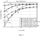
- the proposed Hard-SIC (MLM) scheme (i.e., plots 620 and 720) can be compared with the Hard-SIC (symbol equalization - SEQ) scheme based on MMSE equalization (i.e., plots 650 and 750). It can be observed significant throughput improvement of the proposed Hard-SIC MLM scheme.
- the iterative (i.e., soft) SIC based on MLM technique may further increase data throughput (i.e., plots 630 and 730). It can be also observed that similar throughput as in the case of Hard-SIC MLM scheme may be achieved if the MLM is applied without interference cancellation (i.e., plot 610 vs. 620 in FIG. 6 , and plot 710 vs. 720 in FIG. 7 ). However, error rate performance of the non-SIC MLM scheme is substantially worse compared to the Hard-SIC MLM scheme.
- the various operations of methods described above may be performed by any suitable means capable of performing the corresponding functions.
- the means may include various hardware and/or software component(s) and/or module(s), including, but not limited to a circuit, an application specific integrate circuit (ASIC), or processor.
- ASIC application specific integrate circuit
- blocks 510-550 illustrated in FIG. 5 correspond to circuit blocks 510A-550A illustrated in FIG. 5A .
- determining encompasses a wide variety of actions. For example, “determining” may include calculating, computing, processing, deriving, investigating, looking up (e.g., looking up in a table, a database or another data structure), ascertaining and the like. Also, “determining” may include receiving (e.g., receiving information), accessing (e.g., accessing data in a memory) and the like. Also, “determining” may include resolving, selecting, choosing, establishing and the like.
- any suitable means capable of performing the operations such as various hardware and/or software component(s), circuits, and/or module(s).
- any operations illustrated in the Figures may be performed by corresponding functional means capable of performing the operations.
- DSP digital signal processor
- ASIC application specific integrated circuit
- FPGA field programmable gate array signal
- PLD programmable logic device
- a general purpose processor may be a microprocessor, but in the alternative, the processor may be any commercially available processor, controller, microcontroller or state machine.
- a processor may also be implemented as a combination of computing devices, e.g., a combination of a DSP and a microprocessor, a plurality of microprocessors, one or more microprocessors in conjunction with a DSP core, or any other such configuration.
- a software module may reside in any form of storage medium that is known in the art. Some examples of storage media that may be used include random access memory (RAM), read only memory (ROM), flash memory, EPROM memory, EEPROM memory, registers, a hard disk, a removable disk, a CD-ROM and so forth.
- RAM random access memory
- ROM read only memory
- flash memory EPROM memory
- EEPROM memory EEPROM memory
- registers a hard disk, a removable disk, a CD-ROM and so forth.
- a software module may comprise a single instruction, or many instructions, and may be distributed over several different code segments, among different programs, and across multiple storage media.
- a storage medium may be coupled to a processor such that the processor can read information from, and write information to, the storage medium. In the alternative, the storage medium may be integral to the processor.
- the methods disclosed herein comprise one or more steps or actions for achieving the described method.
- the method steps and/or actions may be interchanged with one another without departing from the scope of the claims.
- the order and/or use of specific steps and/or actions may be modified without departing from the scope of the claims.
- a storage media may be any available media that can be accessed by a computer.
- such computer-readable media can comprise RAM, ROM, EEPROM, CD-ROM or other optical disk storage, magnetic disk storage or other magnetic storage devices, or any other medium that can be used to carry or store desired program code in the form of instructions or data structures and that can be accessed by a computer.
- Disk and disc include compact disc (CD), laser disc, optical disc, digital versatile disc (DVD), floppy disk, and Blu-ray® disc where disks usually reproduce data magnetically, while discs reproduce data optically with lasers.
- certain aspects may comprise a computer program product for performing the operations presented herein.
- a computer program product may comprise a computer readable medium having instructions stored (and/or encoded) thereon, the instructions being executable by one or more processors to perform the operations described herein.
- the computer program product may include packaging material.
- Software or instructions may also be transmitted over a transmission medium.
- a transmission medium For example, if the software is transmitted from a website, server, or other remote source using a coaxial cable, fiber optic cable, twisted pair, digital subscriber line (DSL), or wireless technologies such as infrared, radio, and microwave, then the coaxial cable, fiber optic cable, twisted pair, DSL, or wireless technologies such as infrared, radio, and microwave are included in the definition of transmission medium.
- DSL digital subscriber line
- modules and/or other appropriate means for performing the methods and techniques described herein can be downloaded and/or otherwise obtained by a user terminal and/or base station as applicable.
- a user terminal and/or base station can be coupled to a server to facilitate the transfer of means for performing the methods described herein.
- various methods described herein can be provided via storage means (e.g., RAM, ROM, a physical storage medium such as a compact disc (CD) or floppy disk, etc.), such that a user terminal and/or base station can obtain the various methods upon coupling or providing the storage means to the device.
- storage means e.g., RAM, ROM, a physical storage medium such as a compact disc (CD) or floppy disk, etc.
- CD compact disc
- floppy disk etc.
- any other suitable technique for providing the methods and techniques described herein to a device can be utilized.
- the techniques provided herein may be utilized in a variety of applications.
- the techniques presented herein may be incorporated in an access point station, an access terminal, or other type of wireless device with processing logic and elements to perform the techniques provided herein.
Landscapes
- Engineering & Computer Science (AREA)
- Computer Networks & Wireless Communication (AREA)
- Signal Processing (AREA)
- Radio Transmission System (AREA)
- Artificial Intelligence (AREA)
- Quality & Reliability (AREA)
- Error Detection And Correction (AREA)
Applications Claiming Priority (2)
| Application Number | Priority Date | Filing Date | Title |
|---|---|---|---|
| US12/552,647 US8989320B2 (en) | 2009-09-02 | 2009-09-02 | Hardware simplification of sic-MIMO decoding by use of a single hardware element with channel and noise adaptation for interference cancelled streams |
| PCT/US2010/047724 WO2011028936A1 (en) | 2009-09-02 | 2010-09-02 | Hardware simplification of sic-mimo decoding by use of a single hardware element with channel and noise adaptation for interference cancelled streams |
Publications (2)
| Publication Number | Publication Date |
|---|---|
| EP2474117A1 EP2474117A1 (en) | 2012-07-11 |
| EP2474117B1 true EP2474117B1 (en) | 2018-10-17 |
Family
ID=43500202
Family Applications (1)
| Application Number | Title | Priority Date | Filing Date |
|---|---|---|---|
| EP10752973.7A Not-in-force EP2474117B1 (en) | 2009-09-02 | 2010-09-02 | Hardware simplification of sic-mimo decoding by use of a single hardware element with channel and noise adaptation for interference cancelled streams |
Country Status (6)
| Country | Link |
|---|---|
| US (1) | US8989320B2 (enExample) |
| EP (1) | EP2474117B1 (enExample) |
| JP (1) | JP5437491B2 (enExample) |
| KR (1) | KR101333222B1 (enExample) |
| CN (1) | CN102484563B (enExample) |
| WO (1) | WO2011028936A1 (enExample) |
Families Citing this family (28)
| Publication number | Priority date | Publication date | Assignee | Title |
|---|---|---|---|---|
| US8514984B2 (en) * | 2009-09-02 | 2013-08-20 | Qualcomm Incorporated | Iterative decoding architecture with HARQ combining and soft decision directed channel estimation |
| US8976903B2 (en) * | 2009-09-02 | 2015-03-10 | Qualcomm Incorporated | Unified iterative decoding architecture using joint LLR extraction and a priori probability |
| EP2293504B1 (en) * | 2009-09-04 | 2014-06-18 | Intel Mobile Communications GmbH | Method and apparatus for interference mitigation in a baseband OFDM receiver |
| US8199034B2 (en) | 2010-04-20 | 2012-06-12 | Qualcomm Incorporated | Method and apparatus for soft symbol determination |
| US8687750B1 (en) * | 2010-06-25 | 2014-04-01 | Marvell International Ltd. | Signal detection with adjustable number of interfering signals |
| IL207180A (en) | 2010-07-25 | 2016-03-31 | Elta Systems Ltd | A system for switching application processors in cellular systems |
| JP5721486B2 (ja) * | 2011-03-18 | 2015-05-20 | 株式会社日立国際電気 | 通信機 |
| EP2597797B1 (en) | 2011-11-25 | 2017-07-26 | Sequans Communications | Interference cancellation method with multiple data layer MIMO transmission |
| US20130156139A1 (en) * | 2011-12-15 | 2013-06-20 | Samsung Electronics Co., Ltd. | Wireless communication system with interference filtering and method of operation thereof |
| US9264266B2 (en) * | 2011-12-29 | 2016-02-16 | Intel Corporation | Successive interference cancellation system and method for MIMO horizontal encoding and decoding |
| US8761317B2 (en) * | 2012-04-04 | 2014-06-24 | Telefonaktiebolaget L M Ericsson (Publ) | Soft-bit generation and channel estimation for interference cancellation using decoder output |
| GB2501901A (en) * | 2012-05-09 | 2013-11-13 | Renesas Mobile Corp | Simultaneous use of multiple receivers with different operation parameters or logic |
| US8724754B2 (en) | 2012-08-29 | 2014-05-13 | Motorola Mobility Llc | Noise power thresholding and balancing for long term evolution (LTE) symbol detection |
| US9313059B2 (en) * | 2012-12-21 | 2016-04-12 | Qualcomm Incorporated | Data-modulated pilots for phase and gain detectors |
| US9172413B2 (en) | 2013-02-08 | 2015-10-27 | Mediatek Inc. | Method and apparatus for performing wireless communications with aid of successive data processing in multiple iterations |
| CN104160643A (zh) * | 2013-03-11 | 2014-11-19 | 华为技术有限公司 | 迭代式干扰消除方法 |
| US9197267B2 (en) | 2013-04-09 | 2015-11-24 | Qualcomm Incorporated | Methods and apparatus for joint demodulation with max-log MAP (MLM) |
| US9806827B2 (en) * | 2013-09-13 | 2017-10-31 | Samsung Electronics Co., Ltd. | Computing system with interference cancellation mechanism and method of operation thereof |
| EP3090501B1 (en) * | 2013-12-30 | 2019-06-12 | Telecom Italia S.p.A. | Improved receiver for wireless communications networks |
| WO2015113251A1 (zh) * | 2014-01-29 | 2015-08-06 | 华为技术有限公司 | 干扰抑制方法与装置 |
| US10205470B2 (en) * | 2014-02-14 | 2019-02-12 | Samsung Electronics Co., Ltd | System and methods for low complexity list decoding of turbo codes and convolutional codes |
| EP3059914B1 (en) * | 2015-02-18 | 2018-08-08 | Mitsubishi Electric R&D Centre Europe B.V. | Method and a device for computing a soft estimate of coded bits forming transmitted symbol vectors |
| CN106160831B (zh) * | 2015-03-23 | 2019-09-17 | 电信科学技术研究院 | 一种信号检测方法及装置 |
| EP3226497B1 (en) * | 2016-03-30 | 2018-06-06 | Intel Corporation | Initial layer selection in successive interference cancelation systems |
| US10536239B2 (en) | 2016-12-14 | 2020-01-14 | Samsung Electronics Co., Ltd | Soft channel tracking using detection output |
| US10237025B2 (en) * | 2017-02-03 | 2019-03-19 | At&T Intellectual Property I, L.P. | Detecting data in multiantenna wireless communication systems |
| US10686508B2 (en) * | 2018-08-10 | 2020-06-16 | At&T Intellectual Property I, L.P. | Multiple-input multiple-output system performance using advanced receivers for 5G or other next generation networks |
| US20240129062A1 (en) * | 2022-09-30 | 2024-04-18 | Hughes Network Systems, Llc | Iterative Mitigation of Nonlinear Co-Channel Interference in High-Efficiency Multibeam Satellite Systems |
Family Cites Families (39)
| Publication number | Priority date | Publication date | Assignee | Title |
|---|---|---|---|---|
| KR100557177B1 (ko) * | 1998-04-04 | 2006-07-21 | 삼성전자주식회사 | 적응 채널 부호/복호화 방법 및 그 부호/복호 장치 |
| DE69839625D1 (de) | 1998-08-21 | 2008-07-31 | Lucent Technologies Inc | Mehrfachkode CDMA-System unter Verwendung von iterativer Dekodierung |
| US6014411A (en) | 1998-10-29 | 2000-01-11 | The Aerospace Corporation | Repetitive turbo coding communication method |
| WO2001005059A1 (en) | 1999-07-08 | 2001-01-18 | Samsung Electronics Co., Ltd. | Apparatus and method for controlling a demultiplexer and a multiplexer used for rate matching in a mobile communication system |
| WO2001019013A1 (en) | 1999-09-09 | 2001-03-15 | Home Wireless Networks, Inc. | Turbo detection of space-time codes |
| KR100713331B1 (ko) | 2000-12-23 | 2007-05-04 | 삼성전자주식회사 | 부호분할다중접속 이동통신시스템의 반복복호 중지 장치 및 방법 |
| EP1249958B1 (de) * | 2001-04-09 | 2005-01-19 | Alcatel | Verfahren und Vorrichtung zur adaptiven Turbo Dekodierung mehrerer Funkkanäle unter Bestimmung eines CRC am Ende jeder Iteration |
| KR100444571B1 (ko) * | 2002-01-11 | 2004-08-16 | 삼성전자주식회사 | 터보디코더와 알에스디코더가 연접된 디코딩장치 및 그의디코딩방법 |
| US7093180B2 (en) | 2002-06-28 | 2006-08-15 | Interdigital Technology Corporation | Fast H-ARQ acknowledgement generation method using a stopping rule for turbo decoding |
| US7653858B2 (en) | 2002-12-20 | 2010-01-26 | Nokia Corporation | Low complexity decoding schemes for single-parity-check (SPC) based concatenated codes |
| WO2004095713A2 (en) * | 2003-04-14 | 2004-11-04 | Bae Systems Information And Electronic Systems Integration Inc. | Joint symbol, amplitude, and rate estimator |
| US7376209B2 (en) * | 2003-06-06 | 2008-05-20 | Qualcomm Incorporated | Method and apparatus for near-optimal scaling of log-likelihood ratio (LLR) computation in turbo decoding for hybrid automatic repeat request (ARQ) |
| US8325863B2 (en) * | 2004-10-12 | 2012-12-04 | Qualcomm Incorporated | Data detection and decoding with considerations for channel estimation errors due to guard subbands |
| US7590195B2 (en) * | 2005-02-23 | 2009-09-15 | Nec Laboratories America, Inc. | Reduced-complexity multiple-input multiple-output (MIMO) channel detection via sequential Monte Carlo |
| JP2006246341A (ja) | 2005-03-07 | 2006-09-14 | Matsushita Electric Ind Co Ltd | 通信装置、送信装置、復調方法及び通信方法 |
| JP4841615B2 (ja) | 2005-03-14 | 2011-12-21 | テルコーディア ライセンシング カンパニー, リミテッド ライアビリティ カンパニー | グループ単位のデマッピングを用いる繰り返しmimo受信機 |
| CN1838582A (zh) | 2005-03-24 | 2006-09-27 | 松下电器产业株式会社 | 利用信道分解的自动重传请求方法、及发送/接收处理单元 |
| JP2007006382A (ja) | 2005-06-27 | 2007-01-11 | Matsushita Electric Ind Co Ltd | 受信装置および反復復号方法 |
| KR101124863B1 (ko) * | 2005-07-20 | 2012-03-27 | 에스티마이크로일렉트로닉스 에스.알.엘. | 다중 소스로부터의 통신신호를 처리하는 장치 및 방법 |
| KR100842583B1 (ko) * | 2005-11-21 | 2008-07-01 | 삼성전자주식회사 | 통신 시스템에서 데이터 수신 방법 및 장치 |
| KR100923915B1 (ko) * | 2005-12-16 | 2009-10-28 | 삼성전자주식회사 | 다중 안테나 시스템에서 반복 검출 및 복호 수신 장치 및방법 |
| US8804885B2 (en) * | 2005-12-19 | 2014-08-12 | Agere Systems Llc | Delay compensation in equalizer-based receiver |
| TW201025894A (en) | 2006-02-10 | 2010-07-01 | Interdigital Tech Corp | Method and apparatus for performing uplink transmission in a multiple-input multiple-output single carrier frequency division multiple access system |
| KR20080102393A (ko) | 2006-02-17 | 2008-11-25 | 노키아 코포레이션 | Aimo 수신기를 제공하는 장치, 방법 및 컴퓨터 프로그램 생성물 |
| US7792084B2 (en) * | 2006-08-29 | 2010-09-07 | Panasonic Corporation | MIMO antenna apparatus controlling number of streams and modulation and demodulation method |
| JP4827695B2 (ja) | 2006-11-13 | 2011-11-30 | パナソニック株式会社 | 無線受信装置 |
| CN201018490Y (zh) | 2007-01-04 | 2008-02-06 | 浙江华立通信集团有限公司 | TD-SCDMA/3G硬核turbo译码器 |
| JP2008306318A (ja) * | 2007-06-05 | 2008-12-18 | Toshiba Corp | 無線受信装置、無線受信装置の制御方法、無線受信装置の制御プログラム、および半導体集積回路 |
| US20090031185A1 (en) * | 2007-07-23 | 2009-01-29 | Texas Instruments Incorporated | Hybrid arq systems and methods for packet-based networks |
| JP2009055228A (ja) * | 2007-08-24 | 2009-03-12 | Sony Corp | 無線通信システム、無線通信装置及び無線通信方法 |
| CN101183919B (zh) | 2007-11-26 | 2011-09-14 | 华中科技大学 | 一种组合的混合自动请求重传方法 |
| US20110007729A1 (en) * | 2008-02-21 | 2011-01-13 | Toshizo Nogami | Reception device, transmission device, communication system, and communication method |
| TW200943757A (en) * | 2008-04-08 | 2009-10-16 | Ralink Technology Corp | Iterative signal receiving method and related iterative receiver |
| GB2459939B (en) * | 2008-05-16 | 2012-02-15 | Icera Inc | Fetching descriptors in a multiple context DMA engine |
| US8601355B2 (en) * | 2008-05-28 | 2013-12-03 | Texas Instruments Incorporated | System and method for determining parity bit soft information at a turbo decoder output |
| US8565329B2 (en) * | 2008-06-03 | 2013-10-22 | Ntt Docomo, Inc. | Soft output M-algorithm receiver structures with generalized survivor selection criteria for MIMO systems |
| US8976903B2 (en) * | 2009-09-02 | 2015-03-10 | Qualcomm Incorporated | Unified iterative decoding architecture using joint LLR extraction and a priori probability |
| US8514984B2 (en) * | 2009-09-02 | 2013-08-20 | Qualcomm Incorporated | Iterative decoding architecture with HARQ combining and soft decision directed channel estimation |
| US8199034B2 (en) * | 2010-04-20 | 2012-06-12 | Qualcomm Incorporated | Method and apparatus for soft symbol determination |
-
2009
- 2009-09-02 US US12/552,647 patent/US8989320B2/en active Active
-
2010
- 2010-09-02 EP EP10752973.7A patent/EP2474117B1/en not_active Not-in-force
- 2010-09-02 KR KR1020127008563A patent/KR101333222B1/ko not_active Expired - Fee Related
- 2010-09-02 CN CN201080039077.XA patent/CN102484563B/zh not_active Expired - Fee Related
- 2010-09-02 WO PCT/US2010/047724 patent/WO2011028936A1/en not_active Ceased
- 2010-09-02 JP JP2012528060A patent/JP5437491B2/ja not_active Expired - Fee Related
Non-Patent Citations (1)
| Title |
|---|
| None * |
Also Published As
| Publication number | Publication date |
|---|---|
| US20110051858A1 (en) | 2011-03-03 |
| KR101333222B1 (ko) | 2013-11-26 |
| EP2474117A1 (en) | 2012-07-11 |
| KR20120054086A (ko) | 2012-05-29 |
| WO2011028936A1 (en) | 2011-03-10 |
| JP5437491B2 (ja) | 2014-03-12 |
| JP2013504261A (ja) | 2013-02-04 |
| CN102484563B (zh) | 2014-07-30 |
| CN102484563A (zh) | 2012-05-30 |
| US8989320B2 (en) | 2015-03-24 |
Similar Documents
| Publication | Publication Date | Title |
|---|---|---|
| EP2474117B1 (en) | Hardware simplification of sic-mimo decoding by use of a single hardware element with channel and noise adaptation for interference cancelled streams | |
| KR101458009B1 (ko) | Harq 결합 및 소프트 판정 지시 채널 추정을 통한 반복 디코딩 아키텍처 | |
| US8976903B2 (en) | Unified iterative decoding architecture using joint LLR extraction and a priori probability | |
| JP2013504261A5 (enExample) | ||
| KR101301189B1 (ko) | 연속하는 간섭 소거를 이용하여 mimo 시스템에서 디코딩 순서를 결정하기 위한 방법들 | |
| US8391429B2 (en) | Methods for determining reconstruction weights in a MIMO system with successive interference cancellation | |
| EP3621208B1 (en) | Efficient frequency domain (fd) mmse equalization weight updates in a multi-stage parallel interference cancellation receiver | |
| WO2010033437A2 (en) | Methods and systems for maximum-likelihood detection using post-squaring compensation | |
| US20100091912A1 (en) | Methods and systems using norm approximation for maximum likelihood mimo decoding | |
| US7907688B2 (en) | Open loop MIMO receiver and method using hard decision feedback | |
| EP1811706B1 (en) | Method and system for an improved cellular interference cancelling diversity receiver |
Legal Events
| Date | Code | Title | Description |
|---|---|---|---|
| PUAI | Public reference made under article 153(3) epc to a published international application that has entered the european phase |
Free format text: ORIGINAL CODE: 0009012 |
|
| 17P | Request for examination filed |
Effective date: 20120330 |
|
| AK | Designated contracting states |
Kind code of ref document: A1 Designated state(s): AL AT BE BG CH CY CZ DE DK EE ES FI FR GB GR HR HU IE IS IT LI LT LU LV MC MK MT NL NO PL PT RO SE SI SK SM TR |
|
| DAX | Request for extension of the european patent (deleted) | ||
| STAA | Information on the status of an ep patent application or granted ep patent |
Free format text: STATUS: EXAMINATION IS IN PROGRESS |
|
| 17Q | First examination report despatched |
Effective date: 20161125 |
|
| GRAP | Despatch of communication of intention to grant a patent |
Free format text: ORIGINAL CODE: EPIDOSNIGR1 |
|
| STAA | Information on the status of an ep patent application or granted ep patent |
Free format text: STATUS: GRANT OF PATENT IS INTENDED |
|
| INTG | Intention to grant announced |
Effective date: 20180504 |
|
| RIN1 | Information on inventor provided before grant (corrected) |
Inventor name: TANG, JIA Inventor name: PARK, JONG HYEON Inventor name: SALVEKAR, ATUL A. Inventor name: KHARE, SHANTANU |
|
| GRAS | Grant fee paid |
Free format text: ORIGINAL CODE: EPIDOSNIGR3 |
|
| GRAA | (expected) grant |
Free format text: ORIGINAL CODE: 0009210 |
|
| STAA | Information on the status of an ep patent application or granted ep patent |
Free format text: STATUS: THE PATENT HAS BEEN GRANTED |
|
| AK | Designated contracting states |
Kind code of ref document: B1 Designated state(s): AL AT BE BG CH CY CZ DE DK EE ES FI FR GB GR HR HU IE IS IT LI LT LU LV MC MK MT NL NO PL PT RO SE SI SK SM TR |
|
| REG | Reference to a national code |
Ref country code: GB Ref legal event code: FG4D |
|
| REG | Reference to a national code |
Ref country code: CH Ref legal event code: EP |
|
| REG | Reference to a national code |
Ref country code: IE Ref legal event code: FG4D |
|
| REG | Reference to a national code |
Ref country code: DE Ref legal event code: R096 Ref document number: 602010054410 Country of ref document: DE Ref country code: AT Ref legal event code: REF Ref document number: 1055261 Country of ref document: AT Kind code of ref document: T Effective date: 20181115 |
|
| REG | Reference to a national code |
Ref country code: NL Ref legal event code: MP Effective date: 20181017 |
|
| REG | Reference to a national code |
Ref country code: LT Ref legal event code: MG4D |
|
| REG | Reference to a national code |
Ref country code: AT Ref legal event code: MK05 Ref document number: 1055261 Country of ref document: AT Kind code of ref document: T Effective date: 20181017 |
|
| PG25 | Lapsed in a contracting state [announced via postgrant information from national office to epo] |
Ref country code: NL Free format text: LAPSE BECAUSE OF FAILURE TO SUBMIT A TRANSLATION OF THE DESCRIPTION OR TO PAY THE FEE WITHIN THE PRESCRIBED TIME-LIMIT Effective date: 20181017 |
|
| PG25 | Lapsed in a contracting state [announced via postgrant information from national office to epo] |
Ref country code: IS Free format text: LAPSE BECAUSE OF FAILURE TO SUBMIT A TRANSLATION OF THE DESCRIPTION OR TO PAY THE FEE WITHIN THE PRESCRIBED TIME-LIMIT Effective date: 20190217 Ref country code: HR Free format text: LAPSE BECAUSE OF FAILURE TO SUBMIT A TRANSLATION OF THE DESCRIPTION OR TO PAY THE FEE WITHIN THE PRESCRIBED TIME-LIMIT Effective date: 20181017 Ref country code: PL Free format text: LAPSE BECAUSE OF FAILURE TO SUBMIT A TRANSLATION OF THE DESCRIPTION OR TO PAY THE FEE WITHIN THE PRESCRIBED TIME-LIMIT Effective date: 20181017 Ref country code: NO Free format text: LAPSE BECAUSE OF FAILURE TO SUBMIT A TRANSLATION OF THE DESCRIPTION OR TO PAY THE FEE WITHIN THE PRESCRIBED TIME-LIMIT Effective date: 20190117 Ref country code: BG Free format text: LAPSE BECAUSE OF FAILURE TO SUBMIT A TRANSLATION OF THE DESCRIPTION OR TO PAY THE FEE WITHIN THE PRESCRIBED TIME-LIMIT Effective date: 20190117 Ref country code: LT Free format text: LAPSE BECAUSE OF FAILURE TO SUBMIT A TRANSLATION OF THE DESCRIPTION OR TO PAY THE FEE WITHIN THE PRESCRIBED TIME-LIMIT Effective date: 20181017 Ref country code: ES Free format text: LAPSE BECAUSE OF FAILURE TO SUBMIT A TRANSLATION OF THE DESCRIPTION OR TO PAY THE FEE WITHIN THE PRESCRIBED TIME-LIMIT Effective date: 20181017 Ref country code: LV Free format text: LAPSE BECAUSE OF FAILURE TO SUBMIT A TRANSLATION OF THE DESCRIPTION OR TO PAY THE FEE WITHIN THE PRESCRIBED TIME-LIMIT Effective date: 20181017 Ref country code: AT Free format text: LAPSE BECAUSE OF FAILURE TO SUBMIT A TRANSLATION OF THE DESCRIPTION OR TO PAY THE FEE WITHIN THE PRESCRIBED TIME-LIMIT Effective date: 20181017 Ref country code: FI Free format text: LAPSE BECAUSE OF FAILURE TO SUBMIT A TRANSLATION OF THE DESCRIPTION OR TO PAY THE FEE WITHIN THE PRESCRIBED TIME-LIMIT Effective date: 20181017 |
|
| PG25 | Lapsed in a contracting state [announced via postgrant information from national office to epo] |
Ref country code: PT Free format text: LAPSE BECAUSE OF FAILURE TO SUBMIT A TRANSLATION OF THE DESCRIPTION OR TO PAY THE FEE WITHIN THE PRESCRIBED TIME-LIMIT Effective date: 20190217 Ref country code: SE Free format text: LAPSE BECAUSE OF FAILURE TO SUBMIT A TRANSLATION OF THE DESCRIPTION OR TO PAY THE FEE WITHIN THE PRESCRIBED TIME-LIMIT Effective date: 20181017 Ref country code: AL Free format text: LAPSE BECAUSE OF FAILURE TO SUBMIT A TRANSLATION OF THE DESCRIPTION OR TO PAY THE FEE WITHIN THE PRESCRIBED TIME-LIMIT Effective date: 20181017 Ref country code: GR Free format text: LAPSE BECAUSE OF FAILURE TO SUBMIT A TRANSLATION OF THE DESCRIPTION OR TO PAY THE FEE WITHIN THE PRESCRIBED TIME-LIMIT Effective date: 20190118 |
|
| REG | Reference to a national code |
Ref country code: DE Ref legal event code: R097 Ref document number: 602010054410 Country of ref document: DE |
|
| PG25 | Lapsed in a contracting state [announced via postgrant information from national office to epo] |
Ref country code: IT Free format text: LAPSE BECAUSE OF FAILURE TO SUBMIT A TRANSLATION OF THE DESCRIPTION OR TO PAY THE FEE WITHIN THE PRESCRIBED TIME-LIMIT Effective date: 20181017 Ref country code: DK Free format text: LAPSE BECAUSE OF FAILURE TO SUBMIT A TRANSLATION OF THE DESCRIPTION OR TO PAY THE FEE WITHIN THE PRESCRIBED TIME-LIMIT Effective date: 20181017 Ref country code: CZ Free format text: LAPSE BECAUSE OF FAILURE TO SUBMIT A TRANSLATION OF THE DESCRIPTION OR TO PAY THE FEE WITHIN THE PRESCRIBED TIME-LIMIT Effective date: 20181017 |
|
| PLBE | No opposition filed within time limit |
Free format text: ORIGINAL CODE: 0009261 |
|
| STAA | Information on the status of an ep patent application or granted ep patent |
Free format text: STATUS: NO OPPOSITION FILED WITHIN TIME LIMIT |
|
| PG25 | Lapsed in a contracting state [announced via postgrant information from national office to epo] |
Ref country code: RO Free format text: LAPSE BECAUSE OF FAILURE TO SUBMIT A TRANSLATION OF THE DESCRIPTION OR TO PAY THE FEE WITHIN THE PRESCRIBED TIME-LIMIT Effective date: 20181017 Ref country code: SK Free format text: LAPSE BECAUSE OF FAILURE TO SUBMIT A TRANSLATION OF THE DESCRIPTION OR TO PAY THE FEE WITHIN THE PRESCRIBED TIME-LIMIT Effective date: 20181017 Ref country code: SM Free format text: LAPSE BECAUSE OF FAILURE TO SUBMIT A TRANSLATION OF THE DESCRIPTION OR TO PAY THE FEE WITHIN THE PRESCRIBED TIME-LIMIT Effective date: 20181017 Ref country code: EE Free format text: LAPSE BECAUSE OF FAILURE TO SUBMIT A TRANSLATION OF THE DESCRIPTION OR TO PAY THE FEE WITHIN THE PRESCRIBED TIME-LIMIT Effective date: 20181017 |
|
| 26N | No opposition filed |
Effective date: 20190718 |
|
| PG25 | Lapsed in a contracting state [announced via postgrant information from national office to epo] |
Ref country code: SI Free format text: LAPSE BECAUSE OF FAILURE TO SUBMIT A TRANSLATION OF THE DESCRIPTION OR TO PAY THE FEE WITHIN THE PRESCRIBED TIME-LIMIT Effective date: 20181017 |
|
| PG25 | Lapsed in a contracting state [announced via postgrant information from national office to epo] |
Ref country code: TR Free format text: LAPSE BECAUSE OF FAILURE TO SUBMIT A TRANSLATION OF THE DESCRIPTION OR TO PAY THE FEE WITHIN THE PRESCRIBED TIME-LIMIT Effective date: 20181017 |
|
| PG25 | Lapsed in a contracting state [announced via postgrant information from national office to epo] |
Ref country code: MC Free format text: LAPSE BECAUSE OF FAILURE TO SUBMIT A TRANSLATION OF THE DESCRIPTION OR TO PAY THE FEE WITHIN THE PRESCRIBED TIME-LIMIT Effective date: 20181017 |
|
| REG | Reference to a national code |
Ref country code: CH Ref legal event code: PL |
|
| PG25 | Lapsed in a contracting state [announced via postgrant information from national office to epo] |
Ref country code: CH Free format text: LAPSE BECAUSE OF NON-PAYMENT OF DUE FEES Effective date: 20190930 Ref country code: IE Free format text: LAPSE BECAUSE OF NON-PAYMENT OF DUE FEES Effective date: 20190902 Ref country code: LI Free format text: LAPSE BECAUSE OF NON-PAYMENT OF DUE FEES Effective date: 20190930 Ref country code: LU Free format text: LAPSE BECAUSE OF NON-PAYMENT OF DUE FEES Effective date: 20190902 |
|
| REG | Reference to a national code |
Ref country code: BE Ref legal event code: MM Effective date: 20190930 |
|
| PG25 | Lapsed in a contracting state [announced via postgrant information from national office to epo] |
Ref country code: BE Free format text: LAPSE BECAUSE OF NON-PAYMENT OF DUE FEES Effective date: 20190930 |
|
| PG25 | Lapsed in a contracting state [announced via postgrant information from national office to epo] |
Ref country code: CY Free format text: LAPSE BECAUSE OF FAILURE TO SUBMIT A TRANSLATION OF THE DESCRIPTION OR TO PAY THE FEE WITHIN THE PRESCRIBED TIME-LIMIT Effective date: 20181017 |
|
| PG25 | Lapsed in a contracting state [announced via postgrant information from national office to epo] |
Ref country code: HU Free format text: LAPSE BECAUSE OF FAILURE TO SUBMIT A TRANSLATION OF THE DESCRIPTION OR TO PAY THE FEE WITHIN THE PRESCRIBED TIME-LIMIT; INVALID AB INITIO Effective date: 20100902 Ref country code: MT Free format text: LAPSE BECAUSE OF FAILURE TO SUBMIT A TRANSLATION OF THE DESCRIPTION OR TO PAY THE FEE WITHIN THE PRESCRIBED TIME-LIMIT Effective date: 20181017 |
|
| PG25 | Lapsed in a contracting state [announced via postgrant information from national office to epo] |
Ref country code: MK Free format text: LAPSE BECAUSE OF FAILURE TO SUBMIT A TRANSLATION OF THE DESCRIPTION OR TO PAY THE FEE WITHIN THE PRESCRIBED TIME-LIMIT Effective date: 20181017 |
|
| PGFP | Annual fee paid to national office [announced via postgrant information from national office to epo] |
Ref country code: GB Payment date: 20230810 Year of fee payment: 14 |
|
| PGFP | Annual fee paid to national office [announced via postgrant information from national office to epo] |
Ref country code: FR Payment date: 20230808 Year of fee payment: 14 Ref country code: DE Payment date: 20230808 Year of fee payment: 14 |
|
| REG | Reference to a national code |
Ref country code: DE Ref legal event code: R119 Ref document number: 602010054410 Country of ref document: DE |
|
| GBPC | Gb: european patent ceased through non-payment of renewal fee |
Effective date: 20240902 |
|
| PG25 | Lapsed in a contracting state [announced via postgrant information from national office to epo] |
Ref country code: DE Free format text: LAPSE BECAUSE OF NON-PAYMENT OF DUE FEES Effective date: 20250401 |
|
| PG25 | Lapsed in a contracting state [announced via postgrant information from national office to epo] |
Ref country code: GB Free format text: LAPSE BECAUSE OF NON-PAYMENT OF DUE FEES Effective date: 20240902 |
|
| PG25 | Lapsed in a contracting state [announced via postgrant information from national office to epo] |
Ref country code: FR Free format text: LAPSE BECAUSE OF NON-PAYMENT OF DUE FEES Effective date: 20240930 |