EP2473419B1 - Verschliessbare kappe für eine flasche - Google Patents
Verschliessbare kappe für eine flasche Download PDFInfo
- Publication number
- EP2473419B1 EP2473419B1 EP20100814459 EP10814459A EP2473419B1 EP 2473419 B1 EP2473419 B1 EP 2473419B1 EP 20100814459 EP20100814459 EP 20100814459 EP 10814459 A EP10814459 A EP 10814459A EP 2473419 B1 EP2473419 B1 EP 2473419B1
- Authority
- EP
- European Patent Office
- Prior art keywords
- cap
- plate
- locking plate
- housing
- cogs
- Prior art date
- Legal status (The legal status is an assumption and is not a legal conclusion. Google has not performed a legal analysis and makes no representation as to the accuracy of the status listed.)
- Active
Links
Images


Classifications
-
- B—PERFORMING OPERATIONS; TRANSPORTING
- B65—CONVEYING; PACKING; STORING; HANDLING THIN OR FILAMENTARY MATERIAL
- B65D—CONTAINERS FOR STORAGE OR TRANSPORT OF ARTICLES OR MATERIALS, e.g. BAGS, BARRELS, BOTTLES, BOXES, CANS, CARTONS, CRATES, DRUMS, JARS, TANKS, HOPPERS, FORWARDING CONTAINERS; ACCESSORIES, CLOSURES, OR FITTINGS THEREFOR; PACKAGING ELEMENTS; PACKAGES
- B65D55/00—Accessories for container closures not otherwise provided for
- B65D55/02—Locking devices; Means for discouraging or indicating unauthorised opening or removal of closure
- B65D55/14—Applications of locks, e.g. of permutation or key-controlled locks
- B65D55/145—Applications of locks, e.g. of permutation or key-controlled locks of permutation locks
-
- B—PERFORMING OPERATIONS; TRANSPORTING
- B65—CONVEYING; PACKING; STORING; HANDLING THIN OR FILAMENTARY MATERIAL
- B65D—CONTAINERS FOR STORAGE OR TRANSPORT OF ARTICLES OR MATERIALS, e.g. BAGS, BARRELS, BOTTLES, BOXES, CANS, CARTONS, CRATES, DRUMS, JARS, TANKS, HOPPERS, FORWARDING CONTAINERS; ACCESSORIES, CLOSURES, OR FITTINGS THEREFOR; PACKAGING ELEMENTS; PACKAGES
- B65D43/00—Lids or covers for rigid or semi-rigid containers
- B65D43/14—Non-removable lids or covers
- B65D43/16—Non-removable lids or covers hinged for upward or downward movement
-
- Y—GENERAL TAGGING OF NEW TECHNOLOGICAL DEVELOPMENTS; GENERAL TAGGING OF CROSS-SECTIONAL TECHNOLOGIES SPANNING OVER SEVERAL SECTIONS OF THE IPC; TECHNICAL SUBJECTS COVERED BY FORMER USPC CROSS-REFERENCE ART COLLECTIONS [XRACs] AND DIGESTS
- Y10—TECHNICAL SUBJECTS COVERED BY FORMER USPC
- Y10T—TECHNICAL SUBJECTS COVERED BY FORMER US CLASSIFICATION
- Y10T29/00—Metal working
- Y10T29/49—Method of mechanical manufacture
- Y10T29/49826—Assembling or joining
-
- Y—GENERAL TAGGING OF NEW TECHNOLOGICAL DEVELOPMENTS; GENERAL TAGGING OF CROSS-SECTIONAL TECHNOLOGIES SPANNING OVER SEVERAL SECTIONS OF THE IPC; TECHNICAL SUBJECTS COVERED BY FORMER USPC CROSS-REFERENCE ART COLLECTIONS [XRACs] AND DIGESTS
- Y10—TECHNICAL SUBJECTS COVERED BY FORMER USPC
- Y10T—TECHNICAL SUBJECTS COVERED BY FORMER US CLASSIFICATION
- Y10T70/00—Locks
- Y10T70/50—Special application
- Y10T70/5093—For closures
- Y10T70/554—Cover, lid, cap, encasing shield
Definitions
- the disclosure relates generally to a cap lock attachable to a bottle and in particular to a medical prescription bottle, and to a method of manufacturing said cap lock.
- Document US 4,829,796 relates to an apparatus for keeping a spare key in the car. Only when the numbers of the revolving rings are set to the predetermined numbers, a spare key can be taken out because the cap of the apparatus is released from an inlet of the fuel tank. Although a driver has lost his car key or locks the door with his key being left in the car or he does not have a key, he can drive his car by utilization of a spare key which is installed under the fuel tank cap. In case his secret number for the spare key is known to others, he can easily change the number to a new number.
- the disclosure is particularly applicable to a prescription medical bottle and it is in this context that the disclosure will be described. It will be appreciated, however, that the device has greater utility since the device can be used with various other types of bottles or containers in which it is desirable to be able to securely lock the bottle/containers from unauthorized use.
- a first embodiment of the device puts a combination dial lock of FIG. 1 onto a bottle 90 of FIG. 2 .
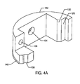
- the lower portion of the design contains the dog plate shown in FIG. 4A .
- the inner portion of the dog plate is threaded as at 157 shown in FIG. 5B in order to twist onto a common prescription bottle 90.
- the dog plate of FIG. 5A has a flat circular set of gear teeth of which 148 in an example.
- Each large and durable tooth surface 154 allows for a single point of contact to exert enough tension to apply and remove the cap.
- These teeth are set away from the side wall with a gap 146 that gap allows the dog plate to spin freely within housing 100 at 176 of FIG. 3 and of FIG. 7B .
- Above the dog plate is the dial lock shown in FIG. 1 .
- the dial lock is of a well known type. As seen in FIG. 2 , this set of dial lock wheels contains both numeric cogs 92 and the standard cams 94a, 94b, and 94c. The cams are spring held into the numeric cogs. The shape of the cams illustrates what movements are possible, all of the cams have one flat secant section removed 99. These flat sections on the cams work in unison with each other, only when all the flat sections of the cams line up will the unit become unlocked. These wheels both spin on the dowel pin axle 86, and are held in place with a spring 84 on the far left of dowel pin axle. Above the dials is the lock plate 122 of FIG.
- This moving part shown at 122 connects and disconnects from the dog plate 156 of FIG. 2 and of FIG. 5A .
- This is also the component that allows the system to be reset. Only when the locking plate is down (unlocked) 114 can the user reset the dials to their personal combination.
- the bottle locking device is controlled by a horizontal tamper resistant outlet. The combination is reset using a specific lengthened pin 93 that is designed to offset the numeric cogs 92 from the large cams 94a, 94b, and 94c.
- Surrounding the large locking plate and the dials are the alignment spacers seen in FIG. 5A and FIG. 4B .
- the left alignment spacer seen in FIG. 4A and the right alignment spacer seen in FIG. 4B act to stabilize the dowel pin axle 86 as seen in FIG. 2 and holds the inner components of the bottle locking device in place.
- the right alignment spacer has an additive access outlet 144. Surrounding all of the component is the housing 100.
- This bottle locking device is based on an idea of a gear slipping device.
- the locking plate 122 in FIG. 2 and FIG. 3A that sits on the cams 94a-c is rotated into the flat position.
- the lock plate With this cam position shown at 99 of FIG. 2 , the lock plate is in the down position making the connection between the lock plate of FIG. 3B at 126 and the dog plate FIG. 5A at 150 for applying the cap and 152 for removing the cap.
- This bottle locking device is small and compact
- the locking plate 122 of FIG. 3 and FIG. 3A and dog plate 156 of FIG. 5A can only come together with the correct combination in the numeric cogs 92a, 92b, and 92c. With this connection the dog plate FIG. 5A cannot slip and the cap can be removed.
- the locking plate 122 of FIG. 3A is held upward by the dial lock, with at least one cam 94a-c rotated into the up position 98 of FIG. 2 . With at least one cam in upward position 98 the gear connection cannot engage and therefore the dog plate 156 of FIG. 5A will slip. When the gears slip no torque can be applied to the inner cap, therefore it cannot be removed from the bottle 90.
- the locking plate 122 of FIG. 3A allows the dial locking mechanism of FIG. 1 moves the locking plate 122 of FIG. 2 and of FIG. 3A in an upward motion and downward motion. Unlike a conventional dial locking system this design has a locking plate above the dials; other designs have this component below the dials. This is significant because it allows users to put downward pressure on the locking cap at 100 and on the dials without the notches compromising the correct combination of the cams 94a-c.
- the positioning of the locking plate of FIG. 3A allows the unit to be a top positioned lock plate. This allows downward pressures to be applied without the locking components being mechanically influenced to any substantial degree. This position has the advantage of eliminating the possibility of someone being able to push downward in order to "feel" the combination.
- the locking plate acts as a tamper resisting element.
- the locking plate has an extension 126 below the dials as seen in FIG. 2 and FIG. 3A which engage or disengage with the dog plate of FIG. 5A .
- On the right side of the locking plate is the reset access outlet 114. This outlet can be accessed only when the correct combination is entered (lock plate in the down position).
- the alignment spacers of FIG. 4A and FIG. 4B Surrounding the locking plate of FIG. 3A are the alignment spacers of FIG. 4A and FIG. 4B . These right and left alignment spacers hold the locking plate of FIG. 3A in place and act as a mount 134 and 142 for the dowel pin axle 86 in FIG. 2 .
- the lower portion of the alignment spacers 140 is slightly larger, this allows the alignment spacers to snap into the housing of FIG. 7B at 170.
- Both of the alignment spacers have a half channel 138, these are used both as a guide to line up the numeric cogs with the housing cut outs 102 and to prevent the inner components from rotating after assembly. These channels slide into the notch at 172 of FIG.
- the right alignment spacer of FIG 4B has a reset access outlet 144 which is used for the unique horizontal space-saving pin-outlet resetting system.
- This horizontal resetting system uses a fixed dowel pin 86 of FIG. 2 and relies on a horizontal resetting system based on the blocking ability 118 of the locking plate of FIG 3A .
- the resetting system allows the user to reset the device to their personal combination.
- the system can only be reset when the device is unlocked (lock plate down).
- the locking plate is on a pivot 124 this pivot is connected with a pin 96. This pin sticks out on each side of the lock plate and is held in place by the alignment spaces at 136 of FIG. 2 .
- the motion of the lock plate is controlled by the cams, only when all the cams are aligned like 94b is the system unlocked.
- the user pushes the pin 93 into the resetting outlet 106 located on the side of the housing FIG. 7A .
- the pin 93 passes through the reset outlet in the right alignment spacer at 144.
- the pin 93 passes through the outlet 114 of the lock plate FIG. 3B .
- the lock plate must be in the down position (unlocked) for the pin 93 to pass through the outlet 114 of the lock plate.
- the resetting outlet 114 is offset and the extension of 118 of FIG. 3B on the lock plate is blocking the resetting ability.
- the resetting-pin method relies on the upward bounded motion created by the locking plate of FIG. 3A to open and close the resetting outlet.
- This inner laying set of slots 148 is the piece that the locking plate of FIG. 3A comes into contact to unlock the system.
- the inner portion of the dog plate 157 shown in FIG. 5B connects to a bottle 90.
- the components discussed above are contained within the housing FIG. 7A .
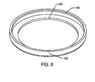
- base plate 160 of FIG. 6 permanently attaches to the housing.
- the housing has inner cut ledges at 168 when assembled the opposite ledges of the housing base plate 158 come together for this permanent fit. This tight connection is possible because of the small elastic properties of the plastic.
- This outermost portion of the device has some tamperproof elements.
- the lower portion of the housing base plate 162 of FIG. 6 will become defective if someone tries to pry or forcefully pull out the dog plate FIG. 5A
- This defect will be noticeable by the owner because of damages caused to the outer portion of the device by prying or applying excessive forces to the lower housing. This will raise awareness for the owner and should result in further protection against unauthorized users.
- This bottle locking device is a deterrent against potential prescription drug abusers. This device has been created in order to keep prescription drugs in the hands of their owners.
- This bottle locking device has been designed as a prevention device allowing prescription holders not only to have a more secure medical container, but also to be raise awareness when someone is tampering with their prescriptions. This is not a high security device; someone could still break or steal the bottle. This device is aimed at deterrence, removing the opportunity for teens to steal medications without, the prescription holder's knowledge.
- FIG-8 is a perspective view of a second embodiment of an assembled cap locking device that include a housing cover 100.
- the device may have one or more numerical cogs 92 and the housing may have a corresponding number of one or more gaps 102 through which the cogs protrude as shown in Figure 8 .
- the device may have 4 cogs 92 and four gaps in the housing as shown in Figure 8 , but the device is not limited to any particular number of cogs/gaps.
- the device also may have an outer housing 106 that surrounds the internal elements of the device and a lower housing 104 that closes the bottom of the device opposite of the cogs.
- the device may also have a reset pin 93 that allows the user to reset the numerical combination to which the cogs must be turned (1234, for example in this implementation) by the user to open the device.
- the reset pin 92 does not need to be a specific shape as any element/pin inserted into the reset hole would work (as long as the system is unlocked).
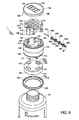
- FIG-9 is an exploded view of the second embodiment of the cap locking device.
- the device may have the one or more cogs 92 (cogs 92a, 92b, 92c and 92d in one implementation) and one or more cams 94 (cams 94a, 94b, 94c, and 94d in one implementation) that fit inside of one or more cogs.
- the cams and numeric cogs then slide onto a wheeled axel 86 and the assembled parts are placed into a set of slots 194 in the housing (the slots are shown in more detail in Figure 14A ) that support the cogs, cams and the wheeled axel in the housing.
- a spring 84 holds the cams firmly against the numeric cogs.
- a lock plate 190 is placed on top.
- the lock plate has an extension 124 as shown in more detail in Figure 10A that a slot 192 on each side of the housing (shown in Figures 9 and 10A )
- the positioning of slot 192 and extension 124 form a pivot point for the lock plate 190 and the housing 106.
- the lock plate 190 pivots depending on the positioning of the one or more cams 94, shown unlocked in Figure 9 since the lock plate 190 would be positioned down when it is unlocked.
- the cam 94d shows how the locking system works.
- the system is unlocked.
- the lock plate 190 is held upward and the device is locked.
- the housing cover 100 is attached to the housing 106.
- the housing cover holds the components of the numeric cogs and the lock plate in place in the device.
- the numeric cogs 92 stick above the housing cover when the device is assembled (as shown in Figure 8 ) so that a user can spin the cogs on their axel.
- the device has, below the housing cover when the device is assembled, a dog cap 184.
- the dog cap slips into the housing from the bottom and spins freely (when locked) within the housing.
- a lower housing 158 is attached to the lower part of the housing 164.
- the dog cap is slightly smaller than the housing that contains it which allows it to spin freely (when locked) within the housing.
- a lock arm 126 of the lock plate 190 engages the gaps 152 in the teeth 148 of the dog cap 184 (shown in Figure 9 and in more detail in Figure 11A ) allowing the user to put tension on the cap and remove the cap from the bottle to which the cap is attached.
- the user twists an unlocked cap onto a bottle, twists tight, and then mixes up the numbers which lifts the lock plate and allows the dog cap to spin freely thus locking the cap and access to the contents of the bottle. This allows for a greater safety and security measure for the contents within any bottle or container 90 since unlocking the cap requires the numerical code as well as being able to push down the cap and remove it from the bottle.
- FIG-10A is an isometric view of a lock plate 190 of the second embodiment of the cap locking device and FIG-10B is a side view of the lock plate that was not shown in FIG-10A .
- the lock plate 190 is the moving component of the locking device that engages and disengages from the dog cap 184 in order to lock and unlock the device.
- the lock plate 190 can have many different shapes and designs and an illustrative embodiment of the lock plate is shown in Figure 10A .
- the embodiment of the lock plate 190 shown in Figure 10A utilizes a lever-style system that pivots from the far end at the extension 124.
- the cams 94 shown in FIG-9 are the components that move the lock plate 190 up or down.
- the cams 94 fit within the numeric cogs 92 and together they act as one turning unit.
- the numeric cogs fit through one or more gaps 120 of the lock plate. There can be any number of gaps in the lock plate depending on the desired amount of numbers in the combination.
- the lock plate 190 is positioned above the cams 94.
- the lock plate also could be positioned below the cams and the cams in the locked position would push down on a lock plate.
- the cams push the lock plate up from the lower portion of the lock.
- the lock plate may have a resilient device 110, such as a spring, that fits into a hole 110 in the locking plate in order provide the necessary downward pressures needed to unlock the device.
- the cap locking device also allows downward pressures to be applied without the locking components being mechanically influenced to any substantial degree. This position has the advantage of eliminating the possibility of someone being able to push downward in order to "feel" the combination. Therefore the position of the locking plate acts as a tamper resisting element.
- Figure 10B shows how the cap locking device can and/or cannot be reset.
- the locking plate 190 has a reset access indent/outlet 114. This outlet 114 is only available when the system is unlocked (lock plate down). When the system is locked and the locking plate 190 is up, the reset access is blocked by arm 118 and the reset pin 93 cannot be inserted into the reset access outlet.
- the device To reset the cap locking device, the device must be unlocked (lock plate down in one embodiment) and the user puts the reset pin 93 through the reset outlet 106 of the housing. The reset pin then passes through the reset indent/outlet 114, and comes in contact with the cam 94a. All the cams 94a, 94b, 94c, 94d are able to move slightly along the axel. The cams 94a, 94b, 94c, 94d are held against their corresponding numeric cog by the spring 84 which sits at opposing end of the axel 86. The reset pin pushes the cams which move together compressing the spring 84 at the far end.
- the slight offset of the cams from the numeric cogs forced by the reset pin and allowed by the compression of the spring 84 permits the numeric cogs to spin independent from the cams
- the user can reset the system to a new combination. With the new combination aligned across the center of the cap the user releases the reset pin which causes the cams to slide back into place with the numeric cogs.
- the spring 84 causes the numeric cogs and cams to pair making them spin dependently with each other, thus allowing users to personalize the numbers.
- a user can only reset to a personal combination when the system is unlocked.
- the locking plate can be in two positions, up (locked) or down (unlocked).
- the locking plate 190 pivots from extension 124 and is pushed up or let down by the cams that push in four places directly at a position 116 when the cams are in the position without the flat surfaces being up. This pivot motion lifts or lowers a lock arm 112 and a lower portion of the lock arm 126 either engages or disengages the teeth of the dog cap in Fig-11A as described above.
- the cap locking device is based on an idea of a gear slipping device.
- the locking plate 190 in FIG. 9 and FIG. 10A that sits on the cams 94a-c is rotated into the flat position.
- the lock plate With this cam position 99 in FIG. 9 , the lock plate is in the down position making the connection between the lock plate of FIG. 10B at 126 and the dog plate FIG. 11A at 150 for applying the cap and 152 for removing the cap.
- FIG-11A is an isometric view of a dog cap 184 of the cap locking device.
- This is a cap that can be made to any size to fit a variety of bottles and the disclosure is not limited to the cap shown in Figure 11A .
- the dog cap 184 can spin freely within the cap locking device when it is locked.
- the lock arm 112 of the locking plate 190 shown in FIG-10B hits one of the four gaps 152 in the teeth 148 of the dog cap.
- the lock arm 112 and in particular the bottom of the lock arm 126 can push against a surface 150 the teeth 148 and apply torque to the teeth 148 allowing the cap to be rotated and therefore removed.
- each of the teeth there is an inlayed bevel 184, such as a forty five degree cut, that allows the numeric cogs to have slightly more space.
- the dog cap 184 is able to spin freely within the housing.
- the gap 146 from the teeth to edge of the cap makes the cap sit in the correct position in the housing wherein a counter-ridge 176 in the housing is shown in FIG 14B .
- the side 156 of the dog cap 184 may be smooth to slip within the housing to keep friction to a minimum so a user cannot remove the cap when it is locked as the dog cap 184 will slip inside the housing unless the cap locking device is unlocked.
- FIG-11B shows an example of a set of threads 157 within the dog cap 184 so that the assembled cap locking device can be screwed onto a bottle.
- FIG-12A shows a housing base plate 104 of the cap locking device. This piece holds the dog cap 184 within the housing.
- the housing base plate 104 may have a ridge 160 that is inward from an outer side 162 of the housing base plate 104.
- the ridge 160 extends inward in order to hold the dog cap 184 within the housing.
- FIG-12B show how the housing base plate 104 is permanently attached to the housing.
- the snap ridge 158 uses the small elasticity of plastic so that it can bend outward slightly when being applied. However, once it snaps into its counter part 178 shown in FIG-14B, the snap ridge cannot be removed.
- the housing base plate 104 can also be permanently attached with a glue or plastic weld.
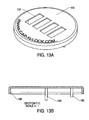
- FIG-13A illustrates the housing cover 100 of the cap locking device.
- the housing cover 100 holds the interior components in place.
- the slots 102 for the numbers are designed to be as large as possible. The actual number of slots depends on the number of numerical cogs used in the particular implementation and the cap locking device can use one or more numerical cogs.
- a top surface 100 can have anything; this one has the example of WWW.CAP-N-LOCK.COM engraved into it. The engravings can be depressed or raised in order to get a variety of messages across to the user.
- the top surface also has the slots 102 and the slots may be positioned in the center of the housing cover so that the numeric cogs are also substantially positioned in the center of the housing cover.
- FIG-13B is a side view of the housing cover 100.
- a permanent snap feature 198 is visible.
- the snap feature 198 of the housing cover fits the corresponding slots 188 as shown in FIG-14B.
- the extension 180 that holds the numeric cog and cam axel is shown, and the extension 182 that holds the lock plate is shown. Similar to the housing base plate the housing cover can permanently snap into place using ridges but, this piece can also be attached with glue or a plastic weld.
- FIG-14A is an upper isometric view of a housing of the cap locking device.
- the housing holds all the inner components together.
- the numeric cogs and cam axel slides into place from the top, resting in the pair of cut out groves 194. This grove holds the axel in place.
- the locking plate 190 shown in FIG-10A has extensions 124 that fit into the slots 192. This connection is the pivot point for the locking plate as described above.
- the lock arm 112 of FIG-10B fits into the lock arm brace 172. When assembled, there is a gap between the outer edge of the lock arm brace and the end 186 of the lock arm which allows for the pivoting movement of the locking plate without this component binding within the lock arm brace 172.
- the housing 106 may also have a cut out depression 196 so that there is room for the back of the locking plate 190 to pivot without binding.
- a side 166 of the housing is smooth in one implementation but it could have a lined or soft grip.
- There is one entry point 166 on the exterior of the housing which is a reset hole 106 of FIG 14A and FIG-14B .
- the reset hole is the access point to reset the combination of the cap.
- the locking cap device can only be reset when the system is unlocked. In order to reset the cap when it is unlocked, a user inserts a resetting pin 93 or any straight small rod such as a straightened paper clip through the housing reset hole 106.
- the reset pin then passes through the lock plate reset outlet 114 of FIG-10B of the locking plate and comes into contact with the cam 94a.
- the cams 94a, 94b, 94c, 94d compress a tension actuator 84 which causes the cams 94a, 94b, 94c, and 94d to slide off their connection with their congruent numeric cogs 92a, 92b, 92c, and 92d.
- the numeric cogs are held in place by the slots 120 in the lock plate of FIG-10A and the slots 102 in the housing cover of FIG 12B .
- the numeric cogs are held in place when the cams 94a-d are offset, then the numeric cogs can spin independently from the cams allowing the combination to be reset. When the pin is released, the cams slide back into their congruent numeric cog which allows a user to reset the system to a new personal combination. The device can only be reset when it is unlocked. When locked, the reset access outlet is blocked by 118 of FIG-10B, and a user cannot offset the cams 94a, 94b, 94c, and 94d from their corresponding numeric cog 92a, 92b, 92c, 92d.
- Each numeric cog/cam pair is held together by a spring 84 at the opposing end of the axel, this spring makes each pair spin as one.
- the four pairs of numeric cogs and cams spin as a paired unit revolving together in a linked position independent of the other pairs.
- This paired position is held together by opposing gears that connect the inter portions of the cams and cogs, which act as a single unit held together by a spring 84.
- Within each cam/cog pair there is one flat section on the cam. This flat section corresponds to the correct number in the combination. To unlock the combination all the flat sections on the cams need to be aligned so the flat sections on the cams line up horizontally with the lock plate. If even one pair of numeric cog/cams is even 36 rotational degrees offset (one number off) then the system remains locked and the lock plate is still held up.
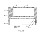
- FIG-14B is a side view of the housing.
- the side view shows how the dog cap of FIG-11B is contained in the housing.
- the ledge 176 holds the dog cap in its position.
- the side wall 174 is slightly larger in diameter than the dog cap that fits inside of it; this allows the cap to spin within the housing.
- the dog cap is made with a more slick plastic to reduce friction with the housing.
- the cap locking device described above and illustrated in the figures is a prevention device that may, for a prescription bottle, allow prescription holders not only to have a more secure medical container, but also to be raise awareness when someone is tampering with their prescriptions.
- the cap locking device is not a high security device because someone could still break or steal the bottle.
- the cap locking device is aimed at deterrence, removing the opportunity for teens to steal medications without the prescription holder's knowledge.
- the cap locking device In addition to being used to lock a medical prescription bottle, there are many other uses for the cap locking device such as a cap and lock for expensive perfumes, vitamins, supplements, and hazardous materials or any bottle in which it is desirable to lock the bottle closed.
- the overall diameter of the cap locking device can be adjusted as needed to fit each type of bottle.
- the two spacers described above can be made as a unitary spacer.
- the numbered wheels and the cogs could be inserted from below.
- the housing and the spacers might possibly be combined into one piece. If it was one piece the dial locking mechanism would have to be inserted from below.
- the housing could possibly be two pieces. If the half the housing was combined with a spacer on each, one may be able to create a design that came together like a sandwich.
- the locking plate could be designed differently, such as having two or more points of contact with the dog plate.
- the locking plate should be able to block the ability of the unit to be reset.
- half channel 138 on the spacers could be shaped differently and still retain its purpose for holding the spacers (and the dial lock within), not allowing the spacer to spin.
- the lock plate could have more than one portion that connects with the dog plate.
Landscapes
- Engineering & Computer Science (AREA)
- Mechanical Engineering (AREA)
- Closures For Containers (AREA)
Claims (15)
- Kappenschloss, das an einer Flasche befestigbar ist und umfasst:ein Gehäuse (100), das einen Kappenabschnitt und einen Basisabschnitt besitzt, wobei der Kappenabschnitt eine obere Oberfläche mit mehreren darin ausgebildeten Spalten (102) besitzt, wobei das Gehäuse enthält:ein drehbares Zahlenschloss (92, 94a-94c), das in dem Gehäuse angebracht ist, wobei das drehbare Zahlenschloss mit Ziffern versehene Zahnkränze (92) und Standardnocken (94a-94c) in mechanischer Beziehung zueinander besitzt, um den Zahnkränzen zu erlauben, sich unabhängig zu drehen, wobei die Zahnkränze in mehrere Einstellungen einstellbar sind;eine Mitnehmerplatte (156), die an der Flasche befestigbar ist und in dem Gehäuse frei drehbar montiert ist, wobei die Mitnehmerplatte einen Satz von Zähnen (148) besitzt, wobei der Satz von Zähnen wenigstens einem Kontaktpunkt für eine Verriegelungsplatte (122) erlaubt, eine ausreichende Spannung auszuüben, um die Kappe abzunehmen;wobei die Verriegelungsplatte (122) mehrere zweite Spalte (120) besitzt und in dem Gehäuse schwenkbar montiert ist und zwischen einer verriegelten Position und einer entriegelten Position beweglich ist, derart, dass die mehreren zweiten Spalte auf die mehreren ersten Spalte ausgerichtet werden, wodurch die mit Ziffern versehene Zahnkränze durch die mehreren ersten Spalten und die mehreren zweiten Spalten an ihrem Ort gehalten werden; undwobei die Verriegelungsplatte in der entriegelten Position angeordnet wird, wenn die Zahnkränze in eine vorgegebene Einstellung der mehreren Einstellun-gen eingestellt sind, und wobei die Verriegelungsplatte in der verriegelten Position angeordnet wird, wenn die Zahnkränze in eine Einstellung der mehreren Einstellungen, die von der vorgegebenen Einstellung verschieden ist, eingestellt sind.
- Kappenschloss nach Anspruch 1, das eine Freigabekomponente umfasst, die ein Zurücksetzen der Kennung der vorgegebenen Einstellung ermöglicht, wenn die Verriegelungsplatte in der entriegelten Position ist, wobei die Verriegelungsplatte das Zurücksetzen blockiert, wenn die Verriegelungsplatte in der verriegelten Position ist.
- Kappenschloss nach Anspruch 1, das ferner eine Ausrichtabstandshaltervorrichtung (140) umfasst, die an dem Gehäuse durch Einrasten montiert ist.
- Kappenschloss nach Anspruch 3, wobei das Gehäuse wenigstens einen Kanal (138) zum Führen der Zahnkränze (92) in eine Ausrichtung auf die mehreren ersten Spalte (120) besitzt und wobei der Kanal eine drehfeste dauerhafte Anbringung der Ausrichtabstandshaltervorrichtung (140) in dem Gehäuse schafft.
- Kappenschloss nach Anspruch 1, wobei die Verriegelungsplatte (122) eine Verlängerung (126) besitzt, die in Eingriff oder außer Eingriff mit der Mitnehmerplatte (156) angeordnet sein kann, und die Verriegelungsplatte in einer verriegelten Position oder einer entriegelten Position angeordnet wird, wobei die entriegelte Position eine Position ist, in der die Nocken (94a-94c) flach liegen, wodurch die Verlängerung der Verriegelungsplatte in Eingriff mit der Mitnehmerplatte gebracht wird, wodurch die Kappe von der Flasche abgenommen werden kann, und wobei die verriegelte Position eine Position ist, in der wenigstens einer der Nocken die Verlängerung außer Eingriff mit der Mitnehmerplatte bringt, wodurch die Kappe nicht von der Flasche abgenommen werden kann.
- Kappenschloss nach Anspruch 2, wobei der Satz Zahnräder (148) der Mitnehmerplatte (156) drehbar ist und die Freigabekomponente einen Abschnitt aufweist, der mit dem Satz von Zahnrädern verbunden ist, und der Abschnitt mit mehreren verschiedenen Punkten des Satzes von Zahnrädern verbunden sein kann, und wobei die Position, in der der Abschnitt mit dem Satz von Zahnrädern verbunden ist, von der Position des Zahlenschlosses in Bezug auf die Mitnehmerplatte abhängt.
- Kappenschloss nach Anspruch 6, wobei der Satz von Zahnrädern (148) gleitet, wenn die Verriegelungsplatte (122) in der verriegelten Position ist, und der Satz von Zahnrädern nicht gleiten kann, wenn die Verriegelungsplatte in der entriegelten Position ist.
- Kappenschloss nach Anspruch 1, wobei sich die Verriegelungsplatte (122) entweder über den Nocken unter den Nocken befindet.
- Verfahren zum Herstellen eines Kappenschlosses, das an einer Flasche befestigbar ist, das umfasst:Vorsehen eines Gehäuses (100), das einen Kappenabschnitt und einen Basisabschnitt besitzt, wobei der Kappenabschnitt eine obere Oberfläche besitzt, in der mehrere erste Spalte (102) vorhanden sind;Vorsehen eines drehbaren Zahlenschlosses (92, 94a-94c), das mit Zifforn versehene Zahnkränze (92) und Standardnocken (94a-94c) in gegenseitiger mechanischer Beziehung besitzt, um den Zahnkränzen zu erlauben, sich unabhängig zu drehen, wobei die Zahnkränze in mehrere Einstellungen einsteilbar sind;Anbringen des drehbaren Zahlenschlosses in einer Ausrichtabstandshaltervorrichtung (140);Vorsehen einer Mitnehmerplatte (156), die an der Flasche befestigbar ist und einen Satz von Zähnen (148) besitzt, wobei der Satz von Zähnen wenigstens einem Kontaktpunkt für eine Verriegelungsplatte (122) erlaubt, eine ausreichende Spannung auszuüben, um die Kappe zu abzunehmen;Anbringen der Mitnehmerplatte an dem Gehäuse derart, dass sie frei drehbar ist;Vorsehen einer Verriegelungsplatte (122), die mehrere zweite Spalte (120) besitzt und zwischen einer verriegelten Position und einer entriegelten Position beweglich ist;schwenkbares Anbringen der Verriegelungsplatte an dem Gehäuse über dem drehbaren Zahlenschloss, derart, dass(a) die mehreren zweiten Spalte auf die mehreren ersten Spalte ausgerichtet sind, wodurch die mit Ziffern versehenen Zahnkränze durch die mehreren ersten Spalte und die mehreren zweiten Spalte an ihrem Ort gehalten werden, und(b) die Verriegelungsplatte in der entriegelten Position angeordnet werden kann, wenn die Zahnkränze in eine vorgegebene Einstellung der mehreren Einstellungen eingestellt sind, und(c) die Verriegelungsplatte in der verriegelten Position angeordnet werden kann, wenn die Zahnkränze in eine Einstellung der mehreren Einstellungen, die von der vorgegebenen Einstellung verschieden ist, eingestellt sind.
- Verfahren nach Anspruch 9, das ferner das Anbringen der Ausrichtabstandshaltervorrichtung (140) an dem Gehäuse durch Einrasten umfasst.
- Verfahren nach Anspruch 9, das ferner das Führen der Zahnkränze (92) unter Verwendung eines Kanals (138) in der Ausrichtabstandshaltervorrichtung in eine Ausrichtung auf die mehreren ersten Spalte (102) umfasst, wobei der Kanal eine drehfeste dauerhafte Anbringung der Ausrichtabstandshaltervorrichtung (140) in dem Gehäuse schafft.
- Verfahren nach Anspruch 9, das ferner das Anordnen der Verriegelungsplatte (122) in Eingriff oder außer Eingriff mit der Mitnehmerplatte (156) umfasst, wobei die Verriegelungsplatte entriegelt ist, wenn die Nocken (94a-94c) eine Verlängerung der Verriegelungsplatte in Eingriff mit der Mitnehmerplatte anordnen, wodurch die Kappe von der Flasche abgenommen werden kann, und wobei die Verriegelungsplatte verriegelt ist, wenn wenigstens einer der Nocken die Verlängerung außer Eingriff mit der Mitnehmerplatte anordnet, wodurch die Kappe nicht von der Flasche abgenommen werden kann.
- Verfahren nach Anspruch 9, das ferner das Zurücksetzen unter Verwendung eines Rücksetzzugangs in der Verriegelungsplatte (122) umfasst, so dass die Kennung der vorgegebenen Einstellung zurückgesetzt werden kann, wenn die Verriegelungsplatte in Eingriff mit der Mitnehmerplatte (156) ist, wobei der Rücksetzzugang blockiert ist, wenn die Verriegelungsplatte außer Eingriff mit der Mitnehmerplatte angeordnet ist.
- Verfahren nach Anspruch 9, wobei der Satz von Zahnrädern (148) der Mitnehmerplatte (156) drehbar ist und die Freigabekomponente einen Abschnitt aufweist, der mit dem Satz von Zahnrädern verbunden ist, und der Abschnitt mit mehreren verschiedenen Punkten des Satzes von Zahnrädern verbunden sein kann und die Position, in der der Abschnitt mit den Satz von Zahnrädern verbunden ist, von der Position des Zahlenschlosses in Bezug auf die Mitnehmerplatte abhängt.
- Verfahren nach Anspruch 14, wobei der Satz von Zahnrädern (148) gleitet, wenn die Verriegelungsplatte (122) in der verriegelten Position ist, und wobei der Satz von Zahnrädern nicht gleiten kann, wenn die Verriegelungsplatte in der entriegelten Position ist.
Applications Claiming Priority (4)
| Application Number | Priority Date | Filing Date | Title |
|---|---|---|---|
| US23959709P | 2009-09-03 | 2009-09-03 | |
| US12/573,799 US8662330B2 (en) | 2009-09-03 | 2009-10-05 | Lockable cap for medical prescription bottle |
| US12/730,812 US8931652B2 (en) | 2009-09-03 | 2010-03-24 | Lockable cap for a bottle |
| PCT/US2010/047589 WO2011028845A1 (en) | 2009-09-03 | 2010-09-01 | Lockable cap for a bottle |
Publications (3)
| Publication Number | Publication Date |
|---|---|
| EP2473419A1 EP2473419A1 (de) | 2012-07-11 |
| EP2473419A4 EP2473419A4 (de) | 2013-01-23 |
| EP2473419B1 true EP2473419B1 (de) | 2014-03-12 |
Family
ID=43623297
Family Applications (1)
| Application Number | Title | Priority Date | Filing Date |
|---|---|---|---|
| EP20100814459 Active EP2473419B1 (de) | 2009-09-03 | 2010-09-01 | Verschliessbare kappe für eine flasche |
Country Status (5)
| Country | Link |
|---|---|
| US (4) | US8931652B2 (de) |
| EP (1) | EP2473419B1 (de) |
| CN (1) | CN102712399B (de) |
| CA (1) | CA3038994A1 (de) |
| WO (2) | WO2011028845A1 (de) |
Families Citing this family (42)
| Publication number | Priority date | Publication date | Assignee | Title |
|---|---|---|---|---|
| US8662330B2 (en) | 2009-09-03 | 2014-03-04 | Cap-N-Lock, Llc | Lockable cap for medical prescription bottle |
| US8931652B2 (en) | 2009-09-03 | 2015-01-13 | Cap N Lock Llc | Lockable cap for a bottle |
| CN102249035B (zh) * | 2011-04-21 | 2013-04-10 | 东莞市怡丰锁业有限公司 | 一种瓶盖的上锁解锁方法 |
| US8938999B2 (en) | 2011-11-14 | 2015-01-27 | Protectrx Llc | Locking cap apparatus and related methods |
| CN104684816B (zh) * | 2012-05-17 | 2017-06-30 | 纳尔逊·哈利勒&凯登公司 | 具有滑动锁的便携式安全餐盘 |
| CA2929801C (en) | 2013-11-05 | 2023-03-21 | Kenneth Anthony Loritz | Secured storage apparatus |
| US9758989B1 (en) * | 2014-03-26 | 2017-09-12 | Gatekeeper Innovation, Inc. | Locking cap with push button reset |
| US9424722B2 (en) | 2014-05-14 | 2016-08-23 | Unlimited Liability, LLC | Smart memory material lock devices |
| US20150353246A1 (en) * | 2014-06-04 | 2015-12-10 | Tom Coupland | Lockable Closure Device |
| US10099830B2 (en) * | 2014-08-19 | 2018-10-16 | Shaina Martinez | Lock it! |
| US10198975B2 (en) | 2014-11-05 | 2019-02-05 | Arthur Nazginov | Adjustable indicators for container assemblies |
| US10010486B2 (en) * | 2014-11-05 | 2018-07-03 | Arthur Nazginov | Adjustable indicators for container assemblies |
| US10201479B2 (en) | 2014-11-05 | 2019-02-12 | Arthur Nazginov | Adjustable indicators for container assemblies |
| US10180018B1 (en) | 2015-03-21 | 2019-01-15 | Gatekeeper Innovation, Inc. | Locking cap with processor |
| CN104948020A (zh) * | 2015-07-07 | 2015-09-30 | 包国菊 | 容器罐密码锁 |
| US11300746B2 (en) | 2017-06-28 | 2022-04-12 | Corning Research & Development Corporation | Fiber optic port module inserts, assemblies and methods of making the same |
| HRP20220022T1 (hr) | 2017-06-28 | 2022-04-01 | Corning Research & Development Corporation | Kompaktni konektori za optička vlakna |
| US10359577B2 (en) | 2017-06-28 | 2019-07-23 | Corning Research & Development Corporation | Multiports and optical connectors with rotationally discrete locking and keying features |
| US11668890B2 (en) * | 2017-06-28 | 2023-06-06 | Corning Research & Development Corporation | Multiports and other devices having optical connection ports with securing features and methods of making the same |
| CN107742375A (zh) * | 2017-09-29 | 2018-02-27 | 张鹏 | 组合式快递柜 |
| CN108364182A (zh) * | 2017-11-21 | 2018-08-03 | 阿里巴巴集团控股有限公司 | 一种商品防伪验证方法、装置及设备 |
| US10872482B1 (en) | 2017-11-22 | 2020-12-22 | Alexander Montgomery Colton | Personalized lid for prescription bottles |
| US11279535B1 (en) | 2018-03-06 | 2022-03-22 | Gatekeeper Innovation, Inc. | Clam shell cover cap and method of use |
| US10717571B1 (en) | 2018-03-06 | 2020-07-21 | Gatekeeper Innovation, Inc. | Clam shell cover cap and method of use |
| US11383903B1 (en) | 2018-07-24 | 2022-07-12 | Sherifa Gayle | Beverage cover alarm |
| EP3977190B1 (de) | 2019-05-31 | 2024-04-24 | Corning Research & Development Corporation | Multiports mit optischen verbindungsanschlüssen mit schiebebetätigern |
| US11294133B2 (en) | 2019-07-31 | 2022-04-05 | Corning Research & Development Corporation | Fiber optic networks using multiports and cable assemblies with cable-to-connector orientation |
| US10842713B1 (en) | 2019-08-15 | 2020-11-24 | Secure Medication Systems, Llc | Lockable container |
| CN110422470B (zh) * | 2019-08-27 | 2024-04-26 | 成都索真科技有限公司 | 瓶盖和容器 |
| WO2021076325A1 (en) | 2019-10-18 | 2021-04-22 | Corning Research & Development Corporation | Terminals having optical connection ports with securing features providing stable retention forces and methods of making the same |
| WO2022005952A1 (en) | 2020-06-29 | 2022-01-06 | Corning Research & Development Corporation | Terminals having a multi-fiber optical connection port that inhibits damage from single-fiber connectors |
| EP4189666A4 (de) * | 2020-07-29 | 2024-02-07 | Innocap Ltd. | Vorrichtung mit datumsanordnung |
| US11604320B2 (en) | 2020-09-30 | 2023-03-14 | Corning Research & Development Corporation | Connector assemblies for telecommunication enclosures |
| MX2023004967A (es) | 2020-10-30 | 2023-07-05 | Corning Res & Dev Corp | Conectores de fibra optica que tienen un collar de impermeabilizacion. |
| US11880076B2 (en) | 2020-11-30 | 2024-01-23 | Corning Research & Development Corporation | Fiber optic adapter assemblies including a conversion housing and a release housing |
| US11994722B2 (en) | 2020-11-30 | 2024-05-28 | Corning Research & Development Corporation | Fiber optic adapter assemblies including an adapter housing and a locking housing |
| US11927810B2 (en) | 2020-11-30 | 2024-03-12 | Corning Research & Development Corporation | Fiber optic adapter assemblies including a conversion housing and a release member |
| US11686913B2 (en) | 2020-11-30 | 2023-06-27 | Corning Research & Development Corporation | Fiber optic cable assemblies and connector assemblies having a crimp ring and crimp body and methods of fabricating the same |
| US11639259B1 (en) | 2021-06-08 | 2023-05-02 | Jason Snodgrass | Combination lock for liquid bottles |
| US11873146B1 (en) | 2022-07-21 | 2024-01-16 | Jose Gonzalez | Child safety device for medication dispenser |
| US12304719B1 (en) | 2022-07-21 | 2025-05-20 | Jose Gonzalez | Pivoting cap with locking mechanism for medication dispenser |
| KR102841745B1 (ko) * | 2022-12-27 | 2025-08-01 | 김형선 | 브러쉬 수납용 컨테이너 및 이를 이용한 브러쉬 수납방법 |
Family Cites Families (149)
| Publication number | Priority date | Publication date | Assignee | Title |
|---|---|---|---|---|
| US684656A (en) | 1901-06-18 | 1901-10-15 | Benjamin Watson | Mail-bag fastener. |
| US1071991A (en) | 1912-08-09 | 1913-09-02 | Harry Ebert | Bag-closure. |
| US1082906A (en) | 1913-01-30 | 1913-12-30 | John E Potts | Lock for automobiles and the like. |
| US1361605A (en) | 1919-05-09 | 1920-12-07 | Bemis Brothers Bag Company | Closure for bags |
| US1358352A (en) | 1919-11-26 | 1920-11-09 | Wheelock William Addison | Bottle top and lock |
| US1683294A (en) | 1927-01-22 | 1928-09-04 | Low Archie Edgar | Mail-bag lock |
| US1803217A (en) | 1929-08-19 | 1931-04-28 | Strayer Arthur Clare | Lock-seal bag |
| US1986057A (en) | 1932-07-19 | 1935-01-01 | Admiral D Hackworth | Waterproof case |
| US2009216A (en) | 1933-08-28 | 1935-07-23 | Benjamin H Anibal | Closure for bottles or the like |
| US2017698A (en) | 1935-04-03 | 1935-10-15 | Levy Joseph | Slide fastener |
| US2064432A (en) | 1936-04-25 | 1936-12-15 | Internat Seal And Knot Protect | Sealable container |
| GB495955A (en) | 1937-03-22 | 1938-11-22 | Lissfments P Mabille Ets | Improvements in combination locks for handbags and the like |
| US2136598A (en) | 1937-07-08 | 1938-11-15 | Arthur C Strayer | Lock seal bag |
| US2616470A (en) | 1948-07-23 | 1952-11-04 | Rifkin Jacob | Lockable bag |
| US3141221A (en) | 1962-11-13 | 1964-07-21 | Amtec Inc | Closure for flexible bags |
| US3200868A (en) | 1963-02-14 | 1965-08-17 | Eleanore B Strayer | Lock-seal night depository bag |
| US3151756A (en) | 1963-05-31 | 1964-10-06 | Gruen Paul John | Safety cap |
| US3266711A (en) | 1965-05-17 | 1966-08-16 | June E Song | Bag closure apparatus |
| US3394959A (en) | 1966-04-18 | 1968-07-30 | Hoffmann Marguerite | Lock for handbag clasp |
| US3421347A (en) | 1967-04-17 | 1969-01-14 | Gene E Sotory | Child-safe pill box |
| US3445021A (en) | 1967-06-27 | 1969-05-20 | John R Johnson | Combination locking closure for containers |
| US3426932A (en) * | 1967-07-17 | 1969-02-11 | William R Rouse | Tamper-proof poison bottle closure |
| US3481007A (en) | 1968-04-29 | 1969-12-02 | Nathan Scarritt Jr | Watertight closure for plastic bags |
| US3669296A (en) | 1970-11-12 | 1972-06-13 | Dennis H Drew | Safety container |
| US3702169A (en) | 1970-11-27 | 1972-11-07 | Gen Motors Corp | Friction welder with floating workpiece fixture |
| US3684117A (en) | 1971-03-18 | 1972-08-15 | Norbert Leopoldi | Dial-actuated safety cap |
| US3843007A (en) | 1973-07-05 | 1974-10-22 | K Meyer | Combination lock safety cap |
| US3850324A (en) | 1973-11-29 | 1974-11-26 | K Meyer | Threaded combination lock safety cap |
| US3901407A (en) | 1974-07-10 | 1975-08-26 | Mercury Manufacturing Company | Locking cap assembly for a filler neck |
| US3998078A (en) * | 1975-06-30 | 1976-12-21 | E. Edelmann & Co. | Limited torque locking fuel cap |
| US4302956A (en) | 1979-07-25 | 1981-12-01 | Mcmorrow John J | Blood identification means |
| JPS6013972Y2 (ja) | 1980-07-30 | 1985-05-04 | 株式会社斉工舎製作所 | 符号錠 |
| US4366687A (en) * | 1981-03-11 | 1983-01-04 | Long Manufacturing Co., Inc. | Changeable combination lock for desk drawers and the like |
| US4383425A (en) * | 1981-04-23 | 1983-05-17 | Presto Lock, Inc. | Safety device for combination locks |
| US4520641A (en) * | 1981-12-14 | 1985-06-04 | Presto Lock, Inc. | Combination lock with security feature |
| DE3447758A1 (de) * | 1983-12-28 | 1985-07-11 | Fuji Photo Film Co., Ltd., Minami-Ashigara, Kanagawa | Magnetband-kassette |
| US4615191A (en) | 1985-02-11 | 1986-10-07 | Master Lock Company | Barrel combination lock |
| KR890006969Y1 (ko) * | 1986-05-15 | 1989-10-13 | 김정욱 | 연료통의 뚜껑을 이용한 보조키 보관장치 |
| US4787222A (en) | 1986-11-24 | 1988-11-29 | Novatek Medical Inc. | Combination lock for blood identification system |
| US4794768A (en) | 1987-09-21 | 1989-01-03 | Moser Douglas J | Push button combination lock type gas cap and actuator employed therein |
| US4871264A (en) | 1988-01-05 | 1989-10-03 | Edward S. Robbins, Iii | Bag closure device and methods of fabricating the same |
| US4984698A (en) * | 1988-01-26 | 1991-01-15 | Stuckey William C | Lockable closure cap |
| US4907430A (en) | 1988-08-15 | 1990-03-13 | Pao Tao Lock Ltd. | Central control case lock |
| USD331364S (en) | 1990-09-13 | 1992-12-01 | Barker R Marshall | Bag sealer |
| US5050272A (en) | 1990-10-16 | 1991-09-24 | Anago, Inc. | Closure member for an ice bag |
| US5142888A (en) | 1991-06-27 | 1992-09-01 | Ling Chong Kuan | Rotatably unlockable combination lock having removable shackle |
| EP0528394B1 (de) | 1991-08-20 | 1995-11-22 | Gerhard Haubenwallner | Verpackungssystem |
| US5284262A (en) | 1992-11-19 | 1994-02-08 | O Nan Rocky K K | Programmable safety container and closure means |
| US5493279A (en) | 1993-03-24 | 1996-02-20 | Mas-Hamilton Group | Electronic combination lock with covert entry detection feature and method of covert entry detection |
| US5379489A (en) | 1993-04-13 | 1995-01-10 | Struckmeyer Corporation | Bag closure clamp with hinge-supplementing complementary cam surfaces |
| US5277325A (en) | 1993-07-06 | 1994-01-11 | Sunflower Enterprises Ltd. | Container with lockable cap |
| JP3001090U (ja) * | 1994-02-15 | 1994-08-16 | 修一 石田 | 回転式符合錠の秘密箱 |
| US5619775A (en) | 1994-07-29 | 1997-04-15 | Klinck; Barry W. | Safety latch for a removable clip for a colostomy bag |
| US5799792A (en) * | 1995-01-13 | 1998-09-01 | Abrums; Rolin L. | Nestable and stackable storage unit |
| USD372674S (en) | 1995-01-30 | 1996-08-13 | Weber Desna V | Bag clip with molded end |
| USD376691S (en) | 1995-03-08 | 1996-12-24 | John D. Brush & Co., Inc. | Portable security case |
| GB9517991D0 (en) | 1995-09-04 | 1995-11-08 | Aquaman Uk Ltd | Sealable bag |
| US5613282A (en) | 1995-09-22 | 1997-03-25 | Deddens, Sr.; John A. | Sealing apparatus |
| US5636539A (en) | 1995-09-27 | 1997-06-10 | Tsai; Cheng-Tao | Main body structure of combination lock |
| US5681115A (en) | 1996-01-02 | 1997-10-28 | Diederich; R. David | Child-resistant locking device for reclosable bag |
| US5735422A (en) | 1996-02-26 | 1998-04-07 | Binter; Randolph K. | Multiple part container |
| US5713108A (en) | 1996-06-27 | 1998-02-03 | Solomon; Howard | Flexible bag sealing device |
| US5983460A (en) | 1997-02-11 | 1999-11-16 | Hyde; Allen L. | Bag closure |
| US5875657A (en) | 1997-03-07 | 1999-03-02 | Qualtec Data Products, Inc. | Lock with removable cable adapter |
| FR2764582B1 (fr) | 1997-06-17 | 1999-09-03 | Flexico France Sarl | Sachet comprenant un dispositif de fermeture forme de profiles complementaires et dispositif de fermeture a cet effet |
| US6074094A (en) | 1997-06-25 | 2000-06-13 | Manolizi; Jorge Eleuterio | Safety locking for a bag |
| US5911764A (en) | 1997-07-28 | 1999-06-15 | Wei Kong; Yu | Bottle lock with a chuck device |
| US5913456A (en) | 1997-09-16 | 1999-06-22 | Dikeman; W. Cary | Pressurized portable drinking system |
| US5899099A (en) | 1998-06-04 | 1999-05-04 | Tsai; Cheng-Tao | Combination lock |
| US6290393B1 (en) | 2000-07-21 | 2001-09-18 | Reynolds Consumer Products, Inc. | Slider reclosable packages with dual peel seals |
| DE10039737A1 (de) | 2000-08-16 | 2002-02-28 | Franzen Soehne Gmbh & Co Kg S | Drehverschluss |
| DE10051666A1 (de) | 2000-10-18 | 2002-05-02 | Daimler Chrysler Ag | An einem Fahrzeug lösbar befestigter Behälter |
| US6386005B1 (en) | 2001-04-24 | 2002-05-14 | Lambert Kuo | Combination lock |
| US20020170639A1 (en) | 2001-05-16 | 2002-11-21 | Steinberg Adam Howard | Portable container |
| US20030188510A1 (en) | 2002-04-05 | 2003-10-09 | Vargas John T. | Snack food bag sealing apparatus and method of using same |
| US20040011098A1 (en) | 2002-07-17 | 2004-01-22 | Ping-Jan Yang | Compound locking device |
| US6786346B1 (en) | 2002-08-01 | 2004-09-07 | Ted Gurnard | Security closure for a container |
| AU2003270927A1 (en) | 2002-08-15 | 2004-03-03 | Carl Meyer | Locking mechanism |
| US6988642B2 (en) | 2002-10-29 | 2006-01-24 | Johnson & Johnson Consumer Companies | Tamper-evident dispenser bottle |
| EP1572548B1 (de) | 2002-11-13 | 2012-04-11 | Sehyang Industrial Co.,Ltd. | Verfahren und vorrichtung zum versiegeln einer packung |
| US6912878B2 (en) | 2003-02-24 | 2005-07-05 | Alpha Security Products, Inc. | Bottle security device |
| US20040234171A1 (en) | 2003-05-19 | 2004-11-25 | Dais Brian C. | Reclosable pouch with closure device that allows venting and/or an air-tight seal |
| WO2004103827A2 (en) | 2003-05-19 | 2004-12-02 | S. C. Johnson Home Storage, Inc. | Closure device for a reclosable pouch |
| US6793081B1 (en) | 2003-07-03 | 2004-09-21 | Jay S Derman | Locking neck ring |
| US7004340B2 (en) | 2003-07-25 | 2006-02-28 | Alpha Security Products, Inc. | Bottle security device |
| US20050050853A1 (en) | 2003-09-04 | 2005-03-10 | Barry Byron | Apparatus and method for sealing a bag |
| CN2646078Y (zh) * | 2004-01-30 | 2004-10-06 | 陈影 | 数码可调锁控安全容器盖 |
| US20050278186A1 (en) | 2004-06-15 | 2005-12-15 | Carlos De La Huerga | Word puzzle assembly and methods related thereto |
| EP1781135A4 (de) * | 2004-07-07 | 2013-01-23 | Mr Smith Inc | Tragekoffer für persönliche gegenstände |
| US7257972B2 (en) | 2004-08-20 | 2007-08-21 | Bright Aaron L | Locking case for a toothbrush |
| CA2488674A1 (en) | 2004-11-30 | 2006-05-30 | Montgomery Clifford Bondi | Multiple dimmer lighting system |
| US7600648B2 (en) | 2005-03-17 | 2009-10-13 | Douglas Taylor Hamer | Bottle cap with combination lock |
| US7107803B1 (en) | 2005-03-24 | 2006-09-19 | Swanson Neil J | Locking tube apparatus |
| US7549541B2 (en) | 2005-07-26 | 2009-06-23 | Rexam Closure Systems Inc. | Child-resistant compact for blister card products |
| US7412854B2 (en) | 2005-09-27 | 2008-08-19 | Richard Raemisch | Lightweight cable lock |
| WO2007070550A2 (en) | 2005-12-12 | 2007-06-21 | Master Lock Company Llc | Lock with actuation indicator |
| TWI292006B (en) | 2006-01-05 | 2008-01-01 | Sinox Co Ltd | Lock box |
| US7252204B1 (en) | 2006-01-17 | 2007-08-07 | Steven Douglas Small | Combination lock container |
| CN2897860Y (zh) | 2006-05-09 | 2007-05-09 | 才文君 | 密码防伪瓶盖 |
| US7337637B2 (en) | 2006-07-05 | 2008-03-04 | Fuben Kan | Combination resetting member for cable lock |
| US7540175B2 (en) | 2006-10-31 | 2009-06-02 | Master Lock Company Llc | Mountable safe |
| US8666539B2 (en) | 2007-03-13 | 2014-03-04 | Medicasafe, Inc. | Method, system and apparatus for controlling patient access to medicaments |
| US20080302794A1 (en) | 2007-06-08 | 2008-12-11 | Richard John Wagner | Security Closure for a Container |
| US9355218B2 (en) | 2007-10-30 | 2016-05-31 | Carefusion 303, Inc. | Secure medication transport and administration system |
| CN201143150Y (zh) * | 2007-12-28 | 2008-11-05 | 上海市杨浦区控江二村小学 | 安全热水瓶 |
| US7617935B2 (en) * | 2008-01-10 | 2009-11-17 | Anderson Packaging, Inc. | Reusable child-resistant, senior friendly unit dose container |
| US8071459B2 (en) | 2008-04-17 | 2011-12-06 | Freescale Semiconductor, Inc. | Method of sealing an air gap in a layer of a semiconductor structure and semiconductor structure |
| US7677065B1 (en) | 2008-11-18 | 2010-03-16 | Jin Tay Industries Co., Ltd. | Lock for a USB connector |
| WO2010078898A1 (en) | 2008-12-18 | 2010-07-15 | Bayer Consumer Care Ag | Closure for pouches |
| US8020415B2 (en) | 2009-06-04 | 2011-09-20 | Stampp W. Corbin | Locking pill bottle |
| US8662330B2 (en) | 2009-09-03 | 2014-03-04 | Cap-N-Lock, Llc | Lockable cap for medical prescription bottle |
| US8931652B2 (en) | 2009-09-03 | 2015-01-13 | Cap N Lock Llc | Lockable cap for a bottle |
| US20110079058A1 (en) | 2009-09-28 | 2011-04-07 | Nielsen Simon S | Locking Top for Container |
| TWM397365U (en) | 2010-02-26 | 2011-02-01 | qiu-song Wang | Container |
| US8413811B1 (en) * | 2010-12-20 | 2013-04-09 | Thomas Arendt | Dispenser package for medical/dental devices |
| US20120168461A1 (en) | 2011-01-05 | 2012-07-05 | Diversapack Llc | Reuseable housing for flexible pouch with fitment |
| US8517193B1 (en) | 2011-02-03 | 2013-08-27 | Steven Douglas Small | Combination locking bottle holder |
| WO2012112633A1 (en) | 2011-02-15 | 2012-08-23 | Master Lock Company Llc | Portable lockable enclosure |
| EP2508442A3 (de) * | 2011-04-04 | 2013-05-29 | Curver Luxembourg SARL | Lagerbehälter |
| US9367984B2 (en) | 2011-04-14 | 2016-06-14 | GCX Corporation | Enhanced modular drawer structures, systems, and methods |
| US8875915B2 (en) | 2011-09-12 | 2014-11-04 | Secure Medication Systems, Llc | Container having a programmable combination locking cap |
| US8297087B1 (en) | 2011-10-12 | 2012-10-30 | Ging Hwa Long Hardware Industry Co., Ltd. | Idiot-proof lock device that prevents a user from changing the code freely and unintentionally |
| US8938999B2 (en) | 2011-11-14 | 2015-01-27 | Protectrx Llc | Locking cap apparatus and related methods |
| US20140116536A1 (en) | 2012-10-26 | 2014-05-01 | Baker Commodities, Inc. | Locking enclosure for a valve, port, or other fixture |
| CN103043295B (zh) | 2012-12-07 | 2014-10-29 | 慈溪市美德工贸有限公司 | 数码袋自锁式高压密封装置 |
| US8939301B1 (en) | 2013-01-30 | 2015-01-27 | Steven Douglas Small | Combination locking storage container |
| US8944263B1 (en) | 2013-02-15 | 2015-02-03 | Steven Douglas Small | Prescription drug lock box |
| US9555942B2 (en) * | 2013-06-05 | 2017-01-31 | Brent Bradley Ackerman | Locking medicine container |
| CN105378195B (zh) | 2013-07-12 | 2018-04-17 | Invue安全产品公司 | 用于与电子钥匙一起使用的商品安全装置 |
| US9758989B1 (en) | 2014-03-26 | 2017-09-12 | Gatekeeper Innovation, Inc. | Locking cap with push button reset |
| US9890558B2 (en) | 2014-04-21 | 2018-02-13 | Secure Medication Systems, Llc | Encoding tool for a combination cap |
| US9345300B2 (en) | 2014-06-05 | 2016-05-24 | Sang Il Park | Bag with anti-theft function cross reference to related application |
| USD747607S1 (en) | 2014-07-29 | 2016-01-19 | Secure Medication Systems, Llc | Rectangular locking container |
| USD746058S1 (en) * | 2014-07-29 | 2015-12-29 | Secure Medication Systems, Llc | Locking container |
| USD741713S1 (en) | 2014-07-29 | 2015-10-27 | Secure Medication Systems, Llc | Locking cap |
| US10180018B1 (en) | 2015-03-21 | 2019-01-15 | Gatekeeper Innovation, Inc. | Locking cap with processor |
| USD761008S1 (en) * | 2015-03-27 | 2016-07-12 | Ralande Group Llc | Medical safety container |
| US10037640B2 (en) | 2015-08-03 | 2018-07-31 | Sneakguard, Llc | Secure storage device |
| US10145492B2 (en) | 2016-07-14 | 2018-12-04 | Surelock, Llc | Valve lockout device with viewing port and method |
| US20180051488A1 (en) | 2016-08-18 | 2018-02-22 | Gatekeeper Innovation Inc. | Bag lock device and method for using the same |
| US10460539B2 (en) | 2016-08-24 | 2019-10-29 | Universal City Studios Llc | Loose item management systems and methods for amusement park rides |
| US11238682B2 (en) | 2017-01-05 | 2022-02-01 | Satish Poddar | Locking medication containers and methods of use thereof |
| DE102017002014A1 (de) | 2017-03-03 | 2018-09-06 | Sudhaus Gmbh & Co. Kg | Schließvorrichtung für Behältnisse, Türen, Schränke, Möbel od. dgl. |
| US10335349B2 (en) | 2017-06-20 | 2019-07-02 | Addinex Technologies, Inc. | Prescription drug abuse prevention system |
| WO2019075036A1 (en) | 2017-10-10 | 2019-04-18 | Loures James | IMPROVED PACKAGE RECEPTACLE AND ANTI-THEFT DEVICE AND ANTI-THEFT SYSTEM |
| US11279535B1 (en) | 2018-03-06 | 2022-03-22 | Gatekeeper Innovation, Inc. | Clam shell cover cap and method of use |
| US10717571B1 (en) | 2018-03-06 | 2020-07-21 | Gatekeeper Innovation, Inc. | Clam shell cover cap and method of use |
| US11535435B2 (en) | 2020-05-15 | 2022-12-27 | Catherine Netter | Locking beverage container |
| US11262148B1 (en) | 2021-02-19 | 2022-03-01 | Sfus Inc. | Lock |
-
2010
- 2010-03-24 US US12/730,812 patent/US8931652B2/en active Active
- 2010-09-01 WO PCT/US2010/047589 patent/WO2011028845A1/en not_active Ceased
- 2010-09-01 CN CN201080049649.2A patent/CN102712399B/zh active Active
- 2010-09-01 EP EP20100814459 patent/EP2473419B1/de active Active
-
2012
- 2012-08-14 US US13/585,742 patent/US9199773B2/en active Active
-
2016
- 2016-10-28 US US15/338,133 patent/US12234070B2/en active Active
-
2017
- 2017-10-30 CA CA3038994A patent/CA3038994A1/en active Pending
- 2017-10-30 WO PCT/US2017/058959 patent/WO2018081676A1/en not_active Ceased
-
2025
- 2025-02-11 US US19/050,641 patent/US20250178807A1/en active Pending
Also Published As
| Publication number | Publication date |
|---|---|
| EP2473419A4 (de) | 2013-01-23 |
| CN102712399A (zh) | 2012-10-03 |
| US20130043204A1 (en) | 2013-02-21 |
| CA3038994A1 (en) | 2018-05-03 |
| US8931652B2 (en) | 2015-01-13 |
| WO2011028845A1 (en) | 2011-03-10 |
| US12234070B2 (en) | 2025-02-25 |
| US9199773B2 (en) | 2015-12-01 |
| WO2018081676A1 (en) | 2018-05-03 |
| EP2473419A1 (de) | 2012-07-11 |
| US20180079569A1 (en) | 2018-03-22 |
| US20110049080A1 (en) | 2011-03-03 |
| US20250178807A1 (en) | 2025-06-05 |
| CN102712399B (zh) | 2015-04-01 |
Similar Documents
| Publication | Publication Date | Title |
|---|---|---|
| EP2473419B1 (de) | Verschliessbare kappe für eine flasche | |
| US11273963B2 (en) | Lockable cap for medical prescription bottle | |
| US11008777B2 (en) | Locking cap with push button reset | |
| US8938999B2 (en) | Locking cap apparatus and related methods | |
| US8539799B2 (en) | Combination lock | |
| US8769999B2 (en) | Combination lock | |
| US8931313B2 (en) | Lock with dual locking system | |
| EP2336466B1 (de) | Vorhängeschlösser | |
| US7140209B2 (en) | Padlock with fully integrated dual locking systems | |
| CN100537986C (zh) | 号码锁 | |
| US4111014A (en) | Combination lock | |
| US20100154487A1 (en) | Double Cylinder Lock | |
| AU2008265749B2 (en) | Combination lock | |
| CN101583771A (zh) | 组合挂锁 | |
| CN2197442Y (zh) | 机械按钮式密码锁保险柜 | |
| JPH0230863A (ja) | ダイヤル錠 |
Legal Events
| Date | Code | Title | Description |
|---|---|---|---|
| PUAI | Public reference made under article 153(3) epc to a published international application that has entered the european phase |
Free format text: ORIGINAL CODE: 0009012 |
|
| 17P | Request for examination filed |
Effective date: 20120403 |
|
| AK | Designated contracting states |
Kind code of ref document: A1 Designated state(s): AL AT BE BG CH CY CZ DE DK EE ES FI FR GB GR HR HU IE IS IT LI LT LU LV MC MK MT NL NO PL PT RO SE SI SK SM TR |
|
| DAX | Request for extension of the european patent (deleted) | ||
| R17P | Request for examination filed (corrected) |
Effective date: 20120328 |
|
| RBV | Designated contracting states (corrected) |
Designated state(s): AL AT BE BG CH CY CZ DE DK EE ES FI FR GB GR HR HU IE IS IT LI LT LU LV MC MK MT NL NO PL PT RO SE SI SK SM TR |
|
| A4 | Supplementary search report drawn up and despatched |
Effective date: 20121220 |
|
| RIC1 | Information provided on ipc code assigned before grant |
Ipc: B65D 55/14 20060101AFI20121214BHEP |
|
| GRAP | Despatch of communication of intention to grant a patent |
Free format text: ORIGINAL CODE: EPIDOSNIGR1 |
|
| INTG | Intention to grant announced |
Effective date: 20130918 |
|
| GRAS | Grant fee paid |
Free format text: ORIGINAL CODE: EPIDOSNIGR3 |
|
| GRAA | (expected) grant |
Free format text: ORIGINAL CODE: 0009210 |
|
| AK | Designated contracting states |
Kind code of ref document: B1 Designated state(s): AL AT BE BG CH CY CZ DE DK EE ES FI FR GB GR HR HU IE IS IT LI LT LU LV MC MK MT NL NO PL PT RO SE SI SK SM TR |
|
| REG | Reference to a national code |
Ref country code: GB Ref legal event code: FG4D |
|
| REG | Reference to a national code |
Ref country code: CH Ref legal event code: EP |
|
| REG | Reference to a national code |
Ref country code: AT Ref legal event code: REF Ref document number: 656126 Country of ref document: AT Kind code of ref document: T Effective date: 20140315 |
|
| REG | Reference to a national code |
Ref country code: IE Ref legal event code: FG4D |
|
| REG | Reference to a national code |
Ref country code: DE Ref legal event code: R096 Ref document number: 602010014332 Country of ref document: DE Effective date: 20140424 |
|
| REG | Reference to a national code |
Ref country code: NL Ref legal event code: T3 |
|
| PG25 | Lapsed in a contracting state [announced via postgrant information from national office to epo] |
Ref country code: NO Free format text: LAPSE BECAUSE OF FAILURE TO SUBMIT A TRANSLATION OF THE DESCRIPTION OR TO PAY THE FEE WITHIN THE PRESCRIBED TIME-LIMIT Effective date: 20140612 Ref country code: LT Free format text: LAPSE BECAUSE OF FAILURE TO SUBMIT A TRANSLATION OF THE DESCRIPTION OR TO PAY THE FEE WITHIN THE PRESCRIBED TIME-LIMIT Effective date: 20140312 |
|
| REG | Reference to a national code |
Ref country code: AT Ref legal event code: MK05 Ref document number: 656126 Country of ref document: AT Kind code of ref document: T Effective date: 20140312 |
|
| REG | Reference to a national code |
Ref country code: LT Ref legal event code: MG4D |
|
| PG25 | Lapsed in a contracting state [announced via postgrant information from national office to epo] |
Ref country code: FI Free format text: LAPSE BECAUSE OF FAILURE TO SUBMIT A TRANSLATION OF THE DESCRIPTION OR TO PAY THE FEE WITHIN THE PRESCRIBED TIME-LIMIT Effective date: 20140312 Ref country code: CY Free format text: LAPSE BECAUSE OF FAILURE TO SUBMIT A TRANSLATION OF THE DESCRIPTION OR TO PAY THE FEE WITHIN THE PRESCRIBED TIME-LIMIT Effective date: 20140312 Ref country code: SE Free format text: LAPSE BECAUSE OF FAILURE TO SUBMIT A TRANSLATION OF THE DESCRIPTION OR TO PAY THE FEE WITHIN THE PRESCRIBED TIME-LIMIT Effective date: 20140312 |
|
| PG25 | Lapsed in a contracting state [announced via postgrant information from national office to epo] |
Ref country code: HR Free format text: LAPSE BECAUSE OF FAILURE TO SUBMIT A TRANSLATION OF THE DESCRIPTION OR TO PAY THE FEE WITHIN THE PRESCRIBED TIME-LIMIT Effective date: 20140312 Ref country code: LV Free format text: LAPSE BECAUSE OF FAILURE TO SUBMIT A TRANSLATION OF THE DESCRIPTION OR TO PAY THE FEE WITHIN THE PRESCRIBED TIME-LIMIT Effective date: 20140312 |
|
| PG25 | Lapsed in a contracting state [announced via postgrant information from national office to epo] |
Ref country code: EE Free format text: LAPSE BECAUSE OF FAILURE TO SUBMIT A TRANSLATION OF THE DESCRIPTION OR TO PAY THE FEE WITHIN THE PRESCRIBED TIME-LIMIT Effective date: 20140312 Ref country code: BG Free format text: LAPSE BECAUSE OF FAILURE TO SUBMIT A TRANSLATION OF THE DESCRIPTION OR TO PAY THE FEE WITHIN THE PRESCRIBED TIME-LIMIT Effective date: 20140612 Ref country code: CZ Free format text: LAPSE BECAUSE OF FAILURE TO SUBMIT A TRANSLATION OF THE DESCRIPTION OR TO PAY THE FEE WITHIN THE PRESCRIBED TIME-LIMIT Effective date: 20140312 Ref country code: RO Free format text: LAPSE BECAUSE OF FAILURE TO SUBMIT A TRANSLATION OF THE DESCRIPTION OR TO PAY THE FEE WITHIN THE PRESCRIBED TIME-LIMIT Effective date: 20140312 Ref country code: BE Free format text: LAPSE BECAUSE OF FAILURE TO SUBMIT A TRANSLATION OF THE DESCRIPTION OR TO PAY THE FEE WITHIN THE PRESCRIBED TIME-LIMIT Effective date: 20140312 Ref country code: IS Free format text: LAPSE BECAUSE OF FAILURE TO SUBMIT A TRANSLATION OF THE DESCRIPTION OR TO PAY THE FEE WITHIN THE PRESCRIBED TIME-LIMIT Effective date: 20140712 |
|
| PG25 | Lapsed in a contracting state [announced via postgrant information from national office to epo] |
Ref country code: SK Free format text: LAPSE BECAUSE OF FAILURE TO SUBMIT A TRANSLATION OF THE DESCRIPTION OR TO PAY THE FEE WITHIN THE PRESCRIBED TIME-LIMIT Effective date: 20140312 Ref country code: AT Free format text: LAPSE BECAUSE OF FAILURE TO SUBMIT A TRANSLATION OF THE DESCRIPTION OR TO PAY THE FEE WITHIN THE PRESCRIBED TIME-LIMIT Effective date: 20140312 Ref country code: ES Free format text: LAPSE BECAUSE OF FAILURE TO SUBMIT A TRANSLATION OF THE DESCRIPTION OR TO PAY THE FEE WITHIN THE PRESCRIBED TIME-LIMIT Effective date: 20140312 Ref country code: PL Free format text: LAPSE BECAUSE OF FAILURE TO SUBMIT A TRANSLATION OF THE DESCRIPTION OR TO PAY THE FEE WITHIN THE PRESCRIBED TIME-LIMIT Effective date: 20140312 |
|
| REG | Reference to a national code |
Ref country code: DE Ref legal event code: R097 Ref document number: 602010014332 Country of ref document: DE |
|
| PG25 | Lapsed in a contracting state [announced via postgrant information from national office to epo] |
Ref country code: PT Free format text: LAPSE BECAUSE OF FAILURE TO SUBMIT A TRANSLATION OF THE DESCRIPTION OR TO PAY THE FEE WITHIN THE PRESCRIBED TIME-LIMIT Effective date: 20140714 |
|
| PLBE | No opposition filed within time limit |
Free format text: ORIGINAL CODE: 0009261 |
|
| STAA | Information on the status of an ep patent application or granted ep patent |
Free format text: STATUS: NO OPPOSITION FILED WITHIN TIME LIMIT |
|
| PG25 | Lapsed in a contracting state [announced via postgrant information from national office to epo] |
Ref country code: DK Free format text: LAPSE BECAUSE OF FAILURE TO SUBMIT A TRANSLATION OF THE DESCRIPTION OR TO PAY THE FEE WITHIN THE PRESCRIBED TIME-LIMIT Effective date: 20140312 |
|
| 26N | No opposition filed |
Effective date: 20141215 |
|
| REG | Reference to a national code |
Ref country code: DE Ref legal event code: R097 Ref document number: 602010014332 Country of ref document: DE Effective date: 20141215 |
|
| PG25 | Lapsed in a contracting state [announced via postgrant information from national office to epo] |
Ref country code: IT Free format text: LAPSE BECAUSE OF FAILURE TO SUBMIT A TRANSLATION OF THE DESCRIPTION OR TO PAY THE FEE WITHIN THE PRESCRIBED TIME-LIMIT Effective date: 20140312 |
|
| PG25 | Lapsed in a contracting state [announced via postgrant information from national office to epo] |
Ref country code: MC Free format text: LAPSE BECAUSE OF FAILURE TO SUBMIT A TRANSLATION OF THE DESCRIPTION OR TO PAY THE FEE WITHIN THE PRESCRIBED TIME-LIMIT Effective date: 20140312 Ref country code: LU Free format text: LAPSE BECAUSE OF FAILURE TO SUBMIT A TRANSLATION OF THE DESCRIPTION OR TO PAY THE FEE WITHIN THE PRESCRIBED TIME-LIMIT Effective date: 20140901 |
|
| REG | Reference to a national code |
Ref country code: CH Ref legal event code: PL |
|
| REG | Reference to a national code |
Ref country code: IE Ref legal event code: MM4A |
|
| PG25 | Lapsed in a contracting state [announced via postgrant information from national office to epo] |
Ref country code: SI Free format text: LAPSE BECAUSE OF FAILURE TO SUBMIT A TRANSLATION OF THE DESCRIPTION OR TO PAY THE FEE WITHIN THE PRESCRIBED TIME-LIMIT Effective date: 20140312 Ref country code: LI Free format text: LAPSE BECAUSE OF NON-PAYMENT OF DUE FEES Effective date: 20140930 Ref country code: CH Free format text: LAPSE BECAUSE OF NON-PAYMENT OF DUE FEES Effective date: 20140930 |
|
| PG25 | Lapsed in a contracting state [announced via postgrant information from national office to epo] |
Ref country code: IE Free format text: LAPSE BECAUSE OF NON-PAYMENT OF DUE FEES Effective date: 20140901 |
|
| PG25 | Lapsed in a contracting state [announced via postgrant information from national office to epo] |
Ref country code: SM Free format text: LAPSE BECAUSE OF FAILURE TO SUBMIT A TRANSLATION OF THE DESCRIPTION OR TO PAY THE FEE WITHIN THE PRESCRIBED TIME-LIMIT Effective date: 20140312 |
|
| PG25 | Lapsed in a contracting state [announced via postgrant information from national office to epo] |
Ref country code: GR Free format text: LAPSE BECAUSE OF FAILURE TO SUBMIT A TRANSLATION OF THE DESCRIPTION OR TO PAY THE FEE WITHIN THE PRESCRIBED TIME-LIMIT Effective date: 20140613 Ref country code: MT Free format text: LAPSE BECAUSE OF FAILURE TO SUBMIT A TRANSLATION OF THE DESCRIPTION OR TO PAY THE FEE WITHIN THE PRESCRIBED TIME-LIMIT Effective date: 20140312 |
|
| PG25 | Lapsed in a contracting state [announced via postgrant information from national office to epo] |
Ref country code: HU Free format text: LAPSE BECAUSE OF FAILURE TO SUBMIT A TRANSLATION OF THE DESCRIPTION OR TO PAY THE FEE WITHIN THE PRESCRIBED TIME-LIMIT; INVALID AB INITIO Effective date: 20100901 Ref country code: TR Free format text: LAPSE BECAUSE OF FAILURE TO SUBMIT A TRANSLATION OF THE DESCRIPTION OR TO PAY THE FEE WITHIN THE PRESCRIBED TIME-LIMIT Effective date: 20140312 |
|
| REG | Reference to a national code |
Ref country code: FR Ref legal event code: PLFP Year of fee payment: 7 |
|
| REG | Reference to a national code |
Ref country code: FR Ref legal event code: PLFP Year of fee payment: 8 |
|
| PG25 | Lapsed in a contracting state [announced via postgrant information from national office to epo] |
Ref country code: MK Free format text: LAPSE BECAUSE OF FAILURE TO SUBMIT A TRANSLATION OF THE DESCRIPTION OR TO PAY THE FEE WITHIN THE PRESCRIBED TIME-LIMIT Effective date: 20140312 |
|
| REG | Reference to a national code |
Ref country code: FR Ref legal event code: PLFP Year of fee payment: 9 |
|
| PG25 | Lapsed in a contracting state [announced via postgrant information from national office to epo] |
Ref country code: AL Free format text: LAPSE BECAUSE OF FAILURE TO SUBMIT A TRANSLATION OF THE DESCRIPTION OR TO PAY THE FEE WITHIN THE PRESCRIBED TIME-LIMIT Effective date: 20140312 |
|
| REG | Reference to a national code |
Ref country code: DE Ref legal event code: R081 Ref document number: 602010014332 Country of ref document: DE Owner name: RXGUARDIAN INC., SACRAMENTO, US Free format text: FORMER OWNER: CAP-N-LOCK, LLC, LINCOLN, CALIF., US |
|
| REG | Reference to a national code |
Ref country code: GB Ref legal event code: 732E Free format text: REGISTERED BETWEEN 20230309 AND 20230315 |
|
| P01 | Opt-out of the competence of the unified patent court (upc) registered |
Effective date: 20230515 |
|
| PGFP | Annual fee paid to national office [announced via postgrant information from national office to epo] |
Ref country code: NL Payment date: 20250815 Year of fee payment: 16 |
|
| PGFP | Annual fee paid to national office [announced via postgrant information from national office to epo] |
Ref country code: DE Payment date: 20250819 Year of fee payment: 16 |
|
| PGFP | Annual fee paid to national office [announced via postgrant information from national office to epo] |
Ref country code: GB Payment date: 20250827 Year of fee payment: 16 |
|
| PGFP | Annual fee paid to national office [announced via postgrant information from national office to epo] |
Ref country code: FR Payment date: 20250820 Year of fee payment: 16 |