EP2473144B1 - Pneumatic pressure output control by drive valve duty cycle calibration - Google Patents
Pneumatic pressure output control by drive valve duty cycle calibration Download PDFInfo
- Publication number
- EP2473144B1 EP2473144B1 EP10745088.4A EP10745088A EP2473144B1 EP 2473144 B1 EP2473144 B1 EP 2473144B1 EP 10745088 A EP10745088 A EP 10745088A EP 2473144 B1 EP2473144 B1 EP 2473144B1
- Authority
- EP
- European Patent Office
- Prior art keywords
- pressure
- valve
- duty cycle
- open
- port
- Prior art date
- Legal status (The legal status is an assumption and is not a legal conclusion. Google has not performed a legal analysis and makes no representation as to the accuracy of the status listed.)
- Active
Links
- 238000000034 method Methods 0.000 claims description 17
- 230000008859 change Effects 0.000 claims description 15
- 239000007789 gas Substances 0.000 description 21
- 230000007704 transition Effects 0.000 description 8
- 238000001356 surgical procedure Methods 0.000 description 7
- 230000006870 function Effects 0.000 description 6
- 210000001525 retina Anatomy 0.000 description 5
- 239000000523 sample Substances 0.000 description 5
- 238000005520 cutting process Methods 0.000 description 4
- 238000001802 infusion Methods 0.000 description 4
- 206010038848 Retinal detachment Diseases 0.000 description 3
- 230000008878 coupling Effects 0.000 description 3
- 238000010168 coupling process Methods 0.000 description 3
- 238000005859 coupling reaction Methods 0.000 description 3
- 238000004519 manufacturing process Methods 0.000 description 3
- 230000004264 retinal detachment Effects 0.000 description 3
- IJGRMHOSHXDMSA-UHFFFAOYSA-N Atomic nitrogen Chemical compound N#N IJGRMHOSHXDMSA-UHFFFAOYSA-N 0.000 description 2
- 206010012689 Diabetic retinopathy Diseases 0.000 description 2
- 208000001351 Epiretinal Membrane Diseases 0.000 description 2
- 208000002367 Retinal Perforations Diseases 0.000 description 2
- 208000034698 Vitreous haemorrhage Diseases 0.000 description 2
- 206010064930 age-related macular degeneration Diseases 0.000 description 2
- 229910052782 aluminium Inorganic materials 0.000 description 2
- XAGFODPZIPBFFR-UHFFFAOYSA-N aluminium Chemical compound [Al] XAGFODPZIPBFFR-UHFFFAOYSA-N 0.000 description 2
- 230000000740 bleeding effect Effects 0.000 description 2
- 210000004369 blood Anatomy 0.000 description 2
- 239000008280 blood Substances 0.000 description 2
- 238000010586 diagram Methods 0.000 description 2
- 230000003993 interaction Effects 0.000 description 2
- 208000002780 macular degeneration Diseases 0.000 description 2
- 208000029233 macular holes Diseases 0.000 description 2
- 230000008569 process Effects 0.000 description 2
- 230000002207 retinal effect Effects 0.000 description 2
- 231100000241 scar Toxicity 0.000 description 2
- 208000002177 Cataract Diseases 0.000 description 1
- 206010007766 Cataract traumatic Diseases 0.000 description 1
- 206010016654 Fibrosis Diseases 0.000 description 1
- 208000032843 Hemorrhage Diseases 0.000 description 1
- 208000031471 Macular fibrosis Diseases 0.000 description 1
- 208000037111 Retinal Hemorrhage Diseases 0.000 description 1
- 206010047513 Vision blurred Diseases 0.000 description 1
- 208000027418 Wounds and injury Diseases 0.000 description 1
- 208000034158 bleeding Diseases 0.000 description 1
- 239000002775 capsule Substances 0.000 description 1
- 239000004020 conductor Substances 0.000 description 1
- 230000001351 cycling effect Effects 0.000 description 1
- 230000006378 damage Effects 0.000 description 1
- 230000000994 depressogenic effect Effects 0.000 description 1
- 206010012601 diabetes mellitus Diseases 0.000 description 1
- 238000009826 distribution Methods 0.000 description 1
- 230000009977 dual effect Effects 0.000 description 1
- 238000000605 extraction Methods 0.000 description 1
- 239000000835 fiber Substances 0.000 description 1
- 230000004761 fibrosis Effects 0.000 description 1
- 239000012530 fluid Substances 0.000 description 1
- 208000015181 infectious disease Diseases 0.000 description 1
- 210000004969 inflammatory cell Anatomy 0.000 description 1
- 238000002347 injection Methods 0.000 description 1
- 239000007924 injection Substances 0.000 description 1
- 208000014674 injury Diseases 0.000 description 1
- 239000000463 material Substances 0.000 description 1
- 230000007246 mechanism Effects 0.000 description 1
- 229910052751 metal Inorganic materials 0.000 description 1
- 239000002184 metal Substances 0.000 description 1
- 229910052757 nitrogen Inorganic materials 0.000 description 1
- 210000003786 sclera Anatomy 0.000 description 1
- 230000003068 static effect Effects 0.000 description 1
- 239000000126 substance Substances 0.000 description 1
- 210000004127 vitreous body Anatomy 0.000 description 1
Images


Classifications
-
- A—HUMAN NECESSITIES
- A61—MEDICAL OR VETERINARY SCIENCE; HYGIENE
- A61F—FILTERS IMPLANTABLE INTO BLOOD VESSELS; PROSTHESES; DEVICES PROVIDING PATENCY TO, OR PREVENTING COLLAPSING OF, TUBULAR STRUCTURES OF THE BODY, e.g. STENTS; ORTHOPAEDIC, NURSING OR CONTRACEPTIVE DEVICES; FOMENTATION; TREATMENT OR PROTECTION OF EYES OR EARS; BANDAGES, DRESSINGS OR ABSORBENT PADS; FIRST-AID KITS
- A61F9/00—Methods or devices for treatment of the eyes; Devices for putting-in contact lenses; Devices to correct squinting; Apparatus to guide the blind; Protective devices for the eyes, carried on the body or in the hand
- A61F9/007—Methods or devices for eye surgery
- A61F9/00736—Instruments for removal of intra-ocular material or intra-ocular injection, e.g. cataract instruments
- A61F9/00763—Instruments for removal of intra-ocular material or intra-ocular injection, e.g. cataract instruments with rotating or reciprocating cutting elements, e.g. concentric cutting needles
-
- A—HUMAN NECESSITIES
- A61—MEDICAL OR VETERINARY SCIENCE; HYGIENE
- A61B—DIAGNOSIS; SURGERY; IDENTIFICATION
- A61B34/00—Computer-aided surgery; Manipulators or robots specially adapted for use in surgery
- A61B34/25—User interfaces for surgical systems
-
- A—HUMAN NECESSITIES
- A61—MEDICAL OR VETERINARY SCIENCE; HYGIENE
- A61B—DIAGNOSIS; SURGERY; IDENTIFICATION
- A61B17/00—Surgical instruments, devices or methods, e.g. tourniquets
- A61B2017/00017—Electrical control of surgical instruments
- A61B2017/00137—Details of operation mode
- A61B2017/00154—Details of operation mode pulsed
- A61B2017/00172—Pulse trains, bursts, intermittent continuous operation
- A61B2017/00176—Two pulses, e.g. second pulse having an effect different from the first one
-
- A—HUMAN NECESSITIES
- A61—MEDICAL OR VETERINARY SCIENCE; HYGIENE
- A61B—DIAGNOSIS; SURGERY; IDENTIFICATION
- A61B17/00—Surgical instruments, devices or methods, e.g. tourniquets
- A61B2017/00017—Electrical control of surgical instruments
- A61B2017/00137—Details of operation mode
- A61B2017/00154—Details of operation mode pulsed
- A61B2017/00181—Means for setting or varying the pulse energy
-
- A—HUMAN NECESSITIES
- A61—MEDICAL OR VETERINARY SCIENCE; HYGIENE
- A61B—DIAGNOSIS; SURGERY; IDENTIFICATION
- A61B17/00—Surgical instruments, devices or methods, e.g. tourniquets
- A61B2017/00535—Surgical instruments, devices or methods, e.g. tourniquets pneumatically or hydraulically operated
- A61B2017/00544—Surgical instruments, devices or methods, e.g. tourniquets pneumatically or hydraulically operated pneumatically
-
- Y—GENERAL TAGGING OF NEW TECHNOLOGICAL DEVELOPMENTS; GENERAL TAGGING OF CROSS-SECTIONAL TECHNOLOGIES SPANNING OVER SEVERAL SECTIONS OF THE IPC; TECHNICAL SUBJECTS COVERED BY FORMER USPC CROSS-REFERENCE ART COLLECTIONS [XRACs] AND DIGESTS
- Y10—TECHNICAL SUBJECTS COVERED BY FORMER USPC
- Y10T—TECHNICAL SUBJECTS COVERED BY FORMER US CLASSIFICATION
- Y10T83/00—Cutting
- Y10T83/869—Means to drive or to guide tool
- Y10T83/8821—With simple rectilinear reciprocating motion only
- Y10T83/8858—Fluid pressure actuated
Definitions
- the present invention generally pertains to calibration. More particularly, but not by way of limitation, the present invention pertains to calibration for a pneumatic surgical system.
- Vitreo-retinal procedures include a variety of surgical procedures performed to restore, preserve, and enhance vision. Vitreo-retinal procedures are appropriate to treat many serious conditions of the back of the eye. Vitreo-retinal procedures treat conditions such as age-related macular degeneration (AMD), diabetic retinopathy and diabetic vitreous hemorrhage, macular hole, retinal detachment, epiretinal membrane, CM Vretinitis, and many other ophthalmic conditions.
- AMD age-related macular degeneration
- diabetic retinopathy and diabetic vitreous hemorrhage macular hole
- retinal detachment epiretinal membrane
- CM Vretinitis CM Vretinitis
- the vitreous is a normally clear, gel-like substance that fills the center of the eye. It makes up approximately 2/3 of the eye's volume, giving it form and shape before birth. Certain problems affecting the back of the eye may require a vitrectomy, or surgical removal of the vitreous.
- a vitrectomy may be performed to clear blood and debris from the eye, to remove scar tissue, or to alleviate traction on the retina.
- Blood, inflammatory cells, debris, and scar tissue obscure light as it passes through the eye to the retina, resulting in blurred vision.
- the vitreous is also removed if it is pulling or tugging the retina from its normal position.
- Some of the most common eye conditions that require vitrectomy include complications from diabetic retinopathy such as retinal detachment or bleeding, macular hole, retinal detachment, pre-retinal membrane fibrosis, bleeding inside the eye (vitreous hemorrhage), injury or infection, and certain problems related to previous eye surgery.
- Vitrectomies may be performed in the anterior or posterior portions of the eye.
- an anterior vitrectomy may be a planned procedure performed in such settings as traumatic cataract removal or secondary IOL (intraocular lens) placement
- an anterior vitrectomy is most often an unplanned addition to a cataract surgery when vitreous is inadvertently prolapsing into the anterior segment after a rupture of the posterior capsule.
- the retinal surgeon performs a vitrectomy with a microscope and special lenses designed to provide a clear image of the back of the eye. Several tiny incisions just a few millimeters in length are made on the sclera.
- the retinal surgeon inserts microsurgical instruments through the incisions such as a fiber optic light source to illuminate inside the eye, an infusion line to maintain the eye's shape during surgery, and instruments to cut and remove the vitreous.
- a vitrectomy the surgeon creates three tiny incisions in the eye for three separate instruments. These incisions are placed in the pars plana of the eye, which is located just behind the iris but in front of the retina.
- the instruments which pass through these incisions include a light pipe, an infusion port, and the vitrectomy cutting device.
- the light pipe is the equivalent of a microscopic high-intensity flashlight for use within the eye.
- the infusion port is required to replace fluid in the eye and maintain proper pressure within the eye.
- the vitrector, or cutting device works like a tiny guillotine, with an oscillating microscopic cutter to remove the vitreous gel in a controlled fashion. This prevents significant traction on the retina during the removal of the vitreous humor.
- the surgical machine used to perform a vitrectomy and other surgeries on the anterior and/or posterior of the eye is very complex.
- an ophthalmic surgical machine includes a main console to which the numerous different tools are attached.
- the main console provides power to and controls the operation of the attached tools.
- the main console may also be used for performing other ophthalmic procedures such as phacoemulsification.
- the attached tools typically include probes, scissors, forceps, illuminators, vitrectors, and infusion lines. Each of these tools is typically attached to the main surgical console. A computer in the main surgical console monitors and controls the operation of these tools. These tools also get their power from the main surgical console. Some of these tools are electrically powered while others are pneumatically powered.
- the main surgical console has a pneumatic or air distribution module.
- This pneumatic module conditions and supplies compressed air or gas to power the tools.
- the pneumatic module is connected to a cylinder that contains compressed gas.
- the pneumatic module may provide the proper gas pressure to operate the attached tools properly.
- WO 2008 147429 is considered to be the closest prior art and discloses the preamble of independent apparatus claim 1 and method claim 11.
- a surgical console may include a pneumatic valve (e.g., a four way solenoid valve) with at least two ports operable to alternately provide pressurized gas to drive a pneumatic tool (such as a vitrectomy probe) coupled to the surgical console.
- the surgical console may further include a controller operable to control and adjust the valve open/close times according to a valve duty cycle.
- the valve may switch between ports (valve open time for a first port and valve close time for a second port) such that a total valve time may approximately equal the valve open time plus the valve close time.
- the valve duty cycle may indicate a percentage (e.g., 50%) of the total valve time for the controller to signal the valve to open.
- the adjusted valve duty cycle may be approximately equal to a previous valve duty cycle + (((abs(open pressure) - abs(closed pressure))/2) * (valve duty cycle delta / differential pressure change delta)) where the previous valve duty cycle is the valve duty cycle during testing, open pressure and closed pressure are differential pressures for the ports at respective open and closed times during one cycle of the valve, and the valve duty cycle delta / differential pressure change delta is a ratio of valve duty cycle change to resulting differential pressure change (for example, in the valve open pressure).
- the open pressure and closed pressure for the port may be taken during a lowest performance point for the pneumatic system (e.g., when the absolute pressure difference between the open pressure and closed pressure is the lowest such that (abs(open pressure) + abs(closed pressure)) is at a minimum for the measured pressure data).
- the valve duty cycle may be stored on a memory accessible by the controller for future use.
- a valve duty cycle may be input into the system through a series of DIP switch settings.
- the surgical console may include DIP switches and resistors coupled together such that the DIP switches are configurable to combine one or more of the resistors in a resistor network.
- the DIP switches may be set such that upon applying an input voltage to the resistor network, an output voltage of the resistor network is indicative of a valve duty cycle.
- the surgical console may include an analog to digital converter operable to convert the output voltage to a digital value that software executing on the surgical console can use to determine a valve duty cycle (e.g., through the use of a look-up table that associates the digital value with an associated valve duty cycle).
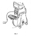
- FIG. 1 illustrates an disclosure of a surgical console 101 for a pneumatically powered ophthalmic surgical machine.
- the surgical console 101 may operate to assist a surgeon in performing various ophthalmic surgical procedures, such as phacoemulsification and vitrectomy.
- the surgical console 101 may include an internal monitor system, one or more controllers (e.g., proportional controllers), and tools (which may include phacoemulsification tools and/or pneumatic tools 103).
- the pneumatic tools 103 may include, for example, scissors, vitrectors, forceps, and injection or extraction modules. Other tools 103 may also be used.
- a compressed gas, such as nitrogen, may provide the power for pneumatic tools 103.
- the compressed gas may pass through the gas pressure monitor system, through one or more manifolds to the one or more proportional controllers, and through additional manifolds and/or tubing to tools 103.
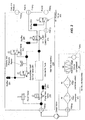
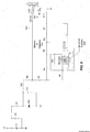
- FIG. 2 is a schematic of a pneumatic system for a pneumatically powered vitrectomy machine.
- the pneumatic system may include pump vent valve 205, output valve 210, mufflers 225, 230, 251, 253, manifold 235, and output ports A and B for respective pneumatic channels to power a pneumatic tool 103 (e.g., see FIG. 4 ).
- pump vent valve 205 may be a four-way valve.
- Valve 205 may include a solenoid that operates to move the valve to one of at least two positions. In one position, pressurized gas may pass through pump vent valve 205 and out of muffler 230. In another position, pump vent valve 205 may allow pressurized gas to pass through pump vent valve 205 to provide power to the tool 103.
- Pump vent valve 205 may be controlled by a controller (e.g., controller 300 as seen in FIG. 3 ).
- output valve 210 may be a four-way valve.
- Valve 210 may include a solenoid that operates to move the valve to one of at least two positions. In one position, the valve 210 may provide pressurized gas to output port A and vent pressurized gas from output port B (i.e., the "closed" position). In this position, pressurized gas can pass through output valve 210 to output port A where the pressurized gas provides pneumatic power to tool 103. Pressurized gas may also pass through output valve 210 and muffler 225 where it is exhausted to the atmosphere.
- output valve 210 allows pressurized gas to pass to output port B through valve 265 where the pressurized gas provides pneumatic power to tool 103. Pressurized gas may also pass through output valve 210 to muffler 225 where it is exhausted to the atmosphere.
- Output valve 210 may also be controlled by controller 300.
- the controller 300 may signal the solenoid valve to close during the closed position (a solenoid may act to move the valve to divert air through port A) and, upon discontinuing the signal (or sending an open signal), a spring (or other actuating mechanism) may return the valve to the open position (in which the valve is in a position to divert air to port B).
- the controller may apply the close signal for approximately the same amount of time that the signal is discontinued (the open position) or an open signal is applied.
- manifold assembly 235 may be machined out of a metal, such as aluminum, or plastic. Other materials are also contemplated. Manifold assembly 235 may be air tight, contain various fittings and couplings, and may be designed to withstand relatively high gas pressures. Manifold assembly 235 may be manufactured as a collection of individual pieces or may be manufactured as a single piece. For example, manifold assembly 235 may be machined from a single piece of aluminum. Mufflers 225, 230, 251, and 253 may suppress noise made by escaping gas.
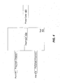
- FIG. 3 illustrates a schematic of a controller 300 and valves 205, 210, 261, 263, and 265 for a pneumatically powered vitrectomy machine.
- controller 300 may send control signals to valves 205, 210, 261, 263, and 265 via interfaces coupling the valves to the controller. Interfaces may include electrical conductors such as wires, buses, traces, etc.
- Controller 300 may be an integrated circuit capable of performing logic functions. Controller 300 may include an integrated circuit package with power, input, and output pins.
- controller 300 may be a valve controller or a targeted device controller. In such a case, controller 300 may perform specific control functions targeted to a specific device, such as a valve.
- controller 300 may be a microprocessor. Controller 300 may be programmable so that it can function to control valves as well as other components of the machine: In some disclosures, controller 300 may be a special purpose controller configured to control different valves that perform different functions.
- FIG. 4 illustrates a tool 103 (such as a vitrector) that may be attached to output ports A and B to act as a cutting device.
- the cutter 403 may be moved by a cylinder that in turn is moved by pressurized gas.
- the cylinder may oscillate as pressurized gas is alternately directed to output ports A and B.
- Such a vitrectomy device may be designed to operate at various cut rates (e.g., 1000 cuts per minute, 2500 cuts per minute, 5,000 cuts per minute, etc). Other cut rates are also contemplated.
- Port A and Port B may provide separate pneumatic channels (and a differential pressure between the two channels) for driving a tool 103.
- Alternating pressure pulses may be generated by a four way solenoid valve (e.g., vitrectomy cutter control valve 210) cycling pressure output between the two channels.
- the pressure differential may move a diaphragm 401 reciprocally inside the tool 103 (e.g., a probe) to move the linked probe cutter 403 on tool 103.
- a pressure bias in the two pneumatic channels (e.g., resulting in a higher pressure differential in either the open or close position of the valve) may affect the function and/or performance of the tool 103.
- pressure differentials may vary between different valves 210 in different consoles 101 resulting in diffculty providing a consistent operating pressure differential.
- software may be used to control the solenoid valve 210 open/closed timing (also known as the valve duty cycle).
- the valve duty cycle may be adjusted through calibration to better balance the differential pressure during both the open/closed positions of the valve. By adjusting the valve duty cycle, the time for delivering pressurized air to each pneumatic channel in a valve open/closed cycle may be lengthened or shortened to achieve a more consistent differential pressure throughout the valve cycle for smoother tool operation.
- valve 210 may provide pressurized air alternately to port A and port B at a rate of approximately 24 ms per cycle.
- a transition time to actually open and close the channels may use part of the cycle time.
- pneumatic channel 1 (i.e., via port A of control valve 210) may take 4 ms to open (while pneumatic channel 2 is closing) and 2 ms to close (while pneumatic channel 2 is opening) for a total transition time per 24 ms cycle of 6 ms.
- Other transition times are also contemplated.
- the valve may actually be open only 8 ms (12 ms - 4 ms) to channel 1 while closed to channel 2 and may be closed for 10 ms (12 ms - 2 ms) to channel 1 while open to channel 2.
- This valve timing difference of 8 ms vs. 10 ms in providing pressurized air to channel 1 and channel 2 can result in an unbalanced pressure differential in the two channels.
- the transition time may vary between various valves 210 (e.g., due to manufacturing variances in the valve 210)
- a fixed timing offset may not successfully counter the imbalance.
- a different valve may take 3 ms (instead of 4 ms) to open channel 1 (while pneumatic channel 2 is closing) and 2 ms to close channel 1 (while pneumatic channel 2 is opening).
- a valve duty cycle may be adjusted for individual valves and or console bases (e.g., to compensate for the different transition times of various valves and flow restriction/resistance variations of various consoles).
- an adjusted valve duty cycle may correspond to applying a signal to close the valve for approximately the same amount of time as the signal is not applied (corresponding to the open position).
- An adjustment of 1% may result in a 51% valve duty cycle that corresponds to applying a signal to close the valve for approximately 51 % of the total cycle time (and 49% of the total time no signal (or an open signal) is applied to open the valve).
- the longer 51% valve duty cycle may thus compensate, for example, for a valve that takes longer to close than it does to open and or a console that has higher flow restriction/resistance in the channel connecting to close position of the valve.
- a valve duty cycle value for the valve 210 may be stored in a memory 303 on the console 101 or tool 103.
- the memory 303 may include a DIP switch (a dual in-line package switch), a variable resistor, digital potentiometer, or an EEPROM (electrically erasable programmable read-only, memory).
- the valve duty cycle may be determined through trial and error and may be programmed or written into the memory 303 (e.g., at manufacture) or may be received, for example, through user interaction with the console 101 (e.g., as a value entered into a graphical user interface 107 of the console 101). The valve duty cycle may then be used by the surgical console 101 (e.g., controller 300 in surgical console 101) to control the open/close times of the valve 210.
- one or more DIP switches S1, S2, S3, etc. may be connected to a network of resistors (each of which may have a different resistance).
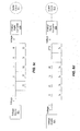
- FIGs. 5a and 5c illustrate disclosures with 5 DIP switches and FIGs. 5b and 6 illustrate embodiments with 6 DIP switches.
- FIG. 5d illustrates an disclosures with n DIP switches.
- Each DIP switch may be programmed with a 1 or 0 (switch on or off) to allow current through its corresponding resistor or to block current from its corresponding resistor.
- the network of resistors and DIP switches may have a total resistance that is based on the DIP switch settings.
- example resistance multiples e.g., in kilohms
- example network resistances may be 1, 2, 3, 4, 5, 6, 7, 8, 9, 10, 11, 12, 13, 14, 15, 16, 17, 18, 19, or 20 based on the settings of the 5 DIP switches (in the configuration shown, 32 DIP switch combinations may produce 20 network resistance values in increments of 1 along with 12 duplicates).
- 64 DIP switch combinations may produce 40 network resistance values in increments of 0.5 along with 24 duplicates (e.g., network resistance values or 1, 1.5, 2, 2.5, 3, 3.5, 4, 4.5, 5, 5.5, 6, 6.5, 7, 7.5, 8, 8.5, 9, 9.5, 10, 10.5, 11, 11.5, 12, 12.5, 13, 13.5, 14, 14.5, 15, 15.5, 16, 16.5, 17, 17.5, 18, 18.5, 19, 19.5, 20, and 20.5).
- network resistance values or 1, 1.5, 2, 2.5, 3, 3.5, 4, 4.5, 5, 5.5, 6, 6.5, 7, 7.5, 8, 8.5, 9, 9.5, 10, 10.5, 11, 11.5, 12, 12.5, 13, 13.5, 14, 14.5, 15, 15.5, 16, 16.5, 17, 17.5, 18, 18.5, 19, 19.5, 20, and 20.5.
- 5 DIP switch resistor network may include 32 DIP switch combinations to produce 32 network resistance values in increments of 1 without duplicates (e.g., resistance values of 1, 2, 3, 4, 5, 6, 7, 8, 9, 10, 11, 12, 13, 14, 15, 16, 17, 18, 19, 20, 21, 22, 23, 24, 25, 26, 27, 28, 29, 30, 31, and 32).
- an n DIP switch resistor network may include 2" DIP switch combinations to produce 2" network resistance values in increment of R without duplicates (e.g., resistance values are R, 2R, 3R, 4R, 5R, partly, 2"R).
- a known voltage (e.g., 5 volts) may be applied to the resister network (e.g., by voltage source 501) and a resulting voltage may be converted to a digital count 511 by an analog/digital converter 509.
- Software executing on the surgical console may use the digital count 511 to determine a corresponding valve duty cycle. For example, a table lookup may be performed on the digital count to determine a corresponding valve duty cycle value.
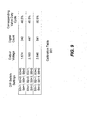
- a calibration table 901 (e.g., see FIG. 9 ) may be stored on the console with digital counts and corresponding valve duty cycle values.
- the DIP switches may be programmed in various on/off (1/0) positions to combine selected resistances in the network of resistors 505.
- the network of resistors may act as a voltage splitter to output a second voltage as a result of the first voltage applied to the network.
- the ADC 509 may convert the second voltage into a digital count 511.
- Voltage 2 may result in a digital count of 447 (e.g., corresponding to a voltage of 2.183 Volts).
- Software executing on the surgical console may use the digital count of 447 to determine a corresponding valve duty cycle (in this case 49.5%). For example, as seen in FIG.
- a look-up table may be accessed to determine a valve duty cycle corresponding to the digital count.
- the valve duty cycle may be determined and stored in a writable memory (e.g., an EEPROM).
- the EEPROM may be read instead of determining the valve duty cycle through use of the DIP switches.
- Using the EEPROM for subsequent uses may allow for a quicker determination of the valve duty cycle.
- Using the EEPROM may also prevent false values associated with the DIP switches being inadvertently switched or bumped or set by unauthorized personnel.
- a new valve duty cycle may be read into the EEPROM when the surgical console receives an indication that a new value is being determined (e.g., a user may enter a password in the user interface to authenticate the user and set the console for receiving a new valve duty cycle or a user may set a switch or press a button near the DIP switches indicating to the surgical console to detect and store a new valve duty cycle in the EEPROM (e.g., as determined from the DIP switches).
- an indication that a new value e.g., a user may enter a password in the user interface to authenticate the user and set the console for receiving a new valve duty cycle or a user may set a switch or press a button near the DIP switches indicating to the surgical console to detect and store a new valve duty cycle in the EEPROM (e.g., as determined from the DIP switches).
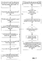
- FIG. 7 illustrates a method for determining a valve duty cycle for calibrating valve 210.
- the elements provided in the flowchart are illustrative only. Various provided elements may be omitted, additional elements may be added, and/or various elements may be performed in a different order than provided below.
- pneumatic ports of a valve 210 to be calibrated may be coupled to one or more pressure sensors for determining the pressure of each port (or a differential pressure between the ports) during operation of the valve 210.
- separate pressure sensors may be coupled to each port (A and B) or a differential pressure sensor may be coupled to both ports A and B. If using separate pressure sensors on each port, a differential pressure may be calculated using the pressure data from each port.
- tool 103 may be a pressure transducer box with the one or more pressure sensors coupling to the A and/or B ports through ports 105.
- the valve 210 may be tested while coupled to the surgical console (e.g., the pressure sensors may be coupled to the output pneumatic ports 105 of the surgical console 101).
- a cuts per minute setting may be set for the valve (e.g., 2500 cuts per minute).
- the pneumatic system valve duty cycle may be set to a default value (e.g., the calibration DIP switches may be set to 50% valve duty cycle which may result in no applied offset to the open/close valve timing).
- the DIP switch settings may be set using a calibration table 901 that relates DIP switch settings to valve duty cycles.
- pneumatic system including valve 210) may be operated for a given amount of time (e.g., 10 seconds).
- pressure data for the run may be detected through the pressure sensors.
- a footswitch treadle may be depressed to activate the pneumatic system.
- the pneumatic system may be operated for an extended time (e.g., 1 to 2 hours) especially if the pneumatic system and/or console is new.
- the extended operation prior to calibration may allow the system and/or console to settle out initial valve variations due to manufacturing, friction points, and other component interaction points (e.g., initial friction on new parts may be worn down as the new part interacts with other parts for the extended period).
- the pneumatic system may be discontinued after the initial run and then operated again for another set amount of time (e.g., 5 to 10 seconds) before taking the pressure data.
- a wait time (e.g., 5 to 10 seconds) may be applied between pneumatic system runs.
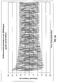
- FIG. 8a illustrates a plot of a possible pressure differential versus time for a pneumatic system.
- the pressure differentials may be +10 (68,95 kPa) and -13 (-89.63 kPa) psi (pounds per square inch) on the open/close positions (resulting in a pressure range 801 of approximately 23 psi).
- the lowest performance point may be the cycle interval time when the differential pressure difference between the pressure open and pressure closed is the lowest (i.e., when (abs(pressure open) + abs(pressure closed)) is at a minimum for the pressure data.
- a valve duty cycle to compensate for the pressure bias may be determined.
- the pressure bias appears to be approximately 3 (20,68 kPa) psi (associated with the -13 (-89,63 kPa) psi reading over the +10 (68,95 kPa) psi reading).
- a valve duty cycle that would result in approximately centering the pressure differential e.g., aimed at obtaining open/close pressure values of approximately +11.5 psi (78,29 kPa) and -11.5 psi (-78,29 kPa) at cycle interval time (T)
- T cycle interval time
- valve duty cycle to pressure differential adjustment ratio may be determined mathematically or through trial and error.
- the ratio may be 1% (valve duty cycle delta) to 0.86 psi (differential pressure change delta).
- the valve duty cycle may be rounded to a nearest increment (e.g., rounded to 51.5% if rounding to nearest increments of 0.5%).
- the pneumatic system may be programmed with the new valve duty cycle.
- the DIP switches (which may be physically accessible switches with on/off or 1/0 options) may be set in an on/off sequence that will produce a voltage corresponding to the determined valve duty cycle.
- the new valve duty cycle may be computed by the surgical console and/or entered into a graphical user interface of the surgical console.
- the pneumatic system may be operated again (e.g., 5 to 10 seconds).
- pressure data for the run may be detected through the pressure sensors.
- the pneumatic system may be discontinued after the initial run and then run again for another set amount of time (e.g., 5 to 10 seconds) before taking the pressure data.
- a wait time (e.g., 5 to 10 seconds) may be applied between pneumatic system runs.
- FIG. 8b illustrates a possible plot of pressure data after applying the new valve duty cycle.
- the pressure differential may now be approximately centered around 0 psi (0 kPa) such that the pressure differential in the closed position is approximately 11.5 psi (79.29 kPa) at the lowest performance point for the closed position and approximately -11.5 psi (-79.29 kPa) for the lowest performance point in the open position.
- pressure differentials, pressure range, and/or pressure bias may be compared to acceptable limits.
- the pressure differentials e.g., in the corrected case the differentials are approximately +11.5psi (79.29 kPa) and -11.5psi (-79.29 kPa) as seen in FIG. 8b
- a predetermined threshold for operation e.g., the absolute values of the differentials may be compared to a threshold of approximately 10 psi (68.95 kPa)
- the differential pressures absolute values for comparison purposes
- the threshold of 10psi 68.95 kPa
- a pressure bias (the pressure difference between the two channels) may also be determined and compared to a predetermined acceptable limit.
- the pressure bias may equal to abs(closed pressure) - abs(open pressure).
- a predetermined acceptable pressure bias limit of 1 psi (6.90 kPa) may be used (other pressure bias may also be used depending on the pneumatic system calibration).
- the total pressure range (abs(open pressure) + abs(closed pressure)) may be compared to a predetermined acceptable limit (e.g., a minimum 21.6 psi (148.93 kPa) of range).
- the total pressure range at a point of lowest performance for the pneumatic system may be compared to an acceptable total pressure range to determine if the pneumatic system has a leak or restriction. For example, if the total pressure range is ⁇ 21.6 psi (148.93 kPa), there may be a leakage or restriction in the system. Other total pressure range may also be used (different pneumatic system configurations may operate at different pressures and pressure ranges). If the total pressure range at the lowest performance point does not meet the minimum acceptable limit, the valve may be replaced and/or the pneumatic system may be checked. Also, if edges of pressure wave form are not smooth, but are wavy or have shifts, or are not expanding on both sides after the minimum performance points, the valve may need to be replaced.
- a new valve duty cycle may be used.
- open pressure and closed pressure may be differential pressures at a time of lowest performance for the pneumatic system.
- a valve duty cycle that is one increment above or below the previous valve duty cycle may be tried. If the previous closed pressure needs to be increased (to reduce the pressure bias toward the open position), the valve duty cycle may be increased to the next increment (e.g., from 51% to 51.5%) or vice versa.
- the new valve duty cycle may be determined by the surgical console and/or entered into a graphical user interface of the surgical console.
- DIP switches may be set to correspond to the new determined valve duty cycle. The new valve duty cycle may then be tested (e.g., by performing elements 713 to 719)
- valve/module may be installed.
- additional rounds of determining a new valve duty cycle or the DIP switches may be moved to correspond to another valve duty cycle above or below the previous one) may be performed.
- the calibration process may be concluded.
- the surgical console may use the determined valve duty cycle.
- the DIP switches and resistance network may relay the desired valve duty cycle (through a characteristic voltage) to the system console during operation. For example, a voltage from the resister network may be converted into a digital count through an analog/digital converter 509. The digital count may be processed by software executing on the surgical console and a corresponding valve duty cycle may be determined and used to modify the valve performance.
- the calibration process may be performed multiple times to insure repeatability of the calibration results with the determined valve duty cycle.
- the vitrectomy system may include one or more processors (e.g., controller 300).
- the controller 300 may include single processing devices or a plurality of processing devices.
- a processing device may be a microprocessor, controller (which may be a micro-controller), digital signal processor, microcomputer, central processing unit, field programmable gate array, programmable logic device, state machine, logic circuitry, control circuitry, analog circuitry, digital circuitry, and/or any device that manipulates signals (analog and/or digital) based on operational instructions.
- Memory coupled to and/or embedded in the processors may be a single memory device or a plurality of memory devices.
- Such a memory device may be a read-only memory, random access memory, volatile memory, non-volatile memory, static memory, dynamic memory, flash memory, cache memory, and/or any device that stores digital information.
- the processors implement one or more of its functions via a state machine, analog circuitry, digital circuitry, and/or logic circuitry
- the memory storing the corresponding operational instructions may be embedded within, or external to, the circuitry comprising the state machine, analog circuitry, digital circuitry, and/or logic circuitry.
- the memory may store, and the processor may execute, operational instructions corresponding to at least some of the elements illustrated and described in association with, for example, FIG. 7 .
Description
- The present invention generally pertains to calibration. More particularly, but not by way of limitation, the present invention pertains to calibration for a pneumatic surgical system.
- Vitreo-retinal procedures include a variety of surgical procedures performed to restore, preserve, and enhance vision. Vitreo-retinal procedures are appropriate to treat many serious conditions of the back of the eye. Vitreo-retinal procedures treat conditions such as age-related macular degeneration (AMD), diabetic retinopathy and diabetic vitreous hemorrhage, macular hole, retinal detachment, epiretinal membrane, CM Vretinitis, and many other ophthalmic conditions.
- The vitreous is a normally clear, gel-like substance that fills the center of the eye. It makes up approximately 2/3 of the eye's volume, giving it form and shape before birth. Certain problems affecting the back of the eye may require a vitrectomy, or surgical removal of the vitreous.
- A vitrectomy may be performed to clear blood and debris from the eye, to remove scar tissue, or to alleviate traction on the retina. Blood, inflammatory cells, debris, and scar tissue obscure light as it passes through the eye to the retina, resulting in blurred vision. The vitreous is also removed if it is pulling or tugging the retina from its normal position. Some of the most common eye conditions that require vitrectomy include complications from diabetic retinopathy such as retinal detachment or bleeding, macular hole, retinal detachment, pre-retinal membrane fibrosis, bleeding inside the eye (vitreous hemorrhage), injury or infection, and certain problems related to previous eye surgery. Vitrectomies may be performed in the anterior or posterior portions of the eye. While an anterior vitrectomy may be a planned procedure performed in such settings as traumatic cataract removal or secondary IOL (intraocular lens) placement, an anterior vitrectomy is most often an unplanned addition to a cataract surgery when vitreous is inadvertently prolapsing into the anterior segment after a rupture of the posterior capsule.
- The retinal surgeon performs a vitrectomy with a microscope and special lenses designed to provide a clear image of the back of the eye. Several tiny incisions just a few millimeters in length are made on the sclera. The retinal surgeon inserts microsurgical instruments through the incisions such as a fiber optic light source to illuminate inside the eye, an infusion line to maintain the eye's shape during surgery, and instruments to cut and remove the vitreous.
- In a vitrectomy, the surgeon creates three tiny incisions in the eye for three separate instruments. These incisions are placed in the pars plana of the eye, which is located just behind the iris but in front of the retina. The instruments which pass through these incisions include a light pipe, an infusion port, and the vitrectomy cutting device. The light pipe is the equivalent of a microscopic high-intensity flashlight for use within the eye. The infusion port is required to replace fluid in the eye and maintain proper pressure within the eye. The vitrector, or cutting device, works like a tiny guillotine, with an oscillating microscopic cutter to remove the vitreous gel in a controlled fashion. This prevents significant traction on the retina during the removal of the vitreous humor.
- The surgical machine used to perform a vitrectomy and other surgeries on the anterior and/or posterior of the eye is very complex. Typically, such an ophthalmic surgical machine includes a main console to which the numerous different tools are attached. The main console provides power to and controls the operation of the attached tools. The main console may also be used for performing other ophthalmic procedures such as phacoemulsification.
- The attached tools typically include probes, scissors, forceps, illuminators, vitrectors, and infusion lines. Each of these tools is typically attached to the main surgical console. A computer in the main surgical console monitors and controls the operation of these tools. These tools also get their power from the main surgical console. Some of these tools are electrically powered while others are pneumatically powered.
- In order to provide pneumatic power to the various tools, the main surgical console has a pneumatic or air distribution module. This pneumatic module conditions and supplies compressed air or gas to power the tools. Typically, the pneumatic module is connected to a cylinder that contains compressed gas. The pneumatic module may provide the proper gas pressure to operate the attached tools properly.
-
WO 2008 147429 is considered to be the closest prior art and discloses the preamble ofindependent apparatus claim 1 andmethod claim 11. - In various disclosures, a surgical console may include a pneumatic valve (e.g., a four way solenoid valve) with at least two ports operable to alternately provide pressurized gas to drive a pneumatic tool (such as a vitrectomy probe) coupled to the surgical console. The surgical console may further include a controller operable to control and adjust the valve open/close times according to a valve duty cycle. The valve may switch between ports (valve open time for a first port and valve close time for a second port) such that a total valve time may approximately equal the valve open time plus the valve close time. The valve duty cycle may indicate a percentage (e.g., 50%) of the total valve time for the controller to signal the valve to open.
- Because different valve open/close timings can lead to a loss in operating pressure, an adjustment may be made to the valve duty cycle so that signal timing for the open and/or closed valve positions will result in open and closed operating pressures above a predetermined threshold. For example, the adjusted valve duty cycle may be approximately equal to a previous valve duty cycle + (((abs(open pressure) - abs(closed pressure))/2) * (valve duty cycle delta / differential pressure change delta)) where the previous valve duty cycle is the valve duty cycle during testing, open pressure and closed pressure are differential pressures for the ports at respective open and closed times during one cycle of the valve, and the valve duty cycle delta / differential pressure change delta is a ratio of valve duty cycle change to resulting differential pressure change (for example, in the valve open pressure). For calculating the new valve duty cycle, the open pressure and closed pressure for the port may be taken during a lowest performance point for the pneumatic system (e.g., when the absolute pressure difference between the open pressure and closed pressure is the lowest such that (abs(open pressure) + abs(closed pressure)) is at a minimum for the measured pressure data). Once determined, the valve duty cycle may be stored on a memory accessible by the controller for future use.
- In some embodiments, a valve duty cycle may be input into the system through a series of DIP switch settings. For example, the surgical console may include DIP switches and resistors coupled together such that the DIP switches are configurable to combine one or more of the resistors in a resistor network. The DIP switches may be set such that upon applying an input voltage to the resistor network, an output voltage of the resistor network is indicative of a valve duty cycle. In some embodiments, the surgical console may include an analog to digital converter operable to convert the output voltage to a digital value that software executing on the surgical console can use to determine a valve duty cycle (e.g., through the use of a look-up table that associates the digital value with an associated valve duty cycle).
- For a more complete understanding of the present invention, reference is made to the following description taken in conjunction with the accompanying drawings in which:
-
FIG. 1 illustrates a surgical console; -
FIG. 2 illustrates a diagram of a pneumatic system; -
FIG. 3 illustrates a controller for the pneumatic valves; -
FIG. 4 illustrates a diagram of a pneumatic tool; -
FIGs. 5a-6 illustrate various embodiments of a DIP switch and resistor network; -
FIG. 7 illustrates a flowchart of a method for calibrating a pneumatics system, according to an embodiment; -
FIGs. 8a-8b illustrate pressure data for a pneumatic valve -
FIG. 9 illustrates a calibration table. - It is to be understood that both the foregoing general description and the following detailed description are exemplary and explanatory only and are intended to provide a further explanation of the present invention as claimed.
-
FIG. 1 illustrates an disclosure of asurgical console 101 for a pneumatically powered ophthalmic surgical machine. Thesurgical console 101 may operate to assist a surgeon in performing various ophthalmic surgical procedures, such as phacoemulsification and vitrectomy. Thesurgical console 101 may include an internal monitor system, one or more controllers (e.g., proportional controllers), and tools (which may include phacoemulsification tools and/or pneumatic tools 103). Thepneumatic tools 103 may include, for example, scissors, vitrectors, forceps, and injection or extraction modules.Other tools 103 may also be used. A compressed gas, such as nitrogen, may provide the power forpneumatic tools 103. The compressed gas may pass through the gas pressure monitor system, through one or more manifolds to the one or more proportional controllers, and through additional manifolds and/or tubing totools 103. -
FIG. 2 is a schematic of a pneumatic system for a pneumatically powered vitrectomy machine. InFIG. 2 , the pneumatic system may includepump vent valve 205,output valve 210,mufflers FIG. 4 ). - In some disclosures, pump
vent valve 205 may be a four-way valve.Valve 205 may include a solenoid that operates to move the valve to one of at least two positions. In one position, pressurized gas may pass throughpump vent valve 205 and out ofmuffler 230. In another position, pumpvent valve 205 may allow pressurized gas to pass throughpump vent valve 205 to provide power to thetool 103.Pump vent valve 205 may be controlled by a controller (e.g.,controller 300 as seen inFIG. 3 ). - In one embodiments,
output valve 210 may be a four-way valve.Valve 210 may include a solenoid that operates to move the valve to one of at least two positions. In one position, thevalve 210 may provide pressurized gas to output port A and vent pressurized gas from output port B (i.e., the "closed" position). In this position, pressurized gas can pass throughoutput valve 210 to output port A where the pressurized gas provides pneumatic power totool 103. Pressurized gas may also pass throughoutput valve 210 andmuffler 225 where it is exhausted to the atmosphere. In another position (i.e., the "open" position),output valve 210 allows pressurized gas to pass to output port B throughvalve 265 where the pressurized gas provides pneumatic power totool 103. Pressurized gas may also pass throughoutput valve 210 tomuffler 225 where it is exhausted to the atmosphere.Output valve 210 may also be controlled bycontroller 300. In some embodiments, thecontroller 300 may signal the solenoid valve to close during the closed position (a solenoid may act to move the valve to divert air through port A) and, upon discontinuing the signal (or sending an open signal), a spring (or other actuating mechanism) may return the valve to the open position (in which the valve is in a position to divert air to port B). During a valve duty cycle of 50%, the controller may apply the close signal for approximately the same amount of time that the signal is discontinued (the open position) or an open signal is applied. - In some disclosures,
manifold assembly 235 may be machined out of a metal, such as aluminum, or plastic. Other materials are also contemplated.Manifold assembly 235 may be air tight, contain various fittings and couplings, and may be designed to withstand relatively high gas pressures.Manifold assembly 235 may be manufactured as a collection of individual pieces or may be manufactured as a single piece. For example,manifold assembly 235 may be machined from a single piece of aluminum.Mufflers -
FIG. 3 illustrates a schematic of acontroller 300 andvalves controller 300 may send control signals tovalves Controller 300 may be an integrated circuit capable of performing logic functions.Controller 300 may include an integrated circuit package with power, input, and output pins. In various disclosures,controller 300 may be a valve controller or a targeted device controller. In such a case,controller 300 may perform specific control functions targeted to a specific device, such as a valve. In some disclosures,controller 300 may be a microprocessor.Controller 300 may be programmable so that it can function to control valves as well as other components of the machine: In some disclosures,controller 300 may be a special purpose controller configured to control different valves that perform different functions. -
FIG. 4 illustrates a tool 103 (such as a vitrector) that may be attached to output ports A and B to act as a cutting device. Thecutter 403 may be moved by a cylinder that in turn is moved by pressurized gas. The cylinder may oscillate as pressurized gas is alternately directed to output ports A and B. Such a vitrectomy device may be designed to operate at various cut rates (e.g., 1000 cuts per minute, 2500 cuts per minute, 5,000 cuts per minute, etc). Other cut rates are also contemplated. Port A and Port B may provide separate pneumatic channels (and a differential pressure between the two channels) for driving atool 103. Alternating pressure pulses may be generated by a four way solenoid valve (e.g., vitrectomy cutter control valve 210) cycling pressure output between the two channels. As seen inFIG. 4 , the pressure differential may move adiaphragm 401 reciprocally inside the tool 103 (e.g., a probe) to move the linkedprobe cutter 403 ontool 103. A pressure bias in the two pneumatic channels (e.g., resulting in a higher pressure differential in either the open or close position of the valve) may affect the function and/or performance of thetool 103. Because of various factors (e.g., valve to valve variations and flow restriction/resistance variations in the two channels from console to console), pressure differentials may vary betweendifferent valves 210 indifferent consoles 101 resulting in diffculty providing a consistent operating pressure differential. To control the pressure differentials of the two pneumatic channel output, software may be used to control thesolenoid valve 210 open/closed timing (also known as the valve duty cycle). The valve duty cycle may be adjusted through calibration to better balance the differential pressure during both the open/closed positions of the valve. By adjusting the valve duty cycle, the time for delivering pressurized air to each pneumatic channel in a valve open/closed cycle may be lengthened or shortened to achieve a more consistent differential pressure throughout the valve cycle for smoother tool operation. - For example, at 2500 cuts per minute probe rate,
valve 210 may provide pressurized air alternately to port A and port B at a rate of approximately 24 ms per cycle. To obtain a cut rate of 2500 cuts per minute, the two pneumatic channels may cycle on/off every 24 ms (2500 cuts / min or 1 min / 2500 cuts * 60 seconds / 1 min = 0.024 seconds / cut = 24 ms / cut), which may open for 12ms to each channel. A transition time to actually open and close the channels may use part of the cycle time. For example, pneumatic channel 1 (i.e., via port A of control valve 210) may take 4 ms to open (whilepneumatic channel 2 is closing) and 2 ms to close (whilepneumatic channel 2 is opening) for a total transition time per 24 ms cycle of 6 ms. Other transition times are also contemplated. Because of the transition time, the valve may actually be open only 8 ms (12 ms - 4 ms) tochannel 1 while closed tochannel 2 and may be closed for 10 ms (12 ms - 2 ms) tochannel 1 while open tochannel 2. This valve timing difference of 8 ms vs. 10 ms in providing pressurized air tochannel 1 andchannel 2 can result in an unbalanced pressure differential in the two channels. In some disclosures, it may be desirable for the open time durations of the two channels to be approximately the same (e.g., in the case of 2500 cuts/minute, actually open for approximately (24 ms - 6 ms) / 2 = 9 ms). If the transition timings are constant for allvalves 210 then software control may adjust the valve duty cycle to achieve approximately equal actual open time durations for both channels. In this example, software may adjust the nominal open time to 13 ms forchannel channel 2. Thus, for this example, excluding transition time, the actual open time ofchannel 1 may be 13 ms - 4 ms = 9 ms and the actual open time ofchannel 2 may be 11 ms - 2 ms = 9 ms (similar to channel 1). However, because the transition time may vary between various valves 210 (e.g., due to manufacturing variances in the valve 210), a fixed timing offset may not successfully counter the imbalance. For example, a different valve may take 3 ms (instead of 4 ms) to open channel 1 (whilepneumatic channel 2 is closing) and 2 ms to close channel 1 (whilepneumatic channel 2 is opening). Applying the same software control valve duty cycle (e.g., 13 ms nominal open time forchannel pneumatic channel 1 may be 13 ms - 3 ms = 10 ms and the actual open time forchannel 2 may be 11 ms - 2 ms = 9 ms. Therefore, in this example,pneumatic channel 1 may remain actually open 1 ms or 11 % longer thanpneumatic channel 2. The difference may result in an uneven power balance between the two pneumatic channels which may result in a lower effective cutting rate/power. Similarly a fixed timing offset may not successfully counter the imbalance caused by the flow restriction/resistance variations in the two channels from console to console. - In some embodiments, a valve duty cycle may be adjusted for individual valves and or console bases (e.g., to compensate for the different transition times of various valves and flow restriction/resistance variations of various consoles). By applying an adjusted valve duty cycle to the cycle times for the pneumatic channels, the pneumatic channels may be actuated during the total cycle time to have approximately equal actual open times. As noted above, a 50% valve duty cycle may correspond to applying a signal to close the valve for approximately the same amount of time as the signal is not applied (corresponding to the open position). An adjustment of 1% may result in a 51% valve duty cycle that corresponds to applying a signal to close the valve for approximately 51 % of the total cycle time (and 49% of the total time no signal (or an open signal) is applied to open the valve). The longer 51% valve duty cycle may thus compensate, for example, for a valve that takes longer to close than it does to open and or a console that has higher flow restriction/resistance in the channel connecting to close position of the valve.
- In some embodiments, a valve duty cycle value for the
valve 210 may be stored in amemory 303 on theconsole 101 ortool 103. Thememory 303 may include a DIP switch (a dual in-line package switch), a variable resistor, digital potentiometer, or an EEPROM (electrically erasable programmable read-only, memory). In some disclosures, the valve duty cycle may be determined through trial and error and may be programmed or written into the memory 303 (e.g., at manufacture) or may be received, for example, through user interaction with the console 101 (e.g., as a value entered into agraphical user interface 107 of the console 101). The valve duty cycle may then be used by the surgical console 101 (e.g.,controller 300 in surgical console 101) to control the open/close times of thevalve 210. - As seen in
FIG. 5a-6 , one or more DIP switches S1, S2, S3, etc. may be connected to a network of resistors (each of which may have a different resistance).FIGs. 5a and5c illustrate disclosures with 5 DIP switches andFIGs. 5b and6 illustrate embodiments with 6 DIP switches.FIG. 5d illustrates an disclosures with n DIP switches. Each DIP switch may be programmed with a 1 or 0 (switch on or off) to allow current through its corresponding resistor or to block current from its corresponding resistor. The network of resistors and DIP switches may have a total resistance that is based on the DIP switch settings. For example, with 6 DIP switches (each with a corresponding resistor), the network of resistors may be configured to have a resistance selected from 2^6=64 possible resistances. Combinations of the DIP switch settings may therefore produce different resistant values of the resistor network. For example, above each resistor inFIGs. 5a-6 are example resistance multiples (e.g., in kilohms) (other resistances are also possible). As seen inFIG. 5a , example network resistances may be 1, 2, 3, 4, 5, 6, 7, 8, 9, 10, 11, 12, 13, 14, 15, 16, 17, 18, 19, or 20 based on the settings of the 5 DIP switches (in the configuration shown, 32 DIP switch combinations may produce 20 network resistance values in increments of 1 along with 12 duplicates). Other configurations are also possible (e.g., different resistance values, different DIP switch placements, etc). InFIG. 5b , 64 DIP switch combinations may produce 40 network resistance values in increments of 0.5 along with 24 duplicates (e.g., network resistance values or 1, 1.5, 2, 2.5, 3, 3.5, 4, 4.5, 5, 5.5, 6, 6.5, 7, 7.5, 8, 8.5, 9, 9.5, 10, 10.5, 11, 11.5, 12, 12.5, 13, 13.5, 14, 14.5, 15, 15.5, 16, 16.5, 17, 17.5, 18, 18.5, 19, 19.5, 20, and 20.5). As seen inFIG. 5c ,5 DIP switch resistor network may include 32 DIP switch combinations to produce 32 network resistance values in increments of 1 without duplicates (e.g., resistance values of 1, 2, 3, 4, 5, 6, 7, 8, 9, 10, 11, 12, 13, 14, 15, 16, 17, 18, 19, 20, 21, 22, 23, 24, 25, 26, 27, 28, 29, 30, 31, and 32). As seen inFIG. 5d , an n DIP switch resistor network may include 2" DIP switch combinations to produce 2" network resistance values in increment of R without duplicates (e.g., resistance values are R, 2R, 3R, 4R, 5R, ......, 2"R). A known voltage (e.g., 5 volts) may be applied to the resister network (e.g., by voltage source 501) and a resulting voltage may be converted to adigital count 511 by an analog/digital converter 509. Software executing on the surgical console may use thedigital count 511 to determine a corresponding valve duty cycle. For example, a table lookup may be performed on the digital count to determine a corresponding valve duty cycle value. In some disclosures, a calibration table 901 (e.g., seeFIG. 9 ) may be stored on the console with digital counts and corresponding valve duty cycle values. - As noted above, the DIP switches (e.g., in the set of DIP switches 503) may be programmed in various on/off (1/0) positions to combine selected resistances in the network of
resistors 505. The network of resistors may act as a voltage splitter to output a second voltage as a result of the first voltage applied to the network. TheADC 509 may convert the second voltage into adigital count 511. For example,Voltage 2 may result in a digital count of 447 (e.g., corresponding to a voltage of 2.183 Volts). Software executing on the surgical console may use the digital count of 447 to determine a corresponding valve duty cycle (in this case 49.5%). For example, as seen inFIG. 9 , a look-up table may be accessed to determine a valve duty cycle corresponding to the digital count. In some embodiments, the valve duty cycle may be determined and stored in a writable memory (e.g., an EEPROM). During subsequent uses of the surgical consoles, the EEPROM may be read instead of determining the valve duty cycle through use of the DIP switches. Using the EEPROM for subsequent uses may allow for a quicker determination of the valve duty cycle. Using the EEPROM may also prevent false values associated with the DIP switches being inadvertently switched or bumped or set by unauthorized personnel. In some embodiments, a new valve duty cycle may be read into the EEPROM when the surgical console receives an indication that a new value is being determined (e.g., a user may enter a password in the user interface to authenticate the user and set the console for receiving a new valve duty cycle or a user may set a switch or press a button near the DIP switches indicating to the surgical console to detect and store a new valve duty cycle in the EEPROM (e.g., as determined from the DIP switches). -
FIG. 7 illustrates a method for determining a valve duty cycle for calibratingvalve 210. The elements provided in the flowchart are illustrative only. Various provided elements may be omitted, additional elements may be added, and/or various elements may be performed in a different order than provided below. - At 701, pneumatic ports of a
valve 210 to be calibrated may be coupled to one or more pressure sensors for determining the pressure of each port (or a differential pressure between the ports) during operation of thevalve 210. For example, separate pressure sensors may be coupled to each port (A and B) or a differential pressure sensor may be coupled to both ports A and B. If using separate pressure sensors on each port, a differential pressure may be calculated using the pressure data from each port. As seen inFIG. 1 ,tool 103 may be a pressure transducer box with the one or more pressure sensors coupling to the A and/or B ports throughports 105. Thevalve 210 may be tested while coupled to the surgical console (e.g., the pressure sensors may be coupled to the outputpneumatic ports 105 of the surgical console 101). A cuts per minute setting may be set for the valve (e.g., 2500 cuts per minute). - At 703, the pneumatic system valve duty cycle may be set to a default value (e.g., the calibration DIP switches may be set to 50% valve duty cycle which may result in no applied offset to the open/close valve timing). The DIP switch settings may be set using a calibration table 901 that relates DIP switch settings to valve duty cycles.
- At 705, pneumatic system (including valve 210) may be operated for a given amount of time (e.g., 10 seconds). During the pneumatic system operation, pressure data for the run may be detected through the pressure sensors. A footswitch treadle may be depressed to activate the pneumatic system. In some embodiments, the pneumatic system may be operated for an extended time (e.g., 1 to 2 hours) especially if the pneumatic system and/or console is new. The extended operation prior to calibration may allow the system and/or console to settle out initial valve variations due to manufacturing, friction points, and other component interaction points (e.g., initial friction on new parts may be worn down as the new part interacts with other parts for the extended period). The pneumatic system may be discontinued after the initial run and then operated again for another set amount of time (e.g., 5 to 10 seconds) before taking the pressure data. A wait time (e.g., 5 to 10 seconds) may be applied between pneumatic system runs.
- At 707, pressure differentials and pressure range between the open/close valve positions may be determined.
FIG. 8a illustrates a plot of a possible pressure differential versus time for a pneumatic system. As seen inFIG. 8a , at cycle interval time (T), the pressure differentials may be +10 (68,95 kPa) and -13 (-89.63 kPa) psi (pounds per square inch) on the open/close positions (resulting in apressure range 801 of approximately 23 psi). The lowest performance point may be the cycle interval time when the differential pressure difference between the pressure open and pressure closed is the lowest (i.e., when (abs(pressure open) + abs(pressure closed)) is at a minimum for the pressure data. In the case shown inFIG. 8a , there is a noticeable dip in pressures for the open and closed position at cycle interval time (T). - At 709, a valve duty cycle to compensate for the pressure bias may be determined. In the pressure data shown in
FIG. 8a , at cycle interval time (T), the pressure bias appears to be approximately 3 (20,68 kPa) psi (associated with the -13 (-89,63 kPa) psi reading over the +10 (68,95 kPa) psi reading). A valve duty cycle that would result in approximately centering the pressure differential (e.g., aimed at obtaining open/close pressure values of approximately +11.5 psi (78,29 kPa) and -11.5 psi (-78,29 kPa) at cycle interval time (T)) may be determined. Determining the valve duty cycle to center the pressure differentials at the lowest performance point of the pneumatic system may insure that the pneumatic system has sufficient pressure to operate in both the open and closed positions at its lowest performance point (the valve duty cycle may also result in improved performance at the other operating points of the pneumatic system). While several examples herein determine a valve duty cycle around the lowest performance point, a valve duty cycle may also be determined using other points in the pressure data. Determining a valve duty cycle may be calculated as follows:
- Where open pressure and closed pressure are taken at a time of lowest performance for the pneumatic system (e.g., time T in the current example) and where abs() represents the absolute valve. In some disclosures, the valve duty cycle to pressure differential adjustment ratio may be determined mathematically or through trial and error. For example, the ratio may be 1% (valve duty cycle delta) to 0.86 psi (differential pressure change delta).
- In the current example:


- Thus, the pressure on the close side (currently +10 psi (68.95 kPa)) may be increased to 11.5 psi (79.29 kPa) with the new valve duty cycle of 51.744% (10 psi + 1.744% * (0.86 psi (68.95kPa) / 1%) = 11.5 psi (79.29 kPa)) and the open side may be shifted to -11.5 psi (-79.29 kPa) (-13 psi (-89.63 kPa) + 1.744% * (0.86 psi (5.93 kPa) / 1%) = -11.5 psi (-79.29 kPa)). In some embodiments, the valve duty cycle may be rounded to a nearest increment (e.g., rounded to 51.5% if rounding to nearest increments of 0.5%).
- At 711, the pneumatic system may be programmed with the new valve duty cycle. For example, the DIP switches (which may be physically accessible switches with on/off or 1/0 options) may be set in an on/off sequence that will produce a voltage corresponding to the determined valve duty cycle. In some embodiments, the new valve duty cycle may be computed by the surgical console and/or entered into a graphical user interface of the surgical console.
- At 713, the pneumatic system may be operated again (e.g., 5 to 10 seconds). During the pneumatic system operation, pressure data for the run may be detected through the pressure sensors. In some disclosures, the pneumatic system may be discontinued after the initial run and then run again for another set amount of time (e.g., 5 to 10 seconds) before taking the pressure data. In some disclosures, a wait time (e.g., 5 to 10 seconds) may be applied between pneumatic system runs.
- At 715, pressure differentials and pressure range between the open/close valve positions may be determined again.
FIG. 8b illustrates a possible plot of pressure data after applying the new valve duty cycle. As seen inFIG. 8b , the pressure differential may now be approximately centered around 0 psi (0 kPa) such that the pressure differential in the closed position is approximately 11.5 psi (79.29 kPa) at the lowest performance point for the closed position and approximately -11.5 psi (-79.29 kPa) for the lowest performance point in the open position. - At 717, pressure differentials, pressure range, and/or pressure bias may be compared to acceptable limits. In some disclosures, the pressure differentials (e.g., in the corrected case the differentials are approximately +11.5psi (79.29 kPa) and -11.5psi (-79.29 kPa) as seen in
FIG. 8b ), may be compared to a predetermined threshold for operation (e.g., the absolute values of the differentials may be compared to a threshold of approximately 10 psi (68.95 kPa)). In the corrected case shown inFIG. 8b , the differential pressures (absolute values for comparison purposes) are greater than the threshold of 10psi (68.95 kPa). In some embodiments, a pressure bias (the pressure difference between the two channels) may also be determined and compared to a predetermined acceptable limit. For example, the pressure bias may equal to abs(closed pressure) - abs(open pressure). After calibration, a predetermined acceptable pressure bias limit of 1 psi (6.90 kPa) may be used (other pressure bias may also be used depending on the pneumatic system calibration). As another example, the total pressure range (abs(open pressure) + abs(closed pressure)) may be compared to a predetermined acceptable limit (e.g., a minimum 21.6 psi (148.93 kPa) of range). In some disclosures, the total pressure range at a point of lowest performance for the pneumatic system may be compared to an acceptable total pressure range to determine if the pneumatic system has a leak or restriction. For example, if the total pressure range is < 21.6 psi (148.93 kPa), there may be a leakage or restriction in the system. Other total pressure range may also be used (different pneumatic system configurations may operate at different pressures and pressure ranges). If the total pressure range at the lowest performance point does not meet the minimum acceptable limit, the valve may be replaced and/or the pneumatic system may be checked. Also, if edges of pressure wave form are not smooth, but are wavy or have shifts, or are not expanding on both sides after the minimum performance points, the valve may need to be replaced. - At 719, if the total pressure range or pressure bias is out of the acceptable range, a new valve duty cycle may be used. In some disclosures, the new valve duty cycle may be recalculated. For example:

- Where open pressure and closed pressure may be differential pressures at a time of lowest performance for the pneumatic system. In some disclosures, instead of using the equation, a valve duty cycle that is one increment above or below the previous valve duty cycle may be tried. If the previous closed pressure needs to be increased (to reduce the pressure bias toward the open position), the valve duty cycle may be increased to the next increment (e.g., from 51% to 51.5%) or vice versa. In some embodiments, the new valve duty cycle may be determined by the surgical console and/or entered into a graphical user interface of the surgical console. In some embodiments, DIP switches may be set to correspond to the new determined valve duty cycle. The new valve duty cycle may then be tested (e.g., by performing
elements 713 to 719) - At 721, if the valve has been tested more than a set number of times (e.g., twice) and the total pressure range or pressure bias is still out of the acceptable range, a different valve/module may be installed. In some disclosures, additional rounds of determining a new valve duty cycle (or the DIP switches may be moved to correspond to another valve duty cycle above or below the previous one) may be performed.
- At 723, if the total pressure range and the pressure bias from 717 are within the acceptable ranges, the calibration process may be concluded. The surgical console may use the determined valve duty cycle. In some embodiments, the DIP switches and resistance network may relay the desired valve duty cycle (through a characteristic voltage) to the system console during operation. For example, a voltage from the resister network may be converted into a digital count through an analog/
digital converter 509. The digital count may be processed by software executing on the surgical console and a corresponding valve duty cycle may be determined and used to modify the valve performance. In some disclosures, the calibration process may be performed multiple times to insure repeatability of the calibration results with the determined valve duty cycle. - In some embodiments, the vitrectomy system may include one or more processors (e.g., controller 300). The
controller 300 may include single processing devices or a plurality of processing devices. Such a processing device may be a microprocessor, controller (which may be a micro-controller), digital signal processor, microcomputer, central processing unit, field programmable gate array, programmable logic device, state machine, logic circuitry, control circuitry, analog circuitry, digital circuitry, and/or any device that manipulates signals (analog and/or digital) based on operational instructions. Memory coupled to and/or embedded in the processors may be a single memory device or a plurality of memory devices. Such a memory device may be a read-only memory, random access memory, volatile memory, non-volatile memory, static memory, dynamic memory, flash memory, cache memory, and/or any device that stores digital information. Note that when the processors implement one or more of its functions via a state machine, analog circuitry, digital circuitry, and/or logic circuitry, the memory storing the corresponding operational instructions may be embedded within, or external to, the circuitry comprising the state machine, analog circuitry, digital circuitry, and/or logic circuitry. The memory may store, and the processor may execute, operational instructions corresponding to at least some of the elements illustrated and described in association with, for example,FIG. 7 .
Claims (17)
- A surgical console (101), comprising:a valve (205, 210);at least a first port (A) and a second port (B) coupled to the valve, wherein the valve is configured to provide pressurized gas alternately to each of the first port and the second port to drive a pneumatic tool (103) coupled to the surgical console;at least one pressure sensor adapted to measure operating pressure data of the first and second port;a controller (300) coupled to the valve, wherein the controller is operable to control the valve open and close times, wherein a valve open time corresponds to a time to open a first port and wherein a valve close time corresponds to a time for closing the first port, wherein closing the first port coincides with opening a second port such that pressurized air is being directed by the valve either through the first port or the second port;wherein the controller is configured to adjust the valve open/close times according to a valve duty cycle; characterized in thatthe valve duty cycle adjustment is determined by analyzing the operating pressure data for the open and closed valve positions, such that the valve duty cycle with the adjustment centers a pressure differential, between the first port and the second port, around zero.
- The surgical console of claim 1, wherein the valve (205) is a four-way solenoid valve.
- The surgical console of claim 1, further comprising a pneumatic tool (103) coupled to the surgical console (101), wherein the pneumatic tool is a vitrectomy cutter.
- The surgical console of claim 1, wherein the valve duty cycle is stored on a memory (303) accessible by the controller (300).
- The surgical console of claim 1, wherein a total valve time equals approximately the valve open time plus the valve close time for a valve cycle, and wherein the valve duty cycle is a percentage of the total valve time for the controller (300) to signal the valve to direct gas through the first port.
- The surgical console of claim 1, wherein the valve duty cycle adjustment is determined using pressure data during testing of the surgical console, wherein the valve duty cycle is approximately equal to a previous valve duty cycle + (((abs(open pressure) - abs(closed pressure))/2) * (valve duty cycle delta / differential pressure change delta)) where the previous valve duty cycle is the valve duty cycle during testing, open pressure and closed pressure are differential pressures for the port for one cycle of the valve, and wherein the valve duty cycle delta / differential pressure change delta is a ratio of valve duty cycle change to resulting differential pressure change.
- The surgical console of claim 6, wherein the open pressure and closed pressure for the port are taken during a lowest performance point for the pneumatic system.
- The surgical console of claim 7, wherein the lowest performance point is the point when the absolute differential pressure difference between the open pressure and close pressure is the lowest such that (abs(pressure open) + abs(pressure closed)) is at a minimum for the measured pressure data.
- The surgical console of claim 1, further comprising a plurality of DIP switches (503) and a plurality of resistors (505), wherein the DIP switches are configurable to combine one or more of the plurality of resistors in a resistor network such that upon applying an input voltage to the resistor network, an output voltage of the resistor network is indicative of a valve duty cycle.
- The surgical console of claim 9, further comprising an analog to digital converter (509) to convert the output voltage to a digital value, wherein software executing on the surgical console is operable to determine a valve duty cycle that corresponds to the digital count through a look-up table.
- A method of calibrating a surgical pneumatic system, comprising:operating a pneumatic system (705) comprising a pneumatic valve (210) configured to cycle between an open position and a closed position wherein pressurized gas is directed at a first port (A) when the valve is in the open position and wherein pressurized gas is directed at a second port (B) when the valve is in the closed position;measuring pressures (707) output by the pneumatic valve, characterized in that the measured pressure data comprises an open differential pressure corresponding to a differential pressure between the first port and the second port during the open position and a closed differential pressure corresponding to a differential pressure between the first port and the second port during the closed position; and software executed on a surgical consolecalculates a new valve duty cycle (719), wherein the new valve duty cycle is approximately equal to a previous valve duty cycle + (((abs(open pressure) - abs(closed pressure))/2) * (valve duty cycle delta / pressure differential change delta)) where the previous valve duty cycle is the valve duty cycle during operation of the pneumatic system while measuring the pressures, open pressure and closed pressure are the measured differential pressures for the port during a corresponding open position and closed position of one cycle of the valve, andwherein the valve duty cycle delta / pressure differential change delta is a ratio of valve duty cycle change to resulting differential pressure change.
- The method of claim 11, wherein the open pressure and closed pressure for the port are taken during a lowest performance point during the measured pressures for the pneumatic system.
- The method of claim 11, further comprising using the new valve duty cycle to modify the valve open position timing.
- The method of claim 13, further comprising:operating (705) the pneumatic system and measuring pressures output by the pneumatic valve;calculating a total pressure range, wherein the total pressure range is approximately equal to the sum of absolute values of the open pressure and the closed pressure; anddetermining (717) if the total pressure range is greater than a predetermined total pressure range limit.
- The method of claim 13, further comprising:operating (705) the pneumatic system and measuring pressures output by the pneumatic valve;calculating a pressure bias, wherein the pressure bias is approximately equal to abs(closed pressure) - abs(open pressure);determining if the pressure bias is less than a predetermined pressure bias limit.
- The method of claim 15, wherein the open pressure and the closed pressure are the differential pressures during a lowest performance point during pressure measuring.
- The method of claim 16, wherein the lowest performance point is the point when the pressure difference between the open pressure and closed pressure is the lowest such that (abs(pressure open) + abs(pressure closed)) is at a minimum for the measured pressure data.
Applications Claiming Priority (2)
| Application Number | Priority Date | Filing Date | Title |
|---|---|---|---|
| US23843109P | 2009-08-31 | 2009-08-31 | |
| PCT/US2010/045136 WO2011025658A1 (en) | 2009-08-31 | 2010-08-11 | Pneumatic pressure output control by drive valve duty cycle calibration |
Publications (2)
| Publication Number | Publication Date |
|---|---|
| EP2473144A1 EP2473144A1 (en) | 2012-07-11 |
| EP2473144B1 true EP2473144B1 (en) | 2015-10-14 |
Family
ID=43033172
Family Applications (1)
| Application Number | Title | Priority Date | Filing Date |
|---|---|---|---|
| EP10745088.4A Active EP2473144B1 (en) | 2009-08-31 | 2010-08-11 | Pneumatic pressure output control by drive valve duty cycle calibration |
Country Status (8)
| Country | Link |
|---|---|
| US (2) | US8818564B2 (en) |
| EP (1) | EP2473144B1 (en) |
| JP (1) | JP5770731B2 (en) |
| CN (1) | CN102497841B (en) |
| AU (1) | AU2010286834B2 (en) |
| CA (1) | CA2770487C (en) |
| ES (1) | ES2551581T3 (en) |
| WO (1) | WO2011025658A1 (en) |
Families Citing this family (23)
| Publication number | Priority date | Publication date | Assignee | Title |
|---|---|---|---|---|
| AU2010286834B2 (en) | 2009-08-31 | 2015-06-04 | Alcon Inc. | Pneumatic pressure output control by drive valve duty cycle calibration |
| AU2010328590B2 (en) * | 2009-12-10 | 2015-09-17 | Alcon Inc. | Systems and methods for dynamic pneumatic valve driver |
| US8821524B2 (en) * | 2010-05-27 | 2014-09-02 | Alcon Research, Ltd. | Feedback control of on/off pneumatic actuators |
| WO2012064864A1 (en) | 2010-11-09 | 2012-05-18 | Aegea Medical Inc. | Positioning method and apparatus for delivering vapor to the uterus |
| US8403917B2 (en) * | 2010-12-29 | 2013-03-26 | Bausch & Lomb Incorporated | Pneumatic surgical instrument detection system |
| US8808318B2 (en) | 2011-02-28 | 2014-08-19 | Alcon Research, Ltd. | Surgical probe with increased fluid flow |
| US9060841B2 (en) | 2011-08-31 | 2015-06-23 | Alcon Research, Ltd. | Enhanced flow vitrectomy probe |
| US9662060B2 (en) | 2011-10-07 | 2017-05-30 | Aegea Medical Inc. | Integrity testing method and apparatus for delivering vapor to the uterus |
| NL2009424C2 (en) | 2012-09-06 | 2014-03-10 | D O R C Dutch Ophthalmic Res Ct International B V | Irrigation/aspiration system, cartridge, pump unit, surgical machine, method for controlling. |
| US9498376B2 (en) | 2012-12-17 | 2016-11-22 | Abbott Medical Optics Inc. | Vitrectomy surgical apparatus with cut timing based on pressures encountered |
| US9486358B2 (en) | 2012-12-17 | 2016-11-08 | Abbott Medical Optics Inc. | Vitrectomy surgical apparatus |
| US9271867B2 (en) | 2012-12-17 | 2016-03-01 | Abbott Medical Optics Inc. | Vitrectomy surgical apparatus with regulating of material processed |
| US9615969B2 (en) | 2012-12-18 | 2017-04-11 | Novartis Ag | Multi-port vitrectomy probe with dual cutting edges |
| EP3134044B1 (en) | 2014-04-23 | 2018-10-03 | Johnson & Johnson Surgical Vision, Inc. | Vitrectomy surgical apparatus employing multisensor pressure feedback |
| US10179019B2 (en) | 2014-05-22 | 2019-01-15 | Aegea Medical Inc. | Integrity testing method and apparatus for delivering vapor to the uterus |
| EP3145425A4 (en) | 2014-05-22 | 2018-02-14 | Aegea Medical, Inc. | Systems and methods for performing endometrial ablation |
| US9693898B2 (en) | 2014-11-19 | 2017-07-04 | Novartis Ag | Double-acting vitreous probe with contoured port |
| CN107438454B (en) * | 2015-04-13 | 2020-07-31 | 爱尔康公司 | High-speed pneumatic valve |
| EP3416551B1 (en) | 2016-02-19 | 2022-10-12 | Aegea Medical Inc. | Apparatus for determining the integrity of a bodily cavity |
| CN106642557A (en) * | 2016-12-05 | 2017-05-10 | 广东美的制冷设备有限公司 | Water tank water discharge switch noise reduction control method and system and air conditioner |
| US11540942B2 (en) | 2018-07-26 | 2023-01-03 | Alcon Inc. | Redundant pneumatic circuit for reliability enhancement of vitrectomy instruments |
| US11642243B2 (en) | 2018-12-10 | 2023-05-09 | Alcon Inc. | Methods of solenoid valve control optimization |
| AU2020418184A1 (en) | 2020-01-03 | 2022-08-18 | Lensar, Inc. | Patient interface devices and methods and systems for combined sonic and laser applications |
Family Cites Families (170)
| Publication number | Priority date | Publication date | Assignee | Title |
|---|---|---|---|---|
| US812162A (en) * | 1905-12-18 | 1906-02-06 | Thomas Bemis | Pneumatic tube for store service. |
| US2016746A (en) * | 1933-08-25 | 1935-10-08 | Thomas H Ireland | Fluid heater |
| NL73735C (en) * | 1949-06-30 | |||
| GB792397A (en) | 1956-05-09 | 1958-03-26 | Pneumatic Components Ltd | Improvements in or relating to tyre inflation hose equipment |
| US3084674A (en) * | 1961-07-20 | 1963-04-09 | Ingersoll Rand Co | Pneumatic system for multiple nut runner |
| US3601588A (en) | 1966-05-23 | 1971-08-24 | Foxboro Co | Method and apparatus for adaptive control |
| FR1506385A (en) | 1966-09-16 | 1967-12-22 | Sud Aviation | Method of attenuation and electro-hydraulic vibration attenuator for rotary wing aerodyne |
| US3515155A (en) | 1967-02-24 | 1970-06-02 | Air Reduction | Gas mixture proportioner |
| US3646727A (en) * | 1969-06-02 | 1972-03-07 | Erich A Wachsmuth | Automatic compressor drain system |
| GB1281196A (en) * | 1969-11-20 | 1972-07-12 | Westland Aircraft Ltd | Improvements in or relating to pressure control systems |
| FR2117726B1 (en) | 1970-12-10 | 1973-12-07 | Aquitaine Petrole | |
| US3815604A (en) * | 1972-06-19 | 1974-06-11 | Malley C O | Apparatus for intraocular surgery |
| US3867934A (en) * | 1973-05-04 | 1975-02-25 | Veriflo Corp | Pressure monitor for a lung ventilator |
| US3854382A (en) | 1973-06-20 | 1974-12-17 | Sperry Rand Ltd | Hydraulic actuator controls |
| GB1417299A (en) | 1973-09-18 | 1975-12-10 | Gulde Regelarmatuhren Kg | Method and apparatus for safe-guarding pipe-lines against inadmissibly high internal pressure by a control valve with a pneumatic drive |
| US4011869A (en) * | 1975-08-01 | 1977-03-15 | David Kopf Instruments | Tubular cutting instrument |
| GB1518720A (en) | 1975-11-21 | 1978-07-26 | Ishikawajima Harima Heavy Ind | Hydraulic servomechanism |
| US4077567A (en) * | 1976-06-18 | 1978-03-07 | Universal Pneumatic Controls, Inc. | Pneumatic temperature reset differential pressure controller |
| US4323064A (en) * | 1976-10-26 | 1982-04-06 | Puritan-Bennett Corporation | Volume ventilator |
| US4086804A (en) * | 1976-10-26 | 1978-05-02 | Sperry Rand Corporation | Precision pneumatic pressure supply system |
| US4168707A (en) * | 1977-06-13 | 1979-09-25 | Douvas Nicholas G | Control apparatus for microsurgical instruments |
| US4335867A (en) * | 1977-10-06 | 1982-06-22 | Bihlmaier John A | Pneumatic-hydraulic actuator system |
| US4368734A (en) * | 1978-01-27 | 1983-01-18 | Surgical Design Corp. | Surgical instrument |
| US4255789A (en) * | 1978-02-27 | 1981-03-10 | The Bendix Corporation | Microprocessor-based electronic engine control system |
| DE2811345C2 (en) * | 1978-03-16 | 1986-12-11 | Knorr-Bremse AG, 8000 München | Pressure regulators for pneumatic pressures, in particular in vehicles |
| JPS5584858A (en) * | 1978-12-18 | 1980-06-26 | Nippon Denso Co Ltd | Engine control |
| FR2455766B1 (en) * | 1979-05-02 | 1985-09-06 | Intertechnique Sa | PNEUMATIC DEVICE AND INSTALLATION FOR CREATING PRESSURE OR FLOW CYCLES |
| US4331130A (en) * | 1980-06-27 | 1982-05-25 | Lewicky Andrew O | Securing device to the cornea to prevent anterior chamber prolapse |
| US4590935A (en) * | 1981-11-02 | 1986-05-27 | Optikon Oftalmologia, S.P.A. | Control system for intraocular surgical device |
| GB2140871A (en) | 1983-06-03 | 1984-12-05 | Bowthorpe Hellermann Ltd | Piston and cylinder actuator control |
| US4679583A (en) * | 1984-04-19 | 1987-07-14 | Robertshaw Controls Company | Pneumatic control system, control means therefor and method of making the same |
| BR8403165A (en) * | 1984-06-28 | 1984-11-27 | Jaime Roizenblatt | PNEUMATIC MODULE FOR INTRAOCULAR MICROSURGERY |
| US4678459A (en) * | 1984-07-23 | 1987-07-07 | E-Z-Em, Inc. | Irrigating, cutting and aspirating system for percutaneous surgery |
| US4706687A (en) * | 1985-02-28 | 1987-11-17 | Alcon Instrumentation, Inc. | Linear suction control system |
| US4757814A (en) * | 1985-02-28 | 1988-07-19 | Alcon Laboratories, Inc. | Proportional control for pneumatic cutting device |
| US4650462A (en) * | 1985-07-29 | 1987-03-17 | Minnesota Mining And Manufacturing Company | Irrigation system |
| US4810242A (en) * | 1985-09-26 | 1989-03-07 | Alcon Laboratories Inc. | Surgical cassette proximity sensing and latching apparatus |
| US4790816A (en) * | 1985-09-26 | 1988-12-13 | Allon Laboratories, Inc. | Surgical cassette proximity sensing and latching apparatus |
| US4770654A (en) * | 1985-09-26 | 1988-09-13 | Alcon Laboratories Inc. | Multimedia apparatus for driving powered surgical instruments |
| US4622503A (en) * | 1985-09-26 | 1986-11-11 | Medical Instrument Development Laboratories, Inc. | Variable pneumatic output means for use with ophthalmic micro-surgical instruments |
| US4696298A (en) * | 1985-11-19 | 1987-09-29 | Storz Instrument Company | Vitrectomy cutting mechanism |
| US4840111A (en) * | 1986-01-31 | 1989-06-20 | Moog Inc. | Energy-conserving regenerative-flow valves for hydraulic servomotors |
| US4933843A (en) * | 1986-11-06 | 1990-06-12 | Storz Instrument Company | Control system for ophthalmic surgical instruments |
| EP0305382B1 (en) | 1987-03-18 | 1996-09-11 | Monroe Auto Equipment Company | Method and apparatus for absorbing mechanical shock |
| DE3708989C2 (en) | 1987-03-19 | 1993-10-14 | Festo Kg | Control device for a piston displaceable in a double-acting cylinder |
| US5239861A (en) * | 1988-12-23 | 1993-08-31 | Kabushiki Kaisha Komatsu Seisakusho | Device for indicating contamination degree of hydraulic circuit and method of judging the contamination degree |
| US5092178A (en) | 1989-04-28 | 1992-03-03 | Pneumo Abex Corporation | Differential pressure sensor mechanisms |
| US5019035A (en) * | 1989-06-07 | 1991-05-28 | Alcon Surgical, Inc. | Cutting assembly for surgical cutting instrument |
| US5106364A (en) * | 1989-07-07 | 1992-04-21 | Kabushiki Kaisha Topcon | Surgical cutter |
| DE3925405A1 (en) | 1989-08-01 | 1991-02-07 | Vdo Schindling | Pressure control unit esp. for vehicle windscreen wiper - has solenoid controlled relief valve to control pressure in load stage |
| US5020315A (en) | 1989-08-08 | 1991-06-04 | United Technologies Corporation | Multiple function fuel valve and system |
| US5024654A (en) * | 1989-10-02 | 1991-06-18 | Alcon Surgical, Inc. | Insulated infusion and aspiration probe |
| US5047008A (en) * | 1989-10-27 | 1991-09-10 | Storz Instrument Company | Vitrectomy probe |
| US5176628A (en) * | 1989-10-27 | 1993-01-05 | Alcon Surgical, Inc. | Vitreous cutter |
| US5417246A (en) * | 1989-10-27 | 1995-05-23 | American Cyanamid Company | Pneumatic controls for ophthalmic surgical system |
| US4985027A (en) * | 1990-02-26 | 1991-01-15 | Dressel Thomas D | Soft tissue aspiration device and method |
| US5138564A (en) * | 1990-07-31 | 1992-08-11 | Xerox Corporation | Automatic encoder calibration |
| US5094260A (en) * | 1990-10-26 | 1992-03-10 | Alcon Surgical, Inc. | Proportional valve and pressure control system |
| EP0596967A4 (en) * | 1991-07-31 | 1994-10-19 | Mentor O & O Inc | Controlling operation of handpieces during ophthalmic surgery. |
| US5154207A (en) | 1991-08-02 | 1992-10-13 | Mosier Industries, Inc. | Pressure control valve and transducer package |
| FI90035C (en) * | 1992-02-07 | 1993-12-27 | Valmet Paper Machinery Inc | RULL STOPPING OCH FOERFARANDE FOER ANVAENDNING DAERAV |
| US5217465A (en) * | 1992-02-28 | 1993-06-08 | Alcon Surgical, Inc. | Flexible and steerable aspiration tip for microsurgery |
| DE4232586A1 (en) | 1992-09-23 | 1994-03-24 | Mannesmann Ag | Switching valve with regulation of output pressure - has inlet valve stage that closes when output pressure exceeds reference with vent valve stage opening to control pressure |
| DE4241846C2 (en) | 1992-12-11 | 1996-09-26 | Danfoss As | Hydraulic system |
| US5403276A (en) * | 1993-02-16 | 1995-04-04 | Danek Medical, Inc. | Apparatus for minimally invasive tissue removal |
| US5829335A (en) * | 1993-05-11 | 1998-11-03 | Mannesmann Rexroth Gmbh | Control for hydraulic drive or actuator |
| DE4315626C1 (en) | 1993-05-11 | 1994-07-14 | Rexroth Mannesmann Gmbh | Control for a hydraulic drive |
| JP2595450B2 (en) * | 1993-09-08 | 1997-04-02 | 日精樹脂工業株式会社 | Method and apparatus for detecting abnormality of hydraulic system in molding machine |
| US5550685A (en) * | 1993-10-22 | 1996-08-27 | Syquest Technology, Inc. | Applying an adaptive feed-forward algorithm as a frequency selective filter in a closed loop disk drive servo system in order to compensate for periodic perturbations which otherwise appear in the servo system position error signal |
| US5380280A (en) | 1993-11-12 | 1995-01-10 | Peterson; Erik W. | Aspiration system having pressure-controlled and flow-controlled modes |
| US5457625A (en) * | 1994-04-13 | 1995-10-10 | The M. W. Kellogg Company | Maximizing process production rates using permanent constraints |
| US5487725A (en) | 1994-05-12 | 1996-01-30 | Syntec, Inc. | Pneumatic vitrectomy for retinal attachment |
| US5437241A (en) * | 1994-06-08 | 1995-08-01 | Pall Corporation | Differential pressure indicator |
| JP3679143B2 (en) * | 1994-06-30 | 2005-08-03 | 株式会社ニデック | Perfusion suction device |
| US5571248A (en) * | 1995-03-10 | 1996-11-05 | General Motors Corporation | Pressure regulator |
| US5630827A (en) * | 1995-06-19 | 1997-05-20 | Dutch Ophthalmic Research Center International Bv | Vitreous removing apparatus |
| US5587536A (en) * | 1995-08-17 | 1996-12-24 | Rasmussen; John | Differential pressure sensing device for pneumatic cylinders |
| US5674194A (en) * | 1995-10-25 | 1997-10-07 | Alcon Laboratories Inc. | Process control system |
| US5989262A (en) * | 1996-04-15 | 1999-11-23 | Josephberg; Robert Gary | Sutureless pars plana vitrectomy tool |
| WO1998023212A1 (en) * | 1996-11-27 | 1998-06-04 | Armand Maaskamp | Needle for surgical use |
| US5808396A (en) * | 1996-12-18 | 1998-09-15 | Alcon Laboratories, Inc. | System and method for tuning and controlling an ultrasonic handpiece |
| US5791142A (en) * | 1997-03-27 | 1998-08-11 | Husco International, Inc. | Hydraulic control valve system with split pressure compensator |
| SE507552C2 (en) | 1997-04-23 | 1998-06-22 | Rudolf Westerberg Ab | Tvåhandsmanöversystem |
| JPH10339301A (en) | 1997-06-09 | 1998-12-22 | Smc Corp | Control method of automatically controlled pneumatic device and automatically controlled pneumatic device |
| US5846257A (en) * | 1997-08-15 | 1998-12-08 | Nexus Medical System, Inc. Llc | Pressure sensor for a surgical system |
| US6425883B1 (en) * | 1998-05-08 | 2002-07-30 | Circuit Tree Medical, Inc. | Method and apparatus for controlling vacuum as a function of ultrasonic power in an ophthalmic phaco aspirator |
| DE19821420C1 (en) | 1998-05-13 | 1999-10-21 | Haldex Bremsen Gmbh & Co Kg | Pressurized air device for automobile pneumatic circuits |
| US6575264B2 (en) * | 1999-01-29 | 2003-06-10 | Dana Corporation | Precision electro-hydraulic actuator positioning system |
| AU4701499A (en) | 1999-06-22 | 2001-01-09 | Scieran Technologies, Inc. | An apparatus and method for performing ophthalmic procedures |
| US6162187A (en) | 1999-08-02 | 2000-12-19 | Ethicon Endo-Surgery, Inc. | Fluid collection apparatus for a surgical device |
| US6514268B2 (en) * | 1999-08-30 | 2003-02-04 | Alcon Universal Ltd. | Method of operating microsurgical instruments |
| US6155233A (en) * | 1999-09-07 | 2000-12-05 | Fasco Controls Corp. | Combination pressure sensor and regulator for direct injection diesel engine fuel system |
| US6575990B1 (en) * | 1999-10-21 | 2003-06-10 | Medical Instrument Development Laboratories, Inc. | High speed vitreous cutting system |
| NL1013376C2 (en) | 1999-10-22 | 2001-04-24 | Dutch Ophthalmic Res Ct B V | Surgical cutting tool. |
| CA2724266C (en) * | 2000-02-29 | 2012-12-04 | Gen-Probe Incorporated | Fluid dispense and liquid surface verification system and method |
| US6443947B1 (en) | 2000-03-01 | 2002-09-03 | Alexei Marko | Device for thermal ablation of a cavity |
| US20010037689A1 (en) | 2000-03-08 | 2001-11-08 | Krouth Terrance F. | Hydraulic actuator piston measurement apparatus and method |
| US6450966B1 (en) * | 2000-05-03 | 2002-09-17 | Datex-Ohmeda, Inc. | Method for non-invasive blood pressure cuff identification using deflation pressure measurements |
| US6504474B1 (en) | 2000-07-12 | 2003-01-07 | Deere & Company | Method and apparatus for detecting a restricted or bypassed transmission oil filter |
| US6485436B1 (en) * | 2000-08-10 | 2002-11-26 | Csaba Truckai | Pressure-assisted biopsy needle apparatus and technique |
| US6561999B1 (en) * | 2000-09-29 | 2003-05-13 | Alcon Universal Ltd. | Surgical cassette and consumables for combined ophthalmic surgical procedure |
| US6618628B1 (en) * | 2000-10-05 | 2003-09-09 | Karl A. Davlin | Distributed input/output control systems and methods |
| JP4021141B2 (en) | 2000-10-20 | 2007-12-12 | 株式会社ニデック | Vitreous surgery device |
| US6758824B1 (en) | 2000-11-06 | 2004-07-06 | Suros Surgical Systems, Inc. | Biopsy apparatus |
| US6471853B1 (en) * | 2000-11-22 | 2002-10-29 | Pti Technologies, Inc. | Prognostic health monitoring of fluidic systems using MEMS technology |
| US6568416B2 (en) * | 2001-02-28 | 2003-05-27 | Brian L. Andersen | Fluid flow control system, fluid delivery and control system for a fluid delivery line, and method for controlling pressure oscillations within fluid of a fluid delivery line |
| US6779541B2 (en) * | 2001-10-12 | 2004-08-24 | Smc Kabushiki Kaisha | Fluid pressure regulator |
| US7470277B2 (en) * | 2001-10-16 | 2008-12-30 | Alcon, Inc. | Simultaneous proportional control of surgical parameters in a microsurgical system |
| CN100580251C (en) | 2001-11-19 | 2010-01-13 | 卢克汽车-液压系统两合公司 | Determination of the piston machine stroke |
| US6892745B2 (en) | 2002-04-10 | 2005-05-17 | Honeywell International Inc. | Flow control valve with integral sensor and controller and related method |
| US6678584B2 (en) * | 2002-05-03 | 2004-01-13 | Fisher Controls International Llc | Method and apparatus for performing diagnostics in a control loop of a control valve |
| US6999853B2 (en) | 2002-05-03 | 2006-02-14 | Fisher Controls International Llc. | Methods and apparatus for operating and performing diagnostics in a control loop of a control valve |
| US20030226809A1 (en) | 2002-06-06 | 2003-12-11 | Detroit Diesel Corporation | Method and apparatus for determining oil filter life |
| DE10247869B4 (en) | 2002-10-14 | 2007-02-08 | Imi Norgren Gmbh | Pressure medium actuated working cylinder |
| US20040186484A1 (en) | 2003-01-29 | 2004-09-23 | Edwin Ryan | Small gauge surgical instrument with support device |
| US8202277B2 (en) | 2003-01-29 | 2012-06-19 | Edwin Ryan | Small gauge surgical instrument with support device |
| US7219691B2 (en) | 2003-02-07 | 2007-05-22 | Fisher Controls International Llc | Control valve positioner mounting system |
| DE10341477A1 (en) | 2003-09-05 | 2005-03-31 | Riehle, Rainer, Dipl.-Ing. | Sound generator for generating in pipelines of a water or gas supply system propagatable sound pulses |
| US20050245909A1 (en) | 2004-04-29 | 2005-11-03 | Mccary Brian D | Embedded data chip in a surgical handpiece |
| US7775052B2 (en) | 2004-05-07 | 2010-08-17 | Delavan Inc | Active combustion control system for gas turbine engines |
| US7337041B2 (en) | 2004-06-14 | 2008-02-26 | Fisher Controls International | Feedback control methods and apparatus for electro-pneumatic control systems |
| US7283321B1 (en) | 2004-10-08 | 2007-10-16 | Maxtor Corporation | Disk drives and methods allowing for dual stage actuator adaptive seek control and microactuator gain calibration |
| US7352287B2 (en) | 2005-01-07 | 2008-04-01 | Veris Industries, Llc | Pneumatic controller |
| US20060271082A1 (en) * | 2005-05-31 | 2006-11-30 | Kirchhevel G Lamar | Calibrated surgical probe |
| DE202005009670U1 (en) | 2005-06-17 | 2005-09-01 | Sieber, Dieter | Pneumatic drive muffler, has pressure sensor that produces warning signal and switches off pneumatic drive when impact pressure within cavity increased due to increased contamination of muffler reaches predetermined limit pressure |
| DE102005043367B4 (en) | 2005-09-12 | 2016-09-08 | Laeis Gmbh | Control device and control method for a piston-cylinder arrangement |
| US7326183B2 (en) | 2005-09-28 | 2008-02-05 | Alcon, Inc. | Intraocular pressure control |
| US7600405B2 (en) | 2005-10-11 | 2009-10-13 | Alcon, Inc. | Microsurgical probe |
| EP1949042B1 (en) | 2005-10-21 | 2015-11-11 | Lonza AG | Mass flow rate control system |
| US9047787B2 (en) | 2005-11-30 | 2015-06-02 | Terumo Cardiovascular Systems Corp. | Perfusion method and apparatus |
| US8187293B2 (en) | 2006-02-06 | 2012-05-29 | Novartis Ag | Microsurgical instrument |
| US7774287B2 (en) | 2006-03-14 | 2010-08-10 | Asml Netherlands B.V. | System and method for moving a component through a setpoint profile, lithographic apparatus and device manufacturing method |
| US20070282262A1 (en) * | 2006-05-19 | 2007-12-06 | Alcon, Inc. | Surgical system having integral pneumatic manifolds |
| US20070270746A1 (en) * | 2006-05-19 | 2007-11-22 | Alcon, Inc. | Surgical system having pneumatic manifolds with integral air cylinders |
| US9180232B2 (en) * | 2006-05-19 | 2015-11-10 | Novartis Ag | Surgical system having manifolds with integral pneumatic accumulators |
| US20080125695A1 (en) * | 2006-06-23 | 2008-05-29 | Hopkins Mark A | Reflux control in microsurgical system |
| DE102006030034A1 (en) | 2006-06-29 | 2008-01-03 | Zf Friedrichshafen Ag | Device for controlling a fluid-operated double-acting adjusting cylinder |
| US7708734B2 (en) | 2006-06-30 | 2010-05-04 | Alcon, Inc. | Method for dynamically adjusting operation of a surgical handpiece |
| US7640119B2 (en) | 2006-06-30 | 2009-12-29 | Alcon, Inc. | System for dynamically adjusting operation of a surgical handpiece |
| FR2905594B1 (en) | 2006-09-08 | 2008-12-05 | Corneal Ind Soc Par Actions Si | PNEUMATIC VITREOTOME |
| US20080082077A1 (en) * | 2006-09-29 | 2008-04-03 | David Lloyd Williams | System and method for flow rate control |
| US8679241B2 (en) * | 2006-10-30 | 2014-03-25 | Novartis Ag | Gas pressure monitor for pneumatic surgical machine |
| US8038692B2 (en) | 2006-10-31 | 2011-10-18 | Novartis Ag | Modular design for ophthalmic surgical probe |
| US8105405B2 (en) * | 2006-11-07 | 2012-01-31 | Novartis Ag | Quick release filter assembly for pneumatic surgical machine |
| US7628054B2 (en) | 2006-11-09 | 2009-12-08 | Abbott Medical Optics Inc. | Calibration utility for non-linear measurement system |
| US8162000B2 (en) * | 2006-12-13 | 2012-04-24 | Novartis Ag | Adjustable pneumatic system for a surgical machine |
| US9241830B2 (en) | 2006-12-15 | 2016-01-26 | Novartis Ag | Pressure monitor for pneumatic vitrectomy machine |
| US8312800B2 (en) * | 2006-12-21 | 2012-11-20 | Novartis Ag | Pneumatic system for a vitrector |
| CN101568306A (en) | 2006-12-22 | 2009-10-28 | 爱尔康研究有限公司 | Method of operating a microsurgical instrument |
| US8157145B2 (en) | 2007-05-31 | 2012-04-17 | Ethicon Endo-Surgery, Inc. | Pneumatically powered surgical cutting and fastening instrument with electrical feedback |
| US8080029B2 (en) * | 2007-09-21 | 2011-12-20 | Novartis Ag | System for actuation of a vitreous cutter |
| US8460324B2 (en) * | 2008-04-15 | 2013-06-11 | Abbott Medical Optics Inc. | High speed pneumatic vitrectomy control |
| US20090287233A1 (en) | 2008-05-15 | 2009-11-19 | Huculak John C | Small Gauge Mechanical Tissue Cutter/Aspirator Probe For Glaucoma Surgery |
| JP5231902B2 (en) * | 2008-09-02 | 2013-07-10 | 株式会社ニデック | Vitreous surgery device |
| US8328835B2 (en) | 2008-12-08 | 2012-12-11 | Bausch & Lomb Incorporated | System for operating and controlling a pneumatically driven vitrectomy probe |
| CN102282517B (en) | 2008-12-11 | 2016-10-19 | 诺格伦有限公司 | For the method and apparatus controlling fluid operated actuator |
| DE102009006533B4 (en) | 2009-01-28 | 2011-06-30 | Siemens Aktiengesellschaft, 80333 | Actuator with an open / close valve |
| US20100305596A1 (en) | 2009-05-26 | 2010-12-02 | Erik William Peterson | Non-linear cut-rate multiplier for vitreous cutter |
| US20100312169A1 (en) | 2009-06-03 | 2010-12-09 | Auld Jack R | Method of operating a vitrectomy probe |
| DE102009032897B4 (en) | 2009-07-10 | 2013-09-19 | Stabilus Gmbh | Piston-cylinder assembly |
| AU2010286834B2 (en) | 2009-08-31 | 2015-06-04 | Alcon Inc. | Pneumatic pressure output control by drive valve duty cycle calibration |
| US8666556B2 (en) | 2009-12-10 | 2014-03-04 | Alcon Research, Ltd. | Systems and methods for dynamic feedforward |
| AU2010328590B2 (en) | 2009-12-10 | 2015-09-17 | Alcon Inc. | Systems and methods for dynamic pneumatic valve driver |
| DE102010028762A1 (en) | 2010-05-07 | 2011-11-10 | Zf Friedrichshafen Ag | Device for determining an operating state of at least one bidirectionally actuable hydraulic adjusting device of a switching element of a transmission device |
| US8821524B2 (en) * | 2010-05-27 | 2014-09-02 | Alcon Research, Ltd. | Feedback control of on/off pneumatic actuators |
| US8920078B2 (en) | 2010-06-03 | 2014-12-30 | Jason Woolever | Blower controller for pneumatic conveyance of granular materials |
| US9101442B2 (en) | 2010-12-15 | 2015-08-11 | Alcon Research, Ltd. | Reduced friction vitrectomy probe |
| US8888802B2 (en) | 2010-12-21 | 2014-11-18 | Alcon Research, Ltd. | Vitrectomy probe with adjustable cutter port size |
| US9101441B2 (en) | 2010-12-21 | 2015-08-11 | Alcon Research, Ltd. | Vitrectomy probe with adjustable cutter port size |
| US8808318B2 (en) | 2011-02-28 | 2014-08-19 | Alcon Research, Ltd. | Surgical probe with increased fluid flow |
-
2010
- 2010-08-11 AU AU2010286834A patent/AU2010286834B2/en active Active
- 2010-08-11 JP JP2012527889A patent/JP5770731B2/en active Active
- 2010-08-11 ES ES10745088.4T patent/ES2551581T3/en active Active
- 2010-08-11 EP EP10745088.4A patent/EP2473144B1/en active Active
- 2010-08-11 US US12/854,281 patent/US8818564B2/en active Active
- 2010-08-11 CN CN201080038468.XA patent/CN102497841B/en active Active
- 2010-08-11 CA CA2770487A patent/CA2770487C/en active Active
- 2010-08-11 WO PCT/US2010/045136 patent/WO2011025658A1/en active Application Filing
-
2014
- 2014-07-08 US US14/325,763 patent/US9937077B2/en active Active
Also Published As
| Publication number | Publication date |
|---|---|
| AU2010286834B2 (en) | 2015-06-04 |
| US20140350583A1 (en) | 2014-11-27 |
| JP5770731B2 (en) | 2015-08-26 |
| US9937077B2 (en) | 2018-04-10 |
| ES2551581T3 (en) | 2015-11-20 |
| EP2473144A1 (en) | 2012-07-11 |
| CA2770487C (en) | 2018-01-09 |
| US8818564B2 (en) | 2014-08-26 |
| AU2010286834A1 (en) | 2012-03-08 |
| US20110054508A1 (en) | 2011-03-03 |
| CN102497841A (en) | 2012-06-13 |
| CN102497841B (en) | 2014-12-10 |
| CA2770487A1 (en) | 2011-03-03 |
| WO2011025658A1 (en) | 2011-03-03 |
| JP2013503024A (en) | 2013-01-31 |
Similar Documents
| Publication | Publication Date | Title |
|---|---|---|
| EP2473144B1 (en) | Pneumatic pressure output control by drive valve duty cycle calibration | |
| EP2509549B1 (en) | Systems and methods for dynamic pneumatic valve driver | |
| US8162000B2 (en) | Adjustable pneumatic system for a surgical machine | |
| CN102917653B (en) | The feedback control of on-off pneumatic actuator | |
| CA2673145C (en) | Pneumatic system for a vitrector | |
| CA2671853C (en) | Pressure monitor for pneumatic vitrectomy machine |
Legal Events
| Date | Code | Title | Description |
|---|---|---|---|
| PUAI | Public reference made under article 153(3) epc to a published international application that has entered the european phase |
Free format text: ORIGINAL CODE: 0009012 |
|
| 17P | Request for examination filed |
Effective date: 20120214 |
|
| AK | Designated contracting states |
Kind code of ref document: A1 Designated state(s): AL AT BE BG CH CY CZ DE DK EE ES FI FR GB GR HR HU IE IS IT LI LT LU LV MC MK MT NL NO PL PT RO SE SI SK SM TR |
|
| DAX | Request for extension of the european patent (deleted) | ||
| REG | Reference to a national code |
Ref country code: DE Ref legal event code: R079 Ref document number: 602010028246 Country of ref document: DE Free format text: PREVIOUS MAIN CLASS: A61F0009007000 Ipc: A61B0019000000 |
|
| GRAP | Despatch of communication of intention to grant a patent |
Free format text: ORIGINAL CODE: EPIDOSNIGR1 |
|
| RIC1 | Information provided on ipc code assigned before grant |
Ipc: A61B 17/00 20060101ALI20150331BHEP Ipc: A61F 9/007 20060101ALI20150331BHEP Ipc: A61B 19/00 20060101AFI20150331BHEP |
|
| INTG | Intention to grant announced |
Effective date: 20150423 |
|
| GRAS | Grant fee paid |
Free format text: ORIGINAL CODE: EPIDOSNIGR3 |
|
| GRAA | (expected) grant |
Free format text: ORIGINAL CODE: 0009210 |
|
| AK | Designated contracting states |
Kind code of ref document: B1 Designated state(s): AL AT BE BG CH CY CZ DE DK EE ES FI FR GB GR HR HU IE IS IT LI LT LU LV MC MK MT NL NO PL PT RO SE SI SK SM TR |
|
| REG | Reference to a national code |
Ref country code: GB Ref legal event code: FG4D |
|
| REG | Reference to a national code |
Ref country code: AT Ref legal event code: REF Ref document number: 754536 Country of ref document: AT Kind code of ref document: T Effective date: 20151015 Ref country code: CH Ref legal event code: EP |
|
| REG | Reference to a national code |
Ref country code: CH Ref legal event code: NV Representative=s name: LEMAN CONSULTING S.A., CH |
|
| REG | Reference to a national code |
Ref country code: IE Ref legal event code: FG4D |
|
| REG | Reference to a national code |
Ref country code: ES Ref legal event code: FG2A Ref document number: 2551581 Country of ref document: ES Kind code of ref document: T3 Effective date: 20151120 |
|
| REG | Reference to a national code |
Ref country code: DE Ref legal event code: R096 Ref document number: 602010028246 Country of ref document: DE |
|
| REG | Reference to a national code |
Ref country code: NL Ref legal event code: FP |
|
| REG | Reference to a national code |
Ref country code: LT Ref legal event code: MG4D |
|
| REG | Reference to a national code |
Ref country code: AT Ref legal event code: MK05 Ref document number: 754536 Country of ref document: AT Kind code of ref document: T Effective date: 20151014 |
|
| PG25 | Lapsed in a contracting state [announced via postgrant information from national office to epo] |
Ref country code: NO Free format text: LAPSE BECAUSE OF FAILURE TO SUBMIT A TRANSLATION OF THE DESCRIPTION OR TO PAY THE FEE WITHIN THE PRESCRIBED TIME-LIMIT Effective date: 20160114 Ref country code: IS Free format text: LAPSE BECAUSE OF FAILURE TO SUBMIT A TRANSLATION OF THE DESCRIPTION OR TO PAY THE FEE WITHIN THE PRESCRIBED TIME-LIMIT Effective date: 20160214 Ref country code: HR Free format text: LAPSE BECAUSE OF FAILURE TO SUBMIT A TRANSLATION OF THE DESCRIPTION OR TO PAY THE FEE WITHIN THE PRESCRIBED TIME-LIMIT Effective date: 20151014 Ref country code: LT Free format text: LAPSE BECAUSE OF FAILURE TO SUBMIT A TRANSLATION OF THE DESCRIPTION OR TO PAY THE FEE WITHIN THE PRESCRIBED TIME-LIMIT Effective date: 20151014 |
|
| PG25 | Lapsed in a contracting state [announced via postgrant information from national office to epo] |
Ref country code: FI Free format text: LAPSE BECAUSE OF FAILURE TO SUBMIT A TRANSLATION OF THE DESCRIPTION OR TO PAY THE FEE WITHIN THE PRESCRIBED TIME-LIMIT Effective date: 20151014 Ref country code: AT Free format text: LAPSE BECAUSE OF FAILURE TO SUBMIT A TRANSLATION OF THE DESCRIPTION OR TO PAY THE FEE WITHIN THE PRESCRIBED TIME-LIMIT Effective date: 20151014 Ref country code: PT Free format text: LAPSE BECAUSE OF FAILURE TO SUBMIT A TRANSLATION OF THE DESCRIPTION OR TO PAY THE FEE WITHIN THE PRESCRIBED TIME-LIMIT Effective date: 20160215 Ref country code: GR Free format text: LAPSE BECAUSE OF FAILURE TO SUBMIT A TRANSLATION OF THE DESCRIPTION OR TO PAY THE FEE WITHIN THE PRESCRIBED TIME-LIMIT Effective date: 20160115 Ref country code: LV Free format text: LAPSE BECAUSE OF FAILURE TO SUBMIT A TRANSLATION OF THE DESCRIPTION OR TO PAY THE FEE WITHIN THE PRESCRIBED TIME-LIMIT Effective date: 20151014 Ref country code: PL Free format text: LAPSE BECAUSE OF FAILURE TO SUBMIT A TRANSLATION OF THE DESCRIPTION OR TO PAY THE FEE WITHIN THE PRESCRIBED TIME-LIMIT Effective date: 20151014 Ref country code: SE Free format text: LAPSE BECAUSE OF FAILURE TO SUBMIT A TRANSLATION OF THE DESCRIPTION OR TO PAY THE FEE WITHIN THE PRESCRIBED TIME-LIMIT Effective date: 20151014 |
|
| REG | Reference to a national code |
Ref country code: FR Ref legal event code: PLFP Year of fee payment: 7 |
|
| REG | Reference to a national code |
Ref country code: DE Ref legal event code: R097 Ref document number: 602010028246 Country of ref document: DE |
|
| PG25 | Lapsed in a contracting state [announced via postgrant information from national office to epo] |
Ref country code: CZ Free format text: LAPSE BECAUSE OF FAILURE TO SUBMIT A TRANSLATION OF THE DESCRIPTION OR TO PAY THE FEE WITHIN THE PRESCRIBED TIME-LIMIT Effective date: 20151014 |
|
| PLBE | No opposition filed within time limit |
Free format text: ORIGINAL CODE: 0009261 |
|
| STAA | Information on the status of an ep patent application or granted ep patent |
Free format text: STATUS: NO OPPOSITION FILED WITHIN TIME LIMIT |
|
| PG25 | Lapsed in a contracting state [announced via postgrant information from national office to epo] |
Ref country code: EE Free format text: LAPSE BECAUSE OF FAILURE TO SUBMIT A TRANSLATION OF THE DESCRIPTION OR TO PAY THE FEE WITHIN THE PRESCRIBED TIME-LIMIT Effective date: 20151014 Ref country code: SM Free format text: LAPSE BECAUSE OF FAILURE TO SUBMIT A TRANSLATION OF THE DESCRIPTION OR TO PAY THE FEE WITHIN THE PRESCRIBED TIME-LIMIT Effective date: 20151014 Ref country code: DK Free format text: LAPSE BECAUSE OF FAILURE TO SUBMIT A TRANSLATION OF THE DESCRIPTION OR TO PAY THE FEE WITHIN THE PRESCRIBED TIME-LIMIT Effective date: 20151014 Ref country code: SK Free format text: LAPSE BECAUSE OF FAILURE TO SUBMIT A TRANSLATION OF THE DESCRIPTION OR TO PAY THE FEE WITHIN THE PRESCRIBED TIME-LIMIT Effective date: 20151014 Ref country code: RO Free format text: LAPSE BECAUSE OF FAILURE TO SUBMIT A TRANSLATION OF THE DESCRIPTION OR TO PAY THE FEE WITHIN THE PRESCRIBED TIME-LIMIT Effective date: 20151014 |
|
| 26N | No opposition filed |
Effective date: 20160715 |
|
| PG25 | Lapsed in a contracting state [announced via postgrant information from national office to epo] |
Ref country code: SI Free format text: LAPSE BECAUSE OF FAILURE TO SUBMIT A TRANSLATION OF THE DESCRIPTION OR TO PAY THE FEE WITHIN THE PRESCRIBED TIME-LIMIT Effective date: 20151014 |
|
| PG25 | Lapsed in a contracting state [announced via postgrant information from national office to epo] |
Ref country code: BE Free format text: LAPSE BECAUSE OF FAILURE TO SUBMIT A TRANSLATION OF THE DESCRIPTION OR TO PAY THE FEE WITHIN THE PRESCRIBED TIME-LIMIT Effective date: 20151014 |
|
| PG25 | Lapsed in a contracting state [announced via postgrant information from national office to epo] |
Ref country code: MC Free format text: LAPSE BECAUSE OF FAILURE TO SUBMIT A TRANSLATION OF THE DESCRIPTION OR TO PAY THE FEE WITHIN THE PRESCRIBED TIME-LIMIT Effective date: 20151014 |
|
| REG | Reference to a national code |
Ref country code: IE Ref legal event code: MM4A |
|
| REG | Reference to a national code |
Ref country code: FR Ref legal event code: PLFP Year of fee payment: 8 |
|
| PG25 | Lapsed in a contracting state [announced via postgrant information from national office to epo] |
Ref country code: IE Free format text: LAPSE BECAUSE OF NON-PAYMENT OF DUE FEES Effective date: 20160811 |
|
| PG25 | Lapsed in a contracting state [announced via postgrant information from national office to epo] |
Ref country code: LU Free format text: LAPSE BECAUSE OF NON-PAYMENT OF DUE FEES Effective date: 20160811 |
|
| REG | Reference to a national code |
Ref country code: CH Ref legal event code: NV Representative=s name: IP PARTNERS J. WENGER, CH |
|
| PG25 | Lapsed in a contracting state [announced via postgrant information from national office to epo] |
Ref country code: CY Free format text: LAPSE BECAUSE OF FAILURE TO SUBMIT A TRANSLATION OF THE DESCRIPTION OR TO PAY THE FEE WITHIN THE PRESCRIBED TIME-LIMIT Effective date: 20151014 Ref country code: HU Free format text: LAPSE BECAUSE OF FAILURE TO SUBMIT A TRANSLATION OF THE DESCRIPTION OR TO PAY THE FEE WITHIN THE PRESCRIBED TIME-LIMIT; INVALID AB INITIO Effective date: 20100811 |
|
| PG25 | Lapsed in a contracting state [announced via postgrant information from national office to epo] |
Ref country code: MT Free format text: LAPSE BECAUSE OF NON-PAYMENT OF DUE FEES Effective date: 20160831 Ref country code: TR Free format text: LAPSE BECAUSE OF FAILURE TO SUBMIT A TRANSLATION OF THE DESCRIPTION OR TO PAY THE FEE WITHIN THE PRESCRIBED TIME-LIMIT Effective date: 20151014 Ref country code: MK Free format text: LAPSE BECAUSE OF FAILURE TO SUBMIT A TRANSLATION OF THE DESCRIPTION OR TO PAY THE FEE WITHIN THE PRESCRIBED TIME-LIMIT Effective date: 20151014 |
|
| REG | Reference to a national code |
Ref country code: FR Ref legal event code: PLFP Year of fee payment: 9 |
|
| PG25 | Lapsed in a contracting state [announced via postgrant information from national office to epo] |
Ref country code: BG Free format text: LAPSE BECAUSE OF FAILURE TO SUBMIT A TRANSLATION OF THE DESCRIPTION OR TO PAY THE FEE WITHIN THE PRESCRIBED TIME-LIMIT Effective date: 20151014 |
|
| PG25 | Lapsed in a contracting state [announced via postgrant information from national office to epo] |
Ref country code: AL Free format text: LAPSE BECAUSE OF FAILURE TO SUBMIT A TRANSLATION OF THE DESCRIPTION OR TO PAY THE FEE WITHIN THE PRESCRIBED TIME-LIMIT Effective date: 20151014 |
|
| REG | Reference to a national code |
Ref country code: NL Ref legal event code: PD Owner name: ALCON INC.; CH Free format text: DETAILS ASSIGNMENT: CHANGE OF OWNER(S), MERGE; FORMER OWNER NAME: ALCON RESEARCH, LTD. Effective date: 20191031 |
|
| REG | Reference to a national code |
Ref country code: CH Ref legal event code: PUE Owner name: ALCON INC., CH Free format text: FORMER OWNER: ALCON RESEARCH, LTD., US |
|
| REG | Reference to a national code |
Ref country code: GB Ref legal event code: 732E Free format text: REGISTERED BETWEEN 20200109 AND 20200115 |
|
| REG | Reference to a national code |
Ref country code: GB Ref legal event code: 732E Free format text: REGISTERED BETWEEN 20200116 AND 20200122 |
|
| REG | Reference to a national code |
Ref country code: DE Ref legal event code: R082 Ref document number: 602010028246 Country of ref document: DE Representative=s name: K & H BONAPAT PATENTANWAELTE KOCH VON BEHREN &, DE Ref country code: DE Ref legal event code: R081 Ref document number: 602010028246 Country of ref document: DE Owner name: ALCON INC., CH Free format text: FORMER OWNER: ALCON RESEARCH, LTD., 76134-2099 FORT WORTH, TEXAS, US |
|
| REG | Reference to a national code |
Ref country code: ES Ref legal event code: PC2A Owner name: ALCON INC. Effective date: 20200406 |
|
| P01 | Opt-out of the competence of the unified patent court (upc) registered |
Effective date: 20230504 |
|
| PGFP | Annual fee paid to national office [announced via postgrant information from national office to epo] |
Ref country code: NL Payment date: 20230728 Year of fee payment: 14 |
|
| PGFP | Annual fee paid to national office [announced via postgrant information from national office to epo] |
Ref country code: IT Payment date: 20230726 Year of fee payment: 14 Ref country code: GB Payment date: 20230720 Year of fee payment: 14 Ref country code: ES Payment date: 20230905 Year of fee payment: 14 Ref country code: CH Payment date: 20230902 Year of fee payment: 14 |
|
| PGFP | Annual fee paid to national office [announced via postgrant information from national office to epo] |
Ref country code: FR Payment date: 20230721 Year of fee payment: 14 Ref country code: DE Payment date: 20230718 Year of fee payment: 14 |