JP5770731B2 - Control of pneumatic output by drive valve duty - Google Patents
Control of pneumatic output by drive valve duty Download PDFInfo
- Publication number
- JP5770731B2 JP5770731B2 JP2012527889A JP2012527889A JP5770731B2 JP 5770731 B2 JP5770731 B2 JP 5770731B2 JP 2012527889 A JP2012527889 A JP 2012527889A JP 2012527889 A JP2012527889 A JP 2012527889A JP 5770731 B2 JP5770731 B2 JP 5770731B2
- Authority
- JP
- Japan
- Prior art keywords
- valve
- pressure
- duty cycle
- port
- open
- Prior art date
- Legal status (The legal status is an assumption and is not a legal conclusion. Google has not performed a legal analysis and makes no representation as to the accuracy of the status listed.)
- Active
Links
Images


Classifications
-
- A—HUMAN NECESSITIES
- A61—MEDICAL OR VETERINARY SCIENCE; HYGIENE
- A61F—FILTERS IMPLANTABLE INTO BLOOD VESSELS; PROSTHESES; DEVICES PROVIDING PATENCY TO, OR PREVENTING COLLAPSING OF, TUBULAR STRUCTURES OF THE BODY, e.g. STENTS; ORTHOPAEDIC, NURSING OR CONTRACEPTIVE DEVICES; FOMENTATION; TREATMENT OR PROTECTION OF EYES OR EARS; BANDAGES, DRESSINGS OR ABSORBENT PADS; FIRST-AID KITS
- A61F9/00—Methods or devices for treatment of the eyes; Devices for putting-in contact lenses; Devices to correct squinting; Apparatus to guide the blind; Protective devices for the eyes, carried on the body or in the hand
- A61F9/007—Methods or devices for eye surgery
- A61F9/00736—Instruments for removal of intra-ocular material or intra-ocular injection, e.g. cataract instruments
- A61F9/00763—Instruments for removal of intra-ocular material or intra-ocular injection, e.g. cataract instruments with rotating or reciprocating cutting elements, e.g. concentric cutting needles
-
- A—HUMAN NECESSITIES
- A61—MEDICAL OR VETERINARY SCIENCE; HYGIENE
- A61B—DIAGNOSIS; SURGERY; IDENTIFICATION
- A61B34/00—Computer-aided surgery; Manipulators or robots specially adapted for use in surgery
- A61B34/25—User interfaces for surgical systems
-
- A—HUMAN NECESSITIES
- A61—MEDICAL OR VETERINARY SCIENCE; HYGIENE
- A61B—DIAGNOSIS; SURGERY; IDENTIFICATION
- A61B17/00—Surgical instruments, devices or methods, e.g. tourniquets
- A61B2017/00017—Electrical control of surgical instruments
- A61B2017/00137—Details of operation mode
- A61B2017/00154—Details of operation mode pulsed
- A61B2017/00172—Pulse trains, bursts, intermittent continuous operation
- A61B2017/00176—Two pulses, e.g. second pulse having an effect different from the first one
-
- A—HUMAN NECESSITIES
- A61—MEDICAL OR VETERINARY SCIENCE; HYGIENE
- A61B—DIAGNOSIS; SURGERY; IDENTIFICATION
- A61B17/00—Surgical instruments, devices or methods, e.g. tourniquets
- A61B2017/00017—Electrical control of surgical instruments
- A61B2017/00137—Details of operation mode
- A61B2017/00154—Details of operation mode pulsed
- A61B2017/00181—Means for setting or varying the pulse energy
-
- A—HUMAN NECESSITIES
- A61—MEDICAL OR VETERINARY SCIENCE; HYGIENE
- A61B—DIAGNOSIS; SURGERY; IDENTIFICATION
- A61B17/00—Surgical instruments, devices or methods, e.g. tourniquets
- A61B2017/00535—Surgical instruments, devices or methods, e.g. tourniquets pneumatically or hydraulically operated
- A61B2017/00544—Surgical instruments, devices or methods, e.g. tourniquets pneumatically or hydraulically operated pneumatically
-
- Y—GENERAL TAGGING OF NEW TECHNOLOGICAL DEVELOPMENTS; GENERAL TAGGING OF CROSS-SECTIONAL TECHNOLOGIES SPANNING OVER SEVERAL SECTIONS OF THE IPC; TECHNICAL SUBJECTS COVERED BY FORMER USPC CROSS-REFERENCE ART COLLECTIONS [XRACs] AND DIGESTS
- Y10—TECHNICAL SUBJECTS COVERED BY FORMER USPC
- Y10T—TECHNICAL SUBJECTS COVERED BY FORMER US CLASSIFICATION
- Y10T83/00—Cutting
- Y10T83/869—Means to drive or to guide tool
- Y10T83/8821—With simple rectilinear reciprocating motion only
- Y10T83/8858—Fluid pressure actuated
Description
優先権の主張
本願は、発明の名称が「駆動バルブデューティサイクルの較正による空気圧出力の制御」であり且つその発明者がJiansheng Zhou、Kurt Leukanech、及びDan Teodorescuである、2009年8月31日に出願された米国仮特許出願シリアル番号61/238431の優先権の利益を主張し、この出願は、その全体があたかも本明細書において十分且つ完全に説明されたかのように参照によって本明細書の一部を構成する。
Priority Claim This application is dated August 31, 2009, whose title is "Controlling Pneumatic Output by Calibrating Drive Valve Duty Cycle" and whose inventors are Jiansheng Zhou, Kurt Leukanech, and Dan Teodorescu. Claiming the benefit of priority of filed US Provisional Patent Application Serial No. 61/238431, which is hereby incorporated by reference in its entirety as if fully and fully described herein. Configure.
本発明は概して較正に関する。限定されるものではないが、本発明は特に空気圧外科システムについての較正に関する。 The present invention generally relates to calibration. While not limited thereto, the present invention relates specifically to calibration for pneumatic surgical systems.
硝子体網膜手術は、視力を修復し、保ち且つ高めるべく行われる様々な外科手術を含む。硝子体網膜手術は、眼の後部の多くの深刻な疾患を処理するのに適切である。硝子体網膜手術は、加齢黄斑変性症(AMD)、糖尿病性網膜症、糖尿病性硝子体出血、黄斑円孔、網膜剥離、網膜上膜、CMV網膜炎、及び他の多くの眼疾患のような疾患を処理する。 Vitreoretinal surgery includes a variety of surgical procedures that are performed to restore, preserve, and enhance vision. Vitreous retinal surgery is appropriate for treating many serious diseases in the back of the eye. Vitreous retinal surgery is like age-related macular degeneration (AMD), diabetic retinopathy, diabetic vitreous hemorrhage, macular hole, retinal detachment, epiretinal membrane, CMV retinitis, and many other eye diseases To treat different diseases.
硝子体は、眼の中央を満たす通常透明なゲル状の物質である。硝子体は眼の容積の約2/3を占め且つ生前にその形状が与えられる。眼の後部に影響する所定の問題は硝子体茎切除術又は硝子体の外科的除去を必要としうる。 The vitreous is a normally transparent gel-like substance that fills the center of the eye. The vitreous occupies about 2/3 of the eye volume and is given its shape before birth. Certain problems affecting the back of the eye may require vitrectomy or surgical removal of the vitreous.
硝子体茎切除術は、眼から血及び破片を取り除くように行われて、瘢痕組織を除去し又は網膜における牽引を軽減することができる。血、炎症細胞、破片、及び瘢痕組織は光が眼を通るときに網膜への光を遮り、このことによって視力障害がもたらされる。硝子体はその通常の位置から網膜を引っ張り又は牽引している場合にも除去される。硝子体茎切除術を必要とする最も一般的な眼の疾患のいくつかは、網膜剥離又は網膜出血のような糖尿病性網膜症からの合併症、黄斑円孔、網膜剥離、網膜前膜線維症、眼内出血(硝子体出血)、損傷、感染症、及び眼の既往手術に関する所定の問題を含む。硝子体茎切除術は眼の前部又は後部において実行されうる。前方の硝子体茎切除術は、外傷性白内障の除去又は第二のIOL(眼内レンズ)の設置のような状況において実行される計画された手術であるが、硝子体が後嚢の破裂後に前区(anterior segment)内に不意に脱出しているときの白内障手術に対する未計画な追加処置であることも多い。 A vitrectomy may be performed to remove blood and debris from the eye to remove scar tissue or reduce traction in the retina. Blood, inflammatory cells, debris, and scar tissue block light to the retina as it passes through the eye, which results in visual impairment. The vitreous is also removed when pulling or pulling the retina from its normal position. Some of the most common eye diseases that require vitrectomy are complications from diabetic retinopathy such as retinal detachment or retinal bleeding, macular hole, retinal detachment, preretinal fibrosis , Including intraocular hemorrhage (vitreous hemorrhage), injury, infection, and pre-existing eye problems. A vitrectomy may be performed in the front or back of the eye. Anterior vitrectomy is a planned operation performed in situations such as removing traumatic cataracts or installing a second IOL (intraocular lens), but after the vitreous ruptures the posterior capsule It is often an unplanned additional treatment for cataract surgery when abruptly escaping into the anterior segment.
網膜の外科医は、顕微鏡と、眼の後部の鮮明な画像を提供すべく設計された特殊レンズとで硝子体茎切除術を行う。長さがたった数ミリメートルのいくつかの微小な切開創が強膜上に作られる。網膜の外科医は、眼の内部を照明すべく切開創を通して光ファイバー光源のような顕微外科器具を挿入し、手術中に眼の形状を維持すべく灌流ラインを挿入し、且つ硝子体を切断して除去するための器具を挿入する。 Retinal surgeons perform vitrectomy with a microscope and a special lens designed to provide a clear image of the back of the eye. Several small incisions are made on the sclera that are only a few millimeters in length. The retinal surgeon inserts a microsurgical instrument such as a fiber optic light source through the incision to illuminate the interior of the eye, inserts a perfusion line to maintain the shape of the eye during surgery, and cuts the vitreous. Insert an instrument to remove.
硝子体茎切除術では、外科医は三つの別個の器具のために眼内に三つの微小な切開創を作り出す。これら切開創は眼の毛様体扁平部において設置され、眼の毛様体扁平部は虹彩の直後であるが網膜の前方に配置される。これら切開創を通る器具は、ライトパイプ、灌流ポート、及び硝子体茎切除術用切断装置を含む。ライトパイプは、眼内において使用される極微の高輝度フラッシュライトの均等物である。灌流ポートは、眼内の流体を取り替えるのに必要とされ、眼内において適切な圧力を維持する。硝子体切除術装置又は切断装置は、制御された方法において硝子体ゲルを除去すべく極微の振動カッターを用いて微小なギロチンのように働く。このことによって、硝子体の除去の間、網膜における顕著な牽引が妨げられる。 In vitrectomy, the surgeon creates three small incisions in the eye for three separate instruments. These incisions are placed in the ciliary flat part of the eye, and the ciliary flat part of the eye is placed immediately after the iris but in front of the retina. Instruments through these incisions include light pipes, perfusion ports, and vitrectomy cutting devices. A light pipe is the equivalent of a fine high-intensity flashlight used in the eye. The perfusion port is needed to replace the fluid in the eye and maintains the proper pressure in the eye. The vitrectomy device or cutting device works like a fine guillotine using a microvibration cutter to remove the vitreous gel in a controlled manner. This prevents significant traction in the retina during removal of the vitreous.
硝子体茎切除術並びに眼の前方及び/後方における他の外科手術を実行するのに使用される外科機械は非常に複雑である。典型的には、斯かる眼科外科機械はメインコンソールを含み、非常に多くの異なる工具がメインコンソールに取り付けられる。メインコンソールは、取り付けられた工具に動力を提供し、且つ、取り付けられた工具の作動を制御する。メインコンソールは水晶体超音波乳化吸引術のような他の眼科処置を実行するために使用されてもよい。 Surgical machines used to perform vitrectomy and other surgical operations in the front and / or back of the eye are very complex. Typically, such ophthalmic surgical machines include a main console, and a great many different tools are attached to the main console. The main console provides power to the attached tool and controls the operation of the attached tool. The main console may be used to perform other ophthalmic procedures such as phacoemulsification.
取り付けられた工具は、典型的には、プローブ、剪刀、鉗子、照明器、硝子体切除装置、及び灌流ラインを含む。これら工具の各々は典型的にはメイン外科コンソールに取り付けられる。メイン外科コンソール内のコンピュータがこれら工具の作動を監視し且つ制御する。また、これら工具はメイン外科コンソールからそれらの動力を得る。これら工具のいくつかは電気的に動力が供給されるが、他の工具は空気圧で動力が供給される。 Attached tools typically include probes, scissors, forceps, illuminators, vitrectomy devices, and perfusion lines. Each of these tools is typically attached to the main surgical console. A computer in the main surgical console monitors and controls the operation of these tools. These tools also get their power from the main surgical console. Some of these tools are powered electrically, while others are powered pneumatically.
空気圧の動力を様々な工具に供給すべく、メイン外科コンソールは空気圧モジュール又は空気分配モジュールを有する。この空気圧モジュールは、工具に動力を供給すべく加圧空気又は加圧ガスを適当な状態にして供給する。典型的には、空気圧モジュールはシリンダーに接続され、シリンダーは加圧ガスを含む。空気圧モジュールは、取り付けられた工具を適切に作動すべく適切なガス圧力を提供することができる。 In order to supply pneumatic power to various tools, the main surgical console has a pneumatic module or an air distribution module. This pneumatic module supplies pressurized air or pressurized gas in an appropriate state to supply power to the tool. Typically, the pneumatic module is connected to a cylinder, which contains a pressurized gas. The pneumatic module can provide the appropriate gas pressure to properly operate the attached tool.
様々な実施形態では、外科コンソールが、外科コンソールに連結された空気圧工具(例えば硝子体茎切除術用プローブ)を駆動すべく加圧ガスを交互に提供するように作動可能な少なくとも二つのポートを備えた空気圧バルブ(例えば四方ソレノイドバルブ)を含むことができる。外科コンソールは、バルブデューティサイクルに従ってバルブの開/閉時間を制御し且つ調整するように作動可能なコントローラを更に含むことができる。バルブは、全バルブ時間がバルブの開時間にバルブの閉時間を足した時間にほぼ等しいように、ポート間(第1ポートについてのバルブの開時間及び第2ポートについてのバルブの閉時間)を切り換えることができる。バルブデューティサイクルは、コントローラが、開くようにバルブに信号を送るための、全バルブ時間のうちのパーセンテージ(例えば50%)を示しうる。 In various embodiments, the surgical console has at least two ports operable to alternately provide pressurized gas to drive a pneumatic tool (eg, a vitrectomy probe) coupled to the surgical console. An equipped pneumatic valve (eg, a four-way solenoid valve) can be included. The surgical console may further include a controller operable to control and adjust the valve open / close time according to the valve duty cycle. Valves should be between ports (valve open time for the first port and valve close time for the second port) so that the total valve time is approximately equal to the valve open time plus the valve close time. Can be switched. The valve duty cycle may indicate a percentage (eg 50%) of the total valve time for the controller to signal the valve to open.
バルブの異なる開/閉タイミングが作動圧力の損失を引き起こしうるので、バルブの開位置及び/又は閉位置についての信号タイミングが、予め定められた閾値を超えた開作動圧力及び閉作動圧力をもたらすように、バルブデューティサイクルに対して調整がなされうる。例えば、調整されたバルブデューティサイクルは前のバルブデューティサイクル+(((abs(開圧力)−abs(閉圧力))/2)×(バルブデューティサイクルΔ/差圧変化Δ))にほぼ等しく、ここで、前のバルブデューティサイクルは試験中のバルブデューティサイクルであり、開圧力と閉圧力とはバルブの一つのサイクル中の開時間におけるポートについての差圧と閉時間におけるポートについての差圧とであり、バルブデューティサイクルΔ/差圧変化Δが、(例えばバルブの開圧力における)結果として生じる差圧変化に対するバルブデューティサイクルの変化の比率である。新しいバルブデューティサイクルを計算するために、ポートについての開圧力及び閉圧力は空気圧システムについての最低特性点(例えば、開圧力と閉圧力との間の絶対値の圧力差が、(abs(開圧力)+abs(閉圧力))が測定された圧力データについて最小であるように最も低いとき)において採られうる。バルブデューティサイクルは、一旦決定されると、コントローラによってアクセス可能なメモリ上にその後の使用のために記憶されうる。 Since different valve opening / closing timings can cause operating pressure loss, signal timing for valve opening and / or closing positions will result in opening and closing operating pressures exceeding predetermined thresholds. In addition, adjustments can be made to the valve duty cycle. For example, the adjusted valve duty cycle is approximately equal to the previous valve duty cycle + (((abs (open pressure) −abs (close pressure)) / 2) × (valve duty cycle Δ / differential pressure change Δ)), Here, the previous valve duty cycle is the valve duty cycle under test, and the opening pressure and closing pressure are the differential pressure for the port during the opening time and the differential pressure for the port during the closing time of the valve in one cycle. And the valve duty cycle Δ / differential pressure change Δ is the ratio of the change in valve duty cycle to the resulting differential pressure change (eg, at the valve opening pressure). To calculate the new valve duty cycle, the open and close pressures for the port are the lowest characteristic points for the pneumatic system (for example, the absolute pressure difference between the open and close pressures (abs (open pressure ) + Abs (closing pressure)) can be taken at the lowest) so that it is minimal for the measured pressure data. Once determined, the valve duty cycle can be stored for subsequent use on a memory accessible by the controller.
いくつかの実施形態では、バルブデューティサイクルは一連のディップスイッチの設定を通してシステム内に入力されうる。例えば、外科コンソールは、ディップスイッチが抵抗器ネットワークにおいて一つ以上の抵抗器を組み合わせるように構成可能であるように、互いに連結されたディップスイッチ及び抵抗器を含むことができる。ディップスイッチは、抵抗器ネットワークに入力電圧が印加されると抵抗器ネットワークの出力電圧がバルブデューティサイクルを示すように設定されうる。いくつかの実施形態では、外科コンソールは、出力電圧をデジタル値に変換するように作動可能なアナログ・デジタル変換器を具備することができ、外科コンソール上で実行するソフトウェアが、(例えばデジタル値と、関連するバルブデューティサイクルとを関連付ける参照テーブルの使用を通して)バルブデューティサイクルを決定するのに使用されることができる。 In some embodiments, the valve duty cycle may be entered into the system through a series of dip switch settings. For example, a surgical console can include a dip switch and a resistor coupled to each other such that the dip switch can be configured to combine one or more resistors in a resistor network. The dip switch can be set such that when an input voltage is applied to the resistor network, the output voltage of the resistor network indicates the valve duty cycle. In some embodiments, the surgical console can include an analog to digital converter operable to convert the output voltage to a digital value, and software running on the surgical console (e.g., with a digital value). Can be used to determine the valve duty cycle (through the use of a lookup table that correlates with the associated valve duty cycle).
本発明のより完全な理解のために、添付の図面と併せて以下の記述が参照される。上記の一般的な記述及び以下の詳細な記述の両方は、模範的なものであり且つ説明のためにのみあり、特許請求の範囲に記載の本発明の更なる説明を提供することを意図していることが理解されるべきである。 For a more complete understanding of the present invention, reference is made to the following description, taken in conjunction with the accompanying drawings, in which: Both the general description above and the following detailed description are exemplary and explanatory only and are intended to provide further explanation of the invention as claimed. It should be understood that
発明の名称が「硝子体切除装置のための空気圧システム」であり且つDenis Turner、Robert Palino、Argelio Olivera、及びMark Hopkinsによって2006年12月21日に出願された米国特許出願公開第20080149197号明細書(シリアル番号11/614678)が、その全体があたかも本明細書において十分且つ完全に説明されたかのように参照によって本明細書の一部を構成する。 U.S. Patent Application Publication No. 20080114997, entitled "Pneumatic system for vitrectomy device" and filed December 21, 2006 by Denis Turner, Robert Palino, Argelio Olivera, and Mark Hopkins (Serial Number 11/614678) constitutes part of this specification by reference as if fully set forth herein.
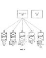
図1は、空気圧で動力が供給される眼科外科機械についての外科コンソール101の一つの実施形態を示す。外科コンソール101は、水晶体超音波乳化吸引術及び硝子体茎切除術のような様々な眼科外科処置の実行において外科医を補助すべく作動することができる。外科コンソール101は、内部監視システム、一つ以上のコントローラ(例えば比例制御機)、及び(水晶体超音波乳化吸引術用工具及び/又は空気圧工具103を含みうる)工具を含むことができる。空気圧工具103は、例えば剪刀、硝子体切除装置、鉗子、及び注入モジュール又は摘出モジュールを含むことができる。他の工具103が使用されてもよい。窒素のような圧縮ガスは、空気圧工具103に動力を提供することができる。圧縮ガスは、一つ以上の比例制御機への一つ以上のマニホールドと、工具103への追加のマニホールド及び/又は管とを通して、ガス圧力監視システムを通過することができる。
FIG. 1 illustrates one embodiment of a
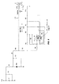
図2は、一つの実施形態に係る、空気圧で動力が供給される硝子体茎切除術用機械についての空気圧システムの概略図である。図2では、空気圧システムは、ポンプベントバルブ205と、出力バルブ210と、マフラー225、230、251、253と、マニホールド235と、空気圧工具103に動力を供給するためのそれぞれの空気圧チャネルについての出力ポートA及びBとを含むことができる(例えば図4参照)。
FIG. 2 is a schematic diagram of a pneumatic system for a vitrectomy machine powered by air pressure, according to one embodiment. In FIG. 2, the pneumatic system has an output for each of the pneumatic channels for powering the
いくつかの実施形態では、ポンプベントバルブ205は四方バルブである。バルブ205は、少なくとも二つの位置のうちの一方の位置にバルブを動かすように作動するソレノイドを含むことができる。一方の位置では、加圧ガスがポンプベントバルブ205を通過してマフラー230から出ることができる。別の位置では、ポンプベントバルブ205によって、加圧ガスが、工具103に動力を提供すべくポンプベントバルブ205を通過することができるようになる。ポンプベントバルブ205はコントローラ(例えば図3において見られるようなコントローラ300)によって制御されうる。
In some embodiments, the
いくつかの実施形態では、出力バルブ210は四方バルブである。バルブ210は、少なくとも二つの位置のうちの一方の位置にバルブを動かすように作動するソレノイドを含むことができる。一方の位置では、バルブ210は出力ポートAに加圧ガスを提供して出力ポートBから加圧ガスを排気することができる(すなわち「閉」位置)。この位置では、加圧ガスは出力ポートAに向かって出力バルブ210を通過して出力ポートAにおいて空気圧の動力を工具103に提供することができる。加圧ガスは出力バルブ210及びマフラー225を通過してマフラーにおいて大気に排出されることもできる。別の位置(すなわち「開」位置)では、出力バルブ210は、加圧ガスが出力ポートBに向かってバルブ265を通過して出力ポートBにおいて空気圧の動力を工具103に提供することを可能とする。加圧ガスはマフラー225に向かって出力バルブ210を通過してマフラー225において大気に排出されることもできる。出力バルブ210はコントローラ300によって制御されてもよい。いくつかの実施形態では、コントローラ300は、閉位置において閉じるようにソレノイドバルブに信号を送り(ソレノイドは、空気を逸らしてポートAを通すべくバルブを動かすように作用しうる)、信号が中断されると(又は開信号が送られると)バネ(又は他の作動機構)がバルブを開位置に戻すことができる(開位置ではバルブは、空気をポートBに逸らすように位置する)。50%のバルブデューティサイクルにおいて、コントローラは、信号が中断され(開位置)又は開信号が適用される時間とほぼ同じ量の時間の間、閉信号を適用しうる。
In some embodiments, the output valve 210 is a four-way valve. The valve 210 can include a solenoid that operates to move the valve to one of at least two positions. In one position, valve 210 can provide pressurized gas to output port A and exhaust the pressurized gas from output port B (ie, a “closed” position). In this position, the pressurized gas can pass through the output valve 210 toward the output port A to provide pneumatic power to the
いくつかの実施形態ではマニホールド組立体235はアルミニウムのような金属又はプラスチックから機械加工されうる。他の材料も考えられる。マニホールド組立体235は、気密であり、様々な接続具及び連結具を含み、且つ比較的高いガス圧に耐えるように設計されうる。マニホールド組立体235は個々の部材を収集して製造され又は単一部材として製造されうる。例えば、マニホールド組立体235はアルミニウムの単一部材から機械加工されてもよい。マフラー225、230、251、及び253は、漏洩ガス(escaping gas)によって作られる騒音を抑制することができる。
In some embodiments, the manifold assembly 235 can be machined from a metal such as aluminum or plastic. Other materials are also conceivable. Manifold assembly 235 is airtight, includes various connectors and couplers, and can be designed to withstand relatively high gas pressures. The manifold assembly 235 may be manufactured by collecting individual members or manufactured as a single member. For example, the manifold assembly 235 may be machined from a single piece of aluminum. The
図3は、一つの実施形態に係る、空気圧で動力が供給される硝子体茎切除術用機械についてのコントローラ300並びにバルブ205、210、261、263、及び265の概略図を示す。いくつかの実施形態では、コントローラ300は、バルブをコントローラに連結するインターフェースを介して、バルブ205、210、261、263、及び265に制御信号を送ることができる。インターフェースは、電線、バス、配線(trace)等のような導電体を含むことができる。コントローラ300は、ロジック機能を実行することができる集積回路でありうる。コントローラ300は、電源、入力ピン、及び出力ピンを備えた集積回路パッケージを含むことができる。様々な実施形態では、コントローラ300はバルブ又はターゲット装置のコントローラである。斯かる場合、コントローラ300は、バルブのような特定の装置に対するターゲットとされる特定の制御機能を実行することができる。いくつかの実施形態では、コントローラ300はマイクロプロセッサである。コントローラ300は、バルブ及び機械の他の構成要素を制御すべく機能することができるようにプログラム制御されうる。いくつかの実施形態では、コントローラ300は、種々の機能を実行する種々のバルブを制御するように構成された特定の目的のコントローラである。
FIG. 3 shows a schematic diagram of the
図4は(硝子体切除装置のような)工具103の一つの実施形態を示し、工具103は、切断装置として作用すべく出力ポートA及びBに取り付けられうる。カッター403がシリンダーによって動かされ、次いでシリンダーは加圧ガスによって動かされる。シリンダーは、加圧ガスが出力ポートA及びBに交互に向けられると上下動することができる。斯かる硝子体茎切除術用装置は、様々な切断率(例えば1分間当たり1000切断、1分間当たり2500切断、1分間当たり5000切断等)において作動するように設計されうる。他の切断率も考えられる。ポートA及びポートBは、工具103を駆動するために別個の空気圧チャネル(及び二つのチャネル間の差圧)を提供することができる。交流の圧力パルスが、二つのチャネル間の圧力出力を循環させる四方ソレノイドバルブ(例えば硝子体茎切除術用カッター制御バルブ210)によって発生せしめられることができる。図4において見られるように、圧力差は、結合されたプローブカッター403を工具103上で動かすべく工具103(例えばプローブ)の内側にダイアフラム401を相互に(reciprocally)動かすことができる。(例えばバルブの開位置又は閉位置においてより高い圧力差をもたらす)二つの空気圧チャネルにおける圧力バイアスが工具103の機能及び/又は特性に影響しうる。様々な要因(例えばバルブ毎の変動及び二つのチャネルにおける流れ制限/流れ抵抗のコンソール毎の変動)のせいで圧力差は種々のコンソール101における種々のバルブ210間で異なることがあり、このことは、不変の作動圧力差を提供する困難性をもたらす。二つの空気圧チャネルの出力の圧力差を制御すべく、ソフトウェアが、ソレノイドバルブ210の(バルブデューティサイクルとしても知られている)開/閉タイミングを制御するのに使用されうる。バルブデューティサイクルは、バルブの開/閉位置の両方における差圧のバランスをとるべく較正を通して調整されることができる。バルブデューティサイクルを調整することによって、より滑らかな工具の作動のためにバルブサイクルを通じてより不変の圧力差を実現すべく、バルブの開/閉サイクルにおける各空気圧チャネルに加圧ガスを供給するための時間が長くされ又は短くされうる。
FIG. 4 shows one embodiment of a tool 103 (such as a vitrectomy device) that can be attached to output ports A and B to act as a cutting device. The cutter 403 is moved by the cylinder, and then the cylinder is moved by the pressurized gas. The cylinder can move up and down as the pressurized gas is directed alternately to output ports A and B. Such a vitrectomy device can be designed to operate at various cutting rates (eg, 1000 cuts per minute, 2500 cuts per minute, 5000 cuts per minute, etc.). Other cutting rates are also possible. Port A and Port B can provide separate pneumatic channels (and differential pressure between the two channels) for driving the
例えば1分間当たり2500切断のプローブ率において、バルブ210は1サイクル当たり約24msの率においてポートA及びポートBに交互に加圧空気を提供することができる。1分間当たり2500切断の切断率を得るべく、二つの空気圧チャネルは24ms(2500切断/分又は1分/2500切断×60秒/1分=0.024秒/切断=24ms/切断)毎にオン/オフを循環させることができ、このことによって各チャネルは12ms開かれうる。いくつかの実施形態では、チャネルを実際に開閉するための移行時間がサイクル時間の一部を使用しうる。例えば、空気圧チャネル1(すなわち制御バルブ210のポートAを介する)は、24msのサイクルにつき6msの全移行時間について、開く(一方、空気圧チャネル2は閉じている)のに4msかかり且つ閉じる(一方、空気圧チャネル2は開いている)のに2msかかる。他の移行時間も考えられる。移行時間のせいで、実際にバルブは、チャネル2に対して閉じられている間にチャネル1に対して8ms(12ms−4ms)開かれることができ、且つチャネル2に対して開いている間にチャネル1に対して10ms(12ms−2ms)閉じられることができる。チャネル1及びチャネル2に加圧空気を提供する際の8ms対10msのバルブのこのタイミング差は二つのチャネルにおいてアンバランスな圧力差をもたらしうる。いくつかの実施形態では、二つのチャネルの開時間の持続時間がほぼ同じである(例えば2500切断/分の場合、約(24ms−6ms)/2=9ms実際に開かれる)ことが望ましい。移行タイミングが全てのバルブ210について一定である場合、その後ソフトウェア制御は、両チャネルについてほぼ等しい実際の開時間の持続時間を実現すべくバルブデューティサイクルを調整することができる。この例では、ソフトウェアは公称開時間(nominal open time)をチャネル1について13msに調整し且つチャネル2について11msに調整することができる。このため、この例について、移行時間を除くと、チャネル1の実際の開時間は13ms−4ms=9msであり、チャネル2の実際の開時間は(チャネル1と同様に)11ms−2ms=9msである。しかしながら、移行時間が様々なバルブ210の間で(例えばバルブ210における製造ばらつきのせいで)変化しうるので、固定されたタイミングオフセットは不均衡をうまく無効にすることができない。例えば、別のバルブは、チャネル1を開く(一方、空気圧チャネル2は閉じている)のに(4msの代わりに)3msかかり、且つチャネル1を閉じる(一方、空気圧チャネル2は開いている)のに2msかかる。同じソフトウェア制御のバルブデューティサイクル(例えばチャネル1について13msの公称開時間およびチャネル2について11msの公称開時間)を適用すると、空気圧チャネル1についての実際の開時間は13ms−3ms=10msであり、チャネル2についての実際の開時間は11ms−2ms=9msである。このため、この例では、空気圧チャネル1は実際に空気圧チャネル2よりも1ms又は11%長く開いたままである。この差は二つの空気圧チャネル間に不均衡な出力バランスをもたらすことがあり、このことは、より低い有効切断率/有効出力をもたらすことがある。同様に、固定されたタイミングオフセットは、二つのチャネルにおける流れ制限/流れ抵抗のコンソール毎の変動によって引き起こされる不均衡をうまく無効にすることができない。
For example, at a probe rate of 2500 cuts per minute, valve 210 can alternately provide pressurized air to port A and port B at a rate of about 24 ms per cycle. Two pneumatic channels are turned on every 24ms (2500 cuts / min or 1 minute / 2500 cuts x 60 seconds / 1 minute = 0.024 seconds / cut = 24ms / cut) to get a cut rate of 2500 cuts per minute / Off can be cycled so that each channel can be opened for 12 ms. In some embodiments, the transition time to actually open and close the channel may use a portion of the cycle time. For example, pneumatic channel 1 (ie, via port A of control valve 210) takes 4ms to open (while
いくつかの実施形態では、バルブデューティサイクルは(例えば様々なバルブの種々の移行時間及び様々なコンソールの流れ制限/流れ抵抗の変動を補償すべく)個々のバルブ及び/又はコンソールベースについて調整されうる。調整されたバルブデューティサイクルを空気圧チャネルについてのサイクル時間に適用することによって、空気圧チャネルは、全サイクル時間の間、ほぼ等しい実際の開時間を有するように作動されうる。上記されたように、50%のバルブデューティサイクルは、信号が適用されない(開位置に対応する)時間とほぼ同じ量の時間の間、バルブを閉じるように信号を適用することに対応する。1%の調整は51%のバルブデューティサイクルをもたらすことができ、51%のバルブデューティサイクルは、全サイクル時間の約51%の間バルブを閉じるように信号を適用する(且つ全時間の49%の間バルブを開くように、信号が適用されない(又は開信号が適用される))ことに対応する。このため、より長い51%のバルブデューティサイクルは、例えば、開くことよりも閉じるのにより長い時間がかかるバルブ、及び/又はバルブの閉位置に接続するチャネルにおいてより高い流れ制限/流れ抵抗を有するコンソールを補償することができる。 In some embodiments, the valve duty cycle may be adjusted for individual valves and / or console bases (eg, to compensate for various valve transition times and various console flow limit / flow resistance variations). . By applying the adjusted valve duty cycle to the cycle time for the pneumatic channel, the pneumatic channel can be operated to have an actual opening time that is approximately equal during the entire cycle time. As noted above, a 50% valve duty cycle corresponds to applying the signal to close the valve for approximately the same amount of time that the signal is not applied (corresponding to the open position). A 1% adjustment can result in a 51% valve duty cycle that applies a signal to close the valve for about 51% of the total cycle time (and 49% of the total time). Corresponds to no signal applied (or open signal applied) to open the valve during Thus, a longer 51% valve duty cycle, for example, a valve that takes longer to close than it opens and / or a console with higher flow restriction / flow resistance in the channel connected to the closed position of the valve. Can be compensated.
いくつかの実施形態では、バルブ210についてのバルブデューティサイクル値はコンソール101又は工具103上のメモリ303において記憶されうる。メモリ303は、ディップスイッチ(デュアル・インライン・パッケージスイッチ)、可変抵抗、デジタルポテンショメータ、又はEEPROM(電気的に消去可能なプログラマブル読み出し専用メモリ)を含むことができる。いくつかの実施形態では、バルブデューティサイクルは試行錯誤を通して決定され且つ(例えば製造において)メモリ303内にプログラムされ若しくは書き込まれ又は(例えばコンソール101のグラフィカル・ユーザー・インターフェース107内に入力される値のような)例えばコンソール101と使用者とのインタラクションを通して受信されうる。その後、バルブデューティサイクルは、バルブ210の開/閉時間を制御すべく外科コンソール101(例えば外科コンソール101内のコントローラ300)によって使用される。
In some embodiments, the valve duty cycle value for valve 210 may be stored in
図5a〜図6において見られるように、一つ以上のディップスイッチS1、S2、S3等が抵抗器のネットワークに接続されうる(抵抗器のネットワークの各々は、別の抵抗器を有することができる)。図5a及び図5cは5個のディップスイッチを備えた実施形態を示し、図5b及び図6は6個のディップスイッチを備えた実施形態を示す。図5dはn個のディップスイッチを備えた実施形態を示す。各ディップスイッチは、その対応する抵抗器を電流が通ることを可能とし又はその対応する抵抗器から電流を遮るべく1又は0(スイッチオン又はスイッチオフ)でプログラムされうる。抵抗器のネットワーク及びディップスイッチは、ディップスイッチの設定に基づく全ての抵抗を有することができる。例えば、(各々対応する抵抗器を備えた)6個のディップスイッチを用いて、抵抗器のネットワークは、26=64の可能な抵抗から選択された抵抗を有するように構成されうる。したがって、ディップスイッチの設定の組合せによって抵抗器ネットワークの種々の抵抗値を生成することができる。例えば、抵抗の倍数(resistance multiple)(例えばキロオーム)の例が図5a〜図6において各抵抗器の上に位置する(他の抵抗も可能である)。図5aにおいて見られるように、ネットワーク抵抗の例は、5つのディップスイッチの設定に基づいて1、2、3、4、5、6、7、8、9,10、11、12、13、14、15、16、17、18、19又は20である(示される形態では、32個のディップスイッチの組合せが、12個の重複に加えて1の増分の20個のネットワーク抵抗値を生成することができる)。他の形態(例えば別の抵抗値、別のディップスイッチ配置等)も可能である。図5bにおいて示された実施形態では、64個のディップスイッチの組合せが、24個の重複に加えて0.5の増分の40個のネットワーク抵抗値を生成することができる(例えば1、1.5、2、2.5、3、3.5、4、4.5、5、5.5、6、6.5、7、7.5、8、8.5、9、9.5、10、10.5、11、11.5、12、12.5、13、13.5、14、14.5、15、15.5、16、16.5、17、17.5、18、18.5、19、19.5、20、及び20.5のネットワーク抵抗値)。図5cにおいて見られるように、5個のディップスイッチの抵抗器ネットワークが、重複がない1の増分の32個のネットワーク抵抗値を生成すべく32個のディップスイッチの組合せを含むことができる(例えば1、2、3、4、5、6、7、8、9、10、11、12、13、14、15、16、17、18、19、20、21、22、23、24、25、26、27、28、29、30、31及び32の抵抗値)。図5dにおいて見られるように、n個のディップスイッチの抵抗器ネットワークが、重複がないRの増分の2n個のネットワーク抵抗値を生成すべく2n個のディップスイッチの組合せを含むことができる(例えば抵抗値はR、2R、3R、4R、5R、・・・、2nRである)。公知の電圧(例えば5ボルト)が抵抗器ネットワークに(例えば電圧源501によって)印加されることができ、結果として生じる電圧がアナログ/デジタル変換器509によってデジタルカウント511に変換されうる。外科コンソール上で実行するソフトウェアは、対応するバルブデューティサイクルを決定するのにデジタルカウント511を使用することができる。例えば、対応するバルブデューティサイクルの値を決定すべくテーブル参照がデジタルカウント上において実行されうる。いくつかの実施形態では、較正テーブル901(例えば図9参照)がデジタルカウント及び対応するバルブデューティサイクル値を備えてコンソールにおいて記憶されうる。
As seen in FIGS. 5a-6, one or more dip switches S1, S2, S3, etc. can be connected to a network of resistors (each of the network of resistors can have a separate resistor). ). 5a and 5c show an embodiment with five dip switches, and FIGS. 5b and 6 show an embodiment with six dip switches. FIG. 5d shows an embodiment with n dip switches. Each dip switch can be programmed with 1 or 0 (switch on or switch off) to allow current to flow through its corresponding resistor or to block current from its corresponding resistor. The resistor network and the dip switch can have all the resistances based on the setting of the dip switch. For example, using six dip switches (each with a corresponding resistor), the resistor network can be configured to have a resistance selected from 2 6 = 64 possible resistances. Therefore, various resistance values of the resistor network can be generated by combinations of DIP switch settings. For example, an example of resistance multiple (eg, kilo ohms) is located on each resistor in FIGS. 5a-6 (other resistances are possible). As seen in FIG. 5a, examples of network resistors are 1, 2, 3, 4, 5, 6, 7, 8, 9, 10, 11, 12, 13, 14 based on the settings of the five dip switches. , 15, 16, 17, 18, 19 or 20 (in the form shown, the combination of 32 dip switches produces 20 network resistance values in 1 increment in addition to 12 overlaps) Can do). Other forms (eg, different resistance values, different dip switch arrangements, etc.) are possible. In the embodiment shown in FIG. 5b, a combination of 64 dip switches can generate 40 network resistance values in increments of 0.5 in addition to 24 overlaps (
上記されたように、(例えば一組のディップスイッチ503における)ディップスイッチは、抵抗器のネットワーク505において選択された抵抗を組み合わせるべく様々なオン/オフ(1/0)位置においてプログラムされうる。抵抗器のネットワークは、ネットワークに印加された第1電圧の結果として第2電圧を出力すべく電圧分割器として作用することができる。ADC509は第2電圧をデジタルカウント511に変換することができる。例えば、電圧2は、(2.183ボルトの電圧に対応する)447のデジタルカウントをもたらす。外科コンソール上で実行するソフトウェアは、対応するバルブデューティサイクル(この場合49.5%)を決定すべく447のデジタルカウントを使用することができる。例えば、図9において見られるように、参照テーブルが、デジタルカウントに対応するバルブデューティサイクルを決定すべくアクセスされうる。いくつかの実施形態では、バルブデューティサイクルは決定されて書き込み可能なメモリ(例えばEEPROM)において記憶されうる。その後の外科コンソールの使用の間、ディップスイッチの使用を通してバルブデューティサイクルを決定する代わりにEEPROMが読み込まれうる。その後の使用についてEEPROMを使用することはバルブデューティサイクルのより迅速な決定を可能とする。EEPROMを使用することは、ディップスイッチが、うっかり切り換えられ、ぶつけられ、又は権限のない人員によって設定されることに関連する偽値を防ぐこともできる。いくつかの実施形態では、外科コンソールが、新しい値が決定されているという指示を受信すると、新しい値のデューティサイクルがEEPROM内に読み込まれうる(例えば、使用者は、使用者認証すべくユーザー・インターフェースにおいてパスワードを入力して新しいバルブデューティサイクルを受信するためにコンソールを設定し、又はスイッチを設定し若しくは(例えばディップスイッチから決定されるような)新しい値のデューティサイクルを検出してEEPROM内に記憶するように外科コンソールに指示するディップスイッチの近くのボタンを押すことができる)。
As described above, dip switches (eg, in a set of dip switches 503) can be programmed in various on / off (1/0) positions to combine selected resistors in
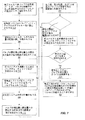
図7は、バルブ210を較正するためにバルブデューティサイクルを決定するための方法を示す。フローチャートにおいて提供される要素は単に説明のために存在する。提供される様々な要素を省略することができ、追加要素を追加することができ、且つ/又は以下に提供される順序とは異なる順序において様々な要素を実行することができる。 FIG. 7 illustrates a method for determining a valve duty cycle to calibrate the valve 210. The elements provided in the flowchart are for illustration only. The various elements provided can be omitted, additional elements can be added, and / or the various elements can be performed in a different order than the order provided below.
701において、較正されるべきバルブ210の空気圧ポートが、バルブ210の作動中の各ポートの圧力(又はポート間の差圧)を測定するために一つ以上の圧力センサに連結されうる。例えば、別個の圧力センサが各ポート(A及びB)に連結されることができ又は差圧センサがポートA及びポートBの両方に連結されてもよい。各ポートにおいて別個の圧力センサを使用する場合、差圧は、各ポートからの圧力データを使用して計算されうる。図1において見られるように、工具103は、ポート105を介してポートA及び/又はポートBに連結している一つ以上の圧力センサを備えた圧力トランスデューサボックスであってもよい。いくつかの実施形態では、バルブ210は、外科コンソールに連結された状態で試験されうる(例えば圧力センサは外科コンソール101の出力空気圧ポート105に連結されうる)。いくつかの実施形態では、1分間当たりの切断の設定(例えば1分間当たり2500切断)はバルブについて設定されうる。
At 701, the pneumatic port of valve 210 to be calibrated can be coupled to one or more pressure sensors to measure the pressure (or differential pressure between the ports) of each port during operation of valve 210. For example, a separate pressure sensor can be connected to each port (A and B) or a differential pressure sensor can be connected to both port A and port B. If a separate pressure sensor is used at each port, the differential pressure can be calculated using pressure data from each port. As can be seen in FIG. 1, the
703において、空気圧システムのバルブデューティサイクルがデフォルト値に設定されうる(例えば較正用ディップスイッチが50%のバルブデューティサイクルに設定され、このことによってバルブの開/閉タイミングにオフセットが適用されない)。ディップスイッチの設定は、較正テーブル901を使用して設定されることができ、較正テーブル901はバルブデューティサイクルに対するディップスイッチの設定に関する。 At 703, the valve duty cycle of the pneumatic system may be set to a default value (eg, the calibration dip switch is set to a 50% valve duty cycle, so that no offset is applied to the valve open / close timing). The setting of the dip switch can be set using the calibration table 901, which relates to the setting of the dip switch for the valve duty cycle.
705において、(バルブ210を含む)空気圧システムは、与えられた量の時間(例えば10秒)の間、作動されうる。空気圧システムの作動の間、運転についての圧力データが圧力センサを通して検出されうる。いくつかの実施形態では、フットスイッチペダルが、空気圧システムを始動すべく押し下げられてもよい。いくつかの実施形態では、空気圧システムは、特に空気圧システム及び/又はコンソールが新しい場合、長時間(例えば1〜2時間)の間作動されうる。較正前の長期の作動によって、システム及び/又はコンソールが、製造、摩擦点、及び他の構成要素の相互作用点(interaction point)によるバルブの初期変動を解決できるようになる(例えば、新しい部品が長期間他の部品と相互作用するので、新しい部品における初期摩擦がすり減らされうる)。いくつかの実施形態では、空気圧システムが、初期運転後に中断されて、その後、圧力データを採る前に別の設定量の時間(例えば5〜10秒)の間再び作動されてもよい。いくつかの実施形態では、待ち時間(例えば5〜10秒)が空気圧システムの運転の間に適用されてもよい。 At 705, the pneumatic system (including valve 210) can be activated for a given amount of time (eg, 10 seconds). During operation of the pneumatic system, pressure data about the operation can be detected through a pressure sensor. In some embodiments, the footswitch pedal may be depressed to start the pneumatic system. In some embodiments, the pneumatic system can be operated for extended periods of time (eg, 1-2 hours), particularly when the pneumatic system and / or console is new. Long-term operation prior to calibration allows the system and / or console to resolve initial valve variability due to manufacturing, friction points, and other component interaction points (eg, new parts Because it interacts with other parts for a long time, the initial friction in the new part can be worn down). In some embodiments, the pneumatic system may be interrupted after initial operation and then reactivated for another set amount of time (eg, 5-10 seconds) before taking pressure data. In some embodiments, a waiting time (eg, 5-10 seconds) may be applied during operation of the pneumatic system.
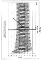
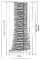
707において、バルブの開位置と閉位置との間の圧力差及び圧力範囲が決定されうる。図8aは、空気圧システムについて、時間に対する可能な圧力差のプロットを示す。図8aにおいて示されるように、サイクルインターバル時間(cycle interval time)(T)において圧力差は開位置において+68950Pa((+10psi(ポンド毎平方インチ))であり且つ閉位置において−89640Pa(−13psi)でありうる(このことは約158600Pa(23psi)の圧力範囲801をもたらす)。最低特性点は、開圧力と閉圧力との間の差圧の差が最小であるとき(すなわち(abs(開圧力)+abs(閉圧力))が圧力データについて最小であるとき)のサイクルインターバル時間でありうる。図8aにおいて示される場合、サイクルインターバル時間(T)において開位置についての圧力及び閉位置についての圧力の顕著な下落がある。
At 707, the pressure differential and pressure range between the open and closed positions of the valve can be determined. FIG. 8a shows a plot of possible pressure differences versus time for a pneumatic system. As shown in FIG. 8a, at the cycle interval time (T), the pressure differential is +68950 Pa ((+10 psi (pound per square inch)) in the open position and −89640 Pa (−13 psi) in the closed position. (This results in a
709において、圧力バイアスを補償するためのバルブデューティサイクルが決定されうる。図8aにおいて示される圧力データでは、サイクルインターバル時間(T)において、圧力バイアスは(+68950Pa(+10psi)の数値よりも上の−89640Pa(−13psi)の数値に関連付けられる)約20690Pa(3psi)であるように見える。(例えばサイクルインターバル時間(T)において約+79300Pa(+11.5psi)の開圧力値及び−79300Pa(−11.5psi)の閉圧力値を得ることを目的として)圧力差をほぼ中心にすることをもたらしうるバルブデューティサイクルが決定されうる。空気圧システムの最低特性点において圧力差を中心にすべくバルブデューティサイクルを決定することは、空気圧システムが、その最低特性点において開位置及び閉位置の両方において作動するのに十分な圧力を有することを保証することができる(バルブデューティサイクルは空気圧システムの他の作動点における改善された特性ももたらすことができる)。本明細書のいくつかの例では最低特性点付近においてバルブデューティサイクルが決定されるが、バルブデューティサイクルは、圧力データにおける他の点を使用して決定されてもよい。バルブデューティサイクルの決定は以下のように計算されうる。 At 709, a valve duty cycle to compensate for the pressure bias can be determined. In the pressure data shown in FIG. 8a, at the cycle interval time (T), the pressure bias is about 20690 Pa (3 psi) (associated with a value of −89640 Pa (−13 psi) above the value of +68950 Pa (+10 psi)). looks like. (For example, to obtain an open pressure value of about +79300 Pa (+11.5 psi) and a closed pressure value of −79300 Pa (−11.5 psi) at cycle interval time (T)), resulting in approximately centering the pressure difference. A possible valve duty cycle may be determined. Determining the valve duty cycle to center the pressure differential at the lowest characteristic point of the pneumatic system means that the pneumatic system has sufficient pressure to operate in both the open and closed positions at that lowest characteristic point (Valve duty cycle can also provide improved characteristics at other operating points of the pneumatic system). Although some examples herein determine the valve duty cycle near the lowest characteristic point, the valve duty cycle may be determined using other points in the pressure data. The determination of the valve duty cycle can be calculated as follows.
新しいバルブデューティサイクル=前のバルブデューティサイクル+(((abs(開圧力)−abs(閉圧力))/2)×(バルブデューティサイクルΔ/差圧変化Δ)) New valve duty cycle = previous valve duty cycle + (((abs (open pressure) −abs (close pressure)) / 2) × (valve duty cycle Δ / differential pressure change Δ))
ここで、開圧力及び閉圧力は空気圧システムについて最低特性の時間(例えば今回の例における時間T)において採られ、ここで、abs()は絶対値を表す。いくつかの実施形態では、圧力差の調整率に対するバルブデューティサイクルは数学的に又は試行錯誤を通して決定されうる。例えば、比率は5930Pa(0.86psi)(差圧変化Δ)に対して1%(バルブデューティサイクルΔ)である。 Here, the opening pressure and the closing pressure are taken at the time of the lowest characteristic for the pneumatic system (for example, time T in this example), where abs () represents an absolute value. In some embodiments, the valve duty cycle for the pressure differential adjustment rate may be determined mathematically or through trial and error. For example, the ratio is 1% (valve duty cycle Δ) for 5930 Pa (0.86 psi) (differential pressure change Δ).
今回の例では:
新しいバルブデューティサイクル=50%+(((89640Pa(13psi)−68950Pa(10psi))/2×(1%/5930Pa(0.86psi)))
新しいバルブデューティサイクル=50%+(10340Pa(1.5psi)×(1%/5930Pa(0.86psi)))
新しいバルブデューティサイクル=50%+1.744%=51.744%
In this example:
New valve duty cycle = 50% + (((89640 Pa (13 psi) −68950 Pa (10 psi)) / 2 × (1% / 5930 Pa (0.86 psi)))
New valve duty cycle = 50% + (10340 Pa (1.5 psi) × (1% / 5930 Pa (0.86 psi)))
New valve duty cycle = 50% + 1.744% = 51.744%
このため、閉じた側における圧力(ここでは+68950Pa(+10psi))は、51.744%(68950Pa(10psi)+1.744%×(5930Pa(0.86psi)/1%)=79300Pa(11.5psi))の新しいバルブデューティサイクルを用いて79300Pa(11.5psi)に増加せしめられ、開いた側は−79300Pa(−11.5psi)(−89640Pa(−13psi)+1.744%×(5930Pa(0.86psi)/1%)=−79300Pa(−11.5psi))にシフトされうる。いくつかの実施形態では、バルブデューティサイクルは最も近い増分に丸められる(例えば、最も近い増分の0.5%に丸める場合、51.5%に丸められる)。 Thus, the pressure on the closed side (here +68950 Pa (+10 psi)) is 51.744% (68950 Pa (10 psi) + 1.744% × (5930 Pa (0.86 psi) / 1%)) = 79300 Pa (11.5 psi) ) Is increased to 79300 Pa (11.5 psi) with the open side at -79300 Pa (-11.5 psi) (-89640 Pa (-13 psi) + 1.744% x (5930 Pa (0.86 psi)) ) / 1%) = − 79300 Pa (−11.5 psi)). In some embodiments, the valve duty cycle is rounded to the nearest increment (eg, rounded to 51.5% if rounding to 0.5% of the nearest increment).
711において、空気圧システムが新しいバルブデューティサイクルを用いてプログラムされうる。例えば、(オン/オフ又は1/0の選択肢を備えた物理的にアクセス可能なスイッチであってもよい)ディップスイッチはオン/オフシーケンス(on/off sequence)において設定されることができ、オン/オフシーケンスは、決定されたバルブデューティサイクルに対応する電圧を生成するであろう。いくつかの実施形態では、新しいバルブデューティサイクルは外科コンソールによって算出され且つ/又は外科コンソールのグラフィカル・ユーザー・インターフェース内に入力されうる。 At 711, the pneumatic system can be programmed with a new valve duty cycle. For example, a dip switch (which may be a physically accessible switch with on / off or 1/0 choices) can be set in an on / off sequence and turned on The / off sequence will generate a voltage corresponding to the determined valve duty cycle. In some embodiments, the new valve duty cycle may be calculated by the surgical console and / or entered into the graphical user interface of the surgical console.
713において、空気圧システムが再び(例えば5〜10秒間)作動されうる。空気圧システムの作動の間、運転についての圧力データが圧力センサを通して検出されうる。いくつかの実施形態では、空気圧システムは、最初の運転後に中断されて、その後、圧力データを採る前に別の設定量の時間(例えば5〜10秒)の間再び運転する。いくつかの実施形態では、待ち時間(例えば5〜10秒)が空気圧システムの運転の間に適用されうる。 At 713, the pneumatic system can be activated again (eg, for 5-10 seconds). During operation of the pneumatic system, pressure data about the operation can be detected through a pressure sensor. In some embodiments, the pneumatic system is interrupted after the first run and then runs again for another set amount of time (eg, 5-10 seconds) before taking pressure data. In some embodiments, a waiting time (eg, 5-10 seconds) may be applied during operation of the pneumatic system.
715において、バルブの開位置と閉位置との間の圧力差及び圧力範囲が再び決定されうる。図8bは、新しいバルブデューティサイクルを適用した後の圧力データの可能なプロットを示す。図8bにおいて見られるように、圧力差は、閉位置における圧力差が閉位置についての最低特性点において約79300Pa(11.5psi)であり且つ開位置における最低特性点について約−79300Pa(−11.5psi)であるように、ほぼ0Pa(0psi)付近に中心が合わせられうる。 At 715, the pressure differential and pressure range between the open and closed positions of the valve can be determined again. FIG. 8b shows a possible plot of pressure data after applying a new valve duty cycle. As seen in FIG. 8b, the pressure difference is about 79300 Pa (11.5 psi) at the lowest characteristic point for the closed position and about −79300 Pa (−11. The center can be centered around 0 Pa (0 psi), such as 5 psi).
717において、圧力差、圧力範囲、及び/又は圧力バイアスが許容可能な制限値と比較されうる。いくつかの実施形態では、圧力差(例えば、修正された場合、圧力差は、図8bにおいて見られるように約+79300Pa(+11.5psi)及び約−79300Pa(−11.5psi)である)は、作動について予め定められた閾値と比較されうる(例えば圧力差の絶対値が約68950Pa(10psi)の閾値と比較される)。図8bにおいて示される修正された場合、差圧(比較目的のための絶対値)は68950Pa(10psi)の閾値よりも大きい。いくつかの実施形態では、圧力バイアス(二つのチャネル間の圧力差)が、決定されて、予め定められた許容可能な制限値と比較されてもよい。例えば、圧力バイアスはabs(閉圧力)−abs(開圧力)に等しい。較正後、6895Pa(1psi)の予め定められた許容可能な圧力バイアスの制限値が使用されてもよい(他の圧力バイアスが、空気圧システムの較正に応じて使用されてもよい)。別の例として、全圧力範囲(abs(開圧力)+abs(閉圧力))が、予め定められた許容可能な制限値(例えば最小148900Pa(21.6psi)の範囲)と比較される。いくつかの実施形態では、空気圧システムについての最低特性の点における全圧力範囲が、空気圧システムが漏れ又は制限を有するかどうか判定すべく許容可能な全圧力範囲と比較されてもよい。例えば、全圧力範囲が148900Pa(21.6psi)よりも小さい場合、システムにおいて漏れ又は制限がある場合がある。他の全圧力範囲が使用されてもよい(別の空気圧システムの形態が別の圧力及び圧力範囲において作動しうる)。最低特性点における全圧力範囲が最小の許容可能な制限値を満たさない場合、バルブが取り替えられ且つ/又は空気圧システムが検査されうる。また、圧力波の形態のエッジが、滑らかでないが波形であり、若しくはシフトを有し、又は最低特性点後の両側において大きくならない場合、バルブは、取り替えられる必要がある場合がある。 At 717, the pressure differential, pressure range, and / or pressure bias can be compared to an acceptable limit value. In some embodiments, the pressure differential (eg, when modified, the pressure differential is about +79300 Pa (+11.5 psi) and about −79300 Pa (−11.5 psi) as seen in FIG. 8b) is: It can be compared to a predetermined threshold for operation (eg, the absolute value of the pressure difference is compared to a threshold of about 68950 Pa (10 psi)). In the modified case shown in FIG. 8b, the differential pressure (absolute value for comparison purposes) is greater than a threshold of 68950 Pa (10 psi). In some embodiments, the pressure bias (pressure difference between the two channels) may be determined and compared to a predetermined acceptable limit value. For example, the pressure bias is equal to abs (closing pressure) -abs (opening pressure). After calibration, a predetermined allowable pressure bias limit of 6895 Pa (1 psi) may be used (other pressure biases may be used depending on the calibration of the pneumatic system). As another example, the full pressure range (abs (open pressure) + abs (close pressure)) is compared to a predetermined acceptable limit (eg, a range of 148900 Pa (21.6 psi) minimum). In some embodiments, the full pressure range at the point of lowest characteristic for the pneumatic system may be compared to an acceptable full pressure range to determine whether the pneumatic system has a leak or restriction. For example, if the total pressure range is less than 148900 Pa (21.6 psi), there may be leaks or limitations in the system. Other full pressure ranges may be used (other pneumatic system configurations may operate at different pressures and pressure ranges). If the entire pressure range at the lowest characteristic point does not meet the minimum acceptable limit value, the valve can be replaced and / or the pneumatic system can be tested. Also, if an edge in the form of a pressure wave is not smooth but corrugated, or has a shift, or does not grow on both sides after the lowest characteristic point, the valve may need to be replaced.
719において、全圧力範囲又は圧力バイアスが許容可能な範囲から逸脱している場合、新しいバルブデューティサイクルが使用されうる。いくつかの実施形態では、新しいバルブデューティサイクルが再計算されうる。 If the full pressure range or pressure bias deviates from an acceptable range at 719, a new valve duty cycle can be used. In some embodiments, a new valve duty cycle can be recalculated.
例えば:
新しいバルブデューティサイクル=前のバルブデューティサイクル+(((abs(開圧力)−abs(閉圧力))/2)×(バルブデューティサイクルΔ/圧力変化Δ))
For example:
New valve duty cycle = previous valve duty cycle + (((abs (open pressure) −abs (close pressure)) / 2) × (valve duty cycle Δ / pressure change Δ))
ここでは、開圧力及び閉圧力は空気圧システムについての最低特性の時間における差圧でありうる。いくつかの実施形態では、方程式を使用する代わりに、前のバルブデューティサイクルよりも上又は下の増分1のバルブデューティサイクルが試されてもよい。(開位置の方に向かって圧力バイアスを減少させるべく)前の閉圧力が増加せしめられる必要がある場合、バルブデューティサイクルは次の増分(例えば51%から51.5%)に増加せしめられ又は逆も同様である。いくつかの実施形態では、新しいバルブデューティサイクルは外科コンソールによって決定され且つ/又は外科コンソールのグラフィカル・ユーザー・インターフェース内に入力されうる。いくつかの実施形態では、ディップスイッチは、決定された新しいバルブデューティサイクルに対応するように設定されうる。その後、新しいバルブデューティサイクルは(例えば要素713〜719を実行することによって)試験されうる。 Here, the opening pressure and the closing pressure can be the differential pressure in time of the lowest characteristic for the pneumatic system. In some embodiments, instead of using an equation, an incremental one valve duty cycle above or below the previous valve duty cycle may be tried. If the previous closing pressure needs to be increased (to reduce the pressure bias towards the open position), the valve duty cycle is increased to the next increment (eg 51% to 51.5%) or The reverse is also true. In some embodiments, the new valve duty cycle can be determined by the surgical console and / or entered into the graphical user interface of the surgical console. In some embodiments, the dip switch can be set to correspond to the determined new valve duty cycle. The new valve duty cycle can then be tested (eg, by performing elements 713-719).
721において、バルブが時間の設定数(例えば二回)よりも多く試験され且つ全圧力範囲又は圧力バイアスがそれでもなお許容可能な範囲から逸脱している場合、別のバルブ/モジュールが設置されうる。いくつかの実施形態では、新しいバルブデューティサイクルを決定する追加の回(round)が実行されてもよい(又はディップスイッチは前の値よりも上又は下の別のバルブデューティサイクルに対応するように動かされてもよい)。 At 721, if the valve has been tested more than a set number of times (eg, twice) and the full pressure range or pressure bias is still outside the acceptable range, another valve / module can be installed. In some embodiments, additional rounds of determining a new valve duty cycle may be performed (or the dip switch may correspond to another valve duty cycle above or below the previous value). May be moved).
723において、717からの全圧力範囲及び圧力バイアスが許容可能な範囲内にある場合、較正プロセスが完了されうる。外科コンソールは、決定されたバルブデューティサイクルを使用することができる。いくつかの実施形態では、ディップスイッチ及び抵抗器ネットワークが作動中に(特有の電圧を通して)所望のバルブデューティサイクルをシステムコンソールに中継することができる。例えば、抵抗器ネットワークからの電圧がアナログ/デジタル変換器509を通してデジタルカウントに変換される。デジタルカウントは、外科コンソール上で実行するソフトウェアによって処理されることができ、対応するバルブデューティサイクルが、決定されて、バルブ特性を修正するのに使用されうる。いくつかの実施形態では、較正プロセスは、決定されたバルブデューティサイクルを有する較正結果の再現性を保証すべく複数回実行されてもよい。 At 723, if the total pressure range from 717 and the pressure bias are within acceptable ranges, the calibration process can be completed. The surgical console can use the determined valve duty cycle. In some embodiments, the desired valve duty cycle can be relayed to the system console (through a unique voltage) while the dip switch and resistor network is operating. For example, the voltage from the resistor network is converted to a digital count through an analog / digital converter 509. The digital count can be processed by software running on the surgical console and the corresponding valve duty cycle can be determined and used to modify the valve characteristics. In some embodiments, the calibration process may be performed multiple times to ensure the reproducibility of calibration results having a determined valve duty cycle.
いくつかの実施形態では、硝子体茎切除術用システムは一つ以上のプロセッサ(例えばコントローラ300)を含んでもよい。コントローラ300は単一の処理装置又は複数の処理装置を含むことができる。斯かる処理装置は、マイクロプロセッサ、(マイクロコントローラでありうる)コントローラ、デジタル・シグナル・プロセッサ、マイクロコンピュータ、中央演算処理ユニット、フィールド・プログラマブル・ケート・アレイ、プログラマブル・ロジック・デバイス、ステートマシン、論理回路、制御回路、アナログ回路、デジタル回路、及び/又は操作指令に基づいて(アナログ及び/又はデジタル)信号を操作する任意の装置である。プロセッサに連結され且つ/又は組み込まれたメモリは単一のメモリ装置又は複数のメモリ装置である。斯かるメモリ装置は、ROM、RAM、揮発性メモリ、不揮発性メモリ、スタティックメモリ、ダイナミックメモリ、フラッシュメモリ、キャッシュメモリ、及び/又はデジタル情報を記憶する任意の装置である。プロセッサが、ステートマシン、アナログ回路、デジタル回路、及び/又はロジック回路を介してその一つ以上の機能を実施するとき、対応する操作指令を記憶するメモリが、ステートマシン、アナログ回路、デジタル回路、及び/又はロジック回路を含む回路内に又は回路の外部に組み込まれうることに留意されたい。例えば図7に関連して示され且つ記述された要素の少なくともいくつかに対応する操作指令を、メモリが記憶してプロセッサが実行することができる。
In some embodiments, the vitrectomy system may include one or more processors (eg, controller 300). The
与えられた実施形態に対して様々な修正が当業者によってなされうる。本明細書及び例が単なる模範例としてみなされ、本発明の真の範囲及び思想が以下の特許請求の範囲及びその均等物によって示されることが意図されている。 Various modifications can be made to the given embodiments by those skilled in the art. It is intended that the specification and examples be considered as exemplary only, with a true scope and spirit of the invention being indicated by the following claims and their equivalents.
Claims (16)
バルブと、
該バルブに連結された少なくとも第1及び第2のポートであって、前記バルブが、当該外科コンソールに連結された空気圧工具を駆動すべく該第1ポート及び第2ポートの各々に交互に加圧ガスを提供するように構成される、少なくとも第1及び第2のポートと、
前記第1及び第2のポートに連結された少なくとも一つの圧力センサと、
前記バルブに連結されたコントローラであって、前記バルブの開時間および閉時間を制御すべく作動可能であり、該バルブの開時間が前記第1ポートを開くための時間に対応し、該バルブの閉時間が前記第1ポートを閉じるための時間に対応し、前記第1ポートを閉じることが、加圧空気が前記バルブによって前記第1ポート又は第2ポートを通して向けられるように該第2ポートを開くことと一致する、コントローラと
を具備する、外科コンソールにおいて、
前記コントローラが、バルブデューティサイクルに従って前記バルブの開/閉時間を調整するように構成され、
前記バルブの開位置及び閉位置についての作動圧力データが分析され、前記バルブデューティサイクルが、予め定められた閾値を超えた開作動の差圧及び閉作動の差圧をもたらすバルブの開時間及び閉時間を提供するように調整され、
前記バルブデューティサイクルが、前記外科コンソールの試験中の圧力データを使用して決定され、且つ前のバルブデューティサイクル+(((abs(開圧力)−abs(閉圧力))/2)×(バルブデューティサイクルΔ/差圧変化Δ))にほぼ等しく、ここで、前記前のバルブデューティサイクルが試験中のバルブデューティサイクルであり、開圧力及び閉圧力が前記バルブの一つのサイクルについての前記ポートについての差圧であり、前記バルブデューティサイクルΔ/差圧変化Δが、結果として生じる差圧変化に対するバルブデューティサイクルの変化の比率である、外科コンソール。 A surgical console,
A valve,
At least first and second ports connected to the valve, wherein the valve alternately pressurizes each of the first and second ports to drive a pneumatic tool connected to the surgical console. At least first and second ports configured to provide gas;
At least one pressure sensor coupled to the first and second ports;
A controller coupled to the valve, the controller being operable to control an opening time and a closing time of the valve, wherein the opening time of the valve corresponds to a time for opening the first port; The closing time corresponds to the time for closing the first port, and closing the first port causes the second port to be directed so that pressurized air is directed through the first or second port by the valve. In a surgical console comprising a controller coincident with opening
The controller is configured to adjust the open / close time of the valve according to a valve duty cycle;
The operating pressure data for the open and closed positions of the valve is analyzed, and the valve duty cycle results in the valve opening time and closing resulting in an open differential pressure and a closed differential pressure exceeding a predetermined threshold. Adjusted to provide time ,
The valve duty cycle is determined using pressure data during testing of the surgical console and the previous valve duty cycle + (((abs (open pressure) -abs (closed pressure)) / 2) × (valve Duty cycle Δ / differential pressure change Δ)), where the previous valve duty cycle is the valve duty cycle under test, and the open and close pressures for the port for one cycle of the valve a differential pressure, the valve duty cycle delta / difference pressure change delta is Ru ratio der of change in the valve duty cycle for the difference pressure change resulting surgical console.
開位置と閉位置との間を循環するように構成された空気圧バルブを具備する空気圧システムを作動させるステップであって、加圧ガスが、前記バルブが前記開位置にあるときに第1ポートに向けられ且つ前記バルブが前記閉位置にあるときに第2ポートに向けられる、ステップと、
前記空気圧バルブによる圧力出力を測定するステップであって、該測定された圧力データが、前記開位置における前記第1ポートと前記第2ポートとの間の差圧に対応する開差圧と、前記閉位置における前記第1ポートと前記第2ポートとの間の差圧に対応する閉差圧とを含む、ステップと、
新しいバルブデューティサイクルを計算するステップであって、該新しいバルブデューティサイクルが前のバルブデューティサイクル+(((abs(開圧力)−abs(閉圧力))/2)×(バルブデューティサイクルΔ/圧力差変化Δ))にほぼ等しく、ここで、前記前のバルブデューティサイクルが、前記圧力を測定している間における前記空気圧システムの作動中の前記バルブデューティサイクルであり、開圧力と閉圧力とが、前記バルブの一つのサイクルの対応する開位置において前記ポートについて測定された差圧と、対応する閉位置において前記ポートについて測定された差圧とであり、前記バルブデューティサイクルΔ/差圧変化Δが、結果として生じる差圧変化に対するバルブデューティサイクルの変化の比率である、ステップと
を含む、方法。 In a method of calibrating a surgical pneumatic system,
Activating a pneumatic system comprising a pneumatic valve configured to circulate between an open position and a closed position, wherein pressurized gas is applied to the first port when the valve is in the open position; Directed and directed to a second port when the valve is in the closed position;
Measuring a pressure output by the pneumatic valve, wherein the measured pressure data includes an open differential pressure corresponding to a differential pressure between the first port and the second port at the open position; A closed differential pressure corresponding to a differential pressure between the first port and the second port in a closed position;
Calculating a new valve duty cycle, where the new valve duty cycle is the previous valve duty cycle + (((abs (open pressure) −abs (close pressure)) / 2) × (valve duty cycle Δ / pressure Approximately equal to the difference change Δ)), where the previous valve duty cycle is the valve duty cycle during operation of the pneumatic system while measuring the pressure, and the opening and closing pressures are A differential pressure measured for the port at a corresponding open position of one cycle of the valve and a differential pressure measured for the port at a corresponding closed position, wherein the valve duty cycle Δ / differential pressure change Δ Is the ratio of the change in valve duty cycle to the resulting change in differential pressure. Including a method.
全圧力範囲を計算するステップであって、該全圧力範囲が前記開圧力及び閉圧力の絶対値の合計にほぼ等しい、ステップと、
前記全圧力範囲が、予め定められた全圧力範囲の制限値よりも大きいかどうか判定するステップと
を更に含む、請求項12に記載の方法。 Activating the pneumatic system to measure the pressure output by the pneumatic valve;
Calculating a total pressure range, the total pressure range being approximately equal to the sum of the absolute values of the open and closed pressures;
13. The method of claim 12 , further comprising determining whether the total pressure range is greater than a predetermined total pressure range limit.
圧力バイアスを計算するステップであって、該圧力バイアスがabs(閉圧力)−abs(開圧力)にほぼ等しい、ステップと、
前記圧力バイアスが、予め定められた圧力バイアスの制限値よりも小さいどうか判定するステップと
を更に含む、請求項12に記載の方法。 Activating the pneumatic system to measure the pressure output by the pneumatic valve;
Calculating a pressure bias, the pressure bias being approximately equal to abs (closed pressure) -abs (open pressure);
The method of claim 12 , further comprising: determining whether the pressure bias is less than a predetermined pressure bias limit value.
Applications Claiming Priority (3)
| Application Number | Priority Date | Filing Date | Title |
|---|---|---|---|
| US23843109P | 2009-08-31 | 2009-08-31 | |
| US61/238,431 | 2009-08-31 | ||
| PCT/US2010/045136 WO2011025658A1 (en) | 2009-08-31 | 2010-08-11 | Pneumatic pressure output control by drive valve duty cycle calibration |
Publications (3)
| Publication Number | Publication Date |
|---|---|
| JP2013503024A JP2013503024A (en) | 2013-01-31 |
| JP2013503024A5 JP2013503024A5 (en) | 2013-09-19 |
| JP5770731B2 true JP5770731B2 (en) | 2015-08-26 |
Family
ID=43033172
Family Applications (1)
| Application Number | Title | Priority Date | Filing Date |
|---|---|---|---|
| JP2012527889A Active JP5770731B2 (en) | 2009-08-31 | 2010-08-11 | Control of pneumatic output by drive valve duty |
Country Status (8)
| Country | Link |
|---|---|
| US (2) | US8818564B2 (en) |
| EP (1) | EP2473144B1 (en) |
| JP (1) | JP5770731B2 (en) |
| CN (1) | CN102497841B (en) |
| AU (1) | AU2010286834B2 (en) |
| CA (1) | CA2770487C (en) |
| ES (1) | ES2551581T3 (en) |
| WO (1) | WO2011025658A1 (en) |
Families Citing this family (23)
| Publication number | Priority date | Publication date | Assignee | Title |
|---|---|---|---|---|
| WO2011025658A1 (en) | 2009-08-31 | 2011-03-03 | Alcon Research, Ltd. | Pneumatic pressure output control by drive valve duty cycle calibration |
| CN102652006B (en) | 2009-12-10 | 2014-06-11 | 爱尔康研究有限公司 | Systems and methods for dynamic pneumatic valve driver |
| US8821524B2 (en) * | 2010-05-27 | 2014-09-02 | Alcon Research, Ltd. | Feedback control of on/off pneumatic actuators |
| WO2012064864A1 (en) | 2010-11-09 | 2012-05-18 | Aegea Medical Inc. | Positioning method and apparatus for delivering vapor to the uterus |
| US8403917B2 (en) * | 2010-12-29 | 2013-03-26 | Bausch & Lomb Incorporated | Pneumatic surgical instrument detection system |
| US8808318B2 (en) | 2011-02-28 | 2014-08-19 | Alcon Research, Ltd. | Surgical probe with increased fluid flow |
| US9060841B2 (en) | 2011-08-31 | 2015-06-23 | Alcon Research, Ltd. | Enhanced flow vitrectomy probe |
| CA2851355C (en) | 2011-10-07 | 2020-02-18 | Aegea Medical Inc. | Integrity testing method and apparatus for delivering vapor to the uterus |
| NL2009424C2 (en) | 2012-09-06 | 2014-03-10 | D O R C Dutch Ophthalmic Res Ct International B V | Irrigation/aspiration system, cartridge, pump unit, surgical machine, method for controlling. |
| US9498376B2 (en) | 2012-12-17 | 2016-11-22 | Abbott Medical Optics Inc. | Vitrectomy surgical apparatus with cut timing based on pressures encountered |
| US9271867B2 (en) | 2012-12-17 | 2016-03-01 | Abbott Medical Optics Inc. | Vitrectomy surgical apparatus with regulating of material processed |
| US9486358B2 (en) | 2012-12-17 | 2016-11-08 | Abbott Medical Optics Inc. | Vitrectomy surgical apparatus |
| US9615969B2 (en) | 2012-12-18 | 2017-04-11 | Novartis Ag | Multi-port vitrectomy probe with dual cutting edges |
| CA2946723A1 (en) | 2014-04-23 | 2015-10-29 | Abbott Medical Optics Inc. | Vitrectomy surgical apparatus employing multisensor pressure feedback |
| ES2942296T3 (en) * | 2014-05-22 | 2023-05-31 | Aegea Medical Inc | Integrity test method and apparatus for administering vapor to the uterus |
| WO2015179666A1 (en) | 2014-05-22 | 2015-11-26 | Aegea Medical Inc. | Systems and methods for performing endometrial ablation |
| US9693898B2 (en) | 2014-11-19 | 2017-07-04 | Novartis Ag | Double-acting vitreous probe with contoured port |
| CA2979414C (en) * | 2015-04-13 | 2023-08-29 | Novartis Ag | High speed pneumatic valve |
| US11331037B2 (en) | 2016-02-19 | 2022-05-17 | Aegea Medical Inc. | Methods and apparatus for determining the integrity of a bodily cavity |
| CN106642557A (en) * | 2016-12-05 | 2017-05-10 | 广东美的制冷设备有限公司 | Water tank water discharge switch noise reduction control method and system and air conditioner |
| US11540942B2 (en) | 2018-07-26 | 2023-01-03 | Alcon Inc. | Redundant pneumatic circuit for reliability enhancement of vitrectomy instruments |
| US11642243B2 (en) * | 2018-12-10 | 2023-05-09 | Alcon Inc. | Methods of solenoid valve control optimization |
| CN115335013A (en) | 2020-01-03 | 2022-11-11 | 雷萨公司 | Compact reconfigurable integrated laser phacoemulsification system and method of use |
Family Cites Families (170)
| Publication number | Priority date | Publication date | Assignee | Title |
|---|---|---|---|---|
| US812162A (en) * | 1905-12-18 | 1906-02-06 | Thomas Bemis | Pneumatic tube for store service. |
| US2016746A (en) * | 1933-08-25 | 1935-10-08 | Thomas H Ireland | Fluid heater |
| NL73735C (en) * | 1949-06-30 | |||
| GB792397A (en) | 1956-05-09 | 1958-03-26 | Pneumatic Components Ltd | Improvements in or relating to tyre inflation hose equipment |
| US3084674A (en) * | 1961-07-20 | 1963-04-09 | Ingersoll Rand Co | Pneumatic system for multiple nut runner |
| US3601588A (en) | 1966-05-23 | 1971-08-24 | Foxboro Co | Method and apparatus for adaptive control |
| FR1506385A (en) | 1966-09-16 | 1967-12-22 | Sud Aviation | Method of attenuation and electro-hydraulic vibration attenuator for rotary wing aerodyne |
| US3515155A (en) | 1967-02-24 | 1970-06-02 | Air Reduction | Gas mixture proportioner |
| US3646727A (en) * | 1969-06-02 | 1972-03-07 | Erich A Wachsmuth | Automatic compressor drain system |
| GB1281196A (en) * | 1969-11-20 | 1972-07-12 | Westland Aircraft Ltd | Improvements in or relating to pressure control systems |
| FR2117726B1 (en) | 1970-12-10 | 1973-12-07 | Aquitaine Petrole | |
| US3815604A (en) * | 1972-06-19 | 1974-06-11 | Malley C O | Apparatus for intraocular surgery |
| US3867934A (en) * | 1973-05-04 | 1975-02-25 | Veriflo Corp | Pressure monitor for a lung ventilator |
| US3854382A (en) | 1973-06-20 | 1974-12-17 | Sperry Rand Ltd | Hydraulic actuator controls |
| GB1417299A (en) | 1973-09-18 | 1975-12-10 | Gulde Regelarmatuhren Kg | Method and apparatus for safe-guarding pipe-lines against inadmissibly high internal pressure by a control valve with a pneumatic drive |
| US4011869A (en) * | 1975-08-01 | 1977-03-15 | David Kopf Instruments | Tubular cutting instrument |
| GB1518720A (en) | 1975-11-21 | 1978-07-26 | Ishikawajima Harima Heavy Ind | Hydraulic servomechanism |
| US4077567A (en) * | 1976-06-18 | 1978-03-07 | Universal Pneumatic Controls, Inc. | Pneumatic temperature reset differential pressure controller |
| US4323064A (en) * | 1976-10-26 | 1982-04-06 | Puritan-Bennett Corporation | Volume ventilator |
| US4086804A (en) * | 1976-10-26 | 1978-05-02 | Sperry Rand Corporation | Precision pneumatic pressure supply system |
| US4168707A (en) * | 1977-06-13 | 1979-09-25 | Douvas Nicholas G | Control apparatus for microsurgical instruments |
| US4335867A (en) * | 1977-10-06 | 1982-06-22 | Bihlmaier John A | Pneumatic-hydraulic actuator system |
| US4368734A (en) * | 1978-01-27 | 1983-01-18 | Surgical Design Corp. | Surgical instrument |
| US4255789A (en) * | 1978-02-27 | 1981-03-10 | The Bendix Corporation | Microprocessor-based electronic engine control system |
| DE2811345C2 (en) * | 1978-03-16 | 1986-12-11 | Knorr-Bremse AG, 8000 München | Pressure regulators for pneumatic pressures, in particular in vehicles |
| JPS5584858A (en) * | 1978-12-18 | 1980-06-26 | Nippon Denso Co Ltd | Engine control |
| FR2455766B1 (en) * | 1979-05-02 | 1985-09-06 | Intertechnique Sa | PNEUMATIC DEVICE AND INSTALLATION FOR CREATING PRESSURE OR FLOW CYCLES |
| US4331130A (en) * | 1980-06-27 | 1982-05-25 | Lewicky Andrew O | Securing device to the cornea to prevent anterior chamber prolapse |
| US4590935A (en) * | 1981-11-02 | 1986-05-27 | Optikon Oftalmologia, S.P.A. | Control system for intraocular surgical device |
| GB2140871A (en) | 1983-06-03 | 1984-12-05 | Bowthorpe Hellermann Ltd | Piston and cylinder actuator control |
| US4679583A (en) * | 1984-04-19 | 1987-07-14 | Robertshaw Controls Company | Pneumatic control system, control means therefor and method of making the same |
| BR8403165A (en) * | 1984-06-28 | 1984-11-27 | Jaime Roizenblatt | PNEUMATIC MODULE FOR INTRAOCULAR MICROSURGERY |
| US4678459A (en) * | 1984-07-23 | 1987-07-07 | E-Z-Em, Inc. | Irrigating, cutting and aspirating system for percutaneous surgery |
| US4706687A (en) * | 1985-02-28 | 1987-11-17 | Alcon Instrumentation, Inc. | Linear suction control system |
| US4757814A (en) * | 1985-02-28 | 1988-07-19 | Alcon Laboratories, Inc. | Proportional control for pneumatic cutting device |
| US4650462A (en) * | 1985-07-29 | 1987-03-17 | Minnesota Mining And Manufacturing Company | Irrigation system |
| US4622503A (en) * | 1985-09-26 | 1986-11-11 | Medical Instrument Development Laboratories, Inc. | Variable pneumatic output means for use with ophthalmic micro-surgical instruments |
| US4790816A (en) * | 1985-09-26 | 1988-12-13 | Allon Laboratories, Inc. | Surgical cassette proximity sensing and latching apparatus |
| US4810242A (en) * | 1985-09-26 | 1989-03-07 | Alcon Laboratories Inc. | Surgical cassette proximity sensing and latching apparatus |
| US4770654A (en) * | 1985-09-26 | 1988-09-13 | Alcon Laboratories Inc. | Multimedia apparatus for driving powered surgical instruments |
| US4696298A (en) * | 1985-11-19 | 1987-09-29 | Storz Instrument Company | Vitrectomy cutting mechanism |
| US4840111A (en) * | 1986-01-31 | 1989-06-20 | Moog Inc. | Energy-conserving regenerative-flow valves for hydraulic servomotors |
| US4933843A (en) * | 1986-11-06 | 1990-06-12 | Storz Instrument Company | Control system for ophthalmic surgical instruments |
| EP0305382B1 (en) | 1987-03-18 | 1996-09-11 | Monroe Auto Equipment Company | Method and apparatus for absorbing mechanical shock |
| DE3708989C2 (en) | 1987-03-19 | 1993-10-14 | Festo Kg | Control device for a piston displaceable in a double-acting cylinder |
| US5239861A (en) * | 1988-12-23 | 1993-08-31 | Kabushiki Kaisha Komatsu Seisakusho | Device for indicating contamination degree of hydraulic circuit and method of judging the contamination degree |
| US5092178A (en) | 1989-04-28 | 1992-03-03 | Pneumo Abex Corporation | Differential pressure sensor mechanisms |
| US5019035A (en) * | 1989-06-07 | 1991-05-28 | Alcon Surgical, Inc. | Cutting assembly for surgical cutting instrument |
| US5106364A (en) * | 1989-07-07 | 1992-04-21 | Kabushiki Kaisha Topcon | Surgical cutter |
| DE3925405A1 (en) | 1989-08-01 | 1991-02-07 | Vdo Schindling | Pressure control unit esp. for vehicle windscreen wiper - has solenoid controlled relief valve to control pressure in load stage |
| US5020315A (en) | 1989-08-08 | 1991-06-04 | United Technologies Corporation | Multiple function fuel valve and system |
| US5024654A (en) * | 1989-10-02 | 1991-06-18 | Alcon Surgical, Inc. | Insulated infusion and aspiration probe |
| US5417246A (en) * | 1989-10-27 | 1995-05-23 | American Cyanamid Company | Pneumatic controls for ophthalmic surgical system |
| US5176628A (en) * | 1989-10-27 | 1993-01-05 | Alcon Surgical, Inc. | Vitreous cutter |
| US5047008A (en) * | 1989-10-27 | 1991-09-10 | Storz Instrument Company | Vitrectomy probe |
| US4985027A (en) * | 1990-02-26 | 1991-01-15 | Dressel Thomas D | Soft tissue aspiration device and method |
| US5138564A (en) * | 1990-07-31 | 1992-08-11 | Xerox Corporation | Automatic encoder calibration |
| US5094260A (en) * | 1990-10-26 | 1992-03-10 | Alcon Surgical, Inc. | Proportional valve and pressure control system |
| AU2366092A (en) * | 1991-07-31 | 1993-03-02 | Mentor O&O, Inc. | Controlling operation of handpieces during ophthalmic surgery |
| US5154207A (en) | 1991-08-02 | 1992-10-13 | Mosier Industries, Inc. | Pressure control valve and transducer package |
| FI90035C (en) * | 1992-02-07 | 1993-12-27 | Valmet Paper Machinery Inc | RULL STOPPING OCH FOERFARANDE FOER ANVAENDNING DAERAV |
| US5217465A (en) * | 1992-02-28 | 1993-06-08 | Alcon Surgical, Inc. | Flexible and steerable aspiration tip for microsurgery |
| DE4232586A1 (en) | 1992-09-23 | 1994-03-24 | Mannesmann Ag | Switching valve with regulation of output pressure - has inlet valve stage that closes when output pressure exceeds reference with vent valve stage opening to control pressure |
| DE4241846C2 (en) | 1992-12-11 | 1996-09-26 | Danfoss As | Hydraulic system |
| US5403276A (en) * | 1993-02-16 | 1995-04-04 | Danek Medical, Inc. | Apparatus for minimally invasive tissue removal |
| DE4315626C1 (en) | 1993-05-11 | 1994-07-14 | Rexroth Mannesmann Gmbh | Control for a hydraulic drive |
| US5829335A (en) * | 1993-05-11 | 1998-11-03 | Mannesmann Rexroth Gmbh | Control for hydraulic drive or actuator |
| JP2595450B2 (en) * | 1993-09-08 | 1997-04-02 | 日精樹脂工業株式会社 | Method and apparatus for detecting abnormality of hydraulic system in molding machine |
| US5550685A (en) * | 1993-10-22 | 1996-08-27 | Syquest Technology, Inc. | Applying an adaptive feed-forward algorithm as a frequency selective filter in a closed loop disk drive servo system in order to compensate for periodic perturbations which otherwise appear in the servo system position error signal |
| US5380280A (en) | 1993-11-12 | 1995-01-10 | Peterson; Erik W. | Aspiration system having pressure-controlled and flow-controlled modes |
| US5457625A (en) * | 1994-04-13 | 1995-10-10 | The M. W. Kellogg Company | Maximizing process production rates using permanent constraints |
| US5487725A (en) | 1994-05-12 | 1996-01-30 | Syntec, Inc. | Pneumatic vitrectomy for retinal attachment |
| US5437241A (en) * | 1994-06-08 | 1995-08-01 | Pall Corporation | Differential pressure indicator |
| JP3679143B2 (en) * | 1994-06-30 | 2005-08-03 | 株式会社ニデック | Perfusion suction device |
| US5571248A (en) * | 1995-03-10 | 1996-11-05 | General Motors Corporation | Pressure regulator |
| US5630827A (en) * | 1995-06-19 | 1997-05-20 | Dutch Ophthalmic Research Center International Bv | Vitreous removing apparatus |
| US5587536A (en) * | 1995-08-17 | 1996-12-24 | Rasmussen; John | Differential pressure sensing device for pneumatic cylinders |
| US5674194A (en) * | 1995-10-25 | 1997-10-07 | Alcon Laboratories Inc. | Process control system |
| US5989262A (en) * | 1996-04-15 | 1999-11-23 | Josephberg; Robert Gary | Sutureless pars plana vitrectomy tool |
| AU5690698A (en) * | 1996-11-27 | 1998-06-22 | Armand Maaskamp | Needle for surgical use |
| US5808396A (en) * | 1996-12-18 | 1998-09-15 | Alcon Laboratories, Inc. | System and method for tuning and controlling an ultrasonic handpiece |
| US5791142A (en) * | 1997-03-27 | 1998-08-11 | Husco International, Inc. | Hydraulic control valve system with split pressure compensator |
| SE507552C2 (en) | 1997-04-23 | 1998-06-22 | Rudolf Westerberg Ab | Tvåhandsmanöversystem |
| JPH10339301A (en) | 1997-06-09 | 1998-12-22 | Smc Corp | Control method of automatically controlled pneumatic device and automatically controlled pneumatic device |
| US5846257A (en) * | 1997-08-15 | 1998-12-08 | Nexus Medical System, Inc. Llc | Pressure sensor for a surgical system |
| US6425883B1 (en) * | 1998-05-08 | 2002-07-30 | Circuit Tree Medical, Inc. | Method and apparatus for controlling vacuum as a function of ultrasonic power in an ophthalmic phaco aspirator |
| DE19821420C1 (en) | 1998-05-13 | 1999-10-21 | Haldex Bremsen Gmbh & Co Kg | Pressurized air device for automobile pneumatic circuits |
| US6575264B2 (en) * | 1999-01-29 | 2003-06-10 | Dana Corporation | Precision electro-hydraulic actuator positioning system |
| AU4701499A (en) | 1999-06-22 | 2001-01-09 | Scieran Technologies, Inc. | An apparatus and method for performing ophthalmic procedures |
| US6162187A (en) | 1999-08-02 | 2000-12-19 | Ethicon Endo-Surgery, Inc. | Fluid collection apparatus for a surgical device |
| US6514268B2 (en) * | 1999-08-30 | 2003-02-04 | Alcon Universal Ltd. | Method of operating microsurgical instruments |
| US6155233A (en) * | 1999-09-07 | 2000-12-05 | Fasco Controls Corp. | Combination pressure sensor and regulator for direct injection diesel engine fuel system |
| US6575990B1 (en) * | 1999-10-21 | 2003-06-10 | Medical Instrument Development Laboratories, Inc. | High speed vitreous cutting system |
| NL1013376C2 (en) | 1999-10-22 | 2001-04-24 | Dutch Ophthalmic Res Ct B V | Surgical cutting tool. |
| EP1261876B1 (en) * | 2000-02-29 | 2015-09-09 | Gen-Probe Incorporated | Fluid dispense and liquid surface verification system |
| US6443947B1 (en) | 2000-03-01 | 2002-09-03 | Alexei Marko | Device for thermal ablation of a cavity |
| US20010037689A1 (en) | 2000-03-08 | 2001-11-08 | Krouth Terrance F. | Hydraulic actuator piston measurement apparatus and method |
| US6450966B1 (en) * | 2000-05-03 | 2002-09-17 | Datex-Ohmeda, Inc. | Method for non-invasive blood pressure cuff identification using deflation pressure measurements |
| US6504474B1 (en) | 2000-07-12 | 2003-01-07 | Deere & Company | Method and apparatus for detecting a restricted or bypassed transmission oil filter |
| US6485436B1 (en) * | 2000-08-10 | 2002-11-26 | Csaba Truckai | Pressure-assisted biopsy needle apparatus and technique |
| US6561999B1 (en) * | 2000-09-29 | 2003-05-13 | Alcon Universal Ltd. | Surgical cassette and consumables for combined ophthalmic surgical procedure |
| US6618628B1 (en) * | 2000-10-05 | 2003-09-09 | Karl A. Davlin | Distributed input/output control systems and methods |
| JP4021141B2 (en) | 2000-10-20 | 2007-12-12 | 株式会社ニデック | Vitreous surgery device |
| US6758824B1 (en) | 2000-11-06 | 2004-07-06 | Suros Surgical Systems, Inc. | Biopsy apparatus |
| US6471853B1 (en) * | 2000-11-22 | 2002-10-29 | Pti Technologies, Inc. | Prognostic health monitoring of fluidic systems using MEMS technology |
| US6568416B2 (en) * | 2001-02-28 | 2003-05-27 | Brian L. Andersen | Fluid flow control system, fluid delivery and control system for a fluid delivery line, and method for controlling pressure oscillations within fluid of a fluid delivery line |
| US6779541B2 (en) * | 2001-10-12 | 2004-08-24 | Smc Kabushiki Kaisha | Fluid pressure regulator |
| US7470277B2 (en) * | 2001-10-16 | 2008-12-30 | Alcon, Inc. | Simultaneous proportional control of surgical parameters in a microsurgical system |
| US7263877B2 (en) | 2001-11-19 | 2007-09-04 | Luk Fahrzeug-Hydraulik Gmbh & Co. Kg | Determination of the piston stroke in a reciprocating piston machine |
| US6892745B2 (en) | 2002-04-10 | 2005-05-17 | Honeywell International Inc. | Flow control valve with integral sensor and controller and related method |
| US6678584B2 (en) * | 2002-05-03 | 2004-01-13 | Fisher Controls International Llc | Method and apparatus for performing diagnostics in a control loop of a control valve |
| US6999853B2 (en) | 2002-05-03 | 2006-02-14 | Fisher Controls International Llc. | Methods and apparatus for operating and performing diagnostics in a control loop of a control valve |
| US20030226809A1 (en) | 2002-06-06 | 2003-12-11 | Detroit Diesel Corporation | Method and apparatus for determining oil filter life |
| DE10247869B4 (en) | 2002-10-14 | 2007-02-08 | Imi Norgren Gmbh | Pressure medium actuated working cylinder |
| US20040186484A1 (en) | 2003-01-29 | 2004-09-23 | Edwin Ryan | Small gauge surgical instrument with support device |
| US8202277B2 (en) | 2003-01-29 | 2012-06-19 | Edwin Ryan | Small gauge surgical instrument with support device |
| US7219691B2 (en) | 2003-02-07 | 2007-05-22 | Fisher Controls International Llc | Control valve positioner mounting system |
| DE10341477A1 (en) | 2003-09-05 | 2005-03-31 | Riehle, Rainer, Dipl.-Ing. | Sound generator for generating in pipelines of a water or gas supply system propagatable sound pulses |
| US20050245909A1 (en) | 2004-04-29 | 2005-11-03 | Mccary Brian D | Embedded data chip in a surgical handpiece |
| US7775052B2 (en) | 2004-05-07 | 2010-08-17 | Delavan Inc | Active combustion control system for gas turbine engines |
| US7337041B2 (en) | 2004-06-14 | 2008-02-26 | Fisher Controls International | Feedback control methods and apparatus for electro-pneumatic control systems |
| US7283321B1 (en) | 2004-10-08 | 2007-10-16 | Maxtor Corporation | Disk drives and methods allowing for dual stage actuator adaptive seek control and microactuator gain calibration |
| US7352287B2 (en) | 2005-01-07 | 2008-04-01 | Veris Industries, Llc | Pneumatic controller |
| US20060271082A1 (en) * | 2005-05-31 | 2006-11-30 | Kirchhevel G Lamar | Calibrated surgical probe |
| DE202005009670U1 (en) | 2005-06-17 | 2005-09-01 | Sieber, Dieter | Pneumatic drive muffler, has pressure sensor that produces warning signal and switches off pneumatic drive when impact pressure within cavity increased due to increased contamination of muffler reaches predetermined limit pressure |
| DE102005043367B4 (en) | 2005-09-12 | 2016-09-08 | Laeis Gmbh | Control device and control method for a piston-cylinder arrangement |
| US7326183B2 (en) | 2005-09-28 | 2008-02-05 | Alcon, Inc. | Intraocular pressure control |
| US7600405B2 (en) | 2005-10-11 | 2009-10-13 | Alcon, Inc. | Microsurgical probe |
| CN101292134A (en) | 2005-10-21 | 2008-10-22 | 隆萨股份公司 | Mass flow rate control system |
| EP1958177A4 (en) | 2005-11-30 | 2014-05-07 | Ulco Technologies Pty Ltd | Perfusion method and apparatus |
| US8187293B2 (en) | 2006-02-06 | 2012-05-29 | Novartis Ag | Microsurgical instrument |
| US7774287B2 (en) | 2006-03-14 | 2010-08-10 | Asml Netherlands B.V. | System and method for moving a component through a setpoint profile, lithographic apparatus and device manufacturing method |
| US20070270746A1 (en) * | 2006-05-19 | 2007-11-22 | Alcon, Inc. | Surgical system having pneumatic manifolds with integral air cylinders |
| US9180232B2 (en) * | 2006-05-19 | 2015-11-10 | Novartis Ag | Surgical system having manifolds with integral pneumatic accumulators |
| US20070282262A1 (en) * | 2006-05-19 | 2007-12-06 | Alcon, Inc. | Surgical system having integral pneumatic manifolds |
| US20080125695A1 (en) * | 2006-06-23 | 2008-05-29 | Hopkins Mark A | Reflux control in microsurgical system |
| DE102006030034A1 (en) | 2006-06-29 | 2008-01-03 | Zf Friedrichshafen Ag | Device for controlling a fluid-operated double-acting adjusting cylinder |
| US7640119B2 (en) | 2006-06-30 | 2009-12-29 | Alcon, Inc. | System for dynamically adjusting operation of a surgical handpiece |
| US7708734B2 (en) | 2006-06-30 | 2010-05-04 | Alcon, Inc. | Method for dynamically adjusting operation of a surgical handpiece |
| FR2905594B1 (en) | 2006-09-08 | 2008-12-05 | Corneal Ind Soc Par Actions Si | PNEUMATIC VITREOTOME |
| US20080082077A1 (en) * | 2006-09-29 | 2008-04-03 | David Lloyd Williams | System and method for flow rate control |
| US8679241B2 (en) * | 2006-10-30 | 2014-03-25 | Novartis Ag | Gas pressure monitor for pneumatic surgical machine |
| US8038692B2 (en) | 2006-10-31 | 2011-10-18 | Novartis Ag | Modular design for ophthalmic surgical probe |
| US8105405B2 (en) * | 2006-11-07 | 2012-01-31 | Novartis Ag | Quick release filter assembly for pneumatic surgical machine |
| US7628054B2 (en) | 2006-11-09 | 2009-12-08 | Abbott Medical Optics Inc. | Calibration utility for non-linear measurement system |
| US8162000B2 (en) | 2006-12-13 | 2012-04-24 | Novartis Ag | Adjustable pneumatic system for a surgical machine |
| US9241830B2 (en) | 2006-12-15 | 2016-01-26 | Novartis Ag | Pressure monitor for pneumatic vitrectomy machine |
| US8312800B2 (en) * | 2006-12-21 | 2012-11-20 | Novartis Ag | Pneumatic system for a vitrector |
| RU2009128243A (en) * | 2006-12-22 | 2011-01-27 | Алькон Рисерч, Лтд. (Us) | METHOD OF MANAGING MICROSURGICAL INSTRUMENT |
| US8157145B2 (en) | 2007-05-31 | 2012-04-17 | Ethicon Endo-Surgery, Inc. | Pneumatically powered surgical cutting and fastening instrument with electrical feedback |
| US8080029B2 (en) * | 2007-09-21 | 2011-12-20 | Novartis Ag | System for actuation of a vitreous cutter |
| US8460324B2 (en) * | 2008-04-15 | 2013-06-11 | Abbott Medical Optics Inc. | High speed pneumatic vitrectomy control |
| US20090287233A1 (en) | 2008-05-15 | 2009-11-19 | Huculak John C | Small Gauge Mechanical Tissue Cutter/Aspirator Probe For Glaucoma Surgery |
| JP5231902B2 (en) | 2008-09-02 | 2013-07-10 | 株式会社ニデック | Vitreous surgery device |
| US8328835B2 (en) | 2008-12-08 | 2012-12-11 | Bausch & Lomb Incorporated | System for operating and controlling a pneumatically driven vitrectomy probe |
| AU2008365114B2 (en) | 2008-12-11 | 2014-08-28 | Norgren Limited | Method and apparatus for controlling a fluid operated actuator |
| DE102009006533B4 (en) | 2009-01-28 | 2011-06-30 | Siemens Aktiengesellschaft, 80333 | Actuator with an open / close valve |
| US20100305596A1 (en) | 2009-05-26 | 2010-12-02 | Erik William Peterson | Non-linear cut-rate multiplier for vitreous cutter |
| US20100312169A1 (en) | 2009-06-03 | 2010-12-09 | Auld Jack R | Method of operating a vitrectomy probe |
| DE102009032897B4 (en) | 2009-07-10 | 2013-09-19 | Stabilus Gmbh | Piston-cylinder assembly |
| WO2011025658A1 (en) | 2009-08-31 | 2011-03-03 | Alcon Research, Ltd. | Pneumatic pressure output control by drive valve duty cycle calibration |
| CN102652006B (en) | 2009-12-10 | 2014-06-11 | 爱尔康研究有限公司 | Systems and methods for dynamic pneumatic valve driver |
| US8666556B2 (en) | 2009-12-10 | 2014-03-04 | Alcon Research, Ltd. | Systems and methods for dynamic feedforward |
| DE102010028762A1 (en) | 2010-05-07 | 2011-11-10 | Zf Friedrichshafen Ag | Device for determining an operating state of at least one bidirectionally actuable hydraulic adjusting device of a switching element of a transmission device |
| US8821524B2 (en) | 2010-05-27 | 2014-09-02 | Alcon Research, Ltd. | Feedback control of on/off pneumatic actuators |
| US8920078B2 (en) | 2010-06-03 | 2014-12-30 | Jason Woolever | Blower controller for pneumatic conveyance of granular materials |
| US9101442B2 (en) | 2010-12-15 | 2015-08-11 | Alcon Research, Ltd. | Reduced friction vitrectomy probe |
| US8888802B2 (en) | 2010-12-21 | 2014-11-18 | Alcon Research, Ltd. | Vitrectomy probe with adjustable cutter port size |
| US9101441B2 (en) | 2010-12-21 | 2015-08-11 | Alcon Research, Ltd. | Vitrectomy probe with adjustable cutter port size |
| US8808318B2 (en) | 2011-02-28 | 2014-08-19 | Alcon Research, Ltd. | Surgical probe with increased fluid flow |
-
2010
- 2010-08-11 WO PCT/US2010/045136 patent/WO2011025658A1/en active Application Filing
- 2010-08-11 ES ES10745088.4T patent/ES2551581T3/en active Active
- 2010-08-11 US US12/854,281 patent/US8818564B2/en active Active
- 2010-08-11 AU AU2010286834A patent/AU2010286834B2/en active Active
- 2010-08-11 CN CN201080038468.XA patent/CN102497841B/en active Active
- 2010-08-11 CA CA2770487A patent/CA2770487C/en active Active
- 2010-08-11 JP JP2012527889A patent/JP5770731B2/en active Active
- 2010-08-11 EP EP10745088.4A patent/EP2473144B1/en active Active
-
2014
- 2014-07-08 US US14/325,763 patent/US9937077B2/en active Active
Also Published As
| Publication number | Publication date |
|---|---|
| EP2473144B1 (en) | 2015-10-14 |
| CA2770487C (en) | 2018-01-09 |
| EP2473144A1 (en) | 2012-07-11 |
| CN102497841B (en) | 2014-12-10 |
| AU2010286834A1 (en) | 2012-03-08 |
| CN102497841A (en) | 2012-06-13 |
| US8818564B2 (en) | 2014-08-26 |
| WO2011025658A1 (en) | 2011-03-03 |
| US20110054508A1 (en) | 2011-03-03 |
| CA2770487A1 (en) | 2011-03-03 |
| JP2013503024A (en) | 2013-01-31 |
| US20140350583A1 (en) | 2014-11-27 |
| AU2010286834B2 (en) | 2015-06-04 |
| US9937077B2 (en) | 2018-04-10 |
| ES2551581T3 (en) | 2015-11-20 |
Similar Documents
| Publication | Publication Date | Title |
|---|---|---|
| JP5770731B2 (en) | Control of pneumatic output by drive valve duty | |
| JP5711259B2 (en) | System and method for a dynamic pneumatic valve drive | |
| AU2011258776B2 (en) | Feedback control of on/off pneumatic actuators | |
| US8162000B2 (en) | Adjustable pneumatic system for a surgical machine |
Legal Events
| Date | Code | Title | Description |
|---|---|---|---|
| A521 | Request for written amendment filed |
Free format text: JAPANESE INTERMEDIATE CODE: A523 Effective date: 20130723 |
|
| A621 | Written request for application examination |
Free format text: JAPANESE INTERMEDIATE CODE: A621 Effective date: 20130723 |
|
| A131 | Notification of reasons for refusal |
Free format text: JAPANESE INTERMEDIATE CODE: A131 Effective date: 20140422 |
|
| A977 | Report on retrieval |
Free format text: JAPANESE INTERMEDIATE CODE: A971007 Effective date: 20140425 |
|
| A521 | Request for written amendment filed |
Free format text: JAPANESE INTERMEDIATE CODE: A523 Effective date: 20140709 |
|
| A131 | Notification of reasons for refusal |
Free format text: JAPANESE INTERMEDIATE CODE: A131 Effective date: 20141216 |
|
| A521 | Request for written amendment filed |
Free format text: JAPANESE INTERMEDIATE CODE: A523 Effective date: 20150216 |
|
| TRDD | Decision of grant or rejection written | ||
| A01 | Written decision to grant a patent or to grant a registration (utility model) |
Free format text: JAPANESE INTERMEDIATE CODE: A01 Effective date: 20150526 |
|
| A61 | First payment of annual fees (during grant procedure) |
Free format text: JAPANESE INTERMEDIATE CODE: A61 Effective date: 20150625 |
|
| R150 | Certificate of patent or registration of utility model |
Ref document number: 5770731 Country of ref document: JP Free format text: JAPANESE INTERMEDIATE CODE: R150 |
|
| R250 | Receipt of annual fees |
Free format text: JAPANESE INTERMEDIATE CODE: R250 |
|
| R250 | Receipt of annual fees |
Free format text: JAPANESE INTERMEDIATE CODE: R250 |
|
| S111 | Request for change of ownership or part of ownership |
Free format text: JAPANESE INTERMEDIATE CODE: R313113 Free format text: JAPANESE INTERMEDIATE CODE: R313111 |
|
| R350 | Written notification of registration of transfer |
Free format text: JAPANESE INTERMEDIATE CODE: R350 |
|
| R250 | Receipt of annual fees |
Free format text: JAPANESE INTERMEDIATE CODE: R250 |
|
| R250 | Receipt of annual fees |
Free format text: JAPANESE INTERMEDIATE CODE: R250 |
|
| R250 | Receipt of annual fees |
Free format text: JAPANESE INTERMEDIATE CODE: R250 |
|
| R250 | Receipt of annual fees |
Free format text: JAPANESE INTERMEDIATE CODE: R250 |