EP2473122B1 - Systems and devices for ablation, crossing, and cutting of occlusions - Google Patents
Systems and devices for ablation, crossing, and cutting of occlusions Download PDFInfo
- Publication number
- EP2473122B1 EP2473122B1 EP10814335.5A EP10814335A EP2473122B1 EP 2473122 B1 EP2473122 B1 EP 2473122B1 EP 10814335 A EP10814335 A EP 10814335A EP 2473122 B1 EP2473122 B1 EP 2473122B1
- Authority
- EP
- European Patent Office
- Prior art keywords
- blade
- microcatheter
- crossing device
- handle
- crossing
- Prior art date
- Legal status (The legal status is an assumption and is not a legal conclusion. Google has not performed a legal analysis and makes no representation as to the accuracy of the status listed.)
- Active
Links
- 238000002679 ablation Methods 0.000 title 1
- 230000000153 supplemental effect Effects 0.000 claims description 17
- 210000004204 blood vessel Anatomy 0.000 claims description 5
- 239000000463 material Substances 0.000 claims description 3
- 230000000149 penetrating effect Effects 0.000 claims 1
- 238000000034 method Methods 0.000 description 22
- 238000002399 angioplasty Methods 0.000 description 7
- 206010053648 Vascular occlusion Diseases 0.000 description 4
- 239000012530 fluid Substances 0.000 description 3
- 230000035515 penetration Effects 0.000 description 3
- 230000010412 perfusion Effects 0.000 description 3
- 238000001356 surgical procedure Methods 0.000 description 3
- 239000004593 Epoxy Substances 0.000 description 2
- 239000000853 adhesive Substances 0.000 description 2
- 230000001070 adhesive effect Effects 0.000 description 2
- 230000001684 chronic effect Effects 0.000 description 2
- 230000000295 complement effect Effects 0.000 description 2
- 201000010099 disease Diseases 0.000 description 2
- 208000037265 diseases, disorders, signs and symptoms Diseases 0.000 description 2
- 230000007246 mechanism Effects 0.000 description 2
- 238000012986 modification Methods 0.000 description 2
- 230000004048 modification Effects 0.000 description 2
- 230000010410 reperfusion Effects 0.000 description 2
- 230000002792 vascular Effects 0.000 description 2
- 201000001320 Atherosclerosis Diseases 0.000 description 1
- 208000024172 Cardiovascular disease Diseases 0.000 description 1
- 208000005189 Embolism Diseases 0.000 description 1
- 208000018262 Peripheral vascular disease Diseases 0.000 description 1
- 208000007536 Thrombosis Diseases 0.000 description 1
- 239000008280 blood Substances 0.000 description 1
- 210000004369 blood Anatomy 0.000 description 1
- 230000008081 blood perfusion Effects 0.000 description 1
- 230000002308 calcification Effects 0.000 description 1
- 230000015556 catabolic process Effects 0.000 description 1
- 208000026106 cerebrovascular disease Diseases 0.000 description 1
- 210000002808 connective tissue Anatomy 0.000 description 1
- 230000001419 dependent effect Effects 0.000 description 1
- 210000002889 endothelial cell Anatomy 0.000 description 1
- 230000007717 exclusion Effects 0.000 description 1
- 210000000497 foam cell Anatomy 0.000 description 1
- 238000011065 in-situ storage Methods 0.000 description 1
- 230000003902 lesion Effects 0.000 description 1
- 150000002632 lipids Chemical class 0.000 description 1
- 210000002540 macrophage Anatomy 0.000 description 1
- 238000012544 monitoring process Methods 0.000 description 1
- 238000000926 separation method Methods 0.000 description 1
- 210000000329 smooth muscle myocyte Anatomy 0.000 description 1
- 239000007787 solid Substances 0.000 description 1
- 238000011477 surgical intervention Methods 0.000 description 1
- 238000013151 thrombectomy Methods 0.000 description 1
Images


Classifications
-
- A—HUMAN NECESSITIES
- A61—MEDICAL OR VETERINARY SCIENCE; HYGIENE
- A61B—DIAGNOSIS; SURGERY; IDENTIFICATION
- A61B17/00—Surgical instruments, devices or methods, e.g. tourniquets
- A61B17/32—Surgical cutting instruments
- A61B17/3205—Excision instruments
- A61B17/3207—Atherectomy devices working by cutting or abrading; Similar devices specially adapted for non-vascular obstructions
-
- A—HUMAN NECESSITIES
- A61—MEDICAL OR VETERINARY SCIENCE; HYGIENE
- A61B—DIAGNOSIS; SURGERY; IDENTIFICATION
- A61B17/00—Surgical instruments, devices or methods, e.g. tourniquets
- A61B17/22—Implements for squeezing-off ulcers or the like on the inside of inner organs of the body; Implements for scraping-out cavities of body organs, e.g. bones; Calculus removers; Calculus smashing apparatus; Apparatus for removing obstructions in blood vessels, not otherwise provided for
- A61B2017/22094—Implements for squeezing-off ulcers or the like on the inside of inner organs of the body; Implements for scraping-out cavities of body organs, e.g. bones; Calculus removers; Calculus smashing apparatus; Apparatus for removing obstructions in blood vessels, not otherwise provided for for crossing total occlusions, i.e. piercing
-
- A—HUMAN NECESSITIES
- A61—MEDICAL OR VETERINARY SCIENCE; HYGIENE
- A61F—FILTERS IMPLANTABLE INTO BLOOD VESSELS; PROSTHESES; DEVICES PROVIDING PATENCY TO, OR PREVENTING COLLAPSING OF, TUBULAR STRUCTURES OF THE BODY, e.g. STENTS; ORTHOPAEDIC, NURSING OR CONTRACEPTIVE DEVICES; FOMENTATION; TREATMENT OR PROTECTION OF EYES OR EARS; BANDAGES, DRESSINGS OR ABSORBENT PADS; FIRST-AID KITS
- A61F2/00—Filters implantable into blood vessels; Prostheses, i.e. artificial substitutes or replacements for parts of the body; Appliances for connecting them with the body; Devices providing patency to, or preventing collapsing of, tubular structures of the body, e.g. stents
- A61F2/95—Instruments specially adapted for placement or removal of stents or stent-grafts
-
- A—HUMAN NECESSITIES
- A61—MEDICAL OR VETERINARY SCIENCE; HYGIENE
- A61M—DEVICES FOR INTRODUCING MEDIA INTO, OR ONTO, THE BODY; DEVICES FOR TRANSDUCING BODY MEDIA OR FOR TAKING MEDIA FROM THE BODY; DEVICES FOR PRODUCING OR ENDING SLEEP OR STUPOR
- A61M25/00—Catheters; Hollow probes
- A61M25/0021—Catheters; Hollow probes characterised by the form of the tubing
- A61M2025/0042—Microcatheters, cannula or the like having outside diameters around 1 mm or less
-
- A—HUMAN NECESSITIES
- A61—MEDICAL OR VETERINARY SCIENCE; HYGIENE
- A61M—DEVICES FOR INTRODUCING MEDIA INTO, OR ONTO, THE BODY; DEVICES FOR TRANSDUCING BODY MEDIA OR FOR TAKING MEDIA FROM THE BODY; DEVICES FOR PRODUCING OR ENDING SLEEP OR STUPOR
- A61M25/00—Catheters; Hollow probes
- A61M25/0021—Catheters; Hollow probes characterised by the form of the tubing
-
- A—HUMAN NECESSITIES
- A61—MEDICAL OR VETERINARY SCIENCE; HYGIENE
- A61M—DEVICES FOR INTRODUCING MEDIA INTO, OR ONTO, THE BODY; DEVICES FOR TRANSDUCING BODY MEDIA OR FOR TAKING MEDIA FROM THE BODY; DEVICES FOR PRODUCING OR ENDING SLEEP OR STUPOR
- A61M29/00—Dilators with or without means for introducing media, e.g. remedies
- A61M29/02—Dilators made of swellable material
Definitions
- This disclosure relates to systems and apparatus for treating humans via allopathic or surgical intervention, minimally invasive surgical practices, endovascular procedures, percutaneous procedures, and related medical procedures. Specifically, this disclosure relates to systems for addressing vessel lumen-based issues and treatment of occlusions within a body, including those related to peripheral vascular disease states, cardiovascular diseases, cerebrovascular diseases, and others.
- Document D1 ( WO 01/54588 ), which forms the basis of the preamble of claim 1, discloses a crossing device with a flexible blade disposed within the lumen of a flexible microcatheter.
- Improved crossing devices are disclosed for treatment of occlusions within a body, owing to the paucity of effective devices available clinically, and the longstanding needs in this field of art.
- the invention is disclosed in claim 1. Preferred embodiments are disclosed in the dependent claims.
- a crossing device comprising: a body coupled to a microcatheter at a proximal end of the microcatheter; a handle coupled to a blade at a proximal end of the blade, the blade disposed within a lumen of the microcatheter; and the microcatheter and blade are flexible to provide trackability within vessels of a patient, and wherein the blade is configured to receive a guidewire for delivery to a target treatment site within a blood vessel of a patient, and further wherein the blade is configured to move axially and rotationally relative to the microcatheter, chacterised by; a spring, wherein the spring is configured to compress to advance a sharpened tip of the blade from a natural position within the lumen of the microcatheter to an extended position beyond a distal end of the microcatheter as the handle is advanced relative to the body, wherein the spring is configured to expand and retract the blade relative to the microcatheter as the handle is released.
- the crossing device may further comprise a luer configured to attach to a proximal end of the handle and provide adaptable use of a supplemental treatment device in combination with the crossing device.
- the luer may be configured to guide a supplemental treatment device to the lumen of the microcatheter or a lumen of the blade.
- the supplemental treatment device may be at least one of: a guidewire, a PTA balloon, and a stent device.
- the tip of the blade may be disposed at a distal end of the blade and is of a rigid material.
- the tip of the blade may be a hollow, sharpened, everted tip.
- the handle and the body may be configured to limit the expansion of the spring and provide the natural position of the blade and further configured to selectively lock the blade in at least one of the natural position and the extended position.
- the body may further comprise a nose detachable from the body and secured to the microcatheter, such that the microcatheter is selectively removable from the body.
- An exemplary surgical method for addressing blockage within a vessel comprising, in combination: delivering an apparatus including at least a microcatheter to a desired treatment situs; positioning the microcatheter having at least a blade proximate to a surface of an occlusion, wherein the microcatheter is attached to a body and comprises a lumen; providing the blade within the lumen of the microcatheter to the surface of the occlusion, wherein the blade is attached to a handle; advancing the blade to an extended position by manipulation of the handle relative to the body; and retracting the blade to a natural position by releasing the handle.
- the blade may be retracted by a spring between the handle and the body.
- the method may result in reconfiguration of at least a portion of the occlusion, whereby a different flow condition may be achieved.
- the method may further comprise advancing the microcatheter and the blade through a channel created by advancement of the blade to an extended position.
- the method may further comprise providing a supplemental treatment device to the occlusion through a lumen of the blade.
- the supplemental treatment device may be at least one of a guidewire, a PTA balloon, and a stent device.
- a kit comprising: a crossing device further comprising: a body coupled to a microcatheter at a proximal end of the microcatheter; a handle coupled to a blade at a proximal end of the blade, the blade disposed within a lumen of the microcatheter; and the microcatheter and blade are flexible to provide trackability within vessels of a patient, and wherein the blade is configured to receive a guidewire for delivery to a target treatment site within a blood vessel of a patient, and further wherein the blade Is configured to move axially and rotationally relative to the microcatheter, chacterised by; a spring, wherein the spring is configured to compress to advance a sharpened tip of the blade from a natural position within the lumen of the microcatheter to an extended position beyond a distal end of the microcatheter as the handle is advanced relative to the body,
- the kit may further comprise a supplemental treatment device configured to be advanced within the lumen of the microcatheter.
- the kit may further comprise a luer disposed at a proximal end of the handle and configured to guide the supplemental treatment device into the lumen of the microcatheter.
- the supplemental treatment device may be at least one of: a guidewire, a PTA balloon, and a stent device.
- a system for addressing obstructions within lumens of the disclosure comprising, in combination: a body coupled to a microcatheter at a proximal end of the microcatheter; a handle coupled to a blade at a proximal end of the blade, the blade disposed within a lumen of the microcatheter; a luer configured to attach to a proximal end of the handle and provide adaptable use of a supplemental treatment device in combination with the crossing device; a spring configured to compress as the handle is advanced relative to the body; wherein a tip of the blade may be configured to advance from a natural position within the lumen of the microcatheter to an extended position beyond a distal end of the microcatheter as the handle is advanced relative to the body; wherein the spring may be configured to expand and retract the blade relative to the microcatheter as the handle is released.
- the present inventors have discovered that treatment of conditions, including chronic total occlusions, remain challenged by the paucity of extent devices. Namely, surgeons require improved apparatus to impact, address, and ameliorate occlusions by thrombi, emboli, and other obstructions in real time during procedures.
- the inventors of the present disclosure have invented and reduced to practice improved systems, comprised of devices for ablating, crossing, or cutting an occlusion including known constraints of managing fluid-flow and other access issues within a body, particularly in the lumen of vessels.
- the devices discussed herein may be employed for medical treatment and in conjunction with other devices for medical treatment, as known to those skilled in the art.
- a lumen of a blood vessel or other fluid-bearing vessel may become occluded.
- a chronic total occlusion ("CTO") or other partial or total obstruction of a blood vessel may occur or be the result of a thrombus, an embolism, atherosclerosis, or other disease that results in a blockage, restriction, or occlusion of fluid flow within a body.
- CTO chronic total occlusion
- Endovascular procedures include angioplasty procedures, stent placement, various scope procedures, and plethoric diagnostic, intermediary and interlocutory clot addressing schemes, which may include temporarily or permanently emplaced devices.
- An occlusion may include a fibrous cap, composed of lipids, endothelial cells, macrophages, smooth muscle cells, foam cells, connective tissue, and other vascular materials.
- An occlusion may include calcification, such that the occlusion becomes hardened.
- various endovascular procedures including thrombectomy, angioplasty, stent placement, retrieval of an obstruction, and others may be complicated or prevented by the difficulty or inability to penetrate the occlusion. For example, such procedures may require at least partial penetration of an occlusion before the procedure may be commenced or completed. Often, establishing some degree of reperfusion is critical.
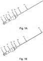
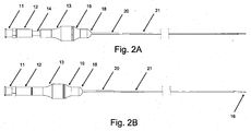
- crossing device 1 may include body 13, microcatheter 21, handle 12, and blade 16. According to embodiments, crossing device 1 allows for a handheld mechanical penetration of an occlusion. Surgeons and interventionalists have expressed ongoing needs for devices leveraging their "hand" or feel for manipulating devices in situ.
- body 13 may be attached to microcatheter 21, and handle 12 may be attached to blade 16, such that handle 12 is moveable relative to body 13, and movement of handle 12 relative to body 13 causes advancement and retraction of blade 16 along the inner portion of microcatheter 21.
- Figs. 1A and 2A show crossing device 1 in a natural position, with handle 12 and blade 16 retracted;
- Figs. 1 B and 2B show crossing device 1 in an extended position, with handle 12 and blade 16 extended.
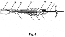
- handle 12 may include or be combined with one or more of luer 11, plunger rod 14, hypo support 15, and blade 16.
- handle 12, luer 11, plunger rod 14, hypo support 15, and blade 16 may be combined to form an integrated unit.
- One or more interfaces e.g., threading, etc.
- fixations e.g., adhesive, epoxy, etc.
- body 13 may include or be combined with one or more of nose guide 19, nose 18, heat shrink 20, and microcatheter 21.
- nose guide 19, nose 18, heat shrink 20, and microcatheter 21 may be combined to form an integrated unit.
- One or more interfaces e.g., threading, etc.
- fixations e.g., adhesive, epoxy, etc.
- spring 17 may be disposed between at least a portion of handle 12 and at least a portion of body 13.
- spring 17 extends between plunger rod 14-which is attached to handle 12-and nose guide 19-which is attached to body 13.
- spring 17 may tend to separate handle 12 from body 13 by way of elastic expansion.
- Handle 12 and body 13 may be configured to set a limit on the separation.
- plunger rod 14 may include a flange that contacts a portion of body 13 to prevent travel along the axis beyond a certain point.
- nose 18 may be separate from and attachable to nose guide 19. Nose 18 may be fixably attached to microcatheter 21 and removably attached to nose guide 19, such that a microcatheter may be exchanged by removing nose 18. Such an option avoids the need to replace an entire system for need of a new microcatheter.
- crossing device 1 may facilitate use of a guidewire.
- Blade 16 may be configured with a hollow inner portion to allow a guidewire to be advanced from a proximal end of blade 16 to a distal end of blade 16.
- a guidewire lumen within blade 16 may be configured to accommodate any guidewire used for general vascular surgical procedures, such that a separate or distinct guidewire is not required for operation of crossing device 1.
- Such technology is known in the art are the following U.S. patent applications and publications: U.S. Patent No. 6,066,149 , U.S. Patent No. 5,972,019 , U.S. Patent No. 5,695,469 , U.S. Patent No. 6,506,178 , U.S. Patent No. 6,533,753 , U.S.
- Patent No. 6,579,302 U.S. Patent No. 6,663,577 , U.S. Patent No. 7,399,291 , U.S. Patent No. 5,879,305 , U.S. Patent No. 5,724,977 , U.S. Patent No. 5,596,990 , U.S. Publication No. 2004/0230219 , U.S. Publication No. 2005/0209559 , U.S. Publication No. 2007/0265563 , U.S. Publication No. 2005/0049574 , U.S. Publication No. 2006/0184186 , U.S. Publication No. 2001/0031981 , U.S. Publication No.
- 2007/0208368 U.S. Publication No. 2007/0021685 , U.S. Publication No. 2008/0097247 , U.S. Publication No. 2008/0140101 , U.S. Publication No. 2008/0114390 , U.S. Publication No. 2008/0228171 , and U.S. Publication No. 2008/0249465 .
- a luer 11 may be configured to interface with handle 12, as shown in Figs. 3 and 4 .
- Luer 11 may be a detachable hub/luer device configured to direct devices to microcatheter 21.
- Luer 11 may facilitate use of a support catheter, PTA balloon catheter, guidewire, or another lumen-configured or catheter-based supplemental treatment device to be exchanged with components of crossing device 1 during use, without removal of crossing device 1 from a patient.
- Such a configuration provides the ability to operate crossing device 1 in tandem or in sequence with other devices intended to deliver treatment to the same or nearby location.
- devices advanced within the lumen of blade 16 or otherwise provided through luer 11 may be operated, manipulated, and moved either along with or independent of handle 12, body 13, or their associated attached components.
- blade 16 may be configured to penetrate an occlusion upon contact with the occlusion.
- the distal end of blade 16 may include one of a variety of shapes to facilitate addressing the occlusion. Examples are shown in Figs. 5A and 5B .
- blade 16 may include an everted end, an end with a sharpened tip, a concave end, a convex end, a coring tip, or other geometry to address an occlusion.
- Blade 16 may be hollow or solid.
- microcatheter 21 and blade 16 may provide sufficient flexibility to provide trackability within vessels of a patient. Microcatheter 21 and blade 16 may also provided sufficient rigidity to adequately transfer translational and rotational forces to be responsive at a distal end to a user located at a proximal end. According to embodiments, a tip at a distal end section of blade 16 may be relatively rigid, to provide a force of impact to an occlusion upon extension of the same.
- blade 16 may be configured to provide rotational motion at the point of deployment (e.g., at or near the distal end of crossing device 1). For example, as a user provides torque to handle 12, the torque may be translated along blade 16 to the distal end of blade 16. A torque provided at the distal end may improve treatment of the occlusion. The torque may be applied and translated before, during, or after extension of blade 16 beyond the distal end of microcatheter 21 and penetration of the occlusion.
- blade 16 may be configured to automatically rotate as it advances longitudinally relative to microcatheter 21.
- threading may be provided about the axis along which blade 16 travels, such that travel of blade 16 along the axis also results in rotation of blade 16.
- microcatheter 21 may be provided on at least a portion of its inner surface with threading, channels, or other guiding members to govern the manner in which blade 16 is advanced and retracted therein.
- Blade 16 may be provided with threading or other features to complement the guiding members of the axis along which blade 16 travels.
- at least a portion of blade 16 may have a substantially spiral geometry adapted to interface with a complementary threading of microcatheter 21.
- blade 16 may be configured to penetrate or cross a section of an occlusion. According to embodiments, at least a portion of the occlusion may be captured or enclosed by features of blade 16. For example, ridges, protrusions, edges, and spiral geometries may be provided at the distal end of blade 16 to capture or enclose at least a portion of the occlusion that is penetrated by blade 16. Subsequently, blade 16 may be retracted, whereby at least a portion of the occlusion is removed by blade 16.
- blade 16 may be advanced relative to microcatheter 21 with simultaneous longitudinal and rotational motion, whereby the spiral geometry captures at least a portion of the occlusion. Subsequently, blade 16 may be retracted longitudinally, whereby the portions of the occlusion are maintained within the spiral geometry. For example, blade 16 may be retracted with microcatheter 21.
- the foregoing may result in a path within the occlusion which may be the object of further operations, such as by the same device or others, or may be a path that at least partially restores a flow of blood and reperfusion through the occlusion.
- blade 16 may be configured to be entirely or almost entirely disposed within microcatheter 21 at its distal end when crossing device 1 is in a natural position, as shown in Figs. 1A and 2A , and to be somewhat extended beyond the distal end of microcatheter 21 when crossing device 1 is in an extended position, as shown in Figs. 1B and 2B .
- blade 16 may be configured to lock relative to microcatheter 21 when in a natural position or an extended position.
- Mechanisms to selectively or automatically lock and unlock blade 16 may be provided and may be operable by a user located at a proximal end of crossing device 1 to activate or deactivate said mechanisms.
- crossing device 1 may be configured as either an "over the wire” device (see Fig. 4 ) or a "rapid exchange” device (not shown).
- supplemental devices may be configured to interface with crossing device 1 in a rapid exchange configuration.
- Crossing device 1 may include at least one lumen to accommodate a supplemental device to be used in conjunction with other components of crossing device 1.
- a rapid exchange lumen may entry access at or near a proximal end of crossing device 1 and may extend to the distal end of crossing device 1 (e.g., the distal end of microcatheter 21).
- crossing device 1 may be used to address an occlusion.
- the distal end of crossing device 1, including a portion of microcatheter 21, blade 16, or a guidewire, may be brought to the location of an occlusion.
- the guidewire may first be brought to the occlusion, followed by microcatheter 21 and blade 16.
- Blade 16 may be extended beyond the distal end of microcatheter 21 by operation of handle 12, as disclosed herein.
- increased advancement of microcatheter 21, blade 16, or a guidewire may be provided.
- Increased advancement of microcatheter 21, blade 16, or a guidewire may provide an improved position of the same to continue the crossing procedure in iterative steps. The process may be repeated in successive steps until the occlusion is crossed as desired.
- Microcatheter 21 may be brought to an occlusion, such as a heavily calcified lesion or other obstruction, as discussed herein.
- Blade 16 may be advanced by crossing device 1 such that it penetrates the occlusion. Blade 16 may retract when handle 12 is released, by the function of spring 17.
- a PTA balloon, stent device, or other catheter-based supplemental treatment device may operate within a channel created by operation of crossing device 1.
- crossing device 1 may provide increased perfusion of fluid flow through the channel created by crossing device 1.
- the increased perfusion may provide improved conditions to facilitate breakdown of the occlusion, such that perfusion alone or in combination with other methods may remove threats presented by the occlusion.
- spring 17 may be omitted such that handle 12 may travel relative to body 13 along the axis within certain limitations, such that the user may selectively and manually advance and retract blade 16 relative to.microcatheter 21.
- crossing device 1 may be configured to allow blade 16 to be extended in a natural position and retracted based on action taken by a user (not shown).
- the configuration shown in Fig. 4 may be modified such that spring 17 is located such that its tendency toward elastic expansion causes handle 12 to be advanced toward body 13.
- retraction of handle 12 may compress spring 17, such that release of handle 12 causes advancement of blade 16 toward or beyond the distal end of microcatheter 21.
- crossing device 1 may include two springs to provide novel use and performance characteristics (not shown). For example, one spring may tend toward extension of blade 16, and another spring may tend toward retraction of blade 16. Blade 16 may be configured such that the distal tip of blade 16 is in a desired location when equilibrium between the two springs is achieved in a natural position. A user may selectively advance or retract blade 16 by operation of handle 12, and release for blade 16 to allow release of any energy stored in the springs, with the blade 16 eventually reaching equilibrium in a natural position.
- kits of parts are disclosed.
- the kits of parts including at least one component disclose herein and configured to perform at least one of the exemplary methods herein disclosed.
- directions for use (“DFU") are included and the device may be part of a surgical tray or other packaged accessory set for surgeries.
- the kit may be a sub-component of a surgical tray.
- each physical element disclosed should be understood to encompass a disclosure of the action which that physical element facilitates.
Landscapes
- Health & Medical Sciences (AREA)
- Surgery (AREA)
- Life Sciences & Earth Sciences (AREA)
- Medical Informatics (AREA)
- Nuclear Medicine, Radiotherapy & Molecular Imaging (AREA)
- Engineering & Computer Science (AREA)
- Biomedical Technology (AREA)
- Heart & Thoracic Surgery (AREA)
- Vascular Medicine (AREA)
- Molecular Biology (AREA)
- Animal Behavior & Ethology (AREA)
- General Health & Medical Sciences (AREA)
- Public Health (AREA)
- Veterinary Medicine (AREA)
- Surgical Instruments (AREA)
- Media Introduction/Drainage Providing Device (AREA)
Description
- This disclosure relates to systems and apparatus for treating humans via allopathic or surgical intervention, minimally invasive surgical practices, endovascular procedures, percutaneous procedures, and related medical procedures. Specifically, this disclosure relates to systems for addressing vessel lumen-based issues and treatment of occlusions within a body, including those related to peripheral vascular disease states, cardiovascular diseases, cerebrovascular diseases, and others.
- Document D1 (
WO 01/54588 - Improved crossing devices are disclosed for treatment of occlusions within a body, owing to the paucity of effective devices available clinically, and the longstanding needs in this field of art. The invention is disclosed in claim 1. Preferred embodiments are disclosed in the dependent claims.
- According to embodiments, a crossing device is disclosed, comprising: a body coupled to a microcatheter at a proximal end of the microcatheter; a handle coupled to a blade at a proximal end of the blade, the blade disposed within a lumen of the microcatheter; and the microcatheter and blade are flexible to provide trackability within vessels of a patient, and wherein the blade is configured to receive a guidewire for delivery to a target treatment site within a blood vessel of a patient, and further wherein the blade is configured to move axially and rotationally relative to the microcatheter, chacterised by; a spring, wherein the spring is configured to compress to advance a sharpened tip of the blade from a natural position within the lumen of the microcatheter to an extended position beyond a distal end of the microcatheter as the handle is advanced relative to the body, wherein the spring is configured to expand and retract the blade relative to the microcatheter as the handle is released.
- The crossing device may further comprise a luer configured to attach to a proximal end of the handle and provide adaptable use of a supplemental treatment device in combination with the crossing device. The luer may be configured to guide a supplemental treatment device to the lumen of the microcatheter or a lumen of the blade. The supplemental treatment device may be at least one of: a guidewire, a PTA balloon, and a stent device.
- The tip of the blade may be disposed at a distal end of the blade and is of a rigid material. The tip of the blade may be a hollow, sharpened, everted tip.
- The handle and the body may be configured to limit the expansion of the spring and provide the natural position of the blade and further configured to selectively lock the blade in at least one of the natural position and the extended position. The body may further comprise a nose detachable from the body and secured to the microcatheter, such that the microcatheter is selectively removable from the body.
- An exemplary surgical method for addressing blockage within a vessel is disclosed, comprising, in combination: delivering an apparatus including at least a microcatheter to a desired treatment situs; positioning the microcatheter having at least a blade proximate to a surface of an occlusion, wherein the microcatheter is attached to a body and comprises a lumen; providing the blade within the lumen of the microcatheter to the surface of the occlusion, wherein the blade is attached to a handle; advancing the blade to an extended position by manipulation of the handle relative to the body; and retracting the blade to a natural position by releasing the handle.
- The blade may be retracted by a spring between the handle and the body. The method may result in reconfiguration of at least a portion of the occlusion, whereby a different flow condition may be achieved.
- The method may further comprise advancing the microcatheter and the blade through a channel created by advancement of the blade to an extended position. The method may further comprise providing a supplemental treatment device to the occlusion through a lumen of the blade. The supplemental treatment device may be at least one of a guidewire, a PTA balloon, and a stent device.
- According to embodiments, a kit is disclosed, comprising: a crossing device further comprising: a body coupled to a microcatheter at a proximal end of the microcatheter; a handle coupled to a blade at a proximal end of the blade, the blade disposed within a lumen of the microcatheter; and the microcatheter and blade are flexible to provide trackability within vessels of a patient, and wherein the blade is configured to receive a guidewire for delivery to a target treatment site within a blood vessel of a patient, and further wherein the blade Is configured to move axially and rotationally relative to the microcatheter, chacterised by; a spring, wherein the spring is configured to compress to advance a sharpened tip of the blade from a natural position within the lumen of the microcatheter to an extended position beyond a distal end of the microcatheter as the handle is advanced relative to the body,
- The kit may further comprise a supplemental treatment device configured to be advanced within the lumen of the microcatheter. The kit may further comprise a luer disposed at a proximal end of the handle and configured to guide the supplemental treatment device into the lumen of the microcatheter. The supplemental treatment device may be at least one of: a guidewire, a PTA balloon, and a stent device.
- A system for addressing obstructions within lumens of the disclosure, comprising, in combination: a body coupled to a microcatheter at a proximal end of the microcatheter; a handle coupled to a blade at a proximal end of the blade, the blade disposed within a lumen of the microcatheter; a luer configured to attach to a proximal end of the handle and provide adaptable use of a supplemental treatment device in combination with the crossing device; a spring configured to compress as the handle is advanced relative to the body; wherein a tip of the blade may be configured to advance from a natural position within the lumen of the microcatheter to an extended position beyond a distal end of the microcatheter as the handle is advanced relative to the body; wherein the spring may be configured to expand and retract the blade relative to the microcatheter as the handle is released.
- The above-mentioned features and objects of the present disclosure will become more apparent with reference to the following description taken in conjunction with the accompanying drawings wherein like reference numerals denote like elements and in which:
-
Figure 1A is a schematic view of an embodiment of a crossing device in a natural position, according to embodiments of the present disclosure; -
Figure 1 B is a schematic view of an embodiment of a crossing device in an extended position, according to embodiments of the present disclosure; -
Figure 2A is a schematic view of an embodiment of a crossing device in a natural position, according to embodiments of the present disclosure; -
Figure 2B is a schematic view of an embodiment of a crossing device in an extended position, according to embodiments of the present disclosure; -
Figure 3 is an exploded view of an embodiment of a crossing device, according to embodiments of the present disclosure; -
Figure 4 is a cross-sectional view of an embodiment of a crossing device, according to embodiments of the present disclosure; -
Figure 5A is a schematic view of an embodiment of a blade of a crossing device, according to embodiments of the present disclosure; and -
Figure 5B is a schematic view of an embodiment of a blade of a crossing device, according to embodiments of the present disclosure. - The present inventors have discovered that treatment of conditions, including chronic total occlusions, remain challenged by the paucity of extent devices. Namely, surgeons require improved apparatus to impact, address, and ameliorate occlusions by thrombi, emboli, and other obstructions in real time during procedures.
- In the following detailed description of embodiments of the present disclosure, reference is made to the accompanying drawings in which like references indicate similar elements, and in which is shown by way of illustration specific embodiments in which the present disclosure may be practiced. These embodiments are described in sufficient detail to enable those skilled in the art to practice the present disclosure, and it is to be understood that other embodiments may be utilized and that logical, mechanical, electrical, functional, and other changes may be made without departing from the scope of the present disclosure. The following detailed description is, therefore, not to be taken in a limiting sense, and the scope of the present disclosure is defined only by the appended claims. As used in the present disclosure, the term "or" shall be understood to be defined as a logical disjunction and shall not indicate an exclusive disjunction unless expressly indicated as such or notated as "xor."
- The inventors of the present disclosure have invented and reduced to practice improved systems, comprised of devices for ablating, crossing, or cutting an occlusion including known constraints of managing fluid-flow and other access issues within a body, particularly in the lumen of vessels. The devices discussed herein may be employed for medical treatment and in conjunction with other devices for medical treatment, as known to those skilled in the art.
- Where a patient is indicated for certain treatment, monitoring, or intervention or suffers from a disease, a lumen of a blood vessel or other fluid-bearing vessel may become occluded. For example, a chronic total occlusion ("CTO") or other partial or total obstruction of a blood vessel may occur or be the result of a thrombus, an embolism, atherosclerosis, or other disease that results in a blockage, restriction, or occlusion of fluid flow within a body. Often, during procedures, situations arise requiring immediate intervention, such as to address a CTO.
- Where treatment of an occlusion by endovascular procedure is desired, medical professionals may attempt endovascular surgical procedures. Endovascular procedures include angioplasty procedures, stent placement, various scope procedures, and plethoric diagnostic, intermediary and interlocutory clot addressing schemes, which may include temporarily or permanently emplaced devices.
- An occlusion may include a fibrous cap, composed of lipids, endothelial cells, macrophages, smooth muscle cells, foam cells, connective tissue, and other vascular materials. An occlusion may include calcification, such that the occlusion becomes hardened. Under these conditions, various endovascular procedures including thrombectomy, angioplasty, stent placement, retrieval of an obstruction, and others may be complicated or prevented by the difficulty or inability to penetrate the occlusion. For example, such procedures may require at least partial penetration of an occlusion before the procedure may be commenced or completed. Often, establishing some degree of reperfusion is critical.
- According to embodiments, as shown in
Figs. 1A, 1 B, 2A, and 2B , crossing device 1 may includebody 13,microcatheter 21,handle 12, andblade 16. According to embodiments, crossing device 1 allows for a handheld mechanical penetration of an occlusion. Surgeons and interventionalists have expressed ongoing needs for devices leveraging their "hand" or feel for manipulating devices in situ. - According to embodiments,
body 13 may be attached tomicrocatheter 21, andhandle 12 may be attached toblade 16, such thathandle 12 is moveable relative tobody 13, and movement ofhandle 12 relative tobody 13 causes advancement and retraction ofblade 16 along the inner portion ofmicrocatheter 21.Figs. 1A and2A show crossing device 1 in a natural position, withhandle 12 andblade 16 retracted;Figs. 1 B and 2B show crossing device 1 in an extended position, withhandle 12 andblade 16 extended. - According to embodiments,
handle 12 may include or be combined with one or more ofluer 11,plunger rod 14,hypo support 15, andblade 16. For example, as shown inFigs. 3 and4 ,handle 12,luer 11,plunger rod 14,hypo support 15, andblade 16 may be combined to form an integrated unit. One or more interfaces (e.g., threading, etc.) or fixations (e.g., adhesive, epoxy, etc.) may be provided to combine said components. - According to embodiments,
body 13 may include or be combined with one or more ofnose guide 19,nose 18, heat shrink 20, andmicrocatheter 21. For example, as shown inFigs. 3 and4 ,body 13,nose guide 19,nose 18, heat shrink 20, andmicrocatheter 21 may be combined to form an integrated unit. One or more interfaces (e.g., threading, etc.) or fixations (e.g., adhesive, epoxy, etc.) may be provided to combine said components. - According to embodiments,
spring 17 may be disposed between at least a portion ofhandle 12 and at least a portion ofbody 13. For example, as shown inFig. 4 ,spring 17 extends between plunger rod 14-which is attached to handle 12-and nose guide 19-which is attached tobody 13. - According to embodiments,
spring 17 may tend to separate handle 12 frombody 13 by way of elastic expansion.Handle 12 andbody 13 may be configured to set a limit on the separation. For example, as shown inFigs. 3 and4 ,plunger rod 14 may include a flange that contacts a portion ofbody 13 to prevent travel along the axis beyond a certain point. - According to embodiments,
nose 18 may be separate from and attachable tonose guide 19.Nose 18 may be fixably attached to microcatheter 21 and removably attached tonose guide 19, such that a microcatheter may be exchanged by removingnose 18. Such an option avoids the need to replace an entire system for need of a new microcatheter. - According to embodiments, crossing device 1 may facilitate use of a guidewire.
Blade 16 may be configured with a hollow inner portion to allow a guidewire to be advanced from a proximal end ofblade 16 to a distal end ofblade 16. A guidewire lumen withinblade 16 may be configured to accommodate any guidewire used for general vascular surgical procedures, such that a separate or distinct guidewire is not required for operation of crossing device 1. Such technology is known in the art are the following U.S. patent applications and publications:U.S. Patent No. 6,066,149 ,U.S. Patent No. 5,972,019 ,U.S. Patent No. 5,695,469 ,U.S. Patent No. 6,506,178 ,U.S. Patent No. 6,533,753 ,U.S. Patent No. 6,579,302 ,U.S. Patent No. 6,663,577 ,U.S. Patent No. 7,399,291 ,U.S. Patent No. 5,879,305 ,U.S. Patent No. 5,724,977 ,U.S. Patent No. 5,596,990 ,U.S. Publication No. 2004/0230219 ,U.S. Publication No. 2005/0209559 ,U.S. Publication No. 2007/0265563 ,U.S. Publication No. 2005/0049574 ,U.S. Publication No. 2006/0184186 ,U.S. Publication No. 2001/0031981 ,U.S. Publication No. 2007/0208368 ,U.S. Publication No. 2007/0021685 ,U.S. Publication No. 2008/0097247 ,U.S. Publication No. 2008/0140101 ,U.S. Publication No. 2008/0114390 ,U.S. Publication No. 2008/0228171 , andU.S. Publication No. 2008/0249465 . - According to embodiments, a
luer 11 may be configured to interface withhandle 12, as shown inFigs. 3 and4 .Luer 11 may be a detachable hub/luer device configured to direct devices to microcatheter 21.Luer 11 may facilitate use of a support catheter, PTA balloon catheter, guidewire, or another lumen-configured or catheter-based supplemental treatment device to be exchanged with components of crossing device 1 during use, without removal of crossing device 1 from a patient. Such a configuration provides the ability to operate crossing device 1 in tandem or in sequence with other devices intended to deliver treatment to the same or nearby location. - According to embodiments, devices advanced within the lumen of
blade 16 or otherwise provided throughluer 11 may be operated, manipulated, and moved either along with or independent ofhandle 12,body 13, or their associated attached components. - According to embodiments,
blade 16 may be configured to penetrate an occlusion upon contact with the occlusion. The distal end ofblade 16 may include one of a variety of shapes to facilitate addressing the occlusion. Examples are shown inFigs. 5A and 5B . For example,blade 16 may include an everted end, an end with a sharpened tip, a concave end, a convex end, a coring tip, or other geometry to address an occlusion.Blade 16 may be hollow or solid. - According to embodiments,
microcatheter 21 andblade 16 may provide sufficient flexibility to provide trackability within vessels of a patient.Microcatheter 21 andblade 16 may also provided sufficient rigidity to adequately transfer translational and rotational forces to be responsive at a distal end to a user located at a proximal end. According to embodiments, a tip at a distal end section ofblade 16 may be relatively rigid, to provide a force of impact to an occlusion upon extension of the same. - According to embodiments,
blade 16 may be configured to provide rotational motion at the point of deployment (e.g., at or near the distal end of crossing device 1). For example, as a user provides torque to handle 12, the torque may be translated alongblade 16 to the distal end ofblade 16. A torque provided at the distal end may improve treatment of the occlusion. The torque may be applied and translated before, during, or after extension ofblade 16 beyond the distal end ofmicrocatheter 21 and penetration of the occlusion. - According to embodiments,
blade 16 may be configured to automatically rotate as it advances longitudinally relative tomicrocatheter 21. For example, threading may be provided about the axis along whichblade 16 travels, such that travel ofblade 16 along the axis also results in rotation ofblade 16. For example, microcatheter 21 may be provided on at least a portion of its inner surface with threading, channels, or other guiding members to govern the manner in whichblade 16 is advanced and retracted therein.Blade 16 may be provided with threading or other features to complement the guiding members of the axis along whichblade 16 travels. For example, at least a portion ofblade 16 may have a substantially spiral geometry adapted to interface with a complementary threading ofmicrocatheter 21. - According to embodiments,
blade 16 may be configured to penetrate or cross a section of an occlusion. According to embodiments, at least a portion of the occlusion may be captured or enclosed by features ofblade 16. For example, ridges, protrusions, edges, and spiral geometries may be provided at the distal end ofblade 16 to capture or enclose at least a portion of the occlusion that is penetrated byblade 16. Subsequently,blade 16 may be retracted, whereby at least a portion of the occlusion is removed byblade 16. - For example, where
blade 16 includes a substantially spiral geometry,blade 16 may be advanced relative to microcatheter 21 with simultaneous longitudinal and rotational motion, whereby the spiral geometry captures at least a portion of the occlusion. Subsequently,blade 16 may be retracted longitudinally, whereby the portions of the occlusion are maintained within the spiral geometry. For example,blade 16 may be retracted withmicrocatheter 21. The foregoing may result in a path within the occlusion which may be the object of further operations, such as by the same device or others, or may be a path that at least partially restores a flow of blood and reperfusion through the occlusion. - According to embodiments,
blade 16 may be configured to be entirely or almost entirely disposed withinmicrocatheter 21 at its distal end when crossing device 1 is in a natural position, as shown inFigs. 1A and2A , and to be somewhat extended beyond the distal end ofmicrocatheter 21 when crossing device 1 is in an extended position, as shown inFigs. 1B and2B . - According to embodiments,
blade 16 may be configured to lock relative to microcatheter 21 when in a natural position or an extended position. Mechanisms to selectively or automatically lock and unlockblade 16 may be provided and may be operable by a user located at a proximal end of crossing device 1 to activate or deactivate said mechanisms. - According to embodiments, crossing device 1 may be configured as either an "over the wire" device (see
Fig. 4 ) or a "rapid exchange" device (not shown). For example, supplemental devices may be configured to interface with crossing device 1 in a rapid exchange configuration. Crossing device 1 may include at least one lumen to accommodate a supplemental device to be used in conjunction with other components of crossing device 1. For example, a rapid exchange lumen may entry access at or near a proximal end of crossing device 1 and may extend to the distal end of crossing device 1 (e.g., the distal end of microcatheter 21). - According to embodiments, crossing device 1 may be used to address an occlusion. The distal end of crossing device 1, including a portion of
microcatheter 21,blade 16, or a guidewire, may be brought to the location of an occlusion. For example, the guidewire may first be brought to the occlusion, followed bymicrocatheter 21 andblade 16.Blade 16 may be extended beyond the distal end ofmicrocatheter 21 by operation ofhandle 12, as disclosed herein. As the occlusion is penetrated, increased advancement ofmicrocatheter 21,blade 16, or a guidewire may be provided. Increased advancement ofmicrocatheter 21,blade 16, or a guidewire may provide an improved position of the same to continue the crossing procedure in iterative steps. The process may be repeated in successive steps until the occlusion is crossed as desired. - An exemplary method for causing
blade 16 to penetrate an occlusion is disclosed.Microcatheter 21 may be brought to an occlusion, such as a heavily calcified lesion or other obstruction, as discussed herein.Blade 16 may be advanced by crossing device 1 such that it penetrates the occlusion.Blade 16 may retract when handle 12 is released, by the function ofspring 17. - The above described steps may be repeated as desired. For example, the above described steps may be repeated until the occlusion is entirely breached or until sufficient access is provided for other devices to act upon the occlusion. For example, a PTA balloon, stent device, or other catheter-based supplemental treatment device may operate within a channel created by operation of crossing device 1.
- The method and use of crossing device 1 may provide increased perfusion of fluid flow through the channel created by crossing device 1. The increased perfusion may provide improved conditions to facilitate breakdown of the occlusion, such that perfusion alone or in combination with other methods may remove threats presented by the occlusion.
- According to embodiments, variations on embodiments may be made to provide customizable use and performance characteristics of crossing device 1. For example,
spring 17 may be omitted such that handle 12 may travel relative tobody 13 along the axis within certain limitations, such that the user may selectively and manually advance and retractblade 16relative to.microcatheter 21. - According to embodiments of the disclosure, crossing device 1 may be configured to allow
blade 16 to be extended in a natural position and retracted based on action taken by a user (not shown). The configuration shown inFig. 4 may be modified such thatspring 17 is located such that its tendency toward elastic expansion causes handle 12 to be advanced towardbody 13. In such a configuration, retraction ofhandle 12 may compressspring 17, such that release ofhandle 12 causes advancement ofblade 16 toward or beyond the distal end ofmicrocatheter 21. - According to embodiments, crossing device 1 may include two springs to provide novel use and performance characteristics (not shown). For example, one spring may tend toward extension of
blade 16, and another spring may tend toward retraction ofblade 16.Blade 16 may be configured such that the distal tip ofblade 16 is in a desired location when equilibrium between the two springs is achieved in a natural position. A user may selectively advance or retractblade 16 by operation ofhandle 12, and release forblade 16 to allow release of any energy stored in the springs, with theblade 16 eventually reaching equilibrium in a natural position. - According to embodiments, a kit of parts is disclosed. One or more kits of parts can be envisioned by the person skilled in the art, the kits of parts including at least one component disclose herein and configured to perform at least one of the exemplary methods herein disclosed. Likewise, directions for use ("DFU") are included and the device may be part of a surgical tray or other packaged accessory set for surgeries. The kit may be a sub-component of a surgical tray.
- It is intended to cover various modifications and similar arrangements included within the scope of the claims, the scope of which should be accorded the broadest interpretation so as to encompass all such modifications and similar structures. The present disclosure includes any and all embodiments of the following claims.
- Such changes are also implicitly included in the description. They still fall within the scope of this invention. It should be understood that this disclosure is intended to yield a patent covering numerous aspects of the invention both independently and as an overall system.
- Further, each of the various elements of the invention and claims may also be achieved in a variety of manners. This disclosure should be understood to encompass each such variation, be it a variation of an embodiment of any apparatus embodiment or even merely a variation of any element of these.
- Particularly, it should be understood that as the disclosure relates to elements of the invention, the words for each element may be expressed by equivalent apparatus terms - even if only the function or result is the same.
- Such equivalent, broader, or even more generic terms should be considered to be encompassed in the description of each element or action. Such terms can be substituted where desired to make explicit the implicitly broad coverage to which this invention is entitled.
- It should be understood that all actions may be expressed as a means for taking that action or as an element which causes that action.
- Similarly, each physical element disclosed should be understood to encompass a disclosure of the action which that physical element facilitates.
- In addition, as to each term used it should be understood that unless its utilization in this application is inconsistent with such interpretation, common dictionary definitions should be understood as incorporated for each term and all definitions, alternative terms, and synonyms such as contained in at least one of a standard technical dictionary recognized by artisans and the Random House Webster's Unabridged Dictionary.
- Further, the use of the transitional phrase "comprising" is used to maintain the "open-end" claims herein, according to traditional claim interpretation. Thus, unless the context requires otherwise, it should be understood that the term "compromise" or variations such as "comprises" or "comprising", are intended to imply the inclusion of a stated element or step or group of elements or steps but not the exclusion of any other element or step or group of elements or steps.
- Such terms should be interpreted in their most expansive forms so as to afford the applicant the broadest coverage legally permissible.
Claims (15)
- A crossing device (1) suitable for tracking within the vessels of a patient and penetrating through an occlusion in the vessel, comprising:a body (13) coupled to a microcatheter (21) at a proximal end of the microcatheter (21); a handle (12) coupled to a blade (16) at a proximal end of the blade (16),wherein the blade (16) is disposed within a lumen of the microcatheter (21), and the microcatheter (21) and blade (16) are flexible to provide trackability within vessels of a patient, and wherein the blade (16) is configured to receive a guidewire for intravascular delivery to a target treatment site within a blood vessel of the patient, and further wherein the blade (16) is configured to move axially and rotationally relative to the microcatheter (21); andcharacterized by a spring (17),wherein the spring (17) is configured to compress to advance a sharpened tip of the blade (16) axially outward from a natural position within the lumen of the microcatheter (21) to an extended position beyond a distal end of the microcatheter as the handle (12) is advanced relative to the body (13),wherein the spring (17) is configured to expand to axially retract the blade (16) from the extended position toward the natural position within the lumen of the microcatheter (21) as the handle (12) is moved proximally.
- The crossing device of claim 1, further comprising a luer (11) configured to be attached to a proximal end of the handle (12), wherein the luer (11) is configured to facilitate use of a supplemental treatment device in combination with the crossing device (1).
- The crossing device of claim 2 wherein the luer (11) is configured to guide a supplemental treatment device to the lumen of the microcatheter (21).
- The crossing device of claim 2 wherein the luer (11) is configured to guide a supplemental treatment device to a lumen of the blade (16).
- The crossing device of claim 2 wherein the supplemental treatment device comprises at least one of the following: a guidewire, a PTA balloon, and a stent device.
- The crossing device of claim 2, further comprising a plunger rod (14) and a hypo support (15), and wherein the handle (12), luer (11), plunger rod (14), hypo support (15), and blade (16) comprise an integrated unit.
- The crossing device of any one of claims 1 to 6 wherein the tip of the blade (16) comprises a rigid material.
- The crossing device of any one of claims 1 to 7 wherein the tip of the blade (16) comprises a hollow, sharpened, everted tip.
- The crossing device of any one of claims 1 to 8 wherein the handle (12) and the body (13) are configured to limit the expansion of the spring (17) and provide the natural position of the blade (16), and wherein the handle (12) is further configured to selectively lock the blade (16) in at least one of the natural position and the extended position.
- The crossing device of any one of claims 1 to 9 wherein the body (13) of the crossing device (1) further comprises a nose (18) detachable from the body (13) and releasably secured to the microcatheter (21), and wherein the microcatheter (21) is selectively removable from the body (13).
- The crossing device of any one of claims 1 to 10 wherein the lumen of the microcatheter (21) further comprises guiding members configured to provide torque to the blade (16) as the blade (16) is advanced from the natural position to the extended position.
- The crossing device of any one of claims I to 11 wherein the tip of the blade (16) comprises a concave end or a convex end.
- The crossing device of any one of claims 1 to 12 wherein the crossing device (1) is configured as a rapid exchange device.
- The crossing device of any one of claims 1 to 13, further comprising a nose guide (19), a nose (18), and a heat shrink portion (20), and wherein the body (13), nose guide (19), nose (18), heat shrink portion (20), and microcatheter (21) comprise an integrated unit.
- A kit which comprises:the crossing device (1) according to any one of claims 1 to 14; anddirections for use
Applications Claiming Priority (4)
| Application Number | Priority Date | Filing Date | Title |
|---|---|---|---|
| US23932109P | 2009-09-02 | 2009-09-02 | |
| PCT/US2009/055950 WO2011028203A1 (en) | 2009-09-02 | 2009-09-03 | Systems, methods and devices for ablation, crossing, and cutting of occlusions |
| US12/570,677 US9204893B2 (en) | 2009-09-02 | 2009-09-30 | Systems, methods and devices for ablation, crossing, and cutting of occlusions |
| PCT/US2010/047170 WO2011028665A2 (en) | 2009-09-02 | 2010-08-30 | Systems, methods and devices for ablation, crossing, and cutting of occlusions |
Publications (3)
| Publication Number | Publication Date |
|---|---|
| EP2473122A2 EP2473122A2 (en) | 2012-07-11 |
| EP2473122A4 EP2473122A4 (en) | 2014-01-15 |
| EP2473122B1 true EP2473122B1 (en) | 2016-08-10 |
Family
ID=43649541
Family Applications (1)
| Application Number | Title | Priority Date | Filing Date |
|---|---|---|---|
| EP10814335.5A Active EP2473122B1 (en) | 2009-09-02 | 2010-08-30 | Systems and devices for ablation, crossing, and cutting of occlusions |
Country Status (7)
| Country | Link |
|---|---|
| US (3) | US9204893B2 (en) |
| EP (1) | EP2473122B1 (en) |
| JP (1) | JP6050682B2 (en) |
| CN (1) | CN102762159B (en) |
| AU (1) | AU2010289659B2 (en) |
| CA (1) | CA2772024C (en) |
| WO (2) | WO2011028203A1 (en) |
Cited By (1)
| Publication number | Priority date | Publication date | Assignee | Title |
|---|---|---|---|---|
| WO2023017006A1 (en) | 2021-08-10 | 2023-02-16 | Biotronik Ag | Crossing catheter system for crossing chronic total occlusion and a method for operating the crossing catheter system |
Families Citing this family (23)
| Publication number | Priority date | Publication date | Assignee | Title |
|---|---|---|---|---|
| US11219750B2 (en) | 2008-03-21 | 2022-01-11 | Cagent Vascular, Inc. | System and method for plaque serration |
| US9480826B2 (en) | 2008-03-21 | 2016-11-01 | Cagent Vascular, Llc | Intravascular device |
| WO2009117158A2 (en) | 2008-03-21 | 2009-09-24 | Innovasc Llc | Device and method for opening blood vessels by pre-angioplasty serration and dilatation of aetherosclerotic plaque |
| US20110034937A1 (en) * | 2009-08-07 | 2011-02-10 | TD.JAM Medical Technologies, LLC | Revascularization Device for Treating an Occluded Arterial Vessel |
| WO2011028203A1 (en) | 2009-09-02 | 2011-03-10 | Reflow Medical Inc. | Systems, methods and devices for ablation, crossing, and cutting of occlusions |
| WO2014012011A1 (en) * | 2012-07-13 | 2014-01-16 | Boston Scientific Scimed, Inc. | Wire-guided recanalization system |
| CN103300938B (en) * | 2013-06-27 | 2015-05-20 | 中国医学科学院阜外心血管病医院 | Trans-atrial pathway atrioventricular valve regurgitation animal modeling device |
| EP3035876B1 (en) | 2013-09-18 | 2018-11-14 | Xablecath Inc. | Device and system for crossing and treating an occlusion |
| US10463842B2 (en) | 2014-06-04 | 2019-11-05 | Cagent Vascular, Llc | Cage for medical balloon |
| WO2016027198A1 (en) * | 2014-08-21 | 2016-02-25 | Koninklijke Philips N.V. | Device and methods for crossing occlusions |
| EP3215212B1 (en) | 2014-11-03 | 2020-07-29 | Cagent Vascular, LLC | Serration balloon |
| US10322269B1 (en) | 2015-01-19 | 2019-06-18 | Dalent, LLC | Dilator device |
| CN104887293B (en) * | 2015-05-07 | 2017-08-04 | 刘春晓 | A kind of binary channels tissue Cutting instrument for cervical intervertebral disc hyperplasia and its application method for possessing auxiliary pouring function |
| EP3799919A1 (en) | 2015-09-17 | 2021-04-07 | Cagent Vascular, LLC | Wedge dissectors for a medical ballon |
| WO2018094077A1 (en) | 2016-11-16 | 2018-05-24 | Cagent Vascular, Llc | Systems and methods of depositing drug into tissue through serrations |
| CN108378896A (en) * | 2018-01-11 | 2018-08-10 | 恩脉(上海)医疗科技有限公司 | Dredging conduit for interventional treatment |
| US11642500B2 (en) | 2018-02-20 | 2023-05-09 | Crossliner, Inc. | Intravascular delivery system and method for percutaneous coronary intervention |
| US11491313B2 (en) | 2018-02-20 | 2022-11-08 | Crossliner, Inc. | Guide catheter extension system with a delivery micro-catheter configured to facilitate percutaneous coronary intervention |
| US20190255299A1 (en) * | 2018-02-20 | 2019-08-22 | Crossliner, Llc | Intravascular delivery system and method for percutaneous coronary intervention |
| CA3105746A1 (en) | 2018-07-25 | 2020-01-30 | Cagent Vascular, Llc | Medical balloon catheters with enhanced pushability |
| USD877325S1 (en) | 2019-06-06 | 2020-03-03 | Dalent, LLC | Inflatable therapeutic treatment balloon device |
| CN114901163A (en) | 2019-11-01 | 2022-08-12 | 瑞弗罗医疗公司 | Extraction device with protruding features for thrombectomy |
| US11712266B2 (en) | 2021-06-25 | 2023-08-01 | Vantis Vascular, Inc. | Enhanced guide extension system for the efficient delivery of leads |
Citations (1)
| Publication number | Priority date | Publication date | Assignee | Title |
|---|---|---|---|---|
| US5423846A (en) * | 1991-10-21 | 1995-06-13 | Cathco, Inc. | Dottering auger catheter system |
Family Cites Families (71)
| Publication number | Priority date | Publication date | Assignee | Title |
|---|---|---|---|---|
| DE3520524A1 (en) | 1985-06-07 | 1986-12-11 | Richard Wolf Gmbh, 7134 Knittlingen | INSTRUMENT FOR SLITING STENOSES IN BODY CHANNELS |
| US4627841A (en) | 1986-02-18 | 1986-12-09 | Dorr Robert T | Infusion needle |
| US5053044A (en) | 1988-01-11 | 1991-10-01 | Devices For Vascular Intervention, Inc. | Catheter and method for making intravascular incisions |
| US5330432A (en) | 1991-12-06 | 1994-07-19 | Inbae Yoon | Retractable safety penetrating instrument |
| US5186712A (en) * | 1991-08-23 | 1993-02-16 | Kansas Creative Devices, Inc. | Intravenous catheter launching device |
| US5376075A (en) * | 1993-08-31 | 1994-12-27 | Haughton; Victor M. | Catheter sharp retraction system |
| FR2710539B1 (en) | 1993-09-30 | 1995-12-22 | Becton Dickinson Co | Set of surgical needle. |
| US5425718A (en) * | 1993-10-22 | 1995-06-20 | Tay; Sew-Wah | Self-sticking needle assembly and method for insertion into an artery |
| US5527282A (en) | 1994-12-09 | 1996-06-18 | Segal; Jerome | Vascular dilatation device and method |
| US5596990A (en) | 1995-06-06 | 1997-01-28 | Yock; Paul | Rotational correlation of intravascular ultrasound image with guide catheter position |
| CA2234389A1 (en) | 1995-10-13 | 1997-04-17 | Transvascular, Inc. | A device, system and method for interstitial transvascular intervention |
| US5936671A (en) * | 1996-07-02 | 1999-08-10 | Sharp Laboratories Of America, Inc. | Object-based video processing using forward-tracking 2-D mesh layers |
| US5972019A (en) | 1996-07-25 | 1999-10-26 | Target Therapeutics, Inc. | Mechanical clot treatment device |
| US6066149A (en) | 1997-09-30 | 2000-05-23 | Target Therapeutics, Inc. | Mechanical clot treatment device with distal filter |
| US5938671A (en) | 1997-11-14 | 1999-08-17 | Reflow, Inc. | Recanalization apparatus and devices for use therein and method |
| US5935108A (en) * | 1997-11-14 | 1999-08-10 | Reflow, Inc. | Recanalization apparatus and devices for use therein and method |
| US6217527B1 (en) | 1998-09-30 | 2001-04-17 | Lumend, Inc. | Methods and apparatus for crossing vascular occlusions |
| US20080140101A1 (en) | 2006-12-07 | 2008-06-12 | Revascular Therapeutic, Inc. | Apparatus for crossing occlusions or stenoses |
| US6540725B1 (en) | 1998-06-04 | 2003-04-01 | Biosense Webster, Inc. | Injection catheter with controllably extendable injection needle |
| US6159198A (en) * | 1998-07-16 | 2000-12-12 | Medtronic, Inc. | Introducer system |
| US6080175A (en) * | 1998-07-29 | 2000-06-27 | Corvascular, Inc. | Surgical cutting instrument and method of use |
| US20090093791A1 (en) | 1999-09-17 | 2009-04-09 | Heuser Richard R | Devices and methods for treating chronic total occlusion |
| US20070265563A1 (en) * | 2006-05-11 | 2007-11-15 | Heuser Richard R | Device for treating chronic total occlusion |
| BR0104246A (en) * | 2000-01-26 | 2002-05-21 | Heartport Inc | Vascular incisor and method |
| US20010031981A1 (en) | 2000-03-31 | 2001-10-18 | Evans Michael A. | Method and device for locating guidewire and treating chronic total occlusions |
| US6533753B1 (en) | 2000-04-07 | 2003-03-18 | Philip Haarstad | Apparatus and method for the treatment of an occluded lumen |
| JP4754147B2 (en) * | 2000-04-18 | 2011-08-24 | エム ディー シー インベストメント ホールディングス インコーポレイテッド | Shielded medical device with retractable needle member |
| US6506178B1 (en) | 2000-11-10 | 2003-01-14 | Vascular Architects, Inc. | Apparatus and method for crossing a position along a tubular body structure |
| US6579302B2 (en) | 2001-03-06 | 2003-06-17 | Cordis Corporation | Total occlusion guidewire device |
| US6666847B2 (en) | 2001-05-18 | 2003-12-23 | Us Endoscopy Group, Inc. | Duodenoscope needle |
| US6663577B2 (en) | 2001-12-07 | 2003-12-16 | Abbott Laboratories | Catheter deployment device |
| US20040230219A1 (en) | 2003-05-12 | 2004-11-18 | Roucher Leo R. | Anchoring, supporting and centering catheter system for treating chronic total occlusions |
| DE602004025366D1 (en) | 2003-07-02 | 2010-03-18 | Cook Inc | Coaxial catheter |
| US7763012B2 (en) | 2003-09-02 | 2010-07-27 | St. Jude Medical, Cardiology Division, Inc. | Devices and methods for crossing a chronic total occlusion |
| DE20316804U1 (en) | 2003-10-31 | 2005-03-10 | B. Braun Melsungen Ag | catheter device |
| US7320695B2 (en) | 2003-12-31 | 2008-01-22 | Biosense Webster, Inc. | Safe septal needle and method for its use |
| WO2005089850A2 (en) | 2004-03-19 | 2005-09-29 | Medtronic Vascular, Inc. | Apparatus and methods for the treatment of chronic total occlusions |
| US20060004323A1 (en) | 2004-04-21 | 2006-01-05 | Exploramed Nc1, Inc. | Apparatus and methods for dilating and modifying ostia of paranasal sinuses and other intranasal or paranasal structures |
| US20060293612A1 (en) * | 2004-06-24 | 2006-12-28 | Boston Scientific Scimed, Inc. | Apparatus and method for treating occluded vasculature |
| US8241315B2 (en) | 2004-06-24 | 2012-08-14 | Boston Scientific Scimed, Inc. | Apparatus and method for treating occluded vasculature |
| WO2006058195A2 (en) * | 2004-11-23 | 2006-06-01 | Pneumrx, Inc. | Steerable device for accessing a target site and methods |
| US7399291B2 (en) | 2004-12-02 | 2008-07-15 | Syntheon, Llc. | Catheter for treatment of total occlusions and methods for manufacture and use of the catheter |
| US20060184186A1 (en) | 2005-02-16 | 2006-08-17 | Medtronic Vascular, Inc. | Drilling guidewire for treating chronic total occlusion |
| US20070021685A1 (en) | 2005-05-04 | 2007-01-25 | Abbott Laboratories Abbott Vascular Devices | Guidewire apparatus with an expandable portion and methods of use |
| US20080188793A1 (en) * | 2007-02-06 | 2008-08-07 | Possis Medical, Inc. | Miniature flexible thrombectomy catheter |
| AU2007215224B2 (en) | 2006-02-13 | 2011-05-12 | Retrovascular, Inc. | Recanalizing occluded vessels using controlled antegrade and retrograde tracking |
| US8007506B2 (en) | 2006-06-30 | 2011-08-30 | Atheromed, Inc. | Atherectomy devices and methods |
| US8361094B2 (en) | 2006-06-30 | 2013-01-29 | Atheromed, Inc. | Atherectomy devices and methods |
| US8419658B2 (en) | 2006-09-06 | 2013-04-16 | Boston Scientific Scimed, Inc. | Medical device including structure for crossing an occlusion in a vessel |
| US7682365B2 (en) | 2006-11-13 | 2010-03-23 | Medtronic Vascular, Inc. | Catheter device for support of a guidewire in crossing a lesion |
| US10888354B2 (en) | 2006-11-21 | 2021-01-12 | Bridgepoint Medical, Inc. | Endovascular devices and methods for exploiting intramural space |
| US8257383B2 (en) | 2007-03-29 | 2012-09-04 | Boston Scientific Limited | Lumen reentry devices and methods |
| US8852223B2 (en) | 2007-04-06 | 2014-10-07 | Cordis Corporation | Fixed wire dilatation catheter with an elongateable distal end |
| US20080294145A1 (en) * | 2007-05-25 | 2008-11-27 | Galt Medical Corporation | Catheter hub with flushable lumen and guidewire |
| US8070762B2 (en) | 2007-10-22 | 2011-12-06 | Atheromed Inc. | Atherectomy devices and methods |
| US8276589B2 (en) * | 2007-12-21 | 2012-10-02 | Massachusetts Eye & Ear Infirmary | Cricothyrotomy device |
| WO2009100129A2 (en) | 2008-02-05 | 2009-08-13 | Chad John Kugler | Crossing occlusions in blood vessels |
| US8062316B2 (en) | 2008-04-23 | 2011-11-22 | Avinger, Inc. | Catheter system and method for boring through blocked vascular passages |
| US20100125253A1 (en) | 2008-11-17 | 2010-05-20 | Avinger | Dual-tip Catheter System for Boring through Blocked Vascular Passages |
| US9498600B2 (en) | 2009-07-01 | 2016-11-22 | Avinger, Inc. | Atherectomy catheter with laterally-displaceable tip |
| CN100574716C (en) | 2008-05-22 | 2009-12-30 | 尹建明 | Rotary cutter for treating skin disease |
| US20100056862A1 (en) | 2008-09-03 | 2010-03-04 | Ethicon Endo-Surgery, Inc. | Access needle for natural orifice translumenal endoscopic surgery |
| WO2010129075A1 (en) | 2009-04-28 | 2010-11-11 | Avinger, Inc. | Guidewire support catheter |
| US20110034937A1 (en) | 2009-08-07 | 2011-02-10 | TD.JAM Medical Technologies, LLC | Revascularization Device for Treating an Occluded Arterial Vessel |
| WO2011028203A1 (en) | 2009-09-02 | 2011-03-10 | Reflow Medical Inc. | Systems, methods and devices for ablation, crossing, and cutting of occlusions |
| US20120265229A1 (en) | 2009-09-03 | 2012-10-18 | Dan Rottenberg | Lancet micro-catheter |
| US20110208222A1 (en) | 2010-02-25 | 2011-08-25 | Boris Ljahnicky | System and Method for the Treatment of Occluded Vessels |
| EP2588012B1 (en) | 2010-07-01 | 2016-08-17 | Avinger, Inc. | Atherectomy catheters with longitudinally displaceable drive shafts |
| KR101518147B1 (en) | 2010-10-28 | 2015-05-06 | 코비디엔 엘피 | Material removal device and method of use |
| WO2012145133A2 (en) | 2011-03-28 | 2012-10-26 | Avinger, Inc. | Occlusion-crossing devices, imaging, and atherectomy devices |
| US8956376B2 (en) | 2011-06-30 | 2015-02-17 | The Spectranetics Corporation | Reentry catheter and method thereof |
-
2009
- 2009-09-03 WO PCT/US2009/055950 patent/WO2011028203A1/en active Application Filing
- 2009-09-30 US US12/570,677 patent/US9204893B2/en active Active
-
2010
- 2010-08-30 JP JP2012527953A patent/JP6050682B2/en active Active
- 2010-08-30 CN CN201080049452.9A patent/CN102762159B/en active Active
- 2010-08-30 WO PCT/US2010/047170 patent/WO2011028665A2/en active Application Filing
- 2010-08-30 AU AU2010289659A patent/AU2010289659B2/en active Active
- 2010-08-30 EP EP10814335.5A patent/EP2473122B1/en active Active
- 2010-08-30 CA CA2772024A patent/CA2772024C/en active Active
-
2012
- 2012-10-09 US US13/648,144 patent/US20130035750A1/en not_active Abandoned
-
2015
- 2015-04-09 US US14/682,782 patent/US20150209063A1/en not_active Abandoned
Patent Citations (1)
| Publication number | Priority date | Publication date | Assignee | Title |
|---|---|---|---|---|
| US5423846A (en) * | 1991-10-21 | 1995-06-13 | Cathco, Inc. | Dottering auger catheter system |
Cited By (1)
| Publication number | Priority date | Publication date | Assignee | Title |
|---|---|---|---|---|
| WO2023017006A1 (en) | 2021-08-10 | 2023-02-16 | Biotronik Ag | Crossing catheter system for crossing chronic total occlusion and a method for operating the crossing catheter system |
Also Published As
| Publication number | Publication date |
|---|---|
| EP2473122A4 (en) | 2014-01-15 |
| AU2010289659B2 (en) | 2015-07-30 |
| CN102762159B (en) | 2015-06-17 |
| US20110054503A1 (en) | 2011-03-03 |
| CN102762159A (en) | 2012-10-31 |
| WO2011028665A3 (en) | 2011-09-29 |
| WO2011028665A2 (en) | 2011-03-10 |
| CA2772024C (en) | 2018-01-02 |
| JP6050682B2 (en) | 2016-12-21 |
| WO2011028203A1 (en) | 2011-03-10 |
| EP2473122A2 (en) | 2012-07-11 |
| US20130035750A1 (en) | 2013-02-07 |
| US20150209063A1 (en) | 2015-07-30 |
| US9204893B2 (en) | 2015-12-08 |
| CA2772024A1 (en) | 2011-03-10 |
| JP2013503701A (en) | 2013-02-04 |
| AU2010289659A1 (en) | 2012-03-22 |
Similar Documents
| Publication | Publication Date | Title |
|---|---|---|
| EP2473122B1 (en) | Systems and devices for ablation, crossing, and cutting of occlusions | |
| US11786269B2 (en) | Atherectomy devices and methods | |
| US8747332B2 (en) | Guidewire for crossing occlusions or stenoses | |
| EP2037821B1 (en) | Atherectomy devices | |
| AU2021283979A1 (en) | Recapturable funnel catheters, and associated systems and methods | |
| US20110144677A1 (en) | Methods and Systems for Bypassing an Occlusion in a Blood Vessel | |
| JP2016533861A (en) | System and method for crossing and treating an obstruction | |
| US10357275B2 (en) | Dual-basket self-centering rotational device for treatment of arterial occlusive disease with infinitely adjustable cutting size | |
| CN111053593B (en) | Formable reentry devices and systems and methods therefor | |
| US20090093829A1 (en) | Chronic total occlusion (CTO) removal device | |
| JP6820611B2 (en) | Double concentric guide wire | |
| WO2022221643A1 (en) | Devices, systems, and methods for removing obstructive material from body lumens | |
| US20230091211A1 (en) | Re-entry catheter | |
| US20240197347A1 (en) | Devices, systems, and methods for removing obstructive material from body lumens | |
| CA2488588C (en) | Guidewire for crossing occlusions or stenosis |
Legal Events
| Date | Code | Title | Description |
|---|---|---|---|
| PUAI | Public reference made under article 153(3) epc to a published international application that has entered the european phase |
Free format text: ORIGINAL CODE: 0009012 |
|
| 17P | Request for examination filed |
Effective date: 20120323 |
|
| AK | Designated contracting states |
Kind code of ref document: A2 Designated state(s): AL AT BE BG CH CY CZ DE DK EE ES FI FR GB GR HR HU IE IS IT LI LT LU LV MC MK MT NL NO PL PT RO SE SI SK SM TR |
|
| DAX | Request for extension of the european patent (deleted) | ||
| A4 | Supplementary search report drawn up and despatched |
Effective date: 20131213 |
|
| 17Q | First examination report despatched |
Effective date: 20150723 |
|
| RIC1 | Information provided on ipc code assigned before grant |
Ipc: A61B 17/3205 20060101AFI20150922BHEP Ipc: A61M 25/10 20130101ALI20150922BHEP Ipc: A61M 29/00 20060101ALI20150922BHEP Ipc: A61M 25/09 20060101ALI20150922BHEP |
|
| GRAP | Despatch of communication of intention to grant a patent |
Free format text: ORIGINAL CODE: EPIDOSNIGR1 |
|
| INTG | Intention to grant announced |
Effective date: 20160315 |
|
| RAP1 | Party data changed (applicant data changed or rights of an application transferred) |
Owner name: REFLOW MEDICAL, INC. |
|
| RIN1 | Information on inventor provided before grant (corrected) |
Inventor name: FULKERSON, JOHN Inventor name: RIZK, ISA |
|
| GRAS | Grant fee paid |
Free format text: ORIGINAL CODE: EPIDOSNIGR3 |
|
| GRAA | (expected) grant |
Free format text: ORIGINAL CODE: 0009210 |
|
| AK | Designated contracting states |
Kind code of ref document: B1 Designated state(s): AL AT BE BG CH CY CZ DE DK EE ES FI FR GB GR HR HU IE IS IT LI LT LU LV MC MK MT NL NO PL PT RO SE SI SK SM TR |
|
| REG | Reference to a national code |
Ref country code: GB Ref legal event code: FG4D |
|
| REG | Reference to a national code |
Ref country code: CH Ref legal event code: EP Ref country code: AT Ref legal event code: REF Ref document number: 818229 Country of ref document: AT Kind code of ref document: T Effective date: 20160815 |
|
| REG | Reference to a national code |
Ref country code: IE Ref legal event code: FG4D |
|
| REG | Reference to a national code |
Ref country code: DE Ref legal event code: R096 Ref document number: 602010035450 Country of ref document: DE |
|
| REG | Reference to a national code |
Ref country code: LT Ref legal event code: MG4D |
|
| REG | Reference to a national code |
Ref country code: NL Ref legal event code: MP Effective date: 20160810 |
|
| REG | Reference to a national code |
Ref country code: AT Ref legal event code: MK05 Ref document number: 818229 Country of ref document: AT Kind code of ref document: T Effective date: 20160810 |
|
| PG25 | Lapsed in a contracting state [announced via postgrant information from national office to epo] |
Ref country code: NO Free format text: LAPSE BECAUSE OF FAILURE TO SUBMIT A TRANSLATION OF THE DESCRIPTION OR TO PAY THE FEE WITHIN THE PRESCRIBED TIME-LIMIT Effective date: 20161110 Ref country code: FI Free format text: LAPSE BECAUSE OF FAILURE TO SUBMIT A TRANSLATION OF THE DESCRIPTION OR TO PAY THE FEE WITHIN THE PRESCRIBED TIME-LIMIT Effective date: 20160810 Ref country code: IS Free format text: LAPSE BECAUSE OF FAILURE TO SUBMIT A TRANSLATION OF THE DESCRIPTION OR TO PAY THE FEE WITHIN THE PRESCRIBED TIME-LIMIT Effective date: 20161210 Ref country code: LT Free format text: LAPSE BECAUSE OF FAILURE TO SUBMIT A TRANSLATION OF THE DESCRIPTION OR TO PAY THE FEE WITHIN THE PRESCRIBED TIME-LIMIT Effective date: 20160810 Ref country code: IT Free format text: LAPSE BECAUSE OF FAILURE TO SUBMIT A TRANSLATION OF THE DESCRIPTION OR TO PAY THE FEE WITHIN THE PRESCRIBED TIME-LIMIT Effective date: 20160810 Ref country code: NL Free format text: LAPSE BECAUSE OF FAILURE TO SUBMIT A TRANSLATION OF THE DESCRIPTION OR TO PAY THE FEE WITHIN THE PRESCRIBED TIME-LIMIT Effective date: 20160810 |
|
| REG | Reference to a national code |
Ref country code: FR Ref legal event code: PLFP Year of fee payment: 7 |
|
| PG25 | Lapsed in a contracting state [announced via postgrant information from national office to epo] |
Ref country code: LV Free format text: LAPSE BECAUSE OF FAILURE TO SUBMIT A TRANSLATION OF THE DESCRIPTION OR TO PAY THE FEE WITHIN THE PRESCRIBED TIME-LIMIT Effective date: 20160810 Ref country code: BE Free format text: LAPSE BECAUSE OF NON-PAYMENT OF DUE FEES Effective date: 20160831 Ref country code: SE Free format text: LAPSE BECAUSE OF FAILURE TO SUBMIT A TRANSLATION OF THE DESCRIPTION OR TO PAY THE FEE WITHIN THE PRESCRIBED TIME-LIMIT Effective date: 20160810 Ref country code: AT Free format text: LAPSE BECAUSE OF FAILURE TO SUBMIT A TRANSLATION OF THE DESCRIPTION OR TO PAY THE FEE WITHIN THE PRESCRIBED TIME-LIMIT Effective date: 20160810 Ref country code: PL Free format text: LAPSE BECAUSE OF FAILURE TO SUBMIT A TRANSLATION OF THE DESCRIPTION OR TO PAY THE FEE WITHIN THE PRESCRIBED TIME-LIMIT Effective date: 20160810 Ref country code: PT Free format text: LAPSE BECAUSE OF FAILURE TO SUBMIT A TRANSLATION OF THE DESCRIPTION OR TO PAY THE FEE WITHIN THE PRESCRIBED TIME-LIMIT Effective date: 20161212 Ref country code: ES Free format text: LAPSE BECAUSE OF FAILURE TO SUBMIT A TRANSLATION OF THE DESCRIPTION OR TO PAY THE FEE WITHIN THE PRESCRIBED TIME-LIMIT Effective date: 20160810 Ref country code: GR Free format text: LAPSE BECAUSE OF FAILURE TO SUBMIT A TRANSLATION OF THE DESCRIPTION OR TO PAY THE FEE WITHIN THE PRESCRIBED TIME-LIMIT Effective date: 20161111 |
|
| REG | Reference to a national code |
Ref country code: CH Ref legal event code: PL |
|
| PG25 | Lapsed in a contracting state [announced via postgrant information from national office to epo] |
Ref country code: EE Free format text: LAPSE BECAUSE OF FAILURE TO SUBMIT A TRANSLATION OF THE DESCRIPTION OR TO PAY THE FEE WITHIN THE PRESCRIBED TIME-LIMIT Effective date: 20160810 Ref country code: LI Free format text: LAPSE BECAUSE OF NON-PAYMENT OF DUE FEES Effective date: 20160831 Ref country code: RO Free format text: LAPSE BECAUSE OF FAILURE TO SUBMIT A TRANSLATION OF THE DESCRIPTION OR TO PAY THE FEE WITHIN THE PRESCRIBED TIME-LIMIT Effective date: 20160810 Ref country code: CH Free format text: LAPSE BECAUSE OF NON-PAYMENT OF DUE FEES Effective date: 20160831 |
|
| REG | Reference to a national code |
Ref country code: DE Ref legal event code: R097 Ref document number: 602010035450 Country of ref document: DE |
|
| PG25 | Lapsed in a contracting state [announced via postgrant information from national office to epo] |
Ref country code: BG Free format text: LAPSE BECAUSE OF FAILURE TO SUBMIT A TRANSLATION OF THE DESCRIPTION OR TO PAY THE FEE WITHIN THE PRESCRIBED TIME-LIMIT Effective date: 20161110 Ref country code: SK Free format text: LAPSE BECAUSE OF FAILURE TO SUBMIT A TRANSLATION OF THE DESCRIPTION OR TO PAY THE FEE WITHIN THE PRESCRIBED TIME-LIMIT Effective date: 20160810 Ref country code: DK Free format text: LAPSE BECAUSE OF FAILURE TO SUBMIT A TRANSLATION OF THE DESCRIPTION OR TO PAY THE FEE WITHIN THE PRESCRIBED TIME-LIMIT Effective date: 20160810 Ref country code: SM Free format text: LAPSE BECAUSE OF FAILURE TO SUBMIT A TRANSLATION OF THE DESCRIPTION OR TO PAY THE FEE WITHIN THE PRESCRIBED TIME-LIMIT Effective date: 20160810 Ref country code: CZ Free format text: LAPSE BECAUSE OF FAILURE TO SUBMIT A TRANSLATION OF THE DESCRIPTION OR TO PAY THE FEE WITHIN THE PRESCRIBED TIME-LIMIT Effective date: 20160810 Ref country code: BE Free format text: LAPSE BECAUSE OF FAILURE TO SUBMIT A TRANSLATION OF THE DESCRIPTION OR TO PAY THE FEE WITHIN THE PRESCRIBED TIME-LIMIT Effective date: 20160810 |
|
| REG | Reference to a national code |
Ref country code: IE Ref legal event code: MM4A |
|
| PLBE | No opposition filed within time limit |
Free format text: ORIGINAL CODE: 0009261 |
|
| STAA | Information on the status of an ep patent application or granted ep patent |
Free format text: STATUS: NO OPPOSITION FILED WITHIN TIME LIMIT |
|
| PG25 | Lapsed in a contracting state [announced via postgrant information from national office to epo] |
Ref country code: MC Free format text: LAPSE BECAUSE OF FAILURE TO SUBMIT A TRANSLATION OF THE DESCRIPTION OR TO PAY THE FEE WITHIN THE PRESCRIBED TIME-LIMIT Effective date: 20160810 |
|
| REG | Reference to a national code |
Ref country code: FR Ref legal event code: PLFP Year of fee payment: 8 |
|
| 26N | No opposition filed |
Effective date: 20170511 |
|
| PG25 | Lapsed in a contracting state [announced via postgrant information from national office to epo] |
Ref country code: IE Free format text: LAPSE BECAUSE OF NON-PAYMENT OF DUE FEES Effective date: 20160830 |
|
| PG25 | Lapsed in a contracting state [announced via postgrant information from national office to epo] |
Ref country code: LU Free format text: LAPSE BECAUSE OF NON-PAYMENT OF DUE FEES Effective date: 20160830 Ref country code: SI Free format text: LAPSE BECAUSE OF FAILURE TO SUBMIT A TRANSLATION OF THE DESCRIPTION OR TO PAY THE FEE WITHIN THE PRESCRIBED TIME-LIMIT Effective date: 20160810 |
|
| PG25 | Lapsed in a contracting state [announced via postgrant information from national office to epo] |
Ref country code: HU Free format text: LAPSE BECAUSE OF FAILURE TO SUBMIT A TRANSLATION OF THE DESCRIPTION OR TO PAY THE FEE WITHIN THE PRESCRIBED TIME-LIMIT; INVALID AB INITIO Effective date: 20100830 Ref country code: CY Free format text: LAPSE BECAUSE OF FAILURE TO SUBMIT A TRANSLATION OF THE DESCRIPTION OR TO PAY THE FEE WITHIN THE PRESCRIBED TIME-LIMIT Effective date: 20160810 |
|
| PG25 | Lapsed in a contracting state [announced via postgrant information from national office to epo] |
Ref country code: HR Free format text: LAPSE BECAUSE OF FAILURE TO SUBMIT A TRANSLATION OF THE DESCRIPTION OR TO PAY THE FEE WITHIN THE PRESCRIBED TIME-LIMIT Effective date: 20160810 Ref country code: MT Free format text: LAPSE BECAUSE OF NON-PAYMENT OF DUE FEES Effective date: 20160831 Ref country code: MK Free format text: LAPSE BECAUSE OF FAILURE TO SUBMIT A TRANSLATION OF THE DESCRIPTION OR TO PAY THE FEE WITHIN THE PRESCRIBED TIME-LIMIT Effective date: 20160810 Ref country code: TR Free format text: LAPSE BECAUSE OF FAILURE TO SUBMIT A TRANSLATION OF THE DESCRIPTION OR TO PAY THE FEE WITHIN THE PRESCRIBED TIME-LIMIT Effective date: 20160810 |
|
| REG | Reference to a national code |
Ref country code: FR Ref legal event code: PLFP Year of fee payment: 9 |
|
| PG25 | Lapsed in a contracting state [announced via postgrant information from national office to epo] |
Ref country code: AL Free format text: LAPSE BECAUSE OF FAILURE TO SUBMIT A TRANSLATION OF THE DESCRIPTION OR TO PAY THE FEE WITHIN THE PRESCRIBED TIME-LIMIT Effective date: 20160810 |
|
| REG | Reference to a national code |
Ref country code: DE Ref legal event code: R082 Ref document number: 602010035450 Country of ref document: DE Representative=s name: WEIDNER STERN JESCHKE PATENTANWAELTE PARTNERSC, DE |
|
| PGFP | Annual fee paid to national office [announced via postgrant information from national office to epo] |
Ref country code: GB Payment date: 20230706 Year of fee payment: 14 |
|
| PGFP | Annual fee paid to national office [announced via postgrant information from national office to epo] |
Ref country code: FR Payment date: 20230703 Year of fee payment: 14 Ref country code: DE Payment date: 20230705 Year of fee payment: 14 |