EP3035876B1 - Device and system for crossing and treating an occlusion - Google Patents
Device and system for crossing and treating an occlusion Download PDFInfo
- Publication number
- EP3035876B1 EP3035876B1 EP14845424.2A EP14845424A EP3035876B1 EP 3035876 B1 EP3035876 B1 EP 3035876B1 EP 14845424 A EP14845424 A EP 14845424A EP 3035876 B1 EP3035876 B1 EP 3035876B1
- Authority
- EP
- European Patent Office
- Prior art keywords
- clearing device
- occlusion
- catheter
- tip
- guidewire
- Prior art date
- Legal status (The legal status is an assumption and is not a legal conclusion. Google has not performed a legal analysis and makes no representation as to the accuracy of the status listed.)
- Active
Links
- 230000003902 lesion Effects 0.000 claims description 61
- 239000000463 material Substances 0.000 claims description 34
- 210000005166 vasculature Anatomy 0.000 claims description 14
- 210000004204 blood vessel Anatomy 0.000 claims description 12
- 239000012530 fluid Substances 0.000 claims description 11
- 239000011248 coating agent Substances 0.000 claims description 9
- 238000000576 coating method Methods 0.000 claims description 9
- 238000004891 communication Methods 0.000 claims description 5
- 230000004048 modification Effects 0.000 claims description 4
- 238000012986 modification Methods 0.000 claims description 4
- 238000000034 method Methods 0.000 description 64
- 208000031481 Pathologic Constriction Diseases 0.000 description 56
- 230000036262 stenosis Effects 0.000 description 56
- 208000037804 stenosis Diseases 0.000 description 56
- 238000011282 treatment Methods 0.000 description 24
- 210000001519 tissue Anatomy 0.000 description 20
- 238000002399 angioplasty Methods 0.000 description 15
- 238000003384 imaging method Methods 0.000 description 10
- 208000030613 peripheral artery disease Diseases 0.000 description 8
- 206010003210 Arteriosclerosis Diseases 0.000 description 7
- 208000037260 Atherosclerotic Plaque Diseases 0.000 description 7
- 238000013459 approach Methods 0.000 description 7
- 230000017531 blood circulation Effects 0.000 description 6
- 230000006835 compression Effects 0.000 description 6
- 238000007906 compression Methods 0.000 description 6
- 229920000642 polymer Polymers 0.000 description 6
- 238000002560 therapeutic procedure Methods 0.000 description 6
- 210000001367 artery Anatomy 0.000 description 5
- 230000008901 benefit Effects 0.000 description 5
- 230000000694 effects Effects 0.000 description 5
- 229920002614 Polyether block amide Polymers 0.000 description 4
- 206010053648 Vascular occlusion Diseases 0.000 description 4
- 238000005299 abrasion Methods 0.000 description 4
- 230000009471 action Effects 0.000 description 4
- 210000001105 femoral artery Anatomy 0.000 description 4
- 239000012216 imaging agent Substances 0.000 description 4
- 230000002093 peripheral effect Effects 0.000 description 4
- 239000000853 adhesive Substances 0.000 description 3
- 230000001070 adhesive effect Effects 0.000 description 3
- 210000004369 blood Anatomy 0.000 description 3
- 239000008280 blood Substances 0.000 description 3
- 230000001684 chronic effect Effects 0.000 description 3
- 239000002872 contrast media Substances 0.000 description 3
- 229920000295 expanded polytetrafluoroethylene Polymers 0.000 description 3
- 238000002347 injection Methods 0.000 description 3
- 239000007924 injection Substances 0.000 description 3
- 230000003993 interaction Effects 0.000 description 3
- 230000036346 tooth eruption Effects 0.000 description 3
- 230000002792 vascular Effects 0.000 description 3
- 239000004642 Polyimide Substances 0.000 description 2
- 206010057469 Vascular stenosis Diseases 0.000 description 2
- 230000004888 barrier function Effects 0.000 description 2
- 238000005452 bending Methods 0.000 description 2
- 238000010276 construction Methods 0.000 description 2
- 230000008878 coupling Effects 0.000 description 2
- 238000010168 coupling process Methods 0.000 description 2
- 238000005859 coupling reaction Methods 0.000 description 2
- 238000002224 dissection Methods 0.000 description 2
- 210000003811 finger Anatomy 0.000 description 2
- 210000003090 iliac artery Anatomy 0.000 description 2
- 208000014674 injury Diseases 0.000 description 2
- 239000002184 metal Substances 0.000 description 2
- 229920001721 polyimide Polymers 0.000 description 2
- 238000002601 radiography Methods 0.000 description 2
- 208000037803 restenosis Diseases 0.000 description 2
- 239000010963 304 stainless steel Substances 0.000 description 1
- 201000001320 Atherosclerosis Diseases 0.000 description 1
- 241001503987 Clematis vitalba Species 0.000 description 1
- 208000036376 Femoral artery occlusion Diseases 0.000 description 1
- 241000909536 Gobiesocidae Species 0.000 description 1
- 208000032026 No-Reflow Phenomenon Diseases 0.000 description 1
- 239000004677 Nylon Substances 0.000 description 1
- 208000030831 Peripheral arterial occlusive disease Diseases 0.000 description 1
- 206010063837 Reperfusion injury Diseases 0.000 description 1
- 229910000589 SAE 304 stainless steel Inorganic materials 0.000 description 1
- 239000004809 Teflon Substances 0.000 description 1
- 229920006362 Teflon® Polymers 0.000 description 1
- 208000027418 Wounds and injury Diseases 0.000 description 1
- 230000001154 acute effect Effects 0.000 description 1
- 239000000956 alloy Substances 0.000 description 1
- 229910045601 alloy Inorganic materials 0.000 description 1
- 238000002266 amputation Methods 0.000 description 1
- 230000003143 atherosclerotic effect Effects 0.000 description 1
- 230000000747 cardiac effect Effects 0.000 description 1
- 239000000919 ceramic Substances 0.000 description 1
- 230000008859 change Effects 0.000 description 1
- 239000002131 composite material Substances 0.000 description 1
- 210000002808 connective tissue Anatomy 0.000 description 1
- 229940039231 contrast media Drugs 0.000 description 1
- 238000007796 conventional method Methods 0.000 description 1
- 210000004351 coronary vessel Anatomy 0.000 description 1
- 230000006378 damage Effects 0.000 description 1
- 238000000502 dialysis Methods 0.000 description 1
- 239000013070 direct material Substances 0.000 description 1
- 239000003814 drug Substances 0.000 description 1
- 229940079593 drug Drugs 0.000 description 1
- 238000012377 drug delivery Methods 0.000 description 1
- 230000010102 embolization Effects 0.000 description 1
- 210000003414 extremity Anatomy 0.000 description 1
- 210000004247 hand Anatomy 0.000 description 1
- 210000003127 knee Anatomy 0.000 description 1
- 210000002414 leg Anatomy 0.000 description 1
- 150000002632 lipids Chemical class 0.000 description 1
- 239000000314 lubricant Substances 0.000 description 1
- 230000014759 maintenance of location Effects 0.000 description 1
- 239000000203 mixture Substances 0.000 description 1
- 230000003387 muscular Effects 0.000 description 1
- 229920001778 nylon Polymers 0.000 description 1
- 210000005259 peripheral blood Anatomy 0.000 description 1
- 239000011886 peripheral blood Substances 0.000 description 1
- 239000004417 polycarbonate Substances 0.000 description 1
- 229920000515 polycarbonate Polymers 0.000 description 1
- 229920001296 polysiloxane Polymers 0.000 description 1
- 229920001343 polytetrafluoroethylene Polymers 0.000 description 1
- 239000004810 polytetrafluoroethylene Substances 0.000 description 1
- 238000007639 printing Methods 0.000 description 1
- 230000008569 process Effects 0.000 description 1
- 230000000750 progressive effect Effects 0.000 description 1
- 230000001681 protective effect Effects 0.000 description 1
- 230000005855 radiation Effects 0.000 description 1
- 230000002787 reinforcement Effects 0.000 description 1
- 229910052710 silicon Inorganic materials 0.000 description 1
- 239000010703 silicon Substances 0.000 description 1
- 239000007787 solid Substances 0.000 description 1
- 230000000153 supplemental effect Effects 0.000 description 1
- 210000003813 thumb Anatomy 0.000 description 1
- 230000008733 trauma Effects 0.000 description 1
- 238000011144 upstream manufacturing Methods 0.000 description 1
- 238000012800 visualization Methods 0.000 description 1
- 238000004804 winding Methods 0.000 description 1
- 239000002023 wood Substances 0.000 description 1
Images


Classifications
-
- A—HUMAN NECESSITIES
- A61—MEDICAL OR VETERINARY SCIENCE; HYGIENE
- A61B—DIAGNOSIS; SURGERY; IDENTIFICATION
- A61B17/00—Surgical instruments, devices or methods, e.g. tourniquets
- A61B17/22—Implements for squeezing-off ulcers or the like on the inside of inner organs of the body; Implements for scraping-out cavities of body organs, e.g. bones; Calculus removers; Calculus smashing apparatus; Apparatus for removing obstructions in blood vessels, not otherwise provided for
-
- A—HUMAN NECESSITIES
- A61—MEDICAL OR VETERINARY SCIENCE; HYGIENE
- A61B—DIAGNOSIS; SURGERY; IDENTIFICATION
- A61B17/00—Surgical instruments, devices or methods, e.g. tourniquets
- A61B17/32—Surgical cutting instruments
- A61B17/3205—Excision instruments
- A61B17/3207—Atherectomy devices working by cutting or abrading; Similar devices specially adapted for non-vascular obstructions
- A61B17/320708—Curettes, e.g. hollow scraping instruments
-
- A—HUMAN NECESSITIES
- A61—MEDICAL OR VETERINARY SCIENCE; HYGIENE
- A61B—DIAGNOSIS; SURGERY; IDENTIFICATION
- A61B17/00—Surgical instruments, devices or methods, e.g. tourniquets
- A61B17/32—Surgical cutting instruments
- A61B17/3205—Excision instruments
- A61B17/3207—Atherectomy devices working by cutting or abrading; Similar devices specially adapted for non-vascular obstructions
- A61B17/320725—Atherectomy devices working by cutting or abrading; Similar devices specially adapted for non-vascular obstructions with radially expandable cutting or abrading elements
-
- A—HUMAN NECESSITIES
- A61—MEDICAL OR VETERINARY SCIENCE; HYGIENE
- A61B—DIAGNOSIS; SURGERY; IDENTIFICATION
- A61B17/00—Surgical instruments, devices or methods, e.g. tourniquets
- A61B17/32—Surgical cutting instruments
- A61B17/3205—Excision instruments
- A61B17/3207—Atherectomy devices working by cutting or abrading; Similar devices specially adapted for non-vascular obstructions
- A61B17/320758—Atherectomy devices working by cutting or abrading; Similar devices specially adapted for non-vascular obstructions with a rotating cutting instrument, e.g. motor driven
-
- A—HUMAN NECESSITIES
- A61—MEDICAL OR VETERINARY SCIENCE; HYGIENE
- A61B—DIAGNOSIS; SURGERY; IDENTIFICATION
- A61B17/00—Surgical instruments, devices or methods, e.g. tourniquets
- A61B17/34—Trocars; Puncturing needles
- A61B17/3417—Details of tips or shafts, e.g. grooves, expandable, bendable; Multiple coaxial sliding cannulas, e.g. for dilating
- A61B17/3421—Cannulas
- A61B17/3439—Cannulas with means for changing the inner diameter of the cannula, e.g. expandable
-
- A—HUMAN NECESSITIES
- A61—MEDICAL OR VETERINARY SCIENCE; HYGIENE
- A61M—DEVICES FOR INTRODUCING MEDIA INTO, OR ONTO, THE BODY; DEVICES FOR TRANSDUCING BODY MEDIA OR FOR TAKING MEDIA FROM THE BODY; DEVICES FOR PRODUCING OR ENDING SLEEP OR STUPOR
- A61M25/00—Catheters; Hollow probes
- A61M25/0043—Catheters; Hollow probes characterised by structural features
-
- A—HUMAN NECESSITIES
- A61—MEDICAL OR VETERINARY SCIENCE; HYGIENE
- A61M—DEVICES FOR INTRODUCING MEDIA INTO, OR ONTO, THE BODY; DEVICES FOR TRANSDUCING BODY MEDIA OR FOR TAKING MEDIA FROM THE BODY; DEVICES FOR PRODUCING OR ENDING SLEEP OR STUPOR
- A61M25/00—Catheters; Hollow probes
- A61M25/01—Introducing, guiding, advancing, emplacing or holding catheters
- A61M25/0105—Steering means as part of the catheter or advancing means; Markers for positioning
- A61M25/0133—Tip steering devices
- A61M25/0136—Handles therefor
-
- A—HUMAN NECESSITIES
- A61—MEDICAL OR VETERINARY SCIENCE; HYGIENE
- A61M—DEVICES FOR INTRODUCING MEDIA INTO, OR ONTO, THE BODY; DEVICES FOR TRANSDUCING BODY MEDIA OR FOR TAKING MEDIA FROM THE BODY; DEVICES FOR PRODUCING OR ENDING SLEEP OR STUPOR
- A61M25/00—Catheters; Hollow probes
- A61M25/10—Balloon catheters
- A61M25/104—Balloon catheters used for angioplasty
-
- A—HUMAN NECESSITIES
- A61—MEDICAL OR VETERINARY SCIENCE; HYGIENE
- A61B—DIAGNOSIS; SURGERY; IDENTIFICATION
- A61B17/00—Surgical instruments, devices or methods, e.g. tourniquets
- A61B17/32—Surgical cutting instruments
- A61B17/3205—Excision instruments
- A61B17/32053—Punch like cutting instruments, e.g. using a cylindrical or oval knife
-
- A—HUMAN NECESSITIES
- A61—MEDICAL OR VETERINARY SCIENCE; HYGIENE
- A61B—DIAGNOSIS; SURGERY; IDENTIFICATION
- A61B17/00—Surgical instruments, devices or methods, e.g. tourniquets
- A61B17/22—Implements for squeezing-off ulcers or the like on the inside of inner organs of the body; Implements for scraping-out cavities of body organs, e.g. bones; Calculus removers; Calculus smashing apparatus; Apparatus for removing obstructions in blood vessels, not otherwise provided for
- A61B2017/22001—Angioplasty, e.g. PCTA
- A61B2017/22002—Angioplasty, e.g. PCTA preventing restenosis
-
- A—HUMAN NECESSITIES
- A61—MEDICAL OR VETERINARY SCIENCE; HYGIENE
- A61B—DIAGNOSIS; SURGERY; IDENTIFICATION
- A61B17/00—Surgical instruments, devices or methods, e.g. tourniquets
- A61B17/22—Implements for squeezing-off ulcers or the like on the inside of inner organs of the body; Implements for scraping-out cavities of body organs, e.g. bones; Calculus removers; Calculus smashing apparatus; Apparatus for removing obstructions in blood vessels, not otherwise provided for
- A61B2017/22038—Implements for squeezing-off ulcers or the like on the inside of inner organs of the body; Implements for scraping-out cavities of body organs, e.g. bones; Calculus removers; Calculus smashing apparatus; Apparatus for removing obstructions in blood vessels, not otherwise provided for with a guide wire
- A61B2017/22047—Means for immobilising the guide wire in the patient
-
- A—HUMAN NECESSITIES
- A61—MEDICAL OR VETERINARY SCIENCE; HYGIENE
- A61B—DIAGNOSIS; SURGERY; IDENTIFICATION
- A61B17/00—Surgical instruments, devices or methods, e.g. tourniquets
- A61B17/22—Implements for squeezing-off ulcers or the like on the inside of inner organs of the body; Implements for scraping-out cavities of body organs, e.g. bones; Calculus removers; Calculus smashing apparatus; Apparatus for removing obstructions in blood vessels, not otherwise provided for
- A61B2017/22051—Implements for squeezing-off ulcers or the like on the inside of inner organs of the body; Implements for scraping-out cavities of body organs, e.g. bones; Calculus removers; Calculus smashing apparatus; Apparatus for removing obstructions in blood vessels, not otherwise provided for with an inflatable part, e.g. balloon, for positioning, blocking, or immobilisation
-
- A—HUMAN NECESSITIES
- A61—MEDICAL OR VETERINARY SCIENCE; HYGIENE
- A61B—DIAGNOSIS; SURGERY; IDENTIFICATION
- A61B17/00—Surgical instruments, devices or methods, e.g. tourniquets
- A61B17/22—Implements for squeezing-off ulcers or the like on the inside of inner organs of the body; Implements for scraping-out cavities of body organs, e.g. bones; Calculus removers; Calculus smashing apparatus; Apparatus for removing obstructions in blood vessels, not otherwise provided for
- A61B2017/22079—Implements for squeezing-off ulcers or the like on the inside of inner organs of the body; Implements for scraping-out cavities of body organs, e.g. bones; Calculus removers; Calculus smashing apparatus; Apparatus for removing obstructions in blood vessels, not otherwise provided for with suction of debris
-
- A—HUMAN NECESSITIES
- A61—MEDICAL OR VETERINARY SCIENCE; HYGIENE
- A61B—DIAGNOSIS; SURGERY; IDENTIFICATION
- A61B17/00—Surgical instruments, devices or methods, e.g. tourniquets
- A61B17/22—Implements for squeezing-off ulcers or the like on the inside of inner organs of the body; Implements for scraping-out cavities of body organs, e.g. bones; Calculus removers; Calculus smashing apparatus; Apparatus for removing obstructions in blood vessels, not otherwise provided for
- A61B2017/22094—Implements for squeezing-off ulcers or the like on the inside of inner organs of the body; Implements for scraping-out cavities of body organs, e.g. bones; Calculus removers; Calculus smashing apparatus; Apparatus for removing obstructions in blood vessels, not otherwise provided for for crossing total occlusions, i.e. piercing
-
- A—HUMAN NECESSITIES
- A61—MEDICAL OR VETERINARY SCIENCE; HYGIENE
- A61B—DIAGNOSIS; SURGERY; IDENTIFICATION
- A61B17/00—Surgical instruments, devices or methods, e.g. tourniquets
- A61B17/32—Surgical cutting instruments
- A61B2017/320004—Surgical cutting instruments abrasive
-
- A—HUMAN NECESSITIES
- A61—MEDICAL OR VETERINARY SCIENCE; HYGIENE
- A61B—DIAGNOSIS; SURGERY; IDENTIFICATION
- A61B17/00—Surgical instruments, devices or methods, e.g. tourniquets
- A61B17/32—Surgical cutting instruments
- A61B2017/320044—Blunt dissectors
-
- A—HUMAN NECESSITIES
- A61—MEDICAL OR VETERINARY SCIENCE; HYGIENE
- A61B—DIAGNOSIS; SURGERY; IDENTIFICATION
- A61B17/00—Surgical instruments, devices or methods, e.g. tourniquets
- A61B17/32—Surgical cutting instruments
- A61B17/3205—Excision instruments
- A61B17/3207—Atherectomy devices working by cutting or abrading; Similar devices specially adapted for non-vascular obstructions
- A61B2017/320716—Atherectomy devices working by cutting or abrading; Similar devices specially adapted for non-vascular obstructions comprising means for preventing embolism by dislodged material
-
- A—HUMAN NECESSITIES
- A61—MEDICAL OR VETERINARY SCIENCE; HYGIENE
- A61B—DIAGNOSIS; SURGERY; IDENTIFICATION
- A61B17/00—Surgical instruments, devices or methods, e.g. tourniquets
- A61B17/32—Surgical cutting instruments
- A61B17/3205—Excision instruments
- A61B17/3207—Atherectomy devices working by cutting or abrading; Similar devices specially adapted for non-vascular obstructions
- A61B17/320758—Atherectomy devices working by cutting or abrading; Similar devices specially adapted for non-vascular obstructions with a rotating cutting instrument, e.g. motor driven
- A61B2017/320775—Morcellators, impeller or propeller like means
-
- A—HUMAN NECESSITIES
- A61—MEDICAL OR VETERINARY SCIENCE; HYGIENE
- A61B—DIAGNOSIS; SURGERY; IDENTIFICATION
- A61B2217/00—General characteristics of surgical instruments
- A61B2217/002—Auxiliary appliance
- A61B2217/007—Auxiliary appliance with irrigation system
Definitions
- the crossing catheter can be a delivery catheter in some implementations.
- the catheter device 58 is configured to be advanced to the occlusion 20 to provide a therapy as discussed herein.
- the catheter device 58 comprises a proximal end 80, a distal end 82, and a lumen extending through an elongate body 84 disposed between the ends 80, 82.
- the lumen is sized to provide access for a balloon catheter or other therapy device, for fluid to be injected or withdrawn, and/or for material of the occlusion 20 to be lodged.
- the elongate body 84 has sufficient rigidity for deliverability and for providing cutting or segmenting action at the occlusion 20.
- the body 84 can be configured to provide 1:1 torque.
- braids and coils are contemplated as structures providing pushability and flexibility for various applications, including peripheral, coronary and neuro-vascular applications.
- flutes 180 Other uses for the flutes 180 are to confirm the status of the clearing device 100.
- an imaging agent can be delivered through a lumen in fluid communication with the flutes. The pattern of the images indicates the status of the clearing device.
- the imaging agent may not emerge from the clearing device 100. The clinician can then know that the clearing device 100 is occluded and could be removed and either cleared or replaced with a second clearing device.
- the imaging agent can indicate whether the occlusion of the vessel is sufficiently enlarged for other treatment.
- the imaging agent may indicate that a different mode of use of the clearing device 100 should be used. For example, if one side of the clearing device 100 is occluded a second side of the device could be rotated into position to further clear the lumen.
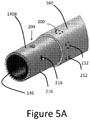
- FIG. 5A illustrates another tip arrangement that can be provided on any of the clearing or cutting devices disclosed herein.
- the embodiment includes a tip 140B that includes a first structure 200 for providing a mechanical interface between the tip 140B and an elongate catheter assembly and a second structure 204 for removing or retaining matter removed from the lesion 17 during the procedure.
- the first structure 200 can include one or a plurality of recesses 212.
- the recesses 212 form a part of an interface disposed between the tissue modifying surface, which can include a ring or ring structure of the tip 140B and one or both of the sleeve 160 and the elongate body 110, which can be disposed within the tip 140B.
- the recesses 212 can be formed around a circumference of the tip 140B, e.g., at equal angularly spaced apart circumferential locations.
- the recesses 212 can be holes disposed entirely through the ring structure of the tip 140B.
- the sleeve 160 and/or the elongate body 110 can interface with the tip 140B by protruding into the recess 212.
- the recesses 212 can be disposed on an inside surface of the sleeve 160 or an outside surface of the elongate body 110 and a lateral protrusion formed on the tip 140B can protrude into the recesses.
- a tip (such as the tip 140, 140A, 140B) can be attached to the mesh 190 at the distal end of the mesh 190.
- the distal end of the tip can be disposed proximally of the distal end of the lining 120 or proximal to the distal end of the distal-most section of the coat material 194.
- the distal end of the tip can be at the line L in Figure 6 .
- This provides a bumper zone 220 distal to the end of the tip 140, 140A, 140B.
- the bumper zone 220 can prevent an unintentional interaction with an un-diseased vessel wall.
- the bumper zone 220 is generally more deformable than the tip 140, 140A, 140B so under a higher force it will either compress axially or radially under the lesion 17 thus not preventing the treatments discussed above.
Description
- This application is directed to devices and systems for treating occlusions, including crossing narrow passages of lumen segments or total occlusions.
- A variety of techniques exist to de-bulk occluded vessel segments. While these techniques have met varying degrees of success, not all patients are successfully treated in this manner. Some patients with peripheral occlusions are left with few options other than amputation of the limb fed by the occluded artery. Such drastic techniques are obviously not available to patients with extensive occlusion of coronary and other critical arteries.
- There are a number of products on the market that are designed specifically for crossing CTOs and these can be categorized as either intraluminal, subintimal or re-entry devices. Intraluminal crossing in theory may reduce the dissection plane of a long occlusive lesion, protect collaterals and keep treatment options open. Subintimal crossing may extend "re-entry" beyond the occluded segment, putting collaterals at risk and limiting treatment options. It may also increase the rates of complications such as perforation and dissection and extend procedure time with resultant increased radiation and contrast exposure. Also below the knee, once a wire has crossed into the adventitia it can be extremely difficult to re-enter the true lumen.
- Certain catheter systems have been developed to cross occlusions in an intraluminal manner. However, these catheter systems have problems. For instance three or more coaxially placed catheter bodies can work in a system to cross a lesion. An inner solid guidewire member can be provided within an outer sheath. An intervening rotatable layer can be advanced over the guidewire from within the outer sheath to gouge or chisel the occlusion mass slowly away. One problem with this structure is that with three or more components, two operators may be needed to handle components of the device.
- Also, with more calcified lesions typical catheter bodies are not well suited to provide access. Generally, catheter bodies are of reduced stiffness toward the distal end thereof to minimize potential for trauma to healthy vascular tissues. However, in order operate on highly calcified lesions, the tip of the device should have greater stiffness.
- Another problem with conventional techniques (i.e., atherectomy-devices) is that debris of atheroma may embolize and may lead to distal embolization including no-reflow phenomenon. In addition, for these devices greater arterial access sheaths are mandatory, which lead to more vascular complications in this normally very ill patients.
- In
US 2008/045986 there is described an atherectomy device for the treatment of occluded body lumens. In particular, the described device relates to the removal of occluding material from blood vessels as well as other body lumens. - In
US 2008/071341 there is described a tip engageable with an elongated sheath member for extracting an implanted elongated structure, such as a cardiac lead, from an obstruction in a body vessel of a patient. The tip includes a tip body having a proximal end, a distal end, and a passageway extending therethrough. The tip body proximal end is engageable with a distal end of the sheath member distal end. The passageway of the tip is aligned with the passageway of the sheath such that the implanted structure is receivable therein. The tip body distal end includes a segment tapering toward a leading edge. A disrupter element, such as a plurality of helices, is disposed along the outer surface of the tip body distal end. The disruptor element is configured for non-cuttingly disrupting the obstruction as the tip is advanced over the implanted structure. - In
WO 2012/058438 there is described an atherectomy catheter having an inner drive shaft which rotates a distal rotary tissue borer with a helical cutting surface which enables the catheter to cut through and cross a CTO. Additionally, the atherectomy catheter has a distal cutting element rotated by an outer drive shaft configured to cut material from the wall of a vessel at a treatment site as the catheter is pushed distally through the treatment site. The atherectomy catheter includes a collection chamber positioned proximally of the cutting element and rotary tissue borer. The atherectomy catheter may include means to direct material cut from the treatment site into the collection chamber, means to break down larger portions of material that may block or clog the collection chamber and means of transporting the material collected from the treatment site to a proximal opening in the atherectomy catheter. - Nonetheless, there exists a need for a flexible, low-profile occlusion crossing catheter that is able to cross a region of vessel stenosis and establish a passageway sufficient to accommodate a balloon catheter or other interventional device. The crossing catheter can be a delivery catheter in some implementations.
- According to the present invention there is provided a clearing device having the features of claim 1 for providing access across an occlusion with a blood vessel or cylindrical body cavity.
- There is also described a system for creating an enlarged passage across an occlusion within a blood vessel or cylindrical body cavity. The system includes the clearing device and at least one of a guidewire and a catheter device. The guidewire has free distal and proximal ends. The guidewire is configured to be advanced relative to an occlusion and has an outer diameter. The catheter device has a flexible body, an implement, and a handle. The elongate body extends between a proximal end and a distal end. The elongate body has a lumen extending therethrough with an inner diameter larger than the outer diameter of the guidewire. The implement has a distal face, a side surface and a proximal end engaged with, e.g., disposed over, the distal end of the elongate body. The distal end of the implement is configured to act upon a portion of the occlusion. The handle is disposed at the proximal end of the elongate body. The system is configured such that distal pressure on the handle urges the implement distally to firmly engage the occlusion. The lumen provides lateral support to the guidewire in some techniques. In other techniques, the catheter itself primarily or solely acts upon the occlusion to enhance a passage therethrough. The system is configured such that rotation of the handle causes the elongate body and the implement to be rotated to enlarge the passage.
- There is also described a catheter for providing access across an occlusion. The catheter has an elongate flexible body and an occlusion implement. The occlusion implement is a device used to clear a path through an occlusion as discussed herein. The elongate flexible body extends between a proximal end and a distal end. The occlusion implement has a rigid distal face and a cylindrical body extending proximally therefrom. The cylindrical body is configured to be juxtaposed relative to a distal portion of the elongate flexible body over an interface. The catheter body is configured to be advanced within the vasculature to an occlusion. In one example or technique, the catheter body is configured to be advanced over a guidewire to the occlusion. In one example or technique, the catheter body is configured to be advanced within the vasculature with an outer surface thereof exposed to the vasculature. In another example or technique, the catheter body is configured to be advanced within a sheath within the vasculature. In such examples or techniques, the outer surface thereof, e.g., including at least the occlusion clearing implement, is exposed adjacent to the occlusion. In another example or technique, the catheter body is configured to be advanced unguided to an occlusion and to enhance access across an occlusion without the presence of a guidewire.
- Preferably the occlusion implement has sufficient crush resistance to enable the energy or motion applied to the catheter to be used to enhance the access across the occlusion rather than to be used in deforming the occlusion implement. A distal tip or occlusion engaging portion should be more crush resistant than a more proximal structure, e.g., than the catheter body. The occlusion implement can be configured to retain a minimum transverse dimension of at least about 90% of its diameter upon application of a crush force of about 103kPa (15psi) whereby deformation of an inner passage thereof is minimal during interaction with an occlusion. The occlusion implement can be configured to retain a minimum transverse dimension of at least about 90% of its diameter upon application of a crush force of about 172kPa (25psi) whereby deformation of an inner passage thereof is minimal during interaction with an occlusion.
- In some variations, the occlusion implement can be configured to retain a minimum transverse dimension, e.g., of at least about 90% of its original or at rest diameter, upon application of a crush force of about 3 Newtons, in some cases as much as 5 Newtons, in some cases up to and exceeding 7 Newtons, and in some
cases 10 Newtons or more. - In some examples, the occlusion implement has a hoop strength greater than 103kPa (15 psi) or in some cases as much as 172kPa (25 psi) to minimize out of round deformation of the implement so that the implement will not bind upon a guidewire or guide catheter during use.
- The catheter can provide other useful functions or can have other useful features. For example, the catheter can be configured to be a conduit for contrast injection in some methods. The injection of contrast can be used to illuminate, e.g., to provide information about the operational state of the catheter, e.g., indicate if it is blocked by abraded matter.
- In some examples, the catheter has variable stiffness, for example has high stiffness at or near its distal end to enhance the occlusion abrading, reducing or eliminating effect. Proximal of the distal end, the flexibility of the catheter can be greater.
- In some techniques, clearing the occlusion can involve removing one or more guidewires and exchanging one guidewire for another guidewire. For example, a flexible wire could be exchanged for a stiff wire or a stiff wire for a flexible wire. It is preferred that such maneuvers do not disturb the position of the distal end of the catheter significantly. Thus, a lubricious coating or material can be provided along the surface forming the guidewire lumen of the catheter. Also, the outer surface can comprise or be coated with a lubricious material to reduce the force needed to advance the catheter exposed within the vasculature or within a guide catheter.
- In various examples below, the shape of cutting features, e.g., teeth, on the distal end of the catheter can be configured to address certain types of occlusive matter. Harder occlusive matter may be more efficiently cleared using teeth or similar structures that deliver a focused force. Less hard occlusive matter may be more efficiently cleared using less aggressive teeth or similar structures, which can act more like a shoe-horn to scoop such material from the vessel lumen.
- In some examples, an approach for addressing the tip or occlusion clearing implement filling with material is provided. The approach may involve exchanging one filled catheter for a clear catheter. In this technique, a catheter is advanced, is filled, and is then removed with a core of material captured therein. Then a second catheter is advanced, filled and removed. This procedure is continued until a path through the occlusion is sufficiently large. Because each removed core may enlarge the bore of or lengthen the passable portion of the occlusion somewhat, second and subsequent catheters can be longer or can have larger internal lumens and/or cutting implements. In other approaches, an aspiration lumen is provided through the catheter. The aspiration lumen can be the same lumen as the guidewire lumen, e.g., a large central lumen. In other examples, separate aspiration lumens can be provided in the wall of the catheter. In this context, aspiration can include removing by negative pressure dislodged portions of the occlusion entirely from the patient's body and from the catheter. Aspiration can also include just taking the dislodged portions up into a passage in the catheter but not necessarily fully out of the patient's body and out of the catheter while the catheter is in the body.
- In some examples, the tip of the catheter is flat, e.g., is perpendicular to the longitudinal axis of the lumen of the catheter. An advantage of this configuration is that it is more deliverable within the patient, e.g., in an exposed approach without a sleeve covering the tip. Angled tips may be used, and when used may be delivered in a protective sheath in some examples or in some techniques involving tortuous vasculature (e.g., in coronary vasculature or in neuro vasculature). Angled tips may be delivered in an exposed state in techniques involving straight or non-tortuous vasculature (e.g., in peripheral vasculature).
- An advantage of the catheter is that the distal tip will generally include or be formed of a material that is highly opaque under X-ray. Thus, as the device is being delivered the clinician can easily see the tip, which can help with its safe delivery to the treatment site, even without the need to inject a contrast medium and, in some techniques, even without a sheath or guidewire. Safety of delivery can also be provided by maintaining the outer diameter of the catheter to a fraction of the unoccluded vessel size. For example, the catheter can be maintained at about one-quarter the size or in some cases as small as one-eighth the size of the vessel diameter. In such examples, the cutting tip preferably has a length about equal to the vessel diameter. This aspect ratio enables the cutting or abrading portion of the catheter to stay centered in and aligned with the longitudinal axis of the vessel. These configurations are particularly suited for non-tortuous, e.g., straight, vessels as are found in the legs and other peripheral vasculature.
- Also described is an exemplary method of treating a patient with total or near total occlusion. In the method a blood vessel is accessed. The access can be by any catheter technique. A guidewire is advanced into the patient to a treatment site. The treatment site has an occlusion that is desired to be cleared or enlarged, for example a total or near total occlusion. A catheter is advanced over the guidewire into apposition with a proximal portion of the occlusion. The catheter has a lumen therethrough and a distal occlusion engaging portion, e.g., an anchor face, at a distal end thereof. The anchor face can be in the form of high friction face or have sharp features to enable the clinician to selectively prevent rotation of a catheter. One or more of [a] compression force or torsion to the guidewire or [b] compression force or torsion is applied to the catheter body to expand or create an access path through the occlusion. An anchor face or other distal occlusion engaging portions can provide stability, like a climber's crampon, to the catheter while a wire is being advanced or rotated therein to help provide access across the occlusion. The expansion of the access path can be by cutting or abrading the occlusion. In some cases, the expansion can be provided or enhanced by a shoe-horn effect.
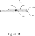
- In another example, a catheter is provided for providing access across an occlusion. The catheter includes an elongate catheter assembly, a lesion clearing implement, and an interface. The elongate catheter assembly extends between a proximal end and a distal end. The lesion clearing implement has a ring structure. The interface is disposed between the ring structure and the elongate catheter assembly. The interface provides a protrusion disposed on one of [a] the elongate catheter assembly and the ring structure and [b] a recess disposed on the other of the elongate catheter assembly and the ring structure. The interface is at least partially in a radial direction such that an axial load can be transmitted across the interface.
- In some examples, the interface is provided such that a protrusion and recess overlap in the axial direction.
- Embodiments of the present invention may be better understood from the following detailed description when read in conjunction with the accompanying drawings. Such embodiments, which are for illustrative purposes only, depict novel and non-obvious aspects of the invention. The drawings include the following figures:
-
Figure 1 illustrates schematically a near total occlusion; -
Figure 1A illustrates a system the can be used to provide access across an occlusion for therapy devices to enhance treatment of an occlusion; -
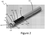
Figure 2 is a perspective view of a first embodiment of a device that can be used in the system ofFigure 1A in providing access across an occlusion for therapy devices; -
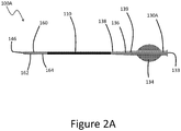
Figure 2A is a plan view of a second embodiment of a device for providing access across an occlusion for therapy devices; -
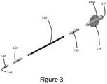
Figure 3 is an exploded perspective view of the second embodiment ofFigure 2A ; -
Figure 4 is a perspective detail view of a distal portion of one variation of an occlusion crossing device; -
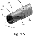
Figure 5 is a perspective detail view of a distal portion of another variation of an occlusion crossing device, which can be incorporated into various embodiments including the first or second embodiments; -
Figure 5A is a perspective detail view of a distal portion of another variation of an occlusion crossing device, which can be incorporated into various embodiments including the first or second embodiments; -
Figure 5B schematically shows one example of a mechanical interface between a tip portion and a catheter assembly. -
Figure 6 is a cut-away view of a distal portion of a catheter body illustrating how the catheter body provides enhanced stiffness in a distal portion; -
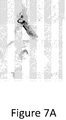
Figure 7A illustrates under fluoroscopic imaging a patient having a chronic total occlusion, which patient is in dire need for a device that can quickly and safely cross the chronic total occlusion; -
Figure 7B illustrates under fluoroscopic imaging a system including a guidewire and an anchorable and/or rotatable crossing device advanced through a patent portion of an artery, toward a total occlusion; -
Figure 7C illustrates under fluoroscopic imaging a treatment device being positioned over the guidewire of the system ofFigure 7B through the total occlusion; -
Figure 7D illustrates under fluoroscopic imaging advancement of the treatment device entirely through the total occlusion to facilitate expansion of a balloon catheter; and -
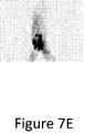
Figure 7E illustrates the same vessel segment illustrated inFigure 7A , where the occlusion has been opened and the flow restored. - The present invention is generally directed to catheter systems for crossing vascular stenosis, such as near total occlusions and components thereof. Exemplary methods of use of such systems and components are also described.
- As used herein, the term "near total occlusion" refers to regions of vascular stenosis that reduce the cross-sectional area of the vessel lumen by >80%, in particular, by >90%, and in some cases by more than 95%. The term "total occlusion" means the entire vessel lumen is fully occupied by atheroma or other occlusive material preventing blood flow through the passage of the lumen.
- As used herein, the term "substantially", when used in reference to a linear dimension (e.g., length, width, thickness, distance, etc.) means within plus or minus one percent (1%) of the value of the referenced linear dimension.
-
Figure 1 is a cartoon representation of a near total occlusion of a blood vessel formed by alesion 17. Theblood vessel 10 has aninterior surface 12, which defines alumen 14. In atherosclerosis, lipid and fibro muscular material accumulate in the vessel wall, forming a lesion that bulges into and occupies or occludes at least a portion of thelumen 14. Advanced-stage atherosclerotic lesions often include regions ofsoft plaque 16 and regions ofatheroma 18. In some cases, theatheroma 18 may be calcified making access by interventional techniques difficult or impossible. - When the
atheroma 18 intrudes into thelumen 14, astenosis 20 is formed that can greatly reduce blood flow through the vessel. Angioplasty is one technique for treating astenosis 20. In balloon angioplasty, a deflated balloon is mounted on an endovascular catheter, and the catheter is pushed along thevessel 10 until the deflated balloon occupies at least a portion of thestenosis 20. Once the deflated balloon is positioned within thestenosis 20, the balloon is inflated, pushing theatheroma 18 back toward the
vessel wall and enlarging thelumen 14 within the region ofstenosis 20. In some cases, an expandable stent is used to restore thelumen 14 within the region ofstenosis 20. - In many cases, a guidewire is pushed ahead of the endovascular catheter to aid catheter travel through the blood vessel. The guidewire is thin and has a smaller profile than the catheter. Often, the catheter has a central lumen that accommodates the guidewire, and the catheter rides along the guidewire. This configuration of catheter is referred to as an "over-the-wire" catheter.
- In some cases, the
stenosis 20 is so narrow that the balloon catheter is unable to follow the guidewire through the stenosis. Rather, the balloon catheter can get hung-up or blocked at the proximal or distal end (depending on the direction of approach) of thestenosis 20. In such a case, angioplasty is precluded because it is not possible to position a deflated balloon within thestenosis 20. In some cases, theatheroma 18 forms a calcified plug that precludes passage of the guidewire through thestenosis 20. -
Figure 1A illustrates anocclusion crossing system 50 that can be used to improve a clinician's ability to pass a balloon catheter or other therapy device across a blockage formed by thelesion 17. Theocclusion crossing system 50 includes asheath 54 and acatheter device 58. Thecatheter device 58 is provided for clearing a passage through thelesion 17 to enlarge the access therethrough, which may involve cutting the occlusion. For this reason, in some passages thecatheter device 58 is referred to as a cutting catheter. Thesheath 54 can be used to enclose and/or guide thecatheter device 58 between a vascular access site and an occlusion. Thesheath 54 thus provides protection for the un-occluded vessel(s) through which thecatheter device 58 is delivered. Theocclusion crossing system 50 can also include aguidewire 62 to help access or cross an occlusion. - The
guidewire 62 can take any suitable form. It can be a long slender wire with no lateral protuberances or it can have one or more lateral extensions. For example a plurality of barriers or shoulders can be provided along a distal length of theguidewire 62 to engage and retain portions of thelesion 17. Theguidewire 62 can have an anchor, such as a helical structure adapted to be advanced rotationally into the lesion to engage and hold it. These are examples of structures that can positively engage and hold thelesion 17. When so engaged, these structures can provide a counter traction for holding the position of the lesion while catheter device 58 (or variant herein) is advanced into the lesion to enhance access
across the lesion. Examples of barriers and anchor are discussed inUS5443443 andUS5047040 . - The
sheath 54 comprises aproximal end 64, adistal end 66, and a lumen extending through anelongate body 65 disposed between theends catheter device 58 as discussed further below. Theproximal end 64 of thesheath 54 is preferably configured to be coupled with other devices. For example, abranched access port 68 can be provided at theproximal end 64. Afirst branch 70 can be provided to couple with a fluid source. Asecond branch 72 can be aligned with the lumen of thesheath 54 to provide in-line access to the lumen of thesheath 54. One or both of thebranches branches proximal end 64 includes amodular coupling 74 that enables the branchedaccess port 68 to be decoupled from theelongate body 65 if access via the branches is not required or for certain phases of procedures where the branches are not needed and might be in the way if not removed from the procedure zone. Thecoupling 74 can includetorque structures 75 on opposite sides thereof. - The
catheter device 58 is configured to be advanced to theocclusion 20 to provide a therapy as discussed herein. Thecatheter device 58 comprises aproximal end 80, adistal end 82, and a lumen extending through anelongate body 84 disposed between theends occlusion 20 to be lodged. Theelongate body 84 has sufficient rigidity for deliverability and for providing cutting or segmenting action at theocclusion 20. For example thebody 84 can be configured to provide 1:1 torque. As discussed below, braids and coils are contemplated as structures providing pushability and flexibility for various applications, including peripheral, coronary and neuro-vascular applications. - The
elongate body 84 has a length sufficient to reach a treatment site such as a peripheral, coronary, or neuro-vascular treatment site. For example, for ipsa-lateral treatment, theelongate body 84 can be between about 40 and about 100 cm, e.g., about 80 cm. For a treatment in the iliac artery, theelongate body 84 can be about 60 cm. For a treatment in the superficial femoral artery (SFA), theelongate body 84 can be between about
140 and 160cm. For a treatment in the coronary arteries, theelongate body 84 can be between about 110 cm and about 140 cm. For neurovascular applications theelongate body 84 can be between about 130 cm and about 180 cm, e.g., about 150 cm. Thesheath 54 can be about 10 cm to about 20 cm shorter than thecatheter device 58. Theelongate body 65 can be 10-20 cm shorter than theelongate body 84. More generally, thesheath 54 orelongate body 65 can be shorter than thecatheter device 58 orelongate body 84 by an amount sufficient to provide a working length. -
Figure 1A shows that the lumen in thebody 84 can receive theguidewire 62 in certain examples and for certain techniques. Theproximal end 80 of thecatheter device 58 is preferably has ahandle 86 that is used to actuate thecatheter 58. Thehandle 86 is configured to transmit a torque. Theproximal end 80 can also include abranched access port 88 or other access device. Afirst branch 90 can be provided to couple with a fluid source F. Asecond branch 92 can be aligned with the lumen of the cuttingcatheter 58 to provide in-line access to the lumen in thebody 84. One or both of thebranches branches branched access port 88 can be detached from thehandle 86 when access via thebranches branched access port 88 is left in place when torqueing thecatheter 58 because thefirst branch 90 provides a higher torque than thehandle 86 in an optional system and technique. - The distal ends 66, 82 can be configured to be incompressible and/or radiopaque. The
distal end 82 can be configured to engage and disrupt theocclusion 20 to enhance access through thestenosis 20. Thedistal end 82 preferably is stiffer than theelongate body 84 at locations proximal of thedistal end 82. Theend 82 includes an occlusion clearing implement 94, which can be one or more teeth, a continuous but abrasive surface for removing matter, a concave scooping structure for separating volumes of the matter from theocclusion 17 or other structures discussed herein. As discussed further below, the implement 94 or thesystem 50 are configured to follow a directed path and not to cause vessel injury in regions not being treated. The implement 94 can be radiopaque to provide visualization of the cuttingcatheter 58 when disposed in the vasculature. - The
sheath 54 is configured to slideably and rotatably receive thecatheter device 58. The inner surface ofelongate body 65 and/or the outer surface ofelongate body 84 can be configured to ease a retracting or extending motion in an axial direction, e.g., along the longitudinal axis of thebody 65 or thebody 84. Either of these surfaces can have a lubricious coating, for example. In one example, the inner surface of thebody 84 includes an expanded polytetrafluoroethylene (ePTFE) or other similar liner. As a result, theend 82 of the cuttingcatheter 58 can be pulled back into theend 66 of thesheath 54 for delivery or pushed out from theend 66 for engagement with theocclusion 20. Theend 66 is configured to minimize out-of-round conditions of thesheath 54. In particular, asupport ring 96 of thebody 65 can be made more rigid than portions of the elongate body proximal of thedistal portion 96 such that theelongate body 84 can freely rotate within thebody 65. For example thesupport ring 96 can include a metal or ceramic cylinder that has hoop strength preventing it from being deformed when urged against an occlusion. The rigidity of thesupport ring 96 provides the advantage that thedistal end 66 will maintain its pre-delivery configuration or will be deformed only by an amount that would not restrict rotation of thebody 84 and thereby theend 82. Thesupport ring 96 can be made of a radiopaque material to enhance visibility of thesheath 54 and thesystem 50. - Exemplary methods of using the
occlusion crossing system 50 or similar systems with any of the alternative components described herein are discussed below -
Figure 2 depicts an embodiment of aclearing device 100. Theclearing device 100 may be used in combination with thecatheter device 58 in theocclusion crossing system 50 discussed above. Theclearing device 100 has ahandle 130 at a proximal end, atip 140 at a distal end, and a flexibleelongate body 110 that is coupled to thehandle 130 and thetip 140. - In some embodiments, the
elongate body 110 is hollow and cylindrical or substantially cylindrical, having aninternal surface 116, acentral lumen 114, aninner diameter 112, and anouter diameter 118. In several embodiments, theinner diameter 112 is about 0.94 mm to about 1.07 mm. In several embodiments, theouter diameter 118 is about 1.12 mm to about 1.37 mm. In some embodiments, thecentral lumen 114 is configured to accommodate a guidewire (not shown). In at least one embodiment, theinner diameter 112 is less than 10% larger than the outer diameter of a guidewire. In other embodiments, a smaller gap on a percentage basis may be provided. For example, some embodiments provide a less than 5% gap between the inner diameter thereof and an outer diameter of a guidewire (e.g., theguidewire 62 ofFigure 1A ). - In other methods and techniques, the guidewire is used to track the
clearing device 100 and specifically thetip 140 to the stenosis. Once in position, the guidewire could be withdrawn and theclearing device 100 can be used to enhance access across the occlusion. If the guidewire is in place theclearing device 100 may rotate about the outer surface of the guidewire independently either exposed in the vessel or in thesheath 54. Thus, in some methods, the guidewire is not required to be in place or to rotate with the system for the device to function. In other methods and for certain applications, a guidewire may not be used even for delivery of the system. For example, if the vessel segment is straight there may not be a need for a guidewire. In such cases, theclearing device 100 preferably is configured to enhance access across an occlusion without support from a guidewire. - One feature that aids in guidance of the
clearing device 100 whether guided by a wire or a guide catheter is the configuration of a rigid distal portion, for example of thetip 140. Thetip 140 can be configured to minimize wandering within a blood vessel. In particular, blood is subject to varying pressures and certain peripheral blood vessels have a relatively high mobility. By making the length of thetip 140 greater than theinner diameter 112 the distal portion of theclearing device 100 tends to remain generally straight in the vessel. In some embodiments, the length of thetip 140 is more than two times the diameter of the tip. In some embodiments, the length of thetip 140 is more than two and one-half times the diameter of the tip. In some embodiments, the length of thetip 140 is more than three times the diameter of the tip. Thetip 140 can be from 1-5 times the diameter of the tip in certain embodiments. - More generally, the
clearing device 100 is not limited to natural body lumens or blood vessels. For example, another application for which the clearing device could be used is for salvaging occluded dialysis grafts. Such an application may benefit from a lower profile clearing device, e.g., one having an outer diameter of about 4-8 mm. - In some embodiments, a lining 120 covers at least a portion of the
inner surface 116. In some embodiments, the lining 120 is made of a material that enhances the lubricity of theinner surface 116. In at least one embodiment, the lining 120 is made from ePTFE. The lining 120 or other lubricious structure or coating such as silicone or other surface modification facilitates sliding of theelongate body 110 over a guidewire in a manner that reduces or minimizes forces that would tend to change the tracking force, the torque force, and the position of the distal portion, such as a tip of theclearing device 100. As discussed below, in one mode the tip of theclearing device 100 is rotated about the guidewire to provide an abrading or gentle cutting action. Such action could be prevented if the distal portion, e.g., the tip becomes out of round due to such forces. - In several embodiments, the outer surface of the
clearing device 100 is coated with a lubricious coating or structure to reduce friction with the vessel wall during tracking, torqueing, and crossing of the stenosis. Examples of such structures include a layer of Teflon, silicon, or a hydrophilic coating. A lubricious sleeve could be used, which sleeve can be moveable relative to, e.g., configured to be withdrawn from theclearing device 100. - The
clearing device 100 has atip 140 that is coupled to adistal end 152 of theelongate body 110. Aproximal end 154 of thetip 140 is disposed over thedistal end 152 of theelongate body 110. In several embodiments, the cutting tip is attached to a braided skeleton of the catheter body prior to coating the entire structure with an extruded polymer, after which the tip can be subsequently exposed. Other reinforced catheter designs tend to store energy in the reinforcement. The result is something like winding a spring rather than providing a one-to-one rotation of the distal end upon rotation of the proximal end. In the catheters described herein the braided skeleton is preferably formed to reduce storing energy in the catheter body and to maintain as close as possible a one-to-one rotation to enhance the cutting work at the distal end for the rotation at the proximal end.Figure 6 shows amesh material 190 to which the tip
could be welded or otherwise coupled, for example. In other embodiments, the cutting tip can be attached to the catheter with an adhesive. Variations provide multiple layers of adhesive and layers that can be applied or heat-shrunk over inner layers of theclearing device 100. In some cases, as described herein a recess and/or protrusion provide a strong mechanical interface alone or in combination with other attachment structures. - The
clearing device 100 has ahandle 130 coupled to theproximal end 132 of theelongate body 110. In some embodiments, thehandle 130 is configured to apply torque to theelongate body 110 as a user rotates thehandle 130. In at least one embodiment, theclearing device 100 is configured so that thehandle 130 applies approximately a 1:1 torque ratio to theelongate body 110, causing thetip 140 to rotate substantially in unison with thehandle 130. In some embodiments, thehandle 130 is made of polymer. In at least one embodiment, thehandle 130 is made of polycarbonate. -
Figure 2A depicts an embodiment of aclearing device 100A that is similar to theclearing device 100 except as set forth differently below. Theclearing device 100A can be used with one or more components of thesystem 50. In this embodiment, ahandle 130A is provided that includes at least onerib 134 that enhances a user's ability to apply torque by finger pressure to theelongate body 110. In the illustrated embodiment, thehandle 130A has two ribs that are disposed on opposite sides of the body of thehandle 130A. This structure enables a user to apply pressure by a thumb and index finger of a single hand to rotate theclearing device 100A. This provides for easy abrading or cutting action, with the procedure being performed with just one or two hands. For instance, as discussed more below, this approach enables a user to hold a guidewire in one hand and theclearing device 100A in the other hand and to provide rotation of the clearing device over the guidewire when so held. - In another technique, by altering the tension or compression on the guidewire the user can direct the leading edge of the
clearing device clearing device 100 can be altered. A plurality of wires of different bending stiffness could be used to vary the bending stiffness under compression. In one case, two or three wires are provided which will be relatively stiff and could cause some enlargement of the occluded lumen. If operation of theclearing device 100 is to commence, one or more of the wires can be removed. For
instance a first wire can be removed so that the remaining wires will bow under compression. A tangent to the bent wire(s) that remain will define the trajectory of theclearing device clearing device clearing devices 100 could be used to enlarge the lumen slightly more for each device. - In some embodiments, the
handle 130A is joined to theelongate body 110, which is of a different configuration, e.g., a different material or physical structure. In such arrangements, a strain relief structure can be provided between thehandle 130A and theelongate body 110 to minimize kinking or other failure modes. One example of a strain relief structure includes acollar 136 that couples handle 130A to theelongate body 110. In at least one embodiment, thecollar 136 is bonded to thehandle 130A using an adhesive. In some embodiments, thecollar 136 is tapered such that adistal end 138 of thecollar 136 has an outer diameter that is smaller than the outer diameter of aproximal end 139 of thecollar 136. In several embodiments, thecollar 136 is made of polymer. In at least one embodiment, thecollar 136 is made of nylon. In at least one embodiment, thecollar 136 is made of polyether block amide (PEBA). Other functions of the strain relief include one or more of the minimization of kinking during general handling, tracking and torqueing of the catheter, facilitating the bonding of a larger diameter handle to the smaller diameter catheter body, providing a surface for the printing of catheter specifications or color to denote the configuration of the catheter. - In several embodiments, the
clearing device 100 comprises asleeve 160 that surrounds at least a portion of theelongate body 110. In some embodiments, thesleeve 160 strengthens the junction of thetip 140 to theelongate body 110. In several embodiments, thesleeve 160 minimizes abrupt diameter changes that may result during assembly of thetip 140 to theelongate body 110. In some embodiments, thesleeve 160 surrounds the distal portion of theelongate body 110. In at least one embodiment, thesleeve 160 surrounds the proximal portion of thetip 140 and the distal portion of theelongate body 110. In some embodiments, adistal portion 162 of thesleeve 160 has an outer diameter that is larger than the outer diameter of aproximal portion 164 of thesleeve 160. In at least one embodiment, thesleeve 160 is made of shrink tubing material. Other functions of or modes of operation of the sleeve 160 (e.g., shrink tubing 160) include providing any or all of the following: - lubricity - the outer surface may be made of a material that is more slippery or made to be more slippery than the catheter body thus facilitating tracking and torqueing the catheter;
- support - the sleeve may be configured to increase the longitudinal stiffness of the distal portion of the catheter, resulting in the cutting tip being guided in a straight line; and/or
- protection - the sleeve covers the trailing edge of the cutting tip and protects it from being dislodged during tracking and torqueing.
- Although illustrated as a separate layer that is applied to the
elongate body 110, thesleeve 160 could be configured as a coating or could include a coating disposed over it. -
Figures 4 and5 depict illustrative examples of thetip 140. As discussed below, thetip 140 interacts with the lesion tissue and is configured to remove or displace lesion tissue. In several examples, thetip 140 is configured to remove lesion tissue through different modes of operation including cutting, tearing, shaving, or abrading the lesion tissue. Thetip 140 may be configured to use one, or more than one, method of removing lesion tissue. In several examples, thetip 140 provides lateral support to the guidewire as the guidewire is advanced through a stenosis. In some examples, thetip 140 can prevent the guidewire from buckling as the guidewire is advanced through an occlusion or a near total occlusion. In providing this function, thetip 140 can be configured with a bore having a diameter that is close to that of the guidewire, e.g., within about 10% of the diameter of the guidewire. The gap between the guidewire and theclearing device 100 should be large enough to keep resistance to relative movement (advancement and/or rotation) between these components to an acceptable level for tracking and twisting. In addition, theclearing device 100 may be used as an exchange device for changing guidewires or other interventional devices without losing position or access to the target lesion. The lumen in theclearing device 100 can be used for drug delivery and contrast injection as needed. - The
tip 140 has adistal face 142, aside surface 144, and adistal opening 146. In the example of thetip 140 shown inFigure 4 , thedistal face 142 of thetip 140 is disposed generally at a plane extending transverse to the longitudinal axis of thetip 140. Theface 142 can also be beveled, such that it is rounded in a proximal direction from such a plane, e.g., toward an outer surface of thetip 140. This arrangement is advantageous in that a longitudinal force along the axis of theclearing device 100 will produce a generally straight trajectory of thetip 140 as it advances. Thedistal face 142 can be disposed on a plane at an acute angle to the longitudinal axis in certain examples, but disposing thedistal face 142 on a transverse plane results in less deflection of the tip upon advancement or rotation. - In some examples the
tip 140 can be beveled and serrated. An example of a serrated tip provides a plurality of sharp edges on thesurface 144 disposed around the circumference of thetip 140. The sharp edges can be elongated and disposed on theside surface 144. The edges can be axial edges. The edges can be spiral edges. In some examples, the sharp edges can be configured for removing material from the clearing zone disposed around thedistal face 142. In some examples, teeth or other cutting structures can be disposed on the inside of the lumen extending proximally from thedistal opening 146. Cutting structures disposed on theside surface 144 can have an arcuate configuration facing the direction of the cut. For example, the cutting surface can have an angle of attack facing the direction of motion of the clearing device. The cutting surface can be positioned to maximally cut upon rotation of theclearing device 100 in some examples. The cutting surface can be positioned to maximally cut upon advancement of theclearing device 100 in some examples. In some examples, thedistal face 142 is blunt (not shown). In at least one example, thedistal face 142 is abrasive. In the example of thetip 140A shown inFigure 5 , thedistal face 142A has a plurality of cuttingteeth 170. Theface 142A can also be considered to be disposed on a transverse plane, for example, if the distal aspects or proximal aspects of theteeth 170 are disposed at the same plane disposed transverse to the axis of thetip 140A. In some examples, the cuttingteeth 170 are configured to hold the lesion tissue fixed relative to thetip 140A, allowing theclearing device 100 to tear lesion tissue away from a vessel wall. In some examples, the cuttingteeth 170 are configured to slice through the lesion tissue, allowing the clearing
device 100 to remove lesion tissue in a manner that minimizes twisting stress on the vessel wall. - In several examples, the
side surface 144 oftip 140 includes an element for moving displaced or separated abraded matter from the working zone of theclearing device 100. For example, in one implementation at least oneflute 180 serves to debulk the lesion as thetip 140 rotates within thestenosis 20. In some techniques, aspiration is provided through a main (e.g., central) lumen of theclearing device 100. In some approaches, if a guidewire is present, aspiration through the main lumen can be enhanced by removing the guidewire. - In some examples, the
flute 180 includes a hole that passes through thetip 140. In at least one example, theflute 180 communicates with a lumen, e.g., a dedicated aspiration lumen (not shown) or thecentral lumen 114 of theelongate body 110. If the abraded matter is to be aspirated out of theclearing device inner surface 116 of theelongate body 110 and the outer surface of the guidewire should remain as debris-free as possible to reduce the chance of these surfaces becoming seized. In other examples, a greater gap is provided between the inside surface of theelongate body 110 and a guidewire positioned therein and abraded or separated matter from the occlusion can be aspirated or sequestered in the main lumen. In at least one example, theflute 180 is a circular hole having a diameter of 6.6 mm. - Other uses for the
flutes 180 are to confirm the status of theclearing device 100. For example, an imaging agent can be delivered through a lumen in fluid communication with the flutes. The pattern of the images indicates the status of the clearing device. In one instance, the imaging agent may not emerge from theclearing device 100. The clinician can then know that theclearing device 100 is occluded and could be removed and either cleared or replaced with a second clearing device. In another instance, the imaging agent can indicate whether the occlusion of the vessel is sufficiently enlarged for other treatment. In another instance, the imaging agent may indicate that a different mode of use of theclearing device 100 should be used. For example, if one side of theclearing device 100 is occluded a second side of the device could be rotated into position to further clear the lumen. - In some examples, apertures similar to the
flutes 180 can be provided through thetip 140A to provide for securement to other parts of the clearing device. For example, thetip 140A can be configured as a metal cylinder to be joined to an elongate polymeric catheter body. To secure the cylinder, holes in the cylinder can be configured and positioned to have portions of the catheter flow or extend into the holes. In one technique a polymeric body of theclearing device 100 disposed on the inside of the cylinder is formed such that a portion thereof protrudes radially outwardly into the holes. In one technique a polymeric body of theclearing device 100 disposed on the outside of the cylinder is formed such that a portion thereof protrudes radially inwardly into the holes.Figure 5A shows an example where holes are disposed beneath thesleeve 160. The sleeve is applied to a portion of theside surface 144 of thetip 140A such that the sleeve extends into the holes. This provides for securement of the cylinder to prevent it from slipping off theelongate body 110 or from being displaced proximally which would interfere with the clearing function. - The
elongate body 110 proximal of thetip 140 must be flexible to enable theclearing device 100 to travel through a tortuous vasculature for certain applications, e.g., for coronary or neurovascular procedures. At the same time, theelongate body 110 must be stiff to transmit compressive and torsional forces to thetip 140. In several examples, theelongate body 110 is made of polymer. In some examples, theelongate body 110 is made of a polymeric material selected from the group consisting of polyimide, and PEBA. In some examples, theelongate body 110 is made of one material embedded in another material. In an example depicted inFigure 6 , theelongate body 110 is made of amesh material 190 embedded in acoat material 194. In at least one example, themesh material 190 includes 304-stainless steel flat wire braid. In at least one example, thecoat material 194 is made of a polymer, such as polyimide and/or PEBA. In some examples, multiple layer and multiple polymers may be employed. In addition, in several examples the elongate body can be fashioned from a material or composite structure at the proximal end to provide more push such as a hypotube and be attached to a material of softer stiffness to facilitate tracking and delivery of the cutting tip. - In several procedures, the
clearing device 100 is used in conjunction with a guidewire (not shown). In many procedures, a guidewire is advanced endovascularly until the distal end of the guidewire reaches a stenosis targeted for
angioplasty. In some procedures, theclearing device 100 is mounted onto a guidewire by feeding the proximal end of the guidewire into thedistal opening 146 of thetip 140. The guidewire is then passed through thecentral lumen 114 of thecapture device 110, and drawn out of theproximal opening 133 of thehandle 130. Thetip 140 is advanced along the guidewire until thedistal face 142 of thetip 140 encounters thelesion 17. As discussed elsewhere herein, close clearance between thelumen 114 and a guidewire helps to reduce the crossing profile. In some procedures and in some techniques, having a close clearing also helps in bracing the guidewire. Bracing is not required for various procedures and techniques. In some cases, a guidewire is not needed in any aspect of the exemplary method. - In some procedures, the
tip 140 is used to gently abrade thelesion 17. Once thedistal face 142 makes contact with thelesion 17, a user applies torque to thehandle 130, causing thehandle 130 to rotate about the guidewire. Theelongate body 110 transmits the torque to thetip 140, causing thedistal face 142 of thetip 140 to slide over the surface of thelesion 17. In many procedures, a user rotates thehandle 130 in alternating clockwise and counterclockwise directions. In some procedures, thehandle 130 is rotated in only one direction. In some procedures, a user applies compressive forces by pushing thehandle 130 in the distal direction. In some procedures, a user applies simultaneously compressive and torsional forces by pushing thehandle 130 in the distal direction while rotatinghandle 130 about the guidewire. - In several examples, the
tip 140 is configured to resist deformation. In some examples, thetip 140 is made of an alloy possessing high strength properties. In at least one example, thetip 140 is made of seamless drawn tubing of L-605 composition. In several examples, thetip 140 defines a circular lumen. In at least one example, thetip 140 has an inner diameter of 1.25 mm and a circularity of less than 0.0050 mm. In at least one example, thetip 140 is a hollow cylinder with an outer diameter of 1.45 mm, a wall thickness of 0.2 mm, and a length of 4.5 mm. As noted above, configuring the tip to avoid being deformed out of round provides assurance that theclearing device clearing device clearing device 100 can provide a bracing effect to the guidewire. This bracing effect enables the guidewire to be advanced distally out of the abrading device in a mode of
operation where the guidewire is urged forward across the lesion. In order to provide this bracing effect while still maintaining theclearing device 100 rotatable over the guidewire, out of round deformation of the inner diameter should be reduced, minimized or eliminated. -
Figure 5A illustrates another tip arrangement that can be provided on any of the clearing or cutting devices disclosed herein. The embodiment includes atip 140B that includes afirst structure 200 for providing a mechanical interface between thetip 140B and an elongate catheter assembly and asecond structure 204 for removing or retaining matter removed from thelesion 17 during the procedure. Thefirst structure 200 can include one or a plurality ofrecesses 212. Therecesses 212 form a part of an interface disposed between the tissue modifying surface, which can include a ring or ring structure of thetip 140B and one or both of thesleeve 160 and theelongate body 110, which can be disposed within thetip 140B. Therecesses 212 can be formed around a circumference of thetip 140B, e.g., at equal angularly spaced apart circumferential locations. Therecesses 212 can be holes disposed entirely through the ring structure of thetip 140B. Thesleeve 160 and/or theelongate body 110 can interface with thetip 140B by protruding into therecess 212. In other arrangements, therecesses 212 can be disposed on an inside surface of thesleeve 160 or an outside surface of theelongate body 110 and a lateral protrusion formed on thetip 140B can protrude into the recesses. The interface between therecesses 212 and the elongate catheter assembly can be disposed at least partially in a radial direction. As such, an axial load can be transmitted across the interface such that a pushing, pulling or rotational force is directly transmitted from the proximal end to thetip 140B. Also, the interface formed in and by therecesses 212 provides supplemental securement to thetip 140B such that it will not detach from theelongate body 110. - The
second structure 204 can include a plurality ofapertures 216 disposed about the circumference of thetip 140B. The holes provide for thetip 140B to take in matter that is liberated from thelesion 17. As discussed above, theapertures 216 can be blind end holes or can extend entirely through thetip 140B and be in fluid communication with a lumen for aspiration or retention of the matter. Thesecond structure 204 can be arranged at one axial position or can be an array of holes disposed along a length of thetip 140B. - The
second structure 204 can be in communication with a source of fluid, e.g., through thebranch 90, such that fluid can be injected through an aperture or through an array of apertures. The fluid can be a medication or can act as a lubricant to facilitate motion. The fluid can be a contrast medium such that the outflow through the apertures of thesecond structure 204 can indicate the degree of fill of the interior of theclearing device 100. - In various arrangements, the
second structure 204 can include apertures of different types such that distal-most apertures may extend partly through the wall of thetip portion 140B while apertures proximal thereof may extend entirely through the wall to provide fluid communication between an outside of theclearing device 100 and a lumen therein. That way more distal apertures can fill without obstructing the lumen. Once the distal-most apertures are filled, the more proximal holes will become obstructed and prevent contrast from flowing out of thedevice 100 indicating the device is full or nearly full. - A further example is illustrated in connection with
Figure 6 . In particular, a tip (such as thetip mesh 190 at the distal end of themesh 190. The distal end of the tip can be disposed proximally of the distal end of the lining 120 or proximal to the distal end of the distal-most section of thecoat material 194. For example, the distal end of the tip can be at the line L inFigure 6 . This provides abumper zone 220 distal to the end of thetip bumper zone 220 can prevent an unintentional interaction with an un-diseased vessel wall. Thebumper zone 220 is generally more deformable than thetip lesion 17 thus not preventing the treatments discussed above. -
Figure 5B shows a partial cross-section of one wall of acatheter device structure 200 for providing a mechanical interface. An interface is disposed between the ring structure of thetip 140B and the elongate catheter assembly. The interface I provides a protrusion of thelayer 160 into therecesses 212 as shown. In an alternative arrangement, thelayer 110 can extend radially outwardly into therecess 212. The interface is at least partially in a radial direction in that a portion of thelayer 160 is deformed intorecess 212. An axial load can be transmitted across the interface I in the direction of the arrow A. In some arrangements, the interface is provided such that a protrusion and recess overlap in the axial direction. The distal aspect of theaperture 212 can be just distal of
(axially in front of) a portion of thelayer 160. The proximal aspect of theaperture 212 can be just proximal of (axially behind a portion of thelayer 160. - In some examples, radial stiffness and resistance to deformation should be minimal at least in an occlusion clearing portion. A braid, such as the
mesh material 190, can be used to reduce or eliminate deformation of the inner diameter. - In at least one example the tip has an oval or non-round outer profile or is disposed radially or laterally away from an axis of rotation of the catheter assembly. Such an arrangement provides that when the clearing device is rotated about the guidewire it creates a circular lumen larger with a cross-sectional area greater than the cross-sectional area of the crossing device. In one example, an oval or other non-round outer profile may be best for softer material. A round outer profile may be better to provide a more focused force to clear harder materials.
- Another advantage of a structure maintaining inner diameter stability is that the crossing profile and clearance will be more constant and more predictable. In contrast, if the tip compresses and the tip deforms, the profile of the tip may be reduced, which will reduce effectiveness in clearing the lumen. If the inner diameter is collapsed, the clearance may be reduced or eliminated. Reducing or eliminating the clearance may result in cutting off the ability to remove severed matter from the
clearing device 100. This may result in blockage of the device and the need to replace theclearing device 100. - An actual use of a clearing device similar to the
clearing device 100 and thesystem 50 is illustrated byFigures 7A-7F .Figure 7A illustrates under fluoroscopic imaging a patient having a chronic total occlusion. The dark region shows that contrast media that has been injected is trapped upstream of the occlusion.Figure 7B illustrates the device under fluoroscopic imaging. Theclearing device 100 is disposed over a guidewire. The clearing device is positioned to be (and is after the point in time recorded inFigure 7B ) advanced through the occlusion.Figure 7C illustrates under fluoroscopic imaging a balloon catheter disposed over the guidewire and across the occlusion.Figure 7D illustrates under fluoroscopic imaging the balloon expanded at and on both sides of the occlusion. The arrows point to a narrowing of the balloon at the site of the occlusion showing that the remains of the occlusion are more rigid than the balloon.Figure 7E illustrates the same vessel segment of illustrated inFigure 7A , where the occlusion has been opened and the flow restored. - A 54-year-old male presented Stage IIb peripheral artery disease (PAD) arising from restenosis of a stent placed in the right common iliac artery four years earlier. A 0.889mm (0.035-inch) diameter PTFE endovascular guidewire was inserted into the patient and advanced across the region of stenosis. A balloon catheter was then mounted onto the guidewire in an over-the-wire (OTW) configuration and advanced to the region of stenosis. The balloon catheter was unable to cross the target stenosis. The balloon catheter was withdrawn from the patient, and an embodiment of the
clearing device 100 was mounted onto the guidewire in an OTW configuration. In this and the following examples, embodiments of theclearing device 100 were used. The embodiment of theclearing device 100 used to treat this patient had a 0.889mm (0.035 inch) inner diameter and a leading edge outer diameter of 1.803mm (0.071 inch). As discussed above, the serrated tip was used to advance the catheter in resistant lesions by abrading or cutting through the inner luminal edges of the vessel stenosis in much the same way that a saw is used to cut through a piece of wood. While the blunt or beveled tip is used more like a shoe horn, it may also have to some degree abrading abilities. - The
tip 140 used to treat this patient had adistal surface 142 that was blunt and abrasive. Theclearing device 100 was advanced along the guidewire until thedistal surface 142 of thetip 140 made contact with the lesion tissue. Thedistal surface 142 of thetip 140 gently abraded the lesion tissue. Gentle abrasion was achieved by pushing thehandle 130 in the distal direction and, at the same time, rotating thehandle 130 about the guidewire. Thehandle 130 was rotated in both directions during the abrading procedure. - As the lesion tissue was abraded, the
clearing device 100 was advanced along the guidewire until thetip 140 had crossed the region of stenosis. After thetip 140 had crossed the region of stenosis, theclearing device 100 was withdrawn from the patient, and a balloon catheter was re-mounted on the guidewire in an OTW configuration. The balloon catheter was advanced along the guidewire to reach the target stenosis. The balloon catheter was now able to enter the region of stenosis because theclearing device 100 had abraded the target lesion and enlarged the stenosis, allowing the stenosis to accommodate the profile of the balloon catheter. Once the balloon catheter was positioned within the lumen of the target stenosis, the balloon was inflated to further enlarge the stenosis. After balloon angioplasty, the balloon catheter was removed from the patient. Radiography confirmed blood flow was restored in the targeted vessel. - A 70-year-old male presented Stage IIb peripheral artery disease (PAD) arising from occlusion of the superficial femoral artery. Radiographic imaging indicated the occlusion affected a length of >25 cm of artery, with the patient having 95% truncus tibiofibularis stenosis. A 0.889mm (0.035-inch) diameter endovascular guidewire was inserted into the patient and advanced across the region of stenosis. A balloon catheter was mounted onto the guidewire in an over-the-wire (OTW) configuration and advanced to the region of stenosis. The balloon catheter was unable to cross the target stenosis. The balloon catheter was withdrawn from the patient, and an embodiment of the
clearing device 100 was mounted onto the guidewire in an OTW configuration. The embodiment of theclearing device 100 used to treat this patient had a 0.889mm (0.035 inch) inner diameter and a leading edge outer diameter of 1.803mm (0.071 inch). - The
clearing device 100 was advanced along the guidewire until thedistal surface 142 of thetip 140 made contact with the lesion tissue. Thedistal surface 142 of thetip 140 gently abraded the lesion tissue. Gentle abrasion was achieved by pushing thehandle 130 in the distal direction and, at the same time, rotating thehandle 130 about the guidewire. Thehandle 130 was rotated in both directions during the abrading procedure. Applying gentle pressure on thehandle 130 ensured thedistal surface 142 of thetip 140 was abrading the lesion by moving over the lesion surface. If pressure is applied too strongly to thehandle 130 the lesion tissue may merely twist in unison with thedistal surface 142 of thetip 140, making the abrading procedure ineffective. As the lesion tissue was abraded, theclearing device 100 was advanced along the guidewire until thetip 140 had crossed the region of stenosis. After thetip 140 had crossed the region of stenosis, theclearing device 100 was
withdrawn from the patient and angioplasty was performed. Radiography confirmed blood flow was restored in the treated vessel. - An 86-year-old male presented Stage IIb peripheral artery disease (PAD) arising from occlusion of the superficial femoral artery. Radiographic imaging indicated the occlusion affected a length of <6 cm of artery. A 0.889mm (0.035-inch) diameter endovascular guidewire was inserted into the patient and advanced across the region of stenosis. A balloon catheter was mounted onto the guidewire in an over-the-wire (OTW) configuration and advanced to the region of stenosis. The balloon catheter was unable to cross the target stenosis. The balloon catheter was withdrawn from the patient, and an embodiment of the
clearing device 100 was mounted onto the guidewire in an OTW configuration. The embodiment of theclearing device 100 used to treat this patient had a 0.889mm (0.035 inch) inner diameter and a leading edge outer diameter of 1.803mm (0.071 inch). - The
tip 140 of theclearing device 100 was moved to the target lesion by advancing thehandle 130 distally along the guidewire. Once thedistal face 142 of thetip 140 was in contact with the target lesion, thehandle 130 of theclearing device 100 was gently pushed in the distal direction and rotated back-and-forth about the guidewire, causing thedistal face 142 to gently abrade the target lesion. This method of lesion abrasion was continued until thetip 140 of theclearing device 100 had crossed the region of stenosis. Once thetip 140 crossed the lesion, theclearing device 100 was withdrawn from the patient by pulling thehandle 130 in a proximal direction until theclearing device 100 was removed from the guidewire. Next, a balloon catheter was mounted onto the guidewire for use in balloon angioplasty. The balloon catheter was mounted on the guidewire in an OTW configuration and advanced along the guidewire to reach the target stenosis. The balloon catheter was now able to enter the region of stenosis because theclearing device 100 had abraded the target lesion and enlarged the stenosis, allowing the stenosis to accommodate the profile of the balloon catheter. Once the balloon catheter was positioned within the lumen of the target stenosis, the balloon was inflated to further enlarge the stenosis. - After balloon angioplasty, the balloon catheter was removed from the patient, and a delivery catheter carrying an expandable stent was mounted onto the guidewire in an OTW configuration. The delivery catheter was advanced along the guidewire until the DES was within the lumen of the target stenosis. The stent was then deployed to maintain the enlarged lumen and restore blood flow to the previously occluded vessel.
- A 72-year-old male presented Stage IV peripheral artery disease (PAD) arising from calcified below-the-knee (BTK) 99% truncus tibiofibiolaris stenosis. After a successful wire-crossing of the stenosis by a 0.356mm (0.014-inch) diameter guidewire, a 1.2 mm outer diameter over-the-wire balloon catheter was advanced along the guidewire using a 1.5 mm diameter push catheter. The balloon catheter was unable to cross the stenosis. The balloon catheter was withdrawn from the patient and an embodiment of the
clearing device 100 was mounted onto the guidewire in an OTW configuration. Thetip 140 used for this example had a 0.457mm (0.018 inch) inner diameter and a leading edge outer diameter of 1.600mm (0.063 inch). Thehandle 130 was moved distally along the guidewire to advance thetip 140 to the target lesion. Once thedistal face 142 of thetip 140 was in contact with the target lesion, thehandle 130 of theclearing device 100 was gently pushed in the distal direction and rotated back-and-forth about the guidewire to cause thedistal face 142 to gently abrade the target lesion. - This method of lesion abrasion was continued until the
tip 140 of theclearing device 100 had crossed completely the region of stenosis. Once thetip 140 crossed the lesion, theclearing device 100 was withdrawn from the patient by pulling thehandle 130 in a proximal direction until theclearing device 100 was removed from the guidewire. Next, a blade angioplasty catheter was again mounted onto the guide wire in an OTW configuration. The blade angioplasty catheter was advanced along the guidewire. The blade angioplasty catheter was now able to enter the region of stenosis because theclearing device 100 had abraded the target lesion and enlarged the stenosis, allowing the stenosis to accommodate the profile of the blade angioplasty catheter. The blade angioplasty catheter was used to further enlarge the stenosis. After blade angioplasty, the blade angioplasty catheter was removed from the patient, and a delivery catheter carrying an expandable drug-eluting stent (DES) was mounted onto the guidewire in an OTW configuration. The delivery catheter was advanced along the guidewire until the DES was within the lumen of the target
lesion. The DES was then deployed to maintain the enlarged lumen and restore blood flow to the previously occluded vessel. - The above presents a description of modes contemplated of carrying out the present invention, and of the manner and process of making and using it, in such full, clear, concise, and exact terms as to enable any person skilled in the art to which it pertains to make and use this invention. This invention is, however, susceptible to modifications and alternate constructions from that discussed above which are fully equivalent. Consequently, it is not the intention to limit this invention to the particular embodiments disclosed. On the contrary, the intention is to cover modifications and alternate constructions coming within the scope of the invention as defined by the following claims, which particularly point out and distinctly claim the subject matter of the invention.
Claims (15)
- A clearing device (100) for providing access across an occlusion within a blood vessel or cylindrical body cavity, comprising:a flexible elongate body (110) extending between a proximal end (132) and a distal end (152), the elongate body (110) having a lumen (114) extending therethrough, the lumen (114) having an inner diameter (112);an implement (140) configured as a hollow cylinder having a rigid distal face (142) and a cylindrical body extending proximally therefrom and defining a ring structure having a side surface (144) with at least one opening (180) extending inwardly from the side surface (144) and a proximal end (154) engaged with the distal end (152) of the elongate body (110), the proximal end (154) of the implement (140) being disposed over the distal end (152) of the elongate body (110) and the distal face (142) of the implement (140) being configured to act upon a portion of the occlusion; anda handle (130) disposed at the proximal end (132) of the elongate body (110);wherein the clearing device (100) is configured such that distal pressure on the handle (130) urges the implement (140) distally to firmly engage the occlusion; andactuating the handle (130) causes the elongate body (110) and the implement (140) to be actuated to enlarge a passage through the occlusion.
- The clearing device (100) of claim 1, wherein the distal face (142) of the implement (140) comprises a cutting blade.
- The clearing device (100) of claim 1, wherein the distal face (142) of the implement (140) is blunt.
- The clearing device (100) of claim 1 or claim 3, wherein the distal face (142) is abrasive.
- The clearing device (100) of any preceding claim, wherein the at least one opening (180) comprises at least one flute for clearing an amount of abraded matter.
- The clearing device (100) of claim 5, wherein the at least one flute (180) extends radially inwardly and is in fluid communication with an aspiration lumen.
- The clearing device (100) of any preceding claim, further comprising a sleeve (160) that surrounds a proximal portion of the implement (140) and a distal portion of the elongate body (110).
- The clearing device (100) of any preceding claim, wherein the distal face (142) is disposed generally in a plane extending transverse to a longitudinal axis of the implement (140).
- The clearing device (100) of any of claims 1 to 7, wherein the distal face (142) is beveled, such that it is rounded in a proximal direction.
- The clearing device (100) of any preceding claim, further comprising a mechanical interface (I) between the implement (140) and the elongate body (110), the mechanical interface (I) comprising a recess (212) in one of the implement (140) and the elongate body (110) and a protrusion on the other, the protrusion extending at least partially in a radial direction and into the recess (212).
- The clearing device (100) of any preceding claim further comprising a flexible bumper zone (220) formed by a distal end of the implement (140) being disposed proximally of a distal end of a lining (120) or proximal to a distal end of a distal-most section of a coat material (194).
- The clearing device (100) of claim 11, wherein the bumper zone (220) is generally more deformable than the implement (140).
- A system (50) for crossing an occlusion within a blood vessel or cylindrical body cavity, the system (50) comprising:a clearing device (100) in accordance with any preceding claim; anda sheath (54) configured to slideably receive and to be disposed circumferentially about the clearing device (100) such that the clearing device (100) can be delivered to a lesion without being exposed to the vasculature.
- A system (50) for crossing an occlusion within a blood vessel or cylindrical body cavity, the system (50) comprising:a clearing device (100) in accordance with any of claims 1 to 12; anda guidewire (62) having free distal and proximal ends and being configured to be advanced relative to an occlusion, the guidewire (62) having an outer diameter smaller than the inner diameter (112) of the lumen (114).
- The system (50) of claim 14, wherein an inner surface (116) of the elongate body (110) is provided with a lining (120) or other lubricious structure, coating or surface modification that facilitates sliding of the elongate body (110) over the guidewire (62).
Applications Claiming Priority (2)
| Application Number | Priority Date | Filing Date | Title |
|---|---|---|---|
| US201361879384P | 2013-09-18 | 2013-09-18 | |
| PCT/US2014/056162 WO2015042190A2 (en) | 2013-09-18 | 2014-09-17 | Systems and methods for crossing and treating an occlusion |
Publications (3)
| Publication Number | Publication Date |
|---|---|
| EP3035876A2 EP3035876A2 (en) | 2016-06-29 |
| EP3035876A4 EP3035876A4 (en) | 2017-03-22 |
| EP3035876B1 true EP3035876B1 (en) | 2018-11-14 |
Family
ID=52689592
Family Applications (1)
| Application Number | Title | Priority Date | Filing Date |
|---|---|---|---|
| EP14845424.2A Active EP3035876B1 (en) | 2013-09-18 | 2014-09-17 | Device and system for crossing and treating an occlusion |
Country Status (5)
| Country | Link |
|---|---|
| US (5) | US9622762B2 (en) |
| EP (1) | EP3035876B1 (en) |
| JP (3) | JP2016533861A (en) |
| CN (1) | CN105873530B (en) |
| WO (1) | WO2015042190A2 (en) |
Families Citing this family (35)
| Publication number | Priority date | Publication date | Assignee | Title |
|---|---|---|---|---|
| US8961551B2 (en) | 2006-12-22 | 2015-02-24 | The Spectranetics Corporation | Retractable separating systems and methods |
| US9668765B2 (en) | 2013-03-15 | 2017-06-06 | The Spectranetics Corporation | Retractable blade for lead removal device |
| EP3341071B1 (en) * | 2013-03-15 | 2020-01-29 | The Spectranetics Corporation | Medical device for removing an implanted object using laser cut hypotubes |
| US10448999B2 (en) | 2013-03-15 | 2019-10-22 | The Spectranetics Corporation | Surgical instrument for removing an implanted object |
| US9603618B2 (en) | 2013-03-15 | 2017-03-28 | The Spectranetics Corporation | Medical device for removing an implanted object |
| US10136913B2 (en) | 2013-03-15 | 2018-11-27 | The Spectranetics Corporation | Multiple configuration surgical cutting device |
| US10842532B2 (en) | 2013-03-15 | 2020-11-24 | Spectranetics Llc | Medical device for removing an implanted object |
| JP2016533861A (en) | 2013-09-18 | 2016-11-04 | エクサブルキャス・インコーポレイテッド | System and method for crossing and treating an obstruction |
| US10729454B2 (en) | 2014-09-10 | 2020-08-04 | Teleflex Life Sciences Limited | Guidewire capture |
| WO2016133932A1 (en) | 2015-02-18 | 2016-08-25 | Xablecath Inc. | Dual end systems and methods for crossing and treating an occlusion |
| EP3258861A4 (en) | 2015-02-18 | 2018-06-27 | Xablecath Inc. | Systems and methods for crossing and treating an occlusion |
| USD770616S1 (en) | 2015-02-20 | 2016-11-01 | The Spectranetics Corporation | Medical device handle |
| USD765243S1 (en) | 2015-02-20 | 2016-08-30 | The Spectranetics Corporation | Medical device handle |
| US10716915B2 (en) | 2015-11-23 | 2020-07-21 | Mivi Neuroscience, Inc. | Catheter systems for applying effective suction in remote vessels and thrombectomy procedures facilitated by catheter systems |
| US10722267B2 (en) * | 2015-11-30 | 2020-07-28 | Piranha Medical, LLC | Blockage removal |
| JP6806764B2 (en) | 2016-02-15 | 2021-01-06 | テルモ株式会社 | Medical device |
| US10245050B2 (en) | 2016-09-30 | 2019-04-02 | Teleflex Innovations S.À.R.L. | Methods for facilitating revascularization of occlusion |
| USD830658S1 (en) * | 2017-03-01 | 2018-10-09 | Sebastian Paffrath | Shoe tree for drying shoes |
| US10869689B2 (en) | 2017-05-03 | 2020-12-22 | Medtronic Vascular, Inc. | Tissue-removing catheter |
| US11690645B2 (en) | 2017-05-03 | 2023-07-04 | Medtronic Vascular, Inc. | Tissue-removing catheter |
| US10478535B2 (en) | 2017-05-24 | 2019-11-19 | Mivi Neuroscience, Inc. | Suction catheter systems for applying effective aspiration in remote vessels, especially cerebral arteries |
| US11234723B2 (en) * | 2017-12-20 | 2022-02-01 | Mivi Neuroscience, Inc. | Suction catheter systems for applying effective aspiration in remote vessels, especially cerebral arteries |
| EP3658043A4 (en) * | 2017-07-27 | 2021-08-18 | Xablecath Inc. | Systems and methods for crossing and treating an occlusion |
| US11129600B2 (en) | 2018-05-28 | 2021-09-28 | Transmed7 Llc | Devices and methods for soft tissue biopsy and tissue sample collection |
| EP3849442B1 (en) * | 2018-09-10 | 2023-10-25 | Medtronic Vascular, Inc. | Tissue-removing catheter with guidewire detection sensor |
| CN112996447A (en) | 2018-11-16 | 2021-06-18 | 美敦力瓦斯科尔勒公司 | Tissue removal catheter |
| JP6908329B2 (en) * | 2018-11-21 | 2021-07-21 | タウ ピーエヌユー メディカル カンパニー, リミテッド | RF electrode resection catheter for hypertrophic cardiomyopathy surgery |
| CN110179523A (en) * | 2019-04-09 | 2019-08-30 | 温州医科大学附属第一医院 | A kind of choledochoscope auxiliary balloon device for taking stone out from biliary tract |
| US11819236B2 (en) | 2019-05-17 | 2023-11-21 | Medtronic Vascular, Inc. | Tissue-removing catheter |
| US11617865B2 (en) | 2020-01-24 | 2023-04-04 | Mivi Neuroscience, Inc. | Suction catheter systems with designs allowing rapid clearing of clots |
| JP2024503315A (en) * | 2020-12-31 | 2024-01-25 | オーリス ヘルス インコーポレイテッド | catheter tip |
| US11504151B2 (en) | 2021-02-18 | 2022-11-22 | Boston Scientific Scimed, Inc. | Thrombectomy apparatuses |
| US11471183B1 (en) | 2021-02-18 | 2022-10-18 | Boston Scientific Scimed, Inc. | Thrombectomy methods |
| WO2022271164A1 (en) * | 2021-06-23 | 2022-12-29 | Bard Peripheral Vascular, Inc. | Intravascular crossing and atherectomy apparatuses and methods of use |
| CN116019529B (en) * | 2023-03-30 | 2023-07-21 | 杭州启明医疗器械股份有限公司 | Interventional cutting device |
Family Cites Families (123)
| Publication number | Priority date | Publication date | Assignee | Title |
|---|---|---|---|---|
| US3448741A (en) | 1967-01-20 | 1969-06-10 | Edwards Lab Inc | Endarterectomy instrument |
| US4445509A (en) | 1982-02-04 | 1984-05-01 | Auth David C | Method and apparatus for removal of enclosed abnormal deposits |
| US4471777A (en) | 1983-03-30 | 1984-09-18 | Mccorkle Jr Charles E | Endocardial lead extraction apparatus and method |
| US4576162A (en) | 1983-03-30 | 1986-03-18 | Mccorkle Charles E | Apparatus and method for separation of scar tissue in venous pathway |
| US4582056A (en) | 1983-03-30 | 1986-04-15 | Mccorkle Jr Charles E | Endocardial lead extraction apparatus and method |
| US5041082A (en) | 1986-06-16 | 1991-08-20 | Samuel Shiber | Mechanical atherectomy system and method |
| US5135531A (en) | 1984-05-14 | 1992-08-04 | Surgical Systems & Instruments, Inc. | Guided atherectomy system |
| US4957482A (en) | 1988-12-19 | 1990-09-18 | Surgical Systems & Instruments, Inc. | Atherectomy device with a positive pump means |
| US5306244A (en) | 1984-05-14 | 1994-04-26 | Surgical Systems & Instruments, Inc. | Method of guidewire insertion |
| US4842579B1 (en) * | 1984-05-14 | 1995-10-31 | Surgical Systems & Instr Inc | Atherectomy device |
| US4883458A (en) | 1987-02-24 | 1989-11-28 | Surgical Systems & Instruments, Inc. | Atherectomy system and method of using the same |
| US4979939A (en) | 1984-05-14 | 1990-12-25 | Surgical Systems & Instruments, Inc. | Atherectomy system with a guide wire |
| US4754755A (en) | 1984-05-14 | 1988-07-05 | Husted Royce Hill | Catheter with a rotary blade |
| US6440148B1 (en) | 1984-05-14 | 2002-08-27 | Samuel Shiber | Stent unclogging system with stepped spiral |
| US5443443A (en) | 1984-05-14 | 1995-08-22 | Surgical Systems & Instruments, Inc. | Atherectomy system |
| US4732154A (en) | 1984-05-14 | 1988-03-22 | Surgical Systems & Instruments, Inc. | Rotary catheter system |
| US5334211A (en) | 1984-05-14 | 1994-08-02 | Surgical System & Instruments, Inc. | Lumen tracking atherectomy system |
| US4682596A (en) * | 1984-05-22 | 1987-07-28 | Cordis Corporation | Electrosurgical catheter and method for vascular applications |
| US4747406A (en) * | 1985-02-13 | 1988-05-31 | Intravascular Surgical Instruments, Inc. | Shaft driven, flexible intravascular recanalization catheter |
| US4846174A (en) | 1986-08-08 | 1989-07-11 | Scimed Life Systems, Inc. | Angioplasty dilating guide wire |
| US4923462A (en) | 1987-03-17 | 1990-05-08 | Cordis Corporation | Catheter system having a small diameter rotatable drive member |
| US4898575A (en) | 1987-08-31 | 1990-02-06 | Medinnovations, Inc. | Guide wire following tunneling catheter system and method for transluminal arterial atherectomy |
| US5047040A (en) | 1987-11-05 | 1991-09-10 | Devices For Vascular Intervention, Inc. | Atherectomy device and method |
| US5078723A (en) | 1989-05-08 | 1992-01-07 | Medtronic, Inc. | Atherectomy device |
| US5662701A (en) | 1989-08-18 | 1997-09-02 | Endovascular Instruments, Inc. | Anti-stenotic method and product for occluded and partially occluded arteries |
| US5571169A (en) | 1993-06-07 | 1996-11-05 | Endovascular Instruments, Inc. | Anti-stenotic method and product for occluded and partially occluded arteries |
| DE3929575A1 (en) * | 1989-09-06 | 1991-03-07 | Vascomed Kathetertech | DILATATION CATHETER FOR EXTENDING BLOOD VESSELS WITH MOTOR DRIVE |
| US20030216761A1 (en) | 1990-03-27 | 2003-11-20 | Samuel Shiber | Guidewire system |
| DE4012649C2 (en) | 1990-04-20 | 1997-01-09 | Osypka Peter | Dilatation catheter |
| DE4036570A1 (en) * | 1990-11-16 | 1992-05-21 | Osypka Peter | CATHETER FOR REDUCING OR REMOVING CONSTRUCTIONS IN VESSELS |
| US5192268A (en) | 1991-06-27 | 1993-03-09 | Samuel Shiber | Flexible thrombectomy system |
| US6183469B1 (en) * | 1997-08-27 | 2001-02-06 | Arthrocare Corporation | Electrosurgical systems and methods for the removal of pacemaker leads |
| US5419774A (en) | 1993-07-13 | 1995-05-30 | Scimed Life Systems, Inc. | Thrombus extraction device |
| US5366464A (en) | 1993-07-22 | 1994-11-22 | Belknap John C | Atherectomy catheter device |
| US5512044A (en) | 1994-10-11 | 1996-04-30 | Duer; Edward Y. | Embolic cutting catheter |
| US5632754A (en) | 1994-12-23 | 1997-05-27 | Devices For Vascular Intervention | Universal catheter with interchangeable work element |
| US5651781A (en) | 1995-04-20 | 1997-07-29 | Grace-Wells Technology Partners No. 1, L.P. | Surgical cutting instrument |
| US5620451A (en) | 1995-04-25 | 1997-04-15 | Intermedics, Inc. | Lead extraction system for transvenous defibrillation leads and for endocardial pacing leads |
| US6183487B1 (en) * | 1997-03-06 | 2001-02-06 | Scimed Life Systems, Inc. | Ablation device for reducing damage to vessels and/or in-vivo stents |
| US5843103A (en) | 1997-03-06 | 1998-12-01 | Scimed Life Systems, Inc. | Shaped wire rotational atherectomy device |
| US5779715A (en) | 1997-07-28 | 1998-07-14 | Irvine Biomedical, Inc. | Lead extraction system and methods thereof |
| GB9717580D0 (en) * | 1997-08-19 | 1997-10-22 | Curry Paul | Device for opening blocked tubes |
| US5980515A (en) | 1997-12-19 | 1999-11-09 | Irvine Biomedical, Inc. | Devices and methods for lead extraction |
| US6824550B1 (en) | 2000-04-06 | 2004-11-30 | Norbon Medical, Inc. | Guidewire for crossing occlusions or stenosis |
| US6001112A (en) | 1998-04-10 | 1999-12-14 | Endicor Medical, Inc. | Rotational atherectomy device |
| US6666874B2 (en) | 1998-04-10 | 2003-12-23 | Endicor Medical, Inc. | Rotational atherectomy system with serrated cutting tip |
| US6033402A (en) | 1998-09-28 | 2000-03-07 | Irvine Biomedical, Inc. | Ablation device for lead extraction and methods thereof |
| US6241692B1 (en) | 1998-10-06 | 2001-06-05 | Irvine Biomedical, Inc. | Ultrasonic ablation device and methods for lead extraction |
| US6143009A (en) | 1999-02-02 | 2000-11-07 | Shiber; Samuel | Flexible-agitator system and method |
| US6818002B2 (en) | 1999-02-02 | 2004-11-16 | Samuel Shiber | Vessel cleaner and barrier |
| US6772014B2 (en) | 2000-12-04 | 2004-08-03 | The Spectranetics Corporation | Lead locking device and method |
| US6167315A (en) | 1999-04-05 | 2000-12-26 | Spectranetics Corporation | Lead locking device and method |
| US20030125757A1 (en) * | 2000-12-20 | 2003-07-03 | Fox Hollow Technologies, Inc. | Debulking catheters and methods |
| US6579302B2 (en) | 2001-03-06 | 2003-06-17 | Cordis Corporation | Total occlusion guidewire device |
| US6500186B2 (en) | 2001-04-17 | 2002-12-31 | Scimed Life Systems, Inc. | In-stent ablative tool |
| US6763270B1 (en) | 2001-08-07 | 2004-07-13 | Pacesetter, Inc. | Lead extraction mechanism for active fixation leads |
| US7335216B2 (en) | 2002-01-22 | 2008-02-26 | Cardica, Inc. | Tool for creating an opening in tissue |
| US8425549B2 (en) | 2002-07-23 | 2013-04-23 | Reverse Medical Corporation | Systems and methods for removing obstructive matter from body lumens and treating vascular defects |
| US8702679B2 (en) * | 2003-06-10 | 2014-04-22 | Cordis Corporation | Catheter systems and methods for crossing vascular occlusions |
| US7104966B2 (en) | 2003-07-16 | 2006-09-12 | Samuel Shiber | Guidewire system with exposed midsection |
| US9232948B2 (en) | 2003-12-23 | 2016-01-12 | Stryker Corporation | Catheter with distal occlusion apparatus |
| JP4497454B2 (en) * | 2004-04-06 | 2010-07-07 | 朝日インテック株式会社 | Medical tools |
| IL162415A0 (en) * | 2004-06-09 | 2005-11-20 | Noam Shamay | A micro-catheter for crossing totalocclusions in blood vessels |
| US8480696B2 (en) | 2004-06-16 | 2013-07-09 | Medtronic, Inc. | Minimally invasive coring vein harvester |
| US8241315B2 (en) | 2004-06-24 | 2012-08-14 | Boston Scientific Scimed, Inc. | Apparatus and method for treating occluded vasculature |
| US20060184186A1 (en) | 2005-02-16 | 2006-08-17 | Medtronic Vascular, Inc. | Drilling guidewire for treating chronic total occlusion |
| US7635340B2 (en) | 2005-04-05 | 2009-12-22 | Rubicor Medical, Inc. | Methods and devices for removing tissue from a patient |
| US20060253179A1 (en) | 2005-04-15 | 2006-11-09 | Cook Vascular Incorporated | Tip for lead extraction device |
| US10653440B2 (en) * | 2005-04-15 | 2020-05-19 | Cook Medical Technologies Llc | Tip for lead extraction device |
| US20070032808A1 (en) | 2005-08-03 | 2007-02-08 | Azam Anwar | System and method for addressing total occlusion in a vascular environment |
| US8372098B2 (en) | 2006-02-08 | 2013-02-12 | Merit Medical Systems, Inc. | Fluid line removal device for removing a fluid line from a body and related methods |
| US7993303B2 (en) | 2006-04-21 | 2011-08-09 | Abbott Laboratories | Stiffening support catheter and methods for using the same |
| JP4504941B2 (en) | 2006-04-25 | 2010-07-14 | テルモ株式会社 | Thrombus aspiration catheter |
| US20070276419A1 (en) | 2006-05-26 | 2007-11-29 | Fox Hollow Technologies, Inc. | Methods and devices for rotating an active element and an energy emitter on a catheter |
| US20080003194A1 (en) * | 2006-06-28 | 2008-01-03 | S.C. Johnson & Son, Inc | Use of gum arabic and/or modified gum arabic solutions to remove odor causing molecules |
| US9314263B2 (en) | 2006-06-30 | 2016-04-19 | Atheromed, Inc. | Atherectomy devices, systems, and methods |
| US20080045986A1 (en) * | 2006-06-30 | 2008-02-21 | Atheromed, Inc. | Atherectomy devices and methods |
| US20090018566A1 (en) | 2006-06-30 | 2009-01-15 | Artheromed, Inc. | Atherectomy devices, systems, and methods |
| GB0613982D0 (en) | 2006-07-13 | 2006-08-23 | Shturman Leonid | Rotational atherectomy device with fluid inflatable support elements and two torque transmitting coils |
| US20080039883A1 (en) | 2006-08-10 | 2008-02-14 | Nohilly Martin J | Anti-coring device for a surgical morcellator |
| US8109953B1 (en) | 2006-08-14 | 2012-02-07 | Volcano Corporation | Catheter device, hub assembly and method for traversing total occlusions |
| EP2099386A4 (en) | 2006-10-16 | 2012-11-14 | Scottsdale Medical Devices Inc | Cutting device and method of vessel harvesting |
| US7682365B2 (en) | 2006-11-13 | 2010-03-23 | Medtronic Vascular, Inc. | Catheter device for support of a guidewire in crossing a lesion |
| US9028520B2 (en) * | 2006-12-22 | 2015-05-12 | The Spectranetics Corporation | Tissue separating systems and methods |
| EP2150194B1 (en) * | 2007-04-27 | 2012-09-12 | Tyco Healthcare Group LP | System for treating hollow anatomical structures |
| US8439937B2 (en) | 2007-06-25 | 2013-05-14 | Cardiovascular Systems, Inc. | System, apparatus and method for opening an occluded lesion |
| US8066757B2 (en) * | 2007-10-17 | 2011-11-29 | Mindframe, Inc. | Blood flow restoration and thrombus management methods |
| US8303538B2 (en) | 2007-12-17 | 2012-11-06 | Medrad, Inc. | Rheolytic thrombectomy catheter with self-inflating distal balloon |
| US20090264907A1 (en) | 2008-04-18 | 2009-10-22 | Boston Scientific Scimed, Inc. | Medical device for crossing an occluded blood vessel |
| US8062316B2 (en) | 2008-04-23 | 2011-11-22 | Avinger, Inc. | Catheter system and method for boring through blocked vascular passages |
| WO2009134346A2 (en) | 2008-04-28 | 2009-11-05 | David Bryan Robinson | Methods and apparatus for crossing occlusions in blood vessels |
| US9101382B2 (en) | 2009-02-18 | 2015-08-11 | Hotspur Technologies, Inc. | Apparatus and methods for treating obstructions within body lumens |
| US8133199B2 (en) * | 2008-08-27 | 2012-03-13 | Boston Scientific Scimed, Inc. | Electroactive polymer activation system for a medical device |
| US20100082051A1 (en) | 2008-09-19 | 2010-04-01 | Thorpe Patricia E | Vascular occlusion drill |
| US8021330B2 (en) * | 2008-11-14 | 2011-09-20 | Medtronic Vascular, Inc. | Balloon catheter for crossing a chronic total occlusion |
| EP2424608B1 (en) | 2009-04-28 | 2014-03-19 | Avinger, Inc. | Guidewire support catheter |
| BRPI1014721A2 (en) | 2009-04-29 | 2016-04-12 | Tyco Healthcare | methods and devices for cutting and scraping fabric |
| US20110034937A1 (en) | 2009-08-07 | 2011-02-10 | TD.JAM Medical Technologies, LLC | Revascularization Device for Treating an Occluded Arterial Vessel |
| US8435228B2 (en) | 2009-08-12 | 2013-05-07 | Medrad, Inc. | Interventional catheter assemblies incorporating guide wire brake and management systems |
| WO2011028203A1 (en) | 2009-09-02 | 2011-03-10 | Reflow Medical Inc. | Systems, methods and devices for ablation, crossing, and cutting of occlusions |
| JP5793510B2 (en) | 2010-01-20 | 2015-10-14 | パビリオン・メディカル・イノベーションズ・リミテッド・ライアビリティ・カンパニーPavilion Medical Innovations, LLC | System and method for removing leads in blood vessels |
| EP2533842B1 (en) | 2010-02-09 | 2019-01-02 | Medinol Ltd. | Device for recanalization of vessel occlusions using guide wire |
| US9033996B1 (en) * | 2010-03-01 | 2015-05-19 | Michael B. West | System, method and apparatus for placing therapeutic devices in a heart |
| US20110218528A1 (en) | 2010-03-05 | 2011-09-08 | Retro Vascular, Inc. | Anatomical structure access and penetration |
| US20110319905A1 (en) | 2010-06-23 | 2011-12-29 | Palme Robert A | Multiple function vascular device |
| US8979877B2 (en) | 2010-07-02 | 2015-03-17 | Neurodynamics, LLC | Catheter for use in revascularization procedures and method of using same |
| WO2012003484A2 (en) | 2010-07-02 | 2012-01-05 | Neurodynamics, LLC | Catheter for use in revascularization procedures and method of using same |
| JP5636114B2 (en) | 2010-10-28 | 2014-12-03 | コヴィディエン リミテッド パートナーシップ | Substance removal device and method of use |
| WO2012088346A2 (en) * | 2010-12-21 | 2012-06-28 | BiO2 Medical, Inc. | Configuration and method for fixation of a filter to a catheter |
| US9649490B2 (en) | 2011-06-16 | 2017-05-16 | Cook Medical Technologies Llc | Tip for lead extraction device |
| US20130085514A1 (en) | 2011-09-30 | 2013-04-04 | Tyco Healthcare Group Lp | Rotating occlusion treatment system |
| US9345511B2 (en) | 2011-10-13 | 2016-05-24 | Atheromed, Inc. | Atherectomy apparatus, systems and methods |
| US9050127B2 (en) | 2012-06-27 | 2015-06-09 | Boston Scientific Limited | Consolidated atherectomy and thrombectomy catheter |
| JP2015536805A (en) | 2012-12-12 | 2015-12-24 | コヴィディエン リミテッド パートナーシップ | Debulking catheter |
| GB2510166B (en) | 2013-01-28 | 2015-05-20 | Cook Medical Technologies Llc | Thrombus removal apparatus |
| US9108027B2 (en) | 2013-02-26 | 2015-08-18 | Boston Scientific Scimed, Inc. | Interventional catheter housing assemblies incorporating guide wire brakes and management systems |
| US20140277009A1 (en) | 2013-03-13 | 2014-09-18 | Mallik Thatipelli | Device and Method for Treating a Chronic Total Occlusion |
| US9060806B2 (en) | 2013-03-13 | 2015-06-23 | Mallik Thatipelli | Device and method for treating a chronic total occlusion |
| US20140276696A1 (en) | 2013-03-14 | 2014-09-18 | The Spectranetics Corporation | Threaded lead extraction device |
| JP2016533861A (en) | 2013-09-18 | 2016-11-04 | エクサブルキャス・インコーポレイテッド | System and method for crossing and treating an obstruction |
| WO2015058372A2 (en) | 2013-10-23 | 2015-04-30 | 精联科技有限公司 | Tyre repair machine |
| WO2016133932A1 (en) | 2015-02-18 | 2016-08-25 | Xablecath Inc. | Dual end systems and methods for crossing and treating an occlusion |
| EP3258861A4 (en) | 2015-02-18 | 2018-06-27 | Xablecath Inc. | Systems and methods for crossing and treating an occlusion |
-
2014
- 2014-09-17 JP JP2016543975A patent/JP2016533861A/en active Pending
- 2014-09-17 CN CN201480057208.5A patent/CN105873530B/en active Active
- 2014-09-17 EP EP14845424.2A patent/EP3035876B1/en active Active
- 2014-09-17 WO PCT/US2014/056162 patent/WO2015042190A2/en active Application Filing
-
2015
- 2015-04-09 US US14/682,963 patent/US9622762B2/en active Active
- 2015-04-09 US US14/682,821 patent/US10278715B2/en active Active
- 2015-04-09 US US14/682,897 patent/US10499934B2/en active Active
- 2015-04-09 US US14/682,825 patent/US9826995B2/en active Active
-
2019
- 2019-11-20 JP JP2019209595A patent/JP6968861B2/en active Active
-
2021
- 2021-10-26 JP JP2021174540A patent/JP2022009501A/en active Pending
-
2022
- 2022-01-07 US US17/647,373 patent/US20220378464A1/en not_active Abandoned
Non-Patent Citations (1)
| Title |
|---|
| None * |
Also Published As
| Publication number | Publication date |
|---|---|
| US20220378464A1 (en) | 2022-12-01 |
| US20150209065A1 (en) | 2015-07-30 |
| US9826995B2 (en) | 2017-11-28 |
| US20150209057A1 (en) | 2015-07-30 |
| US20150209066A1 (en) | 2015-07-30 |
| US10499934B2 (en) | 2019-12-10 |
| CN105873530A (en) | 2016-08-17 |
| EP3035876A2 (en) | 2016-06-29 |
| WO2015042190A3 (en) | 2015-06-18 |
| WO2015042190A2 (en) | 2015-03-26 |
| JP2022009501A (en) | 2022-01-14 |
| JP6968861B2 (en) | 2021-11-17 |
| EP3035876A4 (en) | 2017-03-22 |
| JP2016533861A (en) | 2016-11-04 |
| US20150209064A1 (en) | 2015-07-30 |
| CN105873530B (en) | 2019-11-08 |
| JP2020022878A (en) | 2020-02-13 |
| US9622762B2 (en) | 2017-04-18 |
| US10278715B2 (en) | 2019-05-07 |
Similar Documents
| Publication | Publication Date | Title |
|---|---|---|
| US20220378464A1 (en) | Methods for crossing and treating an occlusion | |
| EP3906867B1 (en) | Tissue-removing catheter | |
| US10226277B2 (en) | Atherectomy apparatus, systems, and methods | |
| JP3566288B2 (en) | Device for removal of intravascular obstruction | |
| US9198679B2 (en) | Atherectomy devices and methods | |
| US20080033423A1 (en) | Total vascular occlusion treatment system and method | |
| US20240074782A1 (en) | Systems and methods for crossing and treating an occlusion | |
| US20120232570A1 (en) | Apparatus and method for treating occluded vasculature | |
| US20180064463A1 (en) | Dual end systems and methods for crossing and treating an occlusion | |
| KR20110005842A (en) | Atherectomy devices and methods | |
| AU2008271034A1 (en) | Atherectomy devices, systems, and methods | |
| US20180021054A1 (en) | Systems and methods for crossing and treating an occlusion |
Legal Events
| Date | Code | Title | Description |
|---|---|---|---|
| PUAI | Public reference made under article 153(3) epc to a published international application that has entered the european phase |
Free format text: ORIGINAL CODE: 0009012 |
|
| 17P | Request for examination filed |
Effective date: 20160321 |
|
| AK | Designated contracting states |
Kind code of ref document: A2 Designated state(s): AL AT BE BG CH CY CZ DE DK EE ES FI FR GB GR HR HU IE IS IT LI LT LU LV MC MK MT NL NO PL PT RO RS SE SI SK SM TR |
|
| AX | Request for extension of the european patent |
Extension state: BA ME |
|
| DAX | Request for extension of the european patent (deleted) | ||
| A4 | Supplementary search report drawn up and despatched |
Effective date: 20170221 |
|
| RIC1 | Information provided on ipc code assigned before grant |
Ipc: A61B 17/3207 20060101ALI20170215BHEP Ipc: A61B 17/22 20060101ALN20170215BHEP Ipc: A61B 17/32 20060101AFI20170215BHEP |
|
| REG | Reference to a national code |
Ref country code: DE Ref legal event code: R079 Ref document number: 602014036206 Country of ref document: DE Free format text: PREVIOUS MAIN CLASS: A61B0017320000 Ipc: A61B0017320700 |
|
| GRAP | Despatch of communication of intention to grant a patent |
Free format text: ORIGINAL CODE: EPIDOSNIGR1 |
|
| STAA | Information on the status of an ep patent application or granted ep patent |
Free format text: STATUS: GRANT OF PATENT IS INTENDED |
|
| RIC1 | Information provided on ipc code assigned before grant |
Ipc: A61M 25/00 20060101ALN20171213BHEP Ipc: A61B 17/3207 20060101AFI20171213BHEP Ipc: A61B 17/22 20060101ALN20171213BHEP |
|
| INTG | Intention to grant announced |
Effective date: 20180103 |
|
| GRAJ | Information related to disapproval of communication of intention to grant by the applicant or resumption of examination proceedings by the epo deleted |
Free format text: ORIGINAL CODE: EPIDOSDIGR1 |
|
| STAA | Information on the status of an ep patent application or granted ep patent |
Free format text: STATUS: REQUEST FOR EXAMINATION WAS MADE |
|
| GRAP | Despatch of communication of intention to grant a patent |
Free format text: ORIGINAL CODE: EPIDOSNIGR1 |
|
| STAA | Information on the status of an ep patent application or granted ep patent |
Free format text: STATUS: GRANT OF PATENT IS INTENDED |
|
| INTC | Intention to grant announced (deleted) | ||
| INTG | Intention to grant announced |
Effective date: 20180530 |
|
| GRAS | Grant fee paid |
Free format text: ORIGINAL CODE: EPIDOSNIGR3 |
|
| GRAA | (expected) grant |
Free format text: ORIGINAL CODE: 0009210 |
|
| STAA | Information on the status of an ep patent application or granted ep patent |
Free format text: STATUS: THE PATENT HAS BEEN GRANTED |
|
| AK | Designated contracting states |
Kind code of ref document: B1 Designated state(s): AL AT BE BG CH CY CZ DE DK EE ES FI FR GB GR HR HU IE IS IT LI LT LU LV MC MK MT NL NO PL PT RO RS SE SI SK SM TR |
|
| REG | Reference to a national code |
Ref country code: CH Ref legal event code: EP Ref country code: AT Ref legal event code: REF Ref document number: 1063882 Country of ref document: AT Kind code of ref document: T Effective date: 20181115 |
|
| REG | Reference to a national code |
Ref country code: DE Ref legal event code: R096 Ref document number: 602014036206 Country of ref document: DE |
|
| REG | Reference to a national code |
Ref country code: IE Ref legal event code: FG4D |
|
| REG | Reference to a national code |
Ref country code: NL Ref legal event code: FP |
|
| REG | Reference to a national code |
Ref country code: LT Ref legal event code: MG4D |
|
| REG | Reference to a national code |
Ref country code: AT Ref legal event code: MK05 Ref document number: 1063882 Country of ref document: AT Kind code of ref document: T Effective date: 20181114 |
|
| PG25 | Lapsed in a contracting state [announced via postgrant information from national office to epo] |
Ref country code: FI Free format text: LAPSE BECAUSE OF FAILURE TO SUBMIT A TRANSLATION OF THE DESCRIPTION OR TO PAY THE FEE WITHIN THE PRESCRIBED TIME-LIMIT Effective date: 20181114 Ref country code: LT Free format text: LAPSE BECAUSE OF FAILURE TO SUBMIT A TRANSLATION OF THE DESCRIPTION OR TO PAY THE FEE WITHIN THE PRESCRIBED TIME-LIMIT Effective date: 20181114 Ref country code: BG Free format text: LAPSE BECAUSE OF FAILURE TO SUBMIT A TRANSLATION OF THE DESCRIPTION OR TO PAY THE FEE WITHIN THE PRESCRIBED TIME-LIMIT Effective date: 20190214 Ref country code: HR Free format text: LAPSE BECAUSE OF FAILURE TO SUBMIT A TRANSLATION OF THE DESCRIPTION OR TO PAY THE FEE WITHIN THE PRESCRIBED TIME-LIMIT Effective date: 20181114 Ref country code: LV Free format text: LAPSE BECAUSE OF FAILURE TO SUBMIT A TRANSLATION OF THE DESCRIPTION OR TO PAY THE FEE WITHIN THE PRESCRIBED TIME-LIMIT Effective date: 20181114 Ref country code: ES Free format text: LAPSE BECAUSE OF FAILURE TO SUBMIT A TRANSLATION OF THE DESCRIPTION OR TO PAY THE FEE WITHIN THE PRESCRIBED TIME-LIMIT Effective date: 20181114 Ref country code: AT Free format text: LAPSE BECAUSE OF FAILURE TO SUBMIT A TRANSLATION OF THE DESCRIPTION OR TO PAY THE FEE WITHIN THE PRESCRIBED TIME-LIMIT Effective date: 20181114 Ref country code: NO Free format text: LAPSE BECAUSE OF FAILURE TO SUBMIT A TRANSLATION OF THE DESCRIPTION OR TO PAY THE FEE WITHIN THE PRESCRIBED TIME-LIMIT Effective date: 20190214 Ref country code: IS Free format text: LAPSE BECAUSE OF FAILURE TO SUBMIT A TRANSLATION OF THE DESCRIPTION OR TO PAY THE FEE WITHIN THE PRESCRIBED TIME-LIMIT Effective date: 20190314 |
|
| PG25 | Lapsed in a contracting state [announced via postgrant information from national office to epo] |
Ref country code: PT Free format text: LAPSE BECAUSE OF FAILURE TO SUBMIT A TRANSLATION OF THE DESCRIPTION OR TO PAY THE FEE WITHIN THE PRESCRIBED TIME-LIMIT Effective date: 20190314 Ref country code: GR Free format text: LAPSE BECAUSE OF FAILURE TO SUBMIT A TRANSLATION OF THE DESCRIPTION OR TO PAY THE FEE WITHIN THE PRESCRIBED TIME-LIMIT Effective date: 20190215 Ref country code: SE Free format text: LAPSE BECAUSE OF FAILURE TO SUBMIT A TRANSLATION OF THE DESCRIPTION OR TO PAY THE FEE WITHIN THE PRESCRIBED TIME-LIMIT Effective date: 20181114 Ref country code: RS Free format text: LAPSE BECAUSE OF FAILURE TO SUBMIT A TRANSLATION OF THE DESCRIPTION OR TO PAY THE FEE WITHIN THE PRESCRIBED TIME-LIMIT Effective date: 20181114 Ref country code: AL Free format text: LAPSE BECAUSE OF FAILURE TO SUBMIT A TRANSLATION OF THE DESCRIPTION OR TO PAY THE FEE WITHIN THE PRESCRIBED TIME-LIMIT Effective date: 20181114 |
|
| PG25 | Lapsed in a contracting state [announced via postgrant information from national office to epo] |
Ref country code: CZ Free format text: LAPSE BECAUSE OF FAILURE TO SUBMIT A TRANSLATION OF THE DESCRIPTION OR TO PAY THE FEE WITHIN THE PRESCRIBED TIME-LIMIT Effective date: 20181114 Ref country code: DK Free format text: LAPSE BECAUSE OF FAILURE TO SUBMIT A TRANSLATION OF THE DESCRIPTION OR TO PAY THE FEE WITHIN THE PRESCRIBED TIME-LIMIT Effective date: 20181114 Ref country code: PL Free format text: LAPSE BECAUSE OF FAILURE TO SUBMIT A TRANSLATION OF THE DESCRIPTION OR TO PAY THE FEE WITHIN THE PRESCRIBED TIME-LIMIT Effective date: 20181114 |
|
| REG | Reference to a national code |
Ref country code: DE Ref legal event code: R097 Ref document number: 602014036206 Country of ref document: DE |
|
| PG25 | Lapsed in a contracting state [announced via postgrant information from national office to epo] |
Ref country code: SK Free format text: LAPSE BECAUSE OF FAILURE TO SUBMIT A TRANSLATION OF THE DESCRIPTION OR TO PAY THE FEE WITHIN THE PRESCRIBED TIME-LIMIT Effective date: 20181114 Ref country code: SM Free format text: LAPSE BECAUSE OF FAILURE TO SUBMIT A TRANSLATION OF THE DESCRIPTION OR TO PAY THE FEE WITHIN THE PRESCRIBED TIME-LIMIT Effective date: 20181114 Ref country code: EE Free format text: LAPSE BECAUSE OF FAILURE TO SUBMIT A TRANSLATION OF THE DESCRIPTION OR TO PAY THE FEE WITHIN THE PRESCRIBED TIME-LIMIT Effective date: 20181114 Ref country code: RO Free format text: LAPSE BECAUSE OF FAILURE TO SUBMIT A TRANSLATION OF THE DESCRIPTION OR TO PAY THE FEE WITHIN THE PRESCRIBED TIME-LIMIT Effective date: 20181114 |
|
| PLBE | No opposition filed within time limit |
Free format text: ORIGINAL CODE: 0009261 |
|
| STAA | Information on the status of an ep patent application or granted ep patent |
Free format text: STATUS: NO OPPOSITION FILED WITHIN TIME LIMIT |
|
| 26N | No opposition filed |
Effective date: 20190815 |
|
| PG25 | Lapsed in a contracting state [announced via postgrant information from national office to epo] |
Ref country code: SI Free format text: LAPSE BECAUSE OF FAILURE TO SUBMIT A TRANSLATION OF THE DESCRIPTION OR TO PAY THE FEE WITHIN THE PRESCRIBED TIME-LIMIT Effective date: 20181114 |
|
| PG25 | Lapsed in a contracting state [announced via postgrant information from national office to epo] |
Ref country code: TR Free format text: LAPSE BECAUSE OF FAILURE TO SUBMIT A TRANSLATION OF THE DESCRIPTION OR TO PAY THE FEE WITHIN THE PRESCRIBED TIME-LIMIT Effective date: 20181114 |
|
| PG25 | Lapsed in a contracting state [announced via postgrant information from national office to epo] |
Ref country code: MC Free format text: LAPSE BECAUSE OF FAILURE TO SUBMIT A TRANSLATION OF THE DESCRIPTION OR TO PAY THE FEE WITHIN THE PRESCRIBED TIME-LIMIT Effective date: 20181114 |
|
| PG25 | Lapsed in a contracting state [announced via postgrant information from national office to epo] |
Ref country code: LU Free format text: LAPSE BECAUSE OF NON-PAYMENT OF DUE FEES Effective date: 20190917 |
|
| REG | Reference to a national code |
Ref country code: BE Ref legal event code: MM Effective date: 20190930 |
|
| PG25 | Lapsed in a contracting state [announced via postgrant information from national office to epo] |
Ref country code: BE Free format text: LAPSE BECAUSE OF NON-PAYMENT OF DUE FEES Effective date: 20190930 |
|
| PG25 | Lapsed in a contracting state [announced via postgrant information from national office to epo] |
Ref country code: CY Free format text: LAPSE BECAUSE OF FAILURE TO SUBMIT A TRANSLATION OF THE DESCRIPTION OR TO PAY THE FEE WITHIN THE PRESCRIBED TIME-LIMIT Effective date: 20181114 |
|
| PG25 | Lapsed in a contracting state [announced via postgrant information from national office to epo] |
Ref country code: MT Free format text: LAPSE BECAUSE OF FAILURE TO SUBMIT A TRANSLATION OF THE DESCRIPTION OR TO PAY THE FEE WITHIN THE PRESCRIBED TIME-LIMIT Effective date: 20181114 Ref country code: HU Free format text: LAPSE BECAUSE OF FAILURE TO SUBMIT A TRANSLATION OF THE DESCRIPTION OR TO PAY THE FEE WITHIN THE PRESCRIBED TIME-LIMIT; INVALID AB INITIO Effective date: 20140917 |
|
| PG25 | Lapsed in a contracting state [announced via postgrant information from national office to epo] |
Ref country code: MK Free format text: LAPSE BECAUSE OF FAILURE TO SUBMIT A TRANSLATION OF THE DESCRIPTION OR TO PAY THE FEE WITHIN THE PRESCRIBED TIME-LIMIT Effective date: 20181114 |
|
| PGFP | Annual fee paid to national office [announced via postgrant information from national office to epo] |
Ref country code: NL Payment date: 20230816 Year of fee payment: 10 |
|
| PGFP | Annual fee paid to national office [announced via postgrant information from national office to epo] |
Ref country code: IT Payment date: 20230810 Year of fee payment: 10 Ref country code: IE Payment date: 20230710 Year of fee payment: 10 Ref country code: GB Payment date: 20230727 Year of fee payment: 10 |
|
| PGFP | Annual fee paid to national office [announced via postgrant information from national office to epo] |
Ref country code: FR Payment date: 20230710 Year of fee payment: 10 Ref country code: DE Payment date: 20230726 Year of fee payment: 10 |
|
| PGFP | Annual fee paid to national office [announced via postgrant information from national office to epo] |
Ref country code: CH Payment date: 20231001 Year of fee payment: 10 |