EP2472634A1 - Double-sealed cap assembly and cylindrical secondary battery comprising same - Google Patents
Double-sealed cap assembly and cylindrical secondary battery comprising same Download PDFInfo
- Publication number
- EP2472634A1 EP2472634A1 EP10820765A EP10820765A EP2472634A1 EP 2472634 A1 EP2472634 A1 EP 2472634A1 EP 10820765 A EP10820765 A EP 10820765A EP 10820765 A EP10820765 A EP 10820765A EP 2472634 A1 EP2472634 A1 EP 2472634A1
- Authority
- EP
- European Patent Office
- Prior art keywords
- cid
- safety vent
- gasket
- cap assembly
- battery
- Prior art date
- Legal status (The legal status is an assumption and is not a legal conclusion. Google has not performed a legal analysis and makes no representation as to the accuracy of the status listed.)
- Granted
Links
- 239000003792 electrolyte Substances 0.000 claims abstract description 41
- 239000012190 activator Substances 0.000 claims description 20
- 238000007373 indentation Methods 0.000 claims description 9
- 229910052751 metal Inorganic materials 0.000 claims description 9
- 239000002184 metal Substances 0.000 claims description 8
- 239000000470 constituent Substances 0.000 claims description 3
- 230000008901 benefit Effects 0.000 abstract description 4
- 238000000034 method Methods 0.000 description 11
- 238000010586 diagram Methods 0.000 description 7
- 238000002474 experimental method Methods 0.000 description 7
- 239000000463 material Substances 0.000 description 5
- 239000007769 metal material Substances 0.000 description 5
- 230000008569 process Effects 0.000 description 5
- 238000007789 sealing Methods 0.000 description 5
- 239000010408 film Substances 0.000 description 4
- 238000000926 separation method Methods 0.000 description 4
- 239000004743 Polypropylene Substances 0.000 description 2
- 238000007796 conventional method Methods 0.000 description 2
- 230000008878 coupling Effects 0.000 description 2
- 238000010168 coupling process Methods 0.000 description 2
- 238000005859 coupling reaction Methods 0.000 description 2
- 238000013461 design Methods 0.000 description 2
- 238000004519 manufacturing process Methods 0.000 description 2
- 229920001155 polypropylene Polymers 0.000 description 2
- 239000011149 active material Substances 0.000 description 1
- 229910052782 aluminium Inorganic materials 0.000 description 1
- XAGFODPZIPBFFR-UHFFFAOYSA-N aluminium Chemical compound [Al] XAGFODPZIPBFFR-UHFFFAOYSA-N 0.000 description 1
- 230000008602 contraction Effects 0.000 description 1
- 230000000994 depressogenic effect Effects 0.000 description 1
- 238000007599 discharging Methods 0.000 description 1
- 230000000694 effects Effects 0.000 description 1
- 230000005484 gravity Effects 0.000 description 1
- 238000012986 modification Methods 0.000 description 1
- 230000004048 modification Effects 0.000 description 1
- 239000003960 organic solvent Substances 0.000 description 1
- 230000035515 penetration Effects 0.000 description 1
- -1 polypropylene Polymers 0.000 description 1
- 230000003252 repetitive effect Effects 0.000 description 1
- 238000011160 research Methods 0.000 description 1
- 230000000630 rising effect Effects 0.000 description 1
- 239000010409 thin film Substances 0.000 description 1
- 238000003466 welding Methods 0.000 description 1
Images


Classifications
-
- H—ELECTRICITY
- H01—ELECTRIC ELEMENTS
- H01M—PROCESSES OR MEANS, e.g. BATTERIES, FOR THE DIRECT CONVERSION OF CHEMICAL ENERGY INTO ELECTRICAL ENERGY
- H01M50/00—Constructional details or processes of manufacture of the non-active parts of electrochemical cells other than fuel cells, e.g. hybrid cells
- H01M50/10—Primary casings; Jackets or wrappings
- H01M50/102—Primary casings; Jackets or wrappings characterised by their shape or physical structure
- H01M50/107—Primary casings; Jackets or wrappings characterised by their shape or physical structure having curved cross-section, e.g. round or elliptic
-
- H—ELECTRICITY
- H01—ELECTRIC ELEMENTS
- H01M—PROCESSES OR MEANS, e.g. BATTERIES, FOR THE DIRECT CONVERSION OF CHEMICAL ENERGY INTO ELECTRICAL ENERGY
- H01M50/00—Constructional details or processes of manufacture of the non-active parts of electrochemical cells other than fuel cells, e.g. hybrid cells
- H01M50/10—Primary casings; Jackets or wrappings
- H01M50/147—Lids or covers
- H01M50/166—Lids or covers characterised by the methods of assembling casings with lids
- H01M50/171—Lids or covers characterised by the methods of assembling casings with lids using adhesives or sealing agents
-
- H—ELECTRICITY
- H01—ELECTRIC ELEMENTS
- H01M—PROCESSES OR MEANS, e.g. BATTERIES, FOR THE DIRECT CONVERSION OF CHEMICAL ENERGY INTO ELECTRICAL ENERGY
- H01M50/00—Constructional details or processes of manufacture of the non-active parts of electrochemical cells other than fuel cells, e.g. hybrid cells
- H01M50/10—Primary casings; Jackets or wrappings
- H01M50/183—Sealing members
-
- H—ELECTRICITY
- H01—ELECTRIC ELEMENTS
- H01M—PROCESSES OR MEANS, e.g. BATTERIES, FOR THE DIRECT CONVERSION OF CHEMICAL ENERGY INTO ELECTRICAL ENERGY
- H01M50/00—Constructional details or processes of manufacture of the non-active parts of electrochemical cells other than fuel cells, e.g. hybrid cells
- H01M50/30—Arrangements for facilitating escape of gases
- H01M50/342—Non-re-sealable arrangements
- H01M50/3425—Non-re-sealable arrangements in the form of rupturable membranes or weakened parts, e.g. pierced with the aid of a sharp member
-
- H—ELECTRICITY
- H01—ELECTRIC ELEMENTS
- H01M—PROCESSES OR MEANS, e.g. BATTERIES, FOR THE DIRECT CONVERSION OF CHEMICAL ENERGY INTO ELECTRICAL ENERGY
- H01M50/00—Constructional details or processes of manufacture of the non-active parts of electrochemical cells other than fuel cells, e.g. hybrid cells
- H01M50/50—Current conducting connections for cells or batteries
- H01M50/572—Means for preventing undesired use or discharge
- H01M50/574—Devices or arrangements for the interruption of current
- H01M50/578—Devices or arrangements for the interruption of current in response to pressure
-
- H—ELECTRICITY
- H01—ELECTRIC ELEMENTS
- H01M—PROCESSES OR MEANS, e.g. BATTERIES, FOR THE DIRECT CONVERSION OF CHEMICAL ENERGY INTO ELECTRICAL ENERGY
- H01M2200/00—Safety devices for primary or secondary batteries
- H01M2200/10—Temperature sensitive devices
- H01M2200/106—PTC
-
- H—ELECTRICITY
- H01—ELECTRIC ELEMENTS
- H01M—PROCESSES OR MEANS, e.g. BATTERIES, FOR THE DIRECT CONVERSION OF CHEMICAL ENERGY INTO ELECTRICAL ENERGY
- H01M2200/00—Safety devices for primary or secondary batteries
- H01M2200/20—Pressure-sensitive devices
-
- Y—GENERAL TAGGING OF NEW TECHNOLOGICAL DEVELOPMENTS; GENERAL TAGGING OF CROSS-SECTIONAL TECHNOLOGIES SPANNING OVER SEVERAL SECTIONS OF THE IPC; TECHNICAL SUBJECTS COVERED BY FORMER USPC CROSS-REFERENCE ART COLLECTIONS [XRACs] AND DIGESTS
- Y02—TECHNOLOGIES OR APPLICATIONS FOR MITIGATION OR ADAPTATION AGAINST CLIMATE CHANGE
- Y02E—REDUCTION OF GREENHOUSE GAS [GHG] EMISSIONS, RELATED TO ENERGY GENERATION, TRANSMISSION OR DISTRIBUTION
- Y02E60/00—Enabling technologies; Technologies with a potential or indirect contribution to GHG emissions mitigation
- Y02E60/10—Energy storage using batteries
Definitions
- the present invention relates to a cap assembly and a battery including the same and, more particularly, to a cap assembly for a cylindrical secondary battery, in which the support unit of a current interrupt device (CID) is seated in the inclined portion or the terraced portion of a gasket and thus the battery is dually sealed, thereby preventing the leakage of an electrolyte, and a cylindrical secondary battery including the cylindrical secondary battery.
- CID current interrupt device
- a secondary battery is classified into a cylindrical battery and an angular battery in which an electrode assembly is embedded in a cylindrical or angular metal can and a pouch type battery in which an electrode assembly is embedded in the pouch type casing of an aluminum laminate sheet, depending on the shape of the battery casing.
- the electrode assembly built in the battery casing is an electric generation device is configured to have a stack structure of a positive electrode, a separation film, and a negative electrode and can be charged and discharged.
- the electrode assembly is classified into a jelly-roll type structure in which the positive electrode and the negative electrode of a long sheet type, coated with an active material, are wound with the separation film interposed therebetween and a stack type structure in which the plurality of positive electrodes and the plurality of negative electrodes, having a specific size, are sequentially stacked with the separation film interposed therebetween. From among them, the electrode assembly of the jelly-roll type structure is most widely used because it is advantageous in terms of easy manufacture and a high energy density per weight.
- the electrode assembly of the jelly-roll type structure is chiefly used for the cylindrical battery.
- the electrode assembly of the jelly-roll type structure is likely to be deformed while experiencing repetitive expansion and contraction when the battery is charged and discharged.
- stress is concentrated on a central portion of the electrode assembly, and so the electrode penetrates the separation film and then brings into contact with a metal center pin, thereby causing an internal short.
- An organic solvent can be decomposed because of heat generated by the internal short and generate gas, and the battery can be exploded because of a rise in the gas pressure within the battery. Such a rise in the gas pressure within the battery can occur even when an internal short is generated by an external impact.
- safety elements such as a safety vent for exhausting a high-pressure gas, a positive temperature coefficient (hereinafter referred to as a 'PTC') element for interrupting current at high temperature, and a current interrupt device (hereinafter referred to as a 'CID') for interrupting current when an internal pressure within the battery rises, and a top cap forming a projection type terminal for protecting the elements are fixed by a gasket within the cap assembly of the cylindrical battery.
- a 'PTC' positive temperature coefficient
- a 'CID' current interrupt device
- the cap assembly is configured to prevent an electrolyte within the battery from fundamentally leaking externally in such a manner that the gasket surrounds the outer circumference, including the safety vent, the PTC element, the CID, and the top cap. Accordingly, if the electrolyte is not leaked through an interface of the safety vent placed on the innermost side of the battery and the gasket configured to surround the outer circumference of the safety vent, the electrolyte is not leaked through interfaces between metal materials, such as the interface of the safety vent and the PTC element and the interface of the PTC element and the top cap.
- the electrolyte is substantially leaked through the interface of the gasket and the safety vent in a process of charging and discharging the battery, because of dropping and an external impact, and so on.
- the electrolyte can be easily leaked externally through the interfaces between the metal materials. That is, the interface between the metal materials is relatively low in the adhesion strength. Accordingly, the electrolyte once introduced into the interface between the metal materials can easily leak externally as compared with the interface between the gasket and its pertinent elements.
- Japanese Unexamined Patent Application Publication No. 2006-286561 discloses a cap assembly having a gasket provided under a top cap.
- the cap assembly disclosed in the patent application publications is difficult to manufacture because the gasket to surround and seal the outer circumference of safety devices has a complicated shape and does not fundamentally solve the above problems because an electrolyte is leaked from the interface between the metal materials (the safety vent, the PTC element, and the top cap).
- FIG. 1 is a cross-sectional view showing the upper structure of a conventional cylindrical secondary battery.
- the battery 100 is fabricated by inserting an electrode assembly 300 (i.e., an electric generation device) into a can 200, injecting an electrolyte into the can 200, and mounting a cap assembly 400 on the upper opening of the can 200.
- an electrode assembly 300 i.e., an electric generation device
- the cap assembly 400 includes a top cap 410, a PTC element 420 for interrupting overcurrent, and a safety vent 430 for lowering an internal pressure.
- the top cap 410, the PTC element 420, and the safety vent 430 are closely adhered and disposed within a gasket 500 configured to maintain airtightness and mounted on the upper beading unit 210 of the can 200.
- the top cap 410 has a central portion projected upward and functions as a positive electrode terminal through a contact with an external circuit.
- a plurality of penetration holes (not shown) for exhausting gas is perforated in the top cap 410.
- the safety vent 430 has its bottom connected to the positive electrode of the electrode assembly 300 via a current interruption safety device 440 and a positive electrode lead 310.
- the safety vent 430 is made of a thin conductive sheet material.
- a downward indentation portion 432 is formed in a central portion of the safety vent 430, and two notches with different depths are formed at the upper curved portion and the lower curved portion of the downward indentation portion 432.
- the current interruption safety device 440 is disposed under the safety vent 430 made of the conductive sheet material and it functions to interrupt current when pressure within the battery is higher than a critical value.
- the current interruption safety device 440 preferably is made of the same material as the safety vent 430.
- An auxiliary gasket 510 is made of polypropylene (PP)-based materials so that it can prevent the current interruption safety device 440 and the safety vent 430 from becoming electrified.
- the amount of electrified current is greatly reduced by an increase in the resistance of the PTC element 420. If the electrolyte is decomposed by a continued rise in the temperature, thus generating gas, and resultantly an internal pressure rises, the downward indentation portion 432 of the safety vent 430 is raised up and the current interruption safety device 440 is partially ruptured to interrupt current, thereby guaranteeing safety. If the pressure continues to rise, the notches 436 of the safety vent 430 are ruptured and so a high-pressure gas is exhausted outside the battery 100 in order to guarantee safety.
- the inventors of the present application as a result of depth research and various experiments, have found that the safety of a battery can be greatly improved if a safety vent and a CID are fixed together in a fitting state and the CID is seated in the inclined portion or the terraced portion of a gasket so that the CID can be additionally fixed between the safety vent and the gasket and thus have completed the present invention.
- a cap assembly comprising a top cap configured to include gas exhaust holes and form a projection terminal; a safety vent formed of a circular metal sheet and configured to have a projection portion formed at a center and two or more notches formed on a concentric circle around the projection portion; a current interrupt device (CID) formed of a circular metal sheet and configured to have gas exhaust holes, a central portion bonded with the projection portion of the safety vent and formed at a center, an activator having notches formed on a concentric circle around the central portion of the CID, and a support unit having an external diameter greater than a diameter of the activator and having a ring shape over the activator; and a gasket configured to have an inclined portion or a terraced portion and to surround and seal an outer circumference of the constituent elements.
- CID current interrupt device
- the safety vent and the CID are fixed together in a fitting state with an auxiliary gasket interposed therebetween.
- the support unit of the CID is seated in the inclined portion or the terraced portion of the gasket, thereby additionally fixing the CID between the safety vent and the gasket.
- the bonding strength between an indentation central portion of the safety vent and the projection portion of the CID is greater than the rupture strength of each of all the notches formed in the safety vent and the CID.
- the safety vent comprises a Z-shaped projected fitting unit
- the CID comprises engagement units between the activator and the support unit
- the Z-shaped projected fitting unit of the safety vent and the engagement units of the CID are fitted and fixed together with the auxiliary gasket interposed therebetween.
- the fitting state includes a forced fitting state.
- the place where the support unit of the CID is seated in the gasket is within an area of a beading unit.
- the gas exhaust holes of the top cap and the gas exhaust holes of the CID are provided in an identical location from a viewpoint of an axial direction.
- the cap assembly further comprises a positive temperature coefficient (PTC) element between the top cap and the safety vent.
- PTC positive temperature coefficient
- the support unit of the CID is seated in the inclined portion or the terraced portion of the gasket and so a battery is dually sealed for a leakage of an electrolyte.
- the present invention provides a cylindrical secondary battery comprising the cap assembly.
- the cap assembly of the present invention comprises a top cap configured to include gas exhaust holes and form a projection terminal; a safety vent formed of a circular metal sheet and configured to have a projection portion formed at its center and two or more notches formed on the concentric circle around the projection portion; a current interrupt device (CID) formed of a circular metal sheet and configured to have gas exhaust holes, a central portion bonded with the projection portion of the safety vent and formed at its center, an activator having notches formed on the concentric circle around the central portion of the CID, and a support unit having an external diameter greater than the diameter of the activator and having a ring shape over the activator; and a gasket configured to have an inclined portion or a terraced portion and to surround and seal the outer circumference of the constituent elements.
- CID current interrupt device
- the safety vent and the CID are fixed together in a fitting state with an auxiliary gasket interposed therebetween.
- the support unit of the CID is seated in the inclined portion or the terraced portion of the gasket, thereby additionally fixing the CID between the safety vent and the gasket.
- the bonding strength between the indentation central portion of the safety vent and the projection portion of the CID is greater than the rupture strength of each of all the notches formed in the safety vent and the CID.
- the safety vent and the CID are fixed together in a fitting state with the auxiliary gasket interposed therebetween.
- the CID is fixed to the safety vent and provided in the assembly.
- the central portion of the CID is welded to the projection portion of the safety vent and bonded thereto.
- the problem is that if the battery is shocked because of causes, such as dropping, a short can occur at the shocked portion of the battery. If the CID is separated from the safety vent, the CID can freely move within the battery. Accordingly, there is a danger that the CID can generate a short of the battery.
- the safety vent and the CID are fixed in a fitting state.
- the safety vent can include a Z-shaped projected fitting unit, as shown in FIG. 3
- the CID can include engagement units between the activator and the support unit, as shown in FIGS. 7 and 8 .
- Each of the engagement units can include a hole in which the fitting unit of the safety vent can be seated and a latch functioning to fix the auxiliary gasket and the fitting unit to the hole.
- the fitting unit of the safety vent and the engagement unit of the CID preferably are fitted together and fixed with the auxiliary gasket interposed therebetween.
- the fitting state be a forced fitting state so that the CID can be more robustly fixed.
- the term 'forced fitting' refers to the degree of tolerance between an inserted portion (for example, a shaft) and a mated portion (for example, a hole).
- the term 'forced fitting' is widely used in the design of a machine, and the definition 'forced fitting' in the present specification follows the design of a machine which is commonly widely used.
- the CID includes the support unit, and the support unit of the CID is seated in the inclined portion or the terraced portion of the gasket. Accordingly, the CID can be further fixed between the safety vent and the gasket.
- the inclined portion of the gasket can be naturally formed when the gasket is clamped.
- the gasket, together with the can is clamped as in FIG. 3 , part of the gasket is put over the beading unit, and the remaining of the gasket is protruded into the inside of the can.
- the gasket is bent at a specific angle in the direction of gravity and thus the inclined portion of the gasket can be formed.
- the support unit of the CID when the support unit of the CID is seated in the inclined portion of the gasket and pressure is applied between the support unit of the CID and the gasket in a process of the gasket being clamped, part of the gasket is pushed and thus the terraced portion of the gasket may be naturally formed. If in the clamping process, pressure is not applied between the support unit of the CID and the gasket, the support unit of the CID may be placed in the inclined portion of the gasket with it seated therein.
- a method of forming a predetermined inclined portion or terraced portion in the gasket can be also used.
- a terraced portion may be formed in the gasket in such a way as to artificially dig a groove in the gasket in addition to a special process.
- the CID When the CID is additionally fixed as described above, there is an advantage in that the CID can be more robustly supported when the battery is shocked by causes, such as dropping.
- the CID in a conventional battery structure, the CID is simply welded and fixed to the safety vent.
- safety is high because the CID is fixed to the safety vent in a fitting state.
- the CID is closely fixed to the safety vent. Accordingly, safety is very high as compared with the conventional battery structure.
- the support unit of the CID is seated in the inclined portion or the terraced portion of the gasket, there is an advantage in that the battery is dually sealed for the leakage of an electrolyte.
- the electrolyte within the battery does not flow in the interface.
- the sealing state of the cap assembly can be released partially or temporarily, and thus the electrolyte can flow in the interface.
- the electrolyte within the battery flows in the interface between the bottom surface of the safety vent and the gasket, the electrolyte easily passes through the interface between a PTC element and the safety vent having relatively low adhesion strength or the interface between the PTC element and the top cap and then leaks.
- the electrolyte must pass through the interface between the CID and the gasket before it is exposed to the interface between the safety vent and the gasket. Accordingly, a higher sealing strength can be provided.
- a place where the support unit of the CID is seated in the gasket be within the area of the beading unit.
- the place where the support unit of the CID is seated in the gasket is not specially limited.
- the support unit of the CID can be extended in the same length as the remaining elements, such as the safety vent, as shown in FIG. 2 , and can have the same outer circumference as the remaining elements. In this case, the thickness of the assembly is increased, and the volume of an electrode assembly is reduced as much as the increment. Accordingly, such a method is not preferred because the capacity of the battery may be reduced. For this reason, it is preferred that the place where the support unit of the CID is seated in the gasket be within the area of the beading unit, as shown in FIG. 3 .
- the bonding strength between the indentation central portion of the safety vent and the projection portion of the CID should be greater than the rupture strength of each of all the notches formed in the safety vent and the CID. This is because the bonding of the indentation central portion of the safety vent and the projection portion of the CID should not be untied at least until the notch of the safety vent is ruptured and opened. If the bonding is untied before the notch of the safety vent is ruptured, there is a danger that the current interruption effect of the CID member may not be generated. Accordingly, it is better that the bonding strength between the indentation central portion of the safety vent and the projection portion of the CID is stronger, and the upper limit of the bonding strength is not limited. In this respect, the present invention significantly differs from the prior art in which the welding between the safety vent and other elements, such as a lead sheet, is untied in a specific pressure.
- gas exhaust holes provided in the top cap and gas exhaust holes provided in the CID be provided in the same location from a viewpoint of an axial direction.
- generated gas can be exhausted without a curved path, and so the safety of the battery can be increased.
- the PTC element can be further included between the top cap and the safety vent.
- the PTC element is in general interposed between the top cap and the safety vent, the PTC element may not necessarily interposed between the top cap and the safety vent.
- the PTC element has its resistance greatly rising when temperature of the battery rises, thus interrupting current.
- the PTC element is widely known in the art to which the present invention pertains, and a further description thereof is omitted. In the present invention, a conventional PTC element can be used without limitation.
- FIG. 3 shows the structure of a cap assembly according to an embodiment of the present invention.
- the cap assembly 400a includes the top cap 410a within the gasket 500a configured to maintain airtightness and mounted on the upper beading unit 210a of the can 200a, the PTC element 420a for current interruption, the safety vent for dropping internal pressure, and the CID 440a which are closed together.
- the cylindrical secondary battery 100a can be fabricated by inserting the electrode assembly into the can 200a, injecting the electrolyte the can 200a, and mounting the cap assembly 400a on the top open end of the can 200a.
- FIG. 4 is a diagram showing the top cap which is one of the elements of the cap assembly according to the present invention.
- the top cap 410a has its central portion upwardly protruded and functions as a positive electrode terminal through a connection with an external circuit.
- the plurality of gas exhaust holes 412a to exhaust compressed gas is formed along the protruded circumference of the top cap 410a within the can 200a.
- FIGS. 5 and 6 show the safety vent which is one of the elements of the cap assembly according to the present invention.
- the safety vent 430a is a thin film structure of a circular sheet form through which current can flow.
- the notches 432a and 433a are formed in the safety vent 430a.
- the notches 432a and 433a form an upper curved portion and a lower curved portion.
- the upper curved portion and the lower curved portion are composed of the two notches 432a and 433a with different depths. Further, the center of the upper curved portion and the lower curved portion is depressed to form the projection portion 431 a.
- the center of the upper curved portion and the lower curved portion is bonded with the central portion 444a of the CID 440a.
- the first notch 432a formed on the upper side of the notches 432a and 433a has a closed curve structure
- the second notch 433a formed on the lower side of the notches 432a and 433a has an open curve structure part of which is opened. This is for the purpose of preventing the projection portion 431 a from being fully separated from the safety vent 430a when the second notch 433a is ruptured by internal pressure. If the projection portion 431 a is fully separated from the safety vent 430a, it can freely move within the battery and cause to generate a short. Further, since the bonding strength of the second notch 433a is smaller than the bonding strength of the first notch 432a, the second notch 433a is dug deeper than the first notch 432a.
- the safety vent 430a When the internal pressure of the can 200a is higher than a critical pressure, the safety vent 430a is upward deformed by the notches 432a and 433a formed therein. In this case, the projection portion 431 a is lifted up, and the central portion 444a of the CID 440a, bonded to the bottom of the safety vent 430a, is separated from the main body of the CID. Accordingly, additional current is interrupted to suppress the generation of gas. If gas continues to be generated, the second notch 433a of the safety vent 430a is ruptured by the internal pressure, and so pressurized gas within the can 200a is drained through the gas exhaust holes 412a of the top cap 410a. Accordingly, the safety of the battery can be guaranteed.
- the safety vent 430a can include the Z-shaped projected fitting unit 437a.
- the Z-shaped projected fitting unit 437a functions to fix the CID 440a placed under the safety vent 430a.
- the CID 440a includes the engagement units 447a between the activator 446a and the support unit 448a.
- the Z-shaped projected fitting unit 437a of the safety vent 430a and the engagement units 447a of the CID 440a can be fitted together and fixed with the auxiliary gasket 510a interposed therebetween.
- the fitting state be a forced fitting state. This is because in the forced fitting state, the CID can be stably fixed to the safety vent although the central portion of the CID is separated from the main body of the CID.
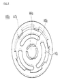
- FIG. 7 is a perspective view of the CID which is one of the elements of the cap assembly according to the present invention.
- the CID 440a is formed of a circular conductive sheet material.
- the CID 440a functions to discharge gas within the battery and also interrupt current within the battery and is disposed under the safety vent 430a.
- the CID 440a is formed of a circular metal sheet.
- the CID 440a includes the gas exhaust holes 442a and the central portion 444a formed at its central portion.
- the central portion 444a of the CID 440a is bonded with the projection portion 431a of the safety vent 430a.
- the CID 440a further includes the activator 446a and the support unit 448a which are integrated.
- the activator 446a has the notches formed on the concentric circle around the central portion 444a.
- the support unit 448a has an external diameter greater than the diameter of the activator and has a ring form over the activator.
- the CID 440a includes the activator 446a (i.e., a lower circular sheet portion) and the support unit 448a configured to have an external diameter greater than the diameter of the activator and disposed over the activator.
- FIG. 8 shows a cross section of the CID.
- the CID 440a includes the plurality of gas exhaust holes 442a formed on a lateral side and the central portion 444a formed at the center.
- the notches 443a are formed on the concentric circle around the central portion 444a.
- Three through holes and three notches 443a connecting the through holes are symmetrically formed on the concentric circle around the central portion 444a.
- FIG. 9 is a diagram showing the coupling of the elements of the cap assembly according to the present invention.
- the cap assembly of the present invention can be fabricated in such a way as to insert the auxiliary gasket 510a into the CID 440a, forcibly fit the safety vent 430a thereon, and surround the outer circumference of a stack in which the PTC element and the top cap are sequentially stacked with the gasket.
- FIG. 9 is the same as the structure of FIG. 1 in that the top cap, the PTC element, and the safety vent are adhered closely together and then surrounded with the gasket, but different from the structure of FIG. 1 in that the safety vent and the CID are fixed in a fitting state with the auxiliary gasket interposed therebetween and the CID is seated in the inclined portion or the terraced portion of the gasket so that the electrolyte can be additionally sealed.
- the dually sealed structure of the cap assembly according to the present invention is described below with reference to FIG. 10 .
- the electrolyte within the battery does not flow in the interface S1.
- the sealing state of the cap assembly is released partially or temporarily, and so the electrolyte can flow in the interface S1.
- the electrolyte within the battery flows in the interface S1 between the bottom surface of the safety vent 430a and the gasket 500a, the electrolyte can easily pass through the interface S2 between the safety vent 430a and the PTC element 420a, having a relatively low adhesion strength, or the interface S3 between the PTC element 420a and the top cap 410a and then leaks.
- the electrolyte must pass through the interface S4 between the CID 440a and the gasket 500a before the electrolyte is exposed to the interface S1 between the safety vent 430a and the gasket 500a in order to provide a stronger sealing strength.
- the electrolyte within the battery rarely flows in the interface S2 between the safety vent 430a and the PTC element 420 and the interface S3 between the PTC element 420 and the top cap 41 0a.
- the cylindrical secondary battery of the present invention includes the cap assembly of the present invention.
- any conventional technique and elements can be used as the remaining elements of the cylindrical secondary battery other than the cap assembly.
- the conventional technique and elements are widely known to a person having ordinary skill in the art, and a detailed description thereof is omitted.
- the cylindrical battery had the same shape and size and also had the same capacity and voltage.
- Table 1 COMPARISON EXAMPLE EMBODIMENT Leakage of electrolyte checked in 1 cycle (20/30) Leakage of electrolyte not checked until 20 cycles (0/30)
- the battery having the assembly structure of the present invention had no leakage of the electrolyte until 20 cycles. It can be understood that this result results from an excellent sealing strength because the assembly structure of the present invention is dually sealed for the electrolyte.
- the cap assembly of the present invention is dually sealed in order to prevent the leakage of an electrolyte. Accordingly, there is an advantage in that the safety of the battery can be greatly improved because the electrolyte rarely leaks although the battery is shocked because of dropping.
Landscapes
- Chemical & Material Sciences (AREA)
- Chemical Kinetics & Catalysis (AREA)
- Electrochemistry (AREA)
- General Chemical & Material Sciences (AREA)
- Connection Of Batteries Or Terminals (AREA)
- Gas Exhaust Devices For Batteries (AREA)
- Secondary Cells (AREA)
- Sealing Battery Cases Or Jackets (AREA)
Abstract
Description
- The present invention relates to a cap assembly and a battery including the same and, more particularly, to a cap assembly for a cylindrical secondary battery, in which the support unit of a current interrupt device (CID) is seated in the inclined portion or the terraced portion of a gasket and thus the battery is dually sealed, thereby preventing the leakage of an electrolyte, and a cylindrical secondary battery including the cylindrical secondary battery.
- A secondary battery is classified into a cylindrical battery and an angular battery in which an electrode assembly is embedded in a cylindrical or angular metal can and a pouch type battery in which an electrode assembly is embedded in the pouch type casing of an aluminum laminate sheet, depending on the shape of the battery casing.
- Further, the electrode assembly built in the battery casing is an electric generation device is configured to have a stack structure of a positive electrode, a separation film, and a negative electrode and can be charged and discharged. The electrode assembly is classified into a jelly-roll type structure in which the positive electrode and the negative electrode of a long sheet type, coated with an active material, are wound with the separation film interposed therebetween and a stack type structure in which the plurality of positive electrodes and the plurality of negative electrodes, having a specific size, are sequentially stacked with the separation film interposed therebetween. From among them, the electrode assembly of the jelly-roll type structure is most widely used because it is advantageous in terms of easy manufacture and a high energy density per weight. The electrode assembly of the jelly-roll type structure is chiefly used for the cylindrical battery.
- However, the electrode assembly of the jelly-roll type structure is likely to be deformed while experiencing repetitive expansion and contraction when the battery is charged and discharged. In this process, stress is concentrated on a central portion of the electrode assembly, and so the electrode penetrates the separation film and then brings into contact with a metal center pin, thereby causing an internal short. An organic solvent can be decomposed because of heat generated by the internal short and generate gas, and the battery can be exploded because of a rise in the gas pressure within the battery. Such a rise in the gas pressure within the battery can occur even when an internal short is generated by an external impact.
- In order to solve the safety problem of the battery, safety elements, such as a safety vent for exhausting a high-pressure gas, a positive temperature coefficient (hereinafter referred to as a 'PTC') element for interrupting current at high temperature, and a current interrupt device (hereinafter referred to as a 'CID') for interrupting current when an internal pressure within the battery rises, and a top cap forming a projection type terminal for protecting the elements are fixed by a gasket within the cap assembly of the cylindrical battery.
- The cap assembly is configured to prevent an electrolyte within the battery from fundamentally leaking externally in such a manner that the gasket surrounds the outer circumference, including the safety vent, the PTC element, the CID, and the top cap. Accordingly, if the electrolyte is not leaked through an interface of the safety vent placed on the innermost side of the battery and the gasket configured to surround the outer circumference of the safety vent, the electrolyte is not leaked through interfaces between metal materials, such as the interface of the safety vent and the PTC element and the interface of the PTC element and the top cap.
- However, some of the electrolyte is substantially leaked through the interface of the gasket and the safety vent in a process of charging and discharging the battery, because of dropping and an external impact, and so on. There is a problem in that the electrolyte can be easily leaked externally through the interfaces between the metal materials. That is, the interface between the metal materials is relatively low in the adhesion strength. Accordingly, the electrolyte once introduced into the interface between the metal materials can easily leak externally as compared with the interface between the gasket and its pertinent elements.
- Accordingly, there is a great need for a technique capable of reducing a phenomenon in which the electrolyte is leaked from the cap assembly.
- In line with the necessity, Japanese Unexamined Patent Application Publication No.
2006-286561 2005-100927 2002-373711 -
FIG. 1 is a cross-sectional view showing the upper structure of a conventional cylindrical secondary battery. - Referring to
FIG. 1 , thebattery 100 is fabricated by inserting an electrode assembly 300 (i.e., an electric generation device) into acan 200, injecting an electrolyte into thecan 200, and mounting acap assembly 400 on the upper opening of thecan 200. - The
cap assembly 400 includes atop cap 410, aPTC element 420 for interrupting overcurrent, and asafety vent 430 for lowering an internal pressure. Thetop cap 410, thePTC element 420, and thesafety vent 430 are closely adhered and disposed within agasket 500 configured to maintain airtightness and mounted on the upper beadingunit 210 of thecan 200. - The
top cap 410 has a central portion projected upward and functions as a positive electrode terminal through a contact with an external circuit. A plurality of penetration holes (not shown) for exhausting gas is perforated in thetop cap 410. Thesafety vent 430 has its bottom connected to the positive electrode of theelectrode assembly 300 via a currentinterruption safety device 440 and apositive electrode lead 310. - The
safety vent 430 is made of a thin conductive sheet material. Adownward indentation portion 432 is formed in a central portion of thesafety vent 430, and two notches with different depths are formed at the upper curved portion and the lower curved portion of thedownward indentation portion 432. - The current
interruption safety device 440 is disposed under thesafety vent 430 made of the conductive sheet material and it functions to interrupt current when pressure within the battery is higher than a critical value. The currentinterruption safety device 440 preferably is made of the same material as thesafety vent 430. Anauxiliary gasket 510 is made of polypropylene (PP)-based materials so that it can prevent the currentinterruption safety device 440 and thesafety vent 430 from becoming electrified. - For example, when a temperature of the
battery 100 rises because of an internal short, overcharge, etc. caused by various causes, the amount of electrified current is greatly reduced by an increase in the resistance of thePTC element 420. If the electrolyte is decomposed by a continued rise in the temperature, thus generating gas, and resultantly an internal pressure rises, thedownward indentation portion 432 of thesafety vent 430 is raised up and the currentinterruption safety device 440 is partially ruptured to interrupt current, thereby guaranteeing safety. If the pressure continues to rise, thenotches 436 of thesafety vent 430 are ruptured and so a high-pressure gas is exhausted outside thebattery 100 in order to guarantee safety. - Accordingly, the present invention has been made keeping in mind the above problems occurring in the prior art.
- The inventors of the present application, as a result of depth research and various experiments, have found that the safety of a battery can be greatly improved if a safety vent and a CID are fixed together in a fitting state and the CID is seated in the inclined portion or the terraced portion of a gasket so that the CID can be additionally fixed between the safety vent and the gasket and thus have completed the present invention.
- In accordance with an aspect of the present invention, there is provided a cap assembly, comprising a top cap configured to include gas exhaust holes and form a projection terminal; a safety vent formed of a circular metal sheet and configured to have a projection portion formed at a center and two or more notches formed on a concentric circle around the projection portion; a current interrupt device (CID) formed of a circular metal sheet and configured to have gas exhaust holes, a central portion bonded with the projection portion of the safety vent and formed at a center, an activator having notches formed on a concentric circle around the central portion of the CID, and a support unit having an external diameter greater than a diameter of the activator and having a ring shape over the activator; and a gasket configured to have an inclined portion or a terraced portion and to surround and seal an outer circumference of the constituent elements. The safety vent and the CID are fixed together in a fitting state with an auxiliary gasket interposed therebetween. The support unit of the CID is seated in the inclined portion or the terraced portion of the gasket, thereby additionally fixing the CID between the safety vent and the gasket. The bonding strength between an indentation central portion of the safety vent and the projection portion of the CID is greater than the rupture strength of each of all the notches formed in the safety vent and the CID.
- Further, in the present invention, the safety vent comprises a Z-shaped projected fitting unit, the CID comprises engagement units between the activator and the support unit, and the Z-shaped projected fitting unit of the safety vent and the engagement units of the CID are fitted and fixed together with the auxiliary gasket interposed therebetween.
- Further, in the present invention, the fitting state includes a forced fitting state.
- Further, in the present invention, the place where the support unit of the CID is seated in the gasket is within an area of a beading unit.
- Further, in the present invention, the gas exhaust holes of the top cap and the gas exhaust holes of the CID are provided in an identical location from a viewpoint of an axial direction.
- Further, in the present invention, the cap assembly further comprises a positive temperature coefficient (PTC) element between the top cap and the safety vent.
- Further, in the present invention, the support unit of the CID is seated in the inclined portion or the terraced portion of the gasket and so a battery is dually sealed for a leakage of an electrolyte.
- Further, the present invention provides a cylindrical secondary battery comprising the cap assembly.
- The above and other objects and features of the present invention will become apparent from the following description of preferred embodiments given in conjunction with the accompanying drawings, in which:
-
FIG. 1 is a cross-sectional view showing the upper structure of a conventional cylindrical secondary battery; -
FIG. 2 is a diagram showing the structure of a cap assembly according to an embodiment of the present invention; -
FIG. 3 is a diagram showing the structure of a cap assembly according to another embodiment of the present invention; -
FIG. 4 is a diagram showing a top cap which is one of the elements of the cap assembly according to the present invention; -
FIG. 5 is a perspective view of a safety vent which is one of the elements of the cap assembly according to the present invention; -
FIG. 6 is a cross-sectional view of the safety vent which is one of the elements of the cap assembly according to the present invention; -
FIG. 7 is a perspective view of a CID which is one of the elements of the cap assembly according to the present invention; -
FIG. 8 is a cross-sectional view of the CID which is one of the elements of the cap assembly according to the present invention; -
FIG. 9 is a diagram showing the coupling of the elements of the cap assembly according to the present invention; and -
FIG. 10 is a diagram showing that the cap assembly of the present invention is dually sealed. - Hereinafter, embodiments of the present invention will be described in detail with reference to the accompanying drawings so that they can be readily implemented by those skilled in the art.
- The cap assembly of the present invention comprises a top cap configured to include gas exhaust holes and form a projection terminal; a safety vent formed of a circular metal sheet and configured to have a projection portion formed at its center and two or more notches formed on the concentric circle around the projection portion; a current interrupt device (CID) formed of a circular metal sheet and configured to have gas exhaust holes, a central portion bonded with the projection portion of the safety vent and formed at its center, an activator having notches formed on the concentric circle around the central portion of the CID, and a support unit having an external diameter greater than the diameter of the activator and having a ring shape over the activator; and a gasket configured to have an inclined portion or a terraced portion and to surround and seal the outer circumference of the constituent elements.
- The safety vent and the CID are fixed together in a fitting state with an auxiliary gasket interposed therebetween. The support unit of the CID is seated in the inclined portion or the terraced portion of the gasket, thereby additionally fixing the CID between the safety vent and the gasket. The bonding strength between the indentation central portion of the safety vent and the projection portion of the CID is greater than the rupture strength of each of all the notches formed in the safety vent and the CID.
- In the present invention, the safety vent and the CID are fixed together in a fitting state with the auxiliary gasket interposed therebetween.
- In general, the CID is fixed to the safety vent and provided in the assembly. The central portion of the CID is welded to the projection portion of the safety vent and bonded thereto. However, the problem is that if the battery is shocked because of causes, such as dropping, a short can occur at the shocked portion of the battery. If the CID is separated from the safety vent, the CID can freely move within the battery. Accordingly, there is a danger that the CID can generate a short of the battery.
- Accordingly, in order to stably fix and couple the CID and the safety vent, the safety vent and the CID are fixed in a fitting state.
- The safety vent can include a Z-shaped projected fitting unit, as shown in
FIG. 3 , and the CID can include engagement units between the activator and the support unit, as shown inFIGS. 7 and8 . Each of the engagement units can include a hole in which the fitting unit of the safety vent can be seated and a latch functioning to fix the auxiliary gasket and the fitting unit to the hole. The fitting unit of the safety vent and the engagement unit of the CID preferably are fitted together and fixed with the auxiliary gasket interposed therebetween. In particular, it is more preferred that the fitting state be a forced fitting state so that the CID can be more robustly fixed. The term 'forced fitting' refers to the degree of tolerance between an inserted portion (for example, a shaft) and a mated portion (for example, a hole). The term 'forced fitting' is widely used in the design of a machine, and the definition 'forced fitting' in the present specification follows the design of a machine which is commonly widely used. - In the present invention, the CID includes the support unit, and the support unit of the CID is seated in the inclined portion or the terraced portion of the gasket. Accordingly, the CID can be further fixed between the safety vent and the gasket.
- The inclined portion of the gasket can be naturally formed when the gasket is clamped. When the gasket, together with the can, is clamped as in
FIG. 3 , part of the gasket is put over the beading unit, and the remaining of the gasket is protruded into the inside of the can. Here, the gasket is bent at a specific angle in the direction of gravity and thus the inclined portion of the gasket can be formed. - Meanwhile, when the support unit of the CID is seated in the inclined portion of the gasket and pressure is applied between the support unit of the CID and the gasket in a process of the gasket being clamped, part of the gasket is pushed and thus the terraced portion of the gasket may be naturally formed. If in the clamping process, pressure is not applied between the support unit of the CID and the gasket, the support unit of the CID may be placed in the inclined portion of the gasket with it seated therein.
- In addition to the above method, a method of forming a predetermined inclined portion or terraced portion in the gasket can be also used. In other words, a terraced portion may be formed in the gasket in such a way as to artificially dig a groove in the gasket in addition to a special process.
- When the CID is additionally fixed as described above, there is an advantage in that the CID can be more robustly supported when the battery is shocked by causes, such as dropping. In other words, in a conventional battery structure, the CID is simply welded and fixed to the safety vent. In the assembly of the present invention, although the battery is shocked, safety is high because the CID is fixed to the safety vent in a fitting state. In particular, even in the case in which a bonding portion between the CID and the safety vent is separated because of an impact applied to the battery, the CID is closely fixed to the safety vent. Accordingly, safety is very high as compared with the conventional battery structure.
- Furthermore, since the support unit of the CID is seated in the inclined portion or the terraced portion of the gasket, there is an advantage in that the battery is dually sealed for the leakage of an electrolyte.
- In a normal state or normal operation condition of the battery, the electrolyte within the battery does not flow in the interface. However, when external force is applied or an internal pressure rises, the sealing state of the cap assembly can be released partially or temporarily, and thus the electrolyte can flow in the interface. When the electrolyte within the battery flows in the interface between the bottom surface of the safety vent and the gasket, the electrolyte easily passes through the interface between a PTC element and the safety vent having relatively low adhesion strength or the interface between the PTC element and the top cap and then leaks.
- In the assembly structure of the present invention, however, as shown in
FIG. 10 , the electrolyte must pass through the interface between the CID and the gasket before it is exposed to the interface between the safety vent and the gasket. Accordingly, a higher sealing strength can be provided. - In particular, it is preferred that a place where the support unit of the CID is seated in the gasket be within the area of the beading unit. In the present invention, however, the place where the support unit of the CID is seated in the gasket is not specially limited. In order to support the CID, the support unit of the CID can be extended in the same length as the remaining elements, such as the safety vent, as shown in
FIG. 2 , and can have the same outer circumference as the remaining elements. In this case, the thickness of the assembly is increased, and the volume of an electrode assembly is reduced as much as the increment. Accordingly, such a method is not preferred because the capacity of the battery may be reduced. For this reason, it is preferred that the place where the support unit of the CID is seated in the gasket be within the area of the beading unit, as shown inFIG. 3 . - In the present invention, the bonding strength between the indentation central portion of the safety vent and the projection portion of the CID should be greater than the rupture strength of each of all the notches formed in the safety vent and the CID. This is because the bonding of the indentation central portion of the safety vent and the projection portion of the CID should not be untied at least until the notch of the safety vent is ruptured and opened. If the bonding is untied before the notch of the safety vent is ruptured, there is a danger that the current interruption effect of the CID member may not be generated. Accordingly, it is better that the bonding strength between the indentation central portion of the safety vent and the projection portion of the CID is stronger, and the upper limit of the bonding strength is not limited. In this respect, the present invention significantly differs from the prior art in which the welding between the safety vent and other elements, such as a lead sheet, is untied in a specific pressure.
- In the present invention, it is preferred that gas exhaust holes provided in the top cap and gas exhaust holes provided in the CID be provided in the same location from a viewpoint of an axial direction. When the gas exhaust holes are formed in the same location, generated gas can be exhausted without a curved path, and so the safety of the battery can be increased.
- In the present invention, the PTC element can be further included between the top cap and the safety vent. Although the PTC element is in general interposed between the top cap and the safety vent, the PTC element may not necessarily interposed between the top cap and the safety vent. The PTC element has its resistance greatly rising when temperature of the battery rises, thus interrupting current. The PTC element is widely known in the art to which the present invention pertains, and a further description thereof is omitted. In the present invention, a conventional PTC element can be used without limitation.
- Hereinafter, some embodiments of the present invention are described in more detail with reference to the accompanying drawings. The embodiments are provided to help understand the present invention and are not intended to limit the scope of the present invention thereto.
-
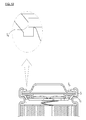
FIG. 3 shows the structure of a cap assembly according to an embodiment of the present invention. - Referring to
FIG. 3 , thecap assembly 400a includes thetop cap 410a within thegasket 500a configured to maintain airtightness and mounted on theupper beading unit 210a of thecan 200a, thePTC element 420a for current interruption, the safety vent for dropping internal pressure, and theCID 440a which are closed together. The cylindricalsecondary battery 100a can be fabricated by inserting the electrode assembly into thecan 200a, injecting the electrolyte thecan 200a, and mounting thecap assembly 400a on the top open end of thecan 200a. -
FIG. 4 is a diagram showing the top cap which is one of the elements of the cap assembly according to the present invention. - The
top cap 410a has its central portion upwardly protruded and functions as a positive electrode terminal through a connection with an external circuit. The plurality ofgas exhaust holes 412a to exhaust compressed gas is formed along the protruded circumference of thetop cap 410a within thecan 200a. -
FIGS. 5 and6 show the safety vent which is one of the elements of the cap assembly according to the present invention. - The
safety vent 430a is a thin film structure of a circular sheet form through which current can flow. Thenotches safety vent 430a. Thenotches notches projection portion 431 a. The center of the upper curved portion and the lower curved portion is bonded with thecentral portion 444a of theCID 440a. - As shown in
FIGS. 3 ,5 , and6 , in thesafety vent 430a, thefirst notch 432a formed on the upper side of thenotches second notch 433a formed on the lower side of thenotches projection portion 431 a from being fully separated from thesafety vent 430a when thesecond notch 433a is ruptured by internal pressure. If theprojection portion 431 a is fully separated from thesafety vent 430a, it can freely move within the battery and cause to generate a short. Further, since the bonding strength of thesecond notch 433a is smaller than the bonding strength of thefirst notch 432a, thesecond notch 433a is dug deeper than thefirst notch 432a. - When the internal pressure of the
can 200a is higher than a critical pressure, thesafety vent 430a is upward deformed by thenotches projection portion 431 a is lifted up, and thecentral portion 444a of theCID 440a, bonded to the bottom of thesafety vent 430a, is separated from the main body of the CID. Accordingly, additional current is interrupted to suppress the generation of gas. If gas continues to be generated, thesecond notch 433a of thesafety vent 430a is ruptured by the internal pressure, and so pressurized gas within thecan 200a is drained through thegas exhaust holes 412a of thetop cap 410a. Accordingly, the safety of the battery can be guaranteed. - In particular, the
safety vent 430a can include the Z-shaped projectedfitting unit 437a. As shown inFIG. 3 , the Z-shaped projectedfitting unit 437a functions to fix theCID 440a placed under thesafety vent 430a. As will be described later, theCID 440a includes theengagement units 447a between the activator 446a and the support unit 448a. Accordingly, the Z-shaped projectedfitting unit 437a of thesafety vent 430a and theengagement units 447a of theCID 440a can be fitted together and fixed with theauxiliary gasket 510a interposed therebetween. It is preferred that the fitting state be a forced fitting state. This is because in the forced fitting state, the CID can be stably fixed to the safety vent although the central portion of the CID is separated from the main body of the CID. -
FIG. 7 is a perspective view of the CID which is one of the elements of the cap assembly according to the present invention. - The
CID 440a is formed of a circular conductive sheet material. TheCID 440a functions to discharge gas within the battery and also interrupt current within the battery and is disposed under thesafety vent 430a. - The
CID 440a is formed of a circular metal sheet. TheCID 440a includes thegas exhaust holes 442a and thecentral portion 444a formed at its central portion. Thecentral portion 444a of theCID 440a is bonded with theprojection portion 431a of thesafety vent 430a. TheCID 440a further includes the activator 446a and the support unit 448a which are integrated. The activator 446a has the notches formed on the concentric circle around thecentral portion 444a. The support unit 448a has an external diameter greater than the diameter of the activator and has a ring form over the activator. That is, theCID 440a includes the activator 446a (i.e., a lower circular sheet portion) and the support unit 448a configured to have an external diameter greater than the diameter of the activator and disposed over the activator.FIG. 8 shows a cross section of the CID. - The
CID 440a includes the plurality ofgas exhaust holes 442a formed on a lateral side and thecentral portion 444a formed at the center. Thenotches 443a are formed on the concentric circle around thecentral portion 444a. Three through holes and threenotches 443a connecting the through holes are symmetrically formed on the concentric circle around thecentral portion 444a. When pressurized gas is applied to thesafety vent 430a because of a rise in the pressure within the battery, theprojection portion 431 a of thesafety vent 430a is lifted up, and thecentral portion 444a welded to theprojection portion 431 a is separated from the main body of theCID 440a as thenotches 443a are cut away. -
FIG. 9 is a diagram showing the coupling of the elements of the cap assembly according to the present invention. As shown inFIG. 9 , the cap assembly of the present invention can be fabricated in such a way as to insert theauxiliary gasket 510a into theCID 440a, forcibly fit thesafety vent 430a thereon, and surround the outer circumference of a stack in which the PTC element and the top cap are sequentially stacked with the gasket. - The structure of
FIG. 9 is the same as the structure ofFIG. 1 in that the top cap, the PTC element, and the safety vent are adhered closely together and then surrounded with the gasket, but different from the structure ofFIG. 1 in that the safety vent and the CID are fixed in a fitting state with the auxiliary gasket interposed therebetween and the CID is seated in the inclined portion or the terraced portion of the gasket so that the electrolyte can be additionally sealed. - The dually sealed structure of the cap assembly according to the present invention is described below with reference to
FIG. 10 . - When the battery is in a normal state or normal operation condition, the electrolyte within the battery does not flow in the interface S1. However, when external force is applied or internal pressure rises, the sealing state of the cap assembly is released partially or temporarily, and so the electrolyte can flow in the interface S1. When the electrolyte within the battery flows in the interface S1 between the bottom surface of the
safety vent 430a and thegasket 500a, the electrolyte can easily pass through the interface S2 between thesafety vent 430a and thePTC element 420a, having a relatively low adhesion strength, or the interface S3 between thePTC element 420a and thetop cap 410a and then leaks. - In the structure of the present invention, however, the electrolyte must pass through the interface S4 between the
CID 440a and thegasket 500a before the electrolyte is exposed to the interface S1 between thesafety vent 430a and thegasket 500a in order to provide a stronger sealing strength. In particular, although external force is applied, the battery is dropped, or internal pressure rises, the electrolyte within the battery rarely flows in the interface S2 between thesafety vent 430a and thePTC element 420 and the interface S3 between thePTC element 420 and the top cap 41 0a. - The cylindrical secondary battery of the present invention includes the cap assembly of the present invention.
- Any conventional technique and elements can be used as the remaining elements of the cylindrical secondary battery other than the cap assembly. The conventional technique and elements are widely known to a person having ordinary skill in the art, and a detailed description thereof is omitted.
- An experiment for checking whether an electrolyte leaked because of an impulse was performed in relation to the embodiment of the present invention. In a comparison example, the battery of the conventional assembly structure, such as that shown in
FIG. 1 , was used. - In the embodiment and the comparison example, the cylindrical battery had the same shape and size and also had the same capacity and voltage.
- In an experiment condition, after the cylindrical battery was dropped on a concrete from the height of about 1.2 m, whether the electrolyte had leaked was checked. In relation to a direction in which the battery was dropped, three methods of dropping the battery with an upper portion (a portion in which the cap assembly was seated) directed downward; dropping the battery with the side of the battery directed downward; and dropping the battery with an upper portion of the battery directed upward were used.
- Whether the electrolyte had leaked was checked using the three kinds of methods as one cycle. The experiment was carried out by 20 cycles in total, and the number of batteries used was 30 in each of the embodiment and the comparison example.
- A result of the experiment was listed in Table 1 below.
Table 1 COMPARISON EXAMPLE EMBODIMENT Leakage of electrolyte checked in 1 cycle (20/30) Leakage of electrolyte not checked until 20 cycles (0/30) - As shown in Table 1, the battery having the assembly structure of the present invention had no leakage of the electrolyte until 20 cycles. It can be understood that this result results from an excellent sealing strength because the assembly structure of the present invention is dually sealed for the electrolyte.
- The cap assembly of the present invention is dually sealed in order to prevent the leakage of an electrolyte. Accordingly, there is an advantage in that the safety of the battery can be greatly improved because the electrolyte rarely leaks although the battery is shocked because of dropping.
- While the invention has been shown and described with respect to the preferred embodiments, it will be understood by those skilled in the art that various changes and modifications may be made without departing from the spirit and scope of the invention as defined in the following claims.
Claims (8)
- A cap assembly, comprising:a top cap configured to include gas exhaust holes and form a projection terminal;a safety vent formed of a circular metal sheet and configured to have a projection portion formed at a center and two or more notches formed on a concentric circle around the projection portion;a current interrupt device (CID) formed of a circular metal sheet and configured to have gas exhaust holes, a central portion bonded with the projection portion of the safety vent and formed at a center, an activator having notches formed on a concentric circle around the central portion of the CID, and a support unit having an external diameter greater than a diameter of the activator and having a ring shape over the activator; anda gasket configured to have an inclined portion or a terraced portion and to surround and seal an outer circumference of the constituent elements,wherein the safety vent and the CID are fixed together in a fitting state with an auxiliary gasket interposed therebetween,a support unit of the CID is seated in the inclined portion or the terraced portion of the gasket, thereby additionally fixing the CID between the safety vent and the gasket, anda bonding strength between an indentation central portion of the safety vent and the projection portion of the CID is greater than a rupture strength of each of all the notches formed in the safety vent and the CID.
- The cap assembly of claim 1, wherein:the safety vent comprises a Z-shaped projected fitting unit,the CID comprises engagement units between the activator and the support unit, andthe Z-shaped projected fitting unit of the safety vent and the engagement units of the CID are fitted and fixed together with the auxiliary gasket interposed therebetween.
- The cap assembly of claim 1, wherein the fitting state includes a forced fitting state.
- The cap assembly of claim 1, wherein a place where the support unit of the CID is seated in the gasket is within an area of a beading unit.
- The cap assembly of claim 1, wherein the gas exhaust holes of the top cap and the gas exhaust holes of the CID are provided in an identical location from a viewpoint of an axial direction.
- The cap assembly of claim 1, further comprising a positive temperature coefficient (PTC) element between the top cap and the safety vent.
- The cap assembly of claim 1, wherein the support unit of the CID is seated in the inclined portion or the terraced portion of the gasket and so a battery is dually sealed for a leakage of an electrolyte.
- A cylindrical secondary battery comprising a cap assembly according to any one of claims 1 to 7.
Applications Claiming Priority (2)
| Application Number | Priority Date | Filing Date | Title |
|---|---|---|---|
| KR1020090093428A KR101062685B1 (en) | 2009-09-30 | 2009-09-30 | Double sealed cap assembly, and cylindrical secondary battery having the same |
| PCT/KR2010/003475 WO2011040692A1 (en) | 2009-09-30 | 2010-05-31 | Double-sealed cap assembly and cylindrical secondary battery comprising same |
Publications (3)
| Publication Number | Publication Date |
|---|---|
| EP2472634A1 true EP2472634A1 (en) | 2012-07-04 |
| EP2472634A4 EP2472634A4 (en) | 2013-11-06 |
| EP2472634B1 EP2472634B1 (en) | 2015-03-25 |
Family
ID=43826474
Family Applications (1)
| Application Number | Title | Priority Date | Filing Date |
|---|---|---|---|
| EP10820765.5A Active EP2472634B1 (en) | 2009-09-30 | 2010-05-31 | Double-sealed cap assembly and cylindrical secondary battery comprising same |
Country Status (6)
| Country | Link |
|---|---|
| EP (1) | EP2472634B1 (en) |
| JP (1) | JP5551781B2 (en) |
| KR (1) | KR101062685B1 (en) |
| CN (1) | CN102549802B (en) |
| TW (1) | TWI414098B (en) |
| WO (1) | WO2011040692A1 (en) |
Cited By (4)
| Publication number | Priority date | Publication date | Assignee | Title |
|---|---|---|---|---|
| WO2014102578A1 (en) * | 2012-12-27 | 2014-07-03 | Toyota Jidosha Kabushiki Kaisha | Sealed battery and manufacturing method of sealed battery |
| EP2760062A4 (en) * | 2011-12-26 | 2014-11-05 | Lg Chemical Ltd | Cap assembly having improved manufacturing processability and cylindrical battery comprising same |
| EP3525262A4 (en) * | 2016-12-16 | 2020-06-03 | Murata Manufacturing Co., Ltd. | Secondary battery, battery pack, electric vehicle, power storage system, power tool, and electronic apparatus |
| US11417906B2 (en) | 2017-02-09 | 2022-08-16 | Lg Energy Solution, Ltd. | Cylindrical lithium secondary battery |
Families Citing this family (10)
| Publication number | Priority date | Publication date | Assignee | Title |
|---|---|---|---|---|
| KR101634764B1 (en) * | 2013-09-24 | 2016-06-29 | 주식회사 엘지화학 | Cap Assembly Comprising Safety Member Having Protrusion Part being formed for Preventing Leak Path and Lithium Secondary Battery Comprising The Same |
| KR102194984B1 (en) | 2014-04-08 | 2020-12-28 | 삼성에스디아이 주식회사 | Rechargeable battery |
| KR101678735B1 (en) | 2014-10-02 | 2016-11-23 | 주식회사 엘지화학 | Secondary Battery Top Cap Assembly |
| US10490792B2 (en) | 2015-06-05 | 2019-11-26 | Lg Chem, Ltd. | Cap assembly for secondary battery |
| KR20170121636A (en) | 2016-04-25 | 2017-11-02 | 삼성에스디아이 주식회사 | Secondary battery |
| CN111954914B (en) * | 2018-03-30 | 2023-01-06 | 松下知识产权经营株式会社 | Electricity storage module |
| KR102610593B1 (en) * | 2019-06-18 | 2023-12-07 | 주식회사 엘지에너지솔루션 | Cylindrical Secondary Battery Comprising Gasket with Groove |
| TWI715406B (en) | 2020-01-06 | 2021-01-01 | 財團法人工業技術研究院 | Battery safety device |
| KR20210100493A (en) * | 2020-02-06 | 2021-08-17 | 주식회사 엘지에너지솔루션 | Cap assembly, secondary battery and battery pack comprising the same |
| JPWO2021172233A1 (en) * | 2020-02-28 | 2021-09-02 |
Citations (2)
| Publication number | Priority date | Publication date | Assignee | Title |
|---|---|---|---|---|
| JPH06196140A (en) * | 1992-12-25 | 1994-07-15 | Sanyo Electric Co Ltd | Explosion-proof type sealed battery |
| WO2008069476A1 (en) * | 2006-12-05 | 2008-06-12 | Moon, Seung-Ja | Cylindrical secondary battery and method of manufacturing the same |
Family Cites Families (14)
| Publication number | Priority date | Publication date | Assignee | Title |
|---|---|---|---|---|
| JP2701375B2 (en) * | 1988-10-21 | 1998-01-21 | ソニー株式会社 | Explosion-proof sealed battery |
| JP2001325935A (en) * | 2000-03-10 | 2001-11-22 | Sanyo Electric Co Ltd | Sealed alkaline battery |
| JP2002343315A (en) * | 2001-05-10 | 2002-11-29 | Alps Electric Co Ltd | Battery cap unit |
| TWM245602U (en) * | 2001-05-24 | 2004-10-01 | Nanya Plastics Corp | Improved safety and explosion-proof structure of cylinder lithium ion battery |
| JP2002373711A (en) | 2001-06-13 | 2002-12-26 | Toshiba Battery Co Ltd | Button type air-zinc battery and its method of manufacture |
| JP4612321B2 (en) * | 2003-04-04 | 2011-01-12 | 株式会社東芝 | Nonaqueous electrolyte secondary battery |
| JP4567374B2 (en) | 2003-08-28 | 2010-10-20 | パナソニック株式会社 | Battery and manufacturing method thereof |
| JP2006286561A (en) | 2005-04-05 | 2006-10-19 | Matsushita Electric Ind Co Ltd | Sealing plate for sealed battery |
| KR100878701B1 (en) * | 2006-03-13 | 2009-01-14 | 주식회사 엘지화학 | High Rate Charging and Discharging Cylindrical Secondary Battery |
| KR100973423B1 (en) * | 2006-10-16 | 2010-08-02 | 주식회사 엘지화학 | Cylindrical Battery of Improved Safety |
| KR101054748B1 (en) * | 2007-06-14 | 2011-08-05 | 주식회사 엘지화학 | Secondary battery cap assembly with excellent electrolyte sealing |
| KR100882915B1 (en) * | 2007-07-03 | 2009-02-10 | 삼성에스디아이 주식회사 | Secondary Battery |
| TWM355464U (en) * | 2008-09-26 | 2009-04-21 | Taiwan Hon Chuan Entpr Co Ltd | Anti-explosion safety valve of battery |
| US8486546B2 (en) * | 2008-12-01 | 2013-07-16 | Samsung Sdi Co., Ltd. | Cap assembly and secondary battery using the same with notched vent member |
-
2009
- 2009-09-30 KR KR1020090093428A patent/KR101062685B1/en active IP Right Grant
-
2010
- 2010-05-31 WO PCT/KR2010/003475 patent/WO2011040692A1/en active Application Filing
- 2010-05-31 JP JP2012531994A patent/JP5551781B2/en active Active
- 2010-05-31 EP EP10820765.5A patent/EP2472634B1/en active Active
- 2010-05-31 CN CN201080043929.2A patent/CN102549802B/en active Active
- 2010-06-15 TW TW099119528A patent/TWI414098B/en active
Patent Citations (2)
| Publication number | Priority date | Publication date | Assignee | Title |
|---|---|---|---|---|
| JPH06196140A (en) * | 1992-12-25 | 1994-07-15 | Sanyo Electric Co Ltd | Explosion-proof type sealed battery |
| WO2008069476A1 (en) * | 2006-12-05 | 2008-06-12 | Moon, Seung-Ja | Cylindrical secondary battery and method of manufacturing the same |
Non-Patent Citations (1)
| Title |
|---|
| See also references of WO2011040692A1 * |
Cited By (7)
| Publication number | Priority date | Publication date | Assignee | Title |
|---|---|---|---|---|
| EP2760062A4 (en) * | 2011-12-26 | 2014-11-05 | Lg Chemical Ltd | Cap assembly having improved manufacturing processability and cylindrical battery comprising same |
| US9178190B2 (en) | 2011-12-26 | 2015-11-03 | Lg Chem, Ltd. | Cap assembly having improved manufacturing processability and cylindrical battery comprising same |
| WO2014102578A1 (en) * | 2012-12-27 | 2014-07-03 | Toyota Jidosha Kabushiki Kaisha | Sealed battery and manufacturing method of sealed battery |
| US10069130B2 (en) | 2012-12-27 | 2018-09-04 | Toyota Jidosha Kabushiki Kaisha | Sealed battery and manufacturing method of sealed battery |
| EP3525262A4 (en) * | 2016-12-16 | 2020-06-03 | Murata Manufacturing Co., Ltd. | Secondary battery, battery pack, electric vehicle, power storage system, power tool, and electronic apparatus |
| US11581568B2 (en) | 2016-12-16 | 2023-02-14 | Murata Manufacturing Co., Ltd. | Secondary battery, battery pack, electric vehicle, power storage system, power tool, and electronic device |
| US11417906B2 (en) | 2017-02-09 | 2022-08-16 | Lg Energy Solution, Ltd. | Cylindrical lithium secondary battery |
Also Published As
| Publication number | Publication date |
|---|---|
| TW201112470A (en) | 2011-04-01 |
| KR101062685B1 (en) | 2011-09-06 |
| TWI414098B (en) | 2013-11-01 |
| JP5551781B2 (en) | 2014-07-16 |
| CN102549802B (en) | 2015-04-01 |
| CN102549802A (en) | 2012-07-04 |
| EP2472634B1 (en) | 2015-03-25 |
| WO2011040692A1 (en) | 2011-04-07 |
| EP2472634A4 (en) | 2013-11-06 |
| JP2013506954A (en) | 2013-02-28 |
| KR20110035625A (en) | 2011-04-06 |
Similar Documents
| Publication | Publication Date | Title |
|---|---|---|
| EP2472634B1 (en) | Double-sealed cap assembly and cylindrical secondary battery comprising same | |
| US9620751B2 (en) | Dual sealing cap assembly and cylindrical secondary battery including the same | |
| KR100878701B1 (en) | High Rate Charging and Discharging Cylindrical Secondary Battery | |
| KR100948001B1 (en) | Lithium Ion Battery of Crimping Shape of Increased Safety | |
| US20090263703A1 (en) | Cap assembly and secondary battery using the same | |
| KR101768656B1 (en) | Cap assembly and secondary battery including the same | |
| KR102056363B1 (en) | Battery Cell | |
| KR20170109919A (en) | Rechargeable battery | |
| KR101054748B1 (en) | Secondary battery cap assembly with excellent electrolyte sealing | |
| KR100696782B1 (en) | Lithium Ion Secondary Battery | |
| KR20110029061A (en) | Secondary battery | |
| KR20020071179A (en) | Secondary battery and the fabrication method therof | |
| JP5551785B2 (en) | Cap assembly in which sagging of gasket is prevented, and cylindrical secondary battery including the same | |
| KR100938062B1 (en) | Rechargeable battery and the fabricating method thereof | |
| KR20120052586A (en) | Cap assembly and secondary battery using the same | |
| KR101520064B1 (en) | Method for producing cap assembly, cap assembly thereby and secondary battery having the same | |
| US8420257B2 (en) | Cap assembly comprising gasket prevented from sagging | |
| KR102010443B1 (en) | Cap-assembly for a secondary battery with durability | |
| KR20120047114A (en) | Secondary battery | |
| KR20100128679A (en) | Secondary battery having a plastic-bag, and manufacturing the same | |
| KR20060088312A (en) | Cap assembly and lithium ion secondary battery with the same | |
| US20230411748A1 (en) | Secondary battery | |
| KR20170053392A (en) | Beading-less cap assembly with modifed gasket structure | |
| CN114600288A (en) | Cylindrical secondary battery having flexible input portion | |
| KR20210056159A (en) | Cap Assembly with Fixing Member and Secondary Battery Comprising the Same |
Legal Events
| Date | Code | Title | Description |
|---|---|---|---|
| PUAI | Public reference made under article 153(3) epc to a published international application that has entered the european phase |
Free format text: ORIGINAL CODE: 0009012 |
|
| 17P | Request for examination filed |
Effective date: 20120326 |
|
| AK | Designated contracting states |
Kind code of ref document: A1 Designated state(s): AL AT BE BG CH CY CZ DE DK EE ES FI FR GB GR HR HU IE IS IT LI LT LU LV MC MK MT NL NO PL PT RO SE SI SK SM TR |
|
| DAX | Request for extension of the european patent (deleted) | ||
| REG | Reference to a national code |
Ref country code: DE Ref legal event code: R079 Ref document number: 602010023501 Country of ref document: DE Free format text: PREVIOUS MAIN CLASS: H01M0002080000 Ipc: H01M0002100000 |
|
| A4 | Supplementary search report drawn up and despatched |
Effective date: 20131009 |
|
| RIC1 | Information provided on ipc code assigned before grant |
Ipc: H01M 2/04 20060101ALI20131002BHEP Ipc: H01M 2/10 20060101AFI20131002BHEP Ipc: H01M 2/34 20060101ALI20131002BHEP Ipc: H01M 2/12 20060101ALI20131002BHEP |
|
| GRAP | Despatch of communication of intention to grant a patent |
Free format text: ORIGINAL CODE: EPIDOSNIGR1 |
|
| INTG | Intention to grant announced |
Effective date: 20141212 |
|
| GRAS | Grant fee paid |
Free format text: ORIGINAL CODE: EPIDOSNIGR3 |
|
| GRAA | (expected) grant |
Free format text: ORIGINAL CODE: 0009210 |
|
| AK | Designated contracting states |
Kind code of ref document: B1 Designated state(s): AL AT BE BG CH CY CZ DE DK EE ES FI FR GB GR HR HU IE IS IT LI LT LU LV MC MK MT NL NO PL PT RO SE SI SK SM TR |
|
| REG | Reference to a national code |
Ref country code: GB Ref legal event code: FG4D |
|
| REG | Reference to a national code |
Ref country code: CH Ref legal event code: EP |
|
| REG | Reference to a national code |
Ref country code: IE Ref legal event code: FG4D |
|
| REG | Reference to a national code |
Ref country code: DE Ref legal event code: R096 Ref document number: 602010023501 Country of ref document: DE Effective date: 20150507 |
|
| REG | Reference to a national code |
Ref country code: FR Ref legal event code: PLFP Year of fee payment: 6 |
|
| REG | Reference to a national code |
Ref country code: AT Ref legal event code: REF Ref document number: 718335 Country of ref document: AT Kind code of ref document: T Effective date: 20150515 |
|
| PG25 | Lapsed in a contracting state [announced via postgrant information from national office to epo] |
Ref country code: SE Free format text: LAPSE BECAUSE OF FAILURE TO SUBMIT A TRANSLATION OF THE DESCRIPTION OR TO PAY THE FEE WITHIN THE PRESCRIBED TIME-LIMIT Effective date: 20150325 Ref country code: HR Free format text: LAPSE BECAUSE OF FAILURE TO SUBMIT A TRANSLATION OF THE DESCRIPTION OR TO PAY THE FEE WITHIN THE PRESCRIBED TIME-LIMIT Effective date: 20150325 Ref country code: LT Free format text: LAPSE BECAUSE OF FAILURE TO SUBMIT A TRANSLATION OF THE DESCRIPTION OR TO PAY THE FEE WITHIN THE PRESCRIBED TIME-LIMIT Effective date: 20150325 Ref country code: FI Free format text: LAPSE BECAUSE OF FAILURE TO SUBMIT A TRANSLATION OF THE DESCRIPTION OR TO PAY THE FEE WITHIN THE PRESCRIBED TIME-LIMIT Effective date: 20150325 |
|
| REG | Reference to a national code |
Ref country code: AT Ref legal event code: MK05 Ref document number: 718335 Country of ref document: AT Kind code of ref document: T Effective date: 20150325 |
|
| REG | Reference to a national code |
Ref country code: LT Ref legal event code: MG4D |
|
| PG25 | Lapsed in a contracting state [announced via postgrant information from national office to epo] |
Ref country code: GR Free format text: LAPSE BECAUSE OF FAILURE TO SUBMIT A TRANSLATION OF THE DESCRIPTION OR TO PAY THE FEE WITHIN THE PRESCRIBED TIME-LIMIT Effective date: 20150626 Ref country code: LV Free format text: LAPSE BECAUSE OF FAILURE TO SUBMIT A TRANSLATION OF THE DESCRIPTION OR TO PAY THE FEE WITHIN THE PRESCRIBED TIME-LIMIT Effective date: 20150325 |
|
| PG25 | Lapsed in a contracting state [announced via postgrant information from national office to epo] |
Ref country code: NL Free format text: LAPSE BECAUSE OF FAILURE TO SUBMIT A TRANSLATION OF THE DESCRIPTION OR TO PAY THE FEE WITHIN THE PRESCRIBED TIME-LIMIT Effective date: 20150325 |
|
| PG25 | Lapsed in a contracting state [announced via postgrant information from national office to epo] |
Ref country code: CZ Free format text: LAPSE BECAUSE OF FAILURE TO SUBMIT A TRANSLATION OF THE DESCRIPTION OR TO PAY THE FEE WITHIN THE PRESCRIBED TIME-LIMIT Effective date: 20150325 Ref country code: RO Free format text: LAPSE BECAUSE OF FAILURE TO SUBMIT A TRANSLATION OF THE DESCRIPTION OR TO PAY THE FEE WITHIN THE PRESCRIBED TIME-LIMIT Effective date: 20150325 Ref country code: PT Free format text: LAPSE BECAUSE OF FAILURE TO SUBMIT A TRANSLATION OF THE DESCRIPTION OR TO PAY THE FEE WITHIN THE PRESCRIBED TIME-LIMIT Effective date: 20150727 Ref country code: EE Free format text: LAPSE BECAUSE OF FAILURE TO SUBMIT A TRANSLATION OF THE DESCRIPTION OR TO PAY THE FEE WITHIN THE PRESCRIBED TIME-LIMIT Effective date: 20150325 Ref country code: ES Free format text: LAPSE BECAUSE OF FAILURE TO SUBMIT A TRANSLATION OF THE DESCRIPTION OR TO PAY THE FEE WITHIN THE PRESCRIBED TIME-LIMIT Effective date: 20150325 Ref country code: SK Free format text: LAPSE BECAUSE OF FAILURE TO SUBMIT A TRANSLATION OF THE DESCRIPTION OR TO PAY THE FEE WITHIN THE PRESCRIBED TIME-LIMIT Effective date: 20150325 |
|
| PG25 | Lapsed in a contracting state [announced via postgrant information from national office to epo] |
Ref country code: AT Free format text: LAPSE BECAUSE OF FAILURE TO SUBMIT A TRANSLATION OF THE DESCRIPTION OR TO PAY THE FEE WITHIN THE PRESCRIBED TIME-LIMIT Effective date: 20150325 Ref country code: PL Free format text: LAPSE BECAUSE OF FAILURE TO SUBMIT A TRANSLATION OF THE DESCRIPTION OR TO PAY THE FEE WITHIN THE PRESCRIBED TIME-LIMIT Effective date: 20150325 Ref country code: IS Free format text: LAPSE BECAUSE OF FAILURE TO SUBMIT A TRANSLATION OF THE DESCRIPTION OR TO PAY THE FEE WITHIN THE PRESCRIBED TIME-LIMIT Effective date: 20150725 |
|
| REG | Reference to a national code |
Ref country code: CH Ref legal event code: PL |
|
| REG | Reference to a national code |
Ref country code: DE Ref legal event code: R097 Ref document number: 602010023501 Country of ref document: DE |
|
| PG25 | Lapsed in a contracting state [announced via postgrant information from national office to epo] |
Ref country code: CH Free format text: LAPSE BECAUSE OF NON-PAYMENT OF DUE FEES Effective date: 20150531 Ref country code: DK Free format text: LAPSE BECAUSE OF FAILURE TO SUBMIT A TRANSLATION OF THE DESCRIPTION OR TO PAY THE FEE WITHIN THE PRESCRIBED TIME-LIMIT Effective date: 20150325 Ref country code: LI Free format text: LAPSE BECAUSE OF NON-PAYMENT OF DUE FEES Effective date: 20150531 Ref country code: MC Free format text: LAPSE BECAUSE OF FAILURE TO SUBMIT A TRANSLATION OF THE DESCRIPTION OR TO PAY THE FEE WITHIN THE PRESCRIBED TIME-LIMIT Effective date: 20150325 Ref country code: LU Free format text: LAPSE BECAUSE OF FAILURE TO SUBMIT A TRANSLATION OF THE DESCRIPTION OR TO PAY THE FEE WITHIN THE PRESCRIBED TIME-LIMIT Effective date: 20150531 Ref country code: IT Free format text: LAPSE BECAUSE OF FAILURE TO SUBMIT A TRANSLATION OF THE DESCRIPTION OR TO PAY THE FEE WITHIN THE PRESCRIBED TIME-LIMIT Effective date: 20150325 |
|
| PLBE | No opposition filed within time limit |
Free format text: ORIGINAL CODE: 0009261 |
|
| STAA | Information on the status of an ep patent application or granted ep patent |
Free format text: STATUS: NO OPPOSITION FILED WITHIN TIME LIMIT |
|
| REG | Reference to a national code |
Ref country code: IE Ref legal event code: MM4A |
|
| 26N | No opposition filed |
Effective date: 20160105 |
|
| REG | Reference to a national code |
Ref country code: FR Ref legal event code: PLFP Year of fee payment: 7 |
|
| PG25 | Lapsed in a contracting state [announced via postgrant information from national office to epo] |
Ref country code: IE Free format text: LAPSE BECAUSE OF NON-PAYMENT OF DUE FEES Effective date: 20150531 |
|
| PG25 | Lapsed in a contracting state [announced via postgrant information from national office to epo] |
Ref country code: SI Free format text: LAPSE BECAUSE OF FAILURE TO SUBMIT A TRANSLATION OF THE DESCRIPTION OR TO PAY THE FEE WITHIN THE PRESCRIBED TIME-LIMIT Effective date: 20150325 |
|
| PG25 | Lapsed in a contracting state [announced via postgrant information from national office to epo] |
Ref country code: BE Free format text: LAPSE BECAUSE OF FAILURE TO SUBMIT A TRANSLATION OF THE DESCRIPTION OR TO PAY THE FEE WITHIN THE PRESCRIBED TIME-LIMIT Effective date: 20150325 |
|
| PG25 | Lapsed in a contracting state [announced via postgrant information from national office to epo] |
Ref country code: MT Free format text: LAPSE BECAUSE OF FAILURE TO SUBMIT A TRANSLATION OF THE DESCRIPTION OR TO PAY THE FEE WITHIN THE PRESCRIBED TIME-LIMIT Effective date: 20150325 |
|
| REG | Reference to a national code |
Ref country code: FR Ref legal event code: PLFP Year of fee payment: 8 |
|
| PG25 | Lapsed in a contracting state [announced via postgrant information from national office to epo] |
Ref country code: BG Free format text: LAPSE BECAUSE OF FAILURE TO SUBMIT A TRANSLATION OF THE DESCRIPTION OR TO PAY THE FEE WITHIN THE PRESCRIBED TIME-LIMIT Effective date: 20150325 Ref country code: SM Free format text: LAPSE BECAUSE OF FAILURE TO SUBMIT A TRANSLATION OF THE DESCRIPTION OR TO PAY THE FEE WITHIN THE PRESCRIBED TIME-LIMIT Effective date: 20150325 Ref country code: HU Free format text: LAPSE BECAUSE OF FAILURE TO SUBMIT A TRANSLATION OF THE DESCRIPTION OR TO PAY THE FEE WITHIN THE PRESCRIBED TIME-LIMIT; INVALID AB INITIO Effective date: 20100531 Ref country code: NO Free format text: LAPSE BECAUSE OF FAILURE TO SUBMIT A TRANSLATION OF THE DESCRIPTION OR TO PAY THE FEE WITHIN THE PRESCRIBED TIME-LIMIT Effective date: 20150625 |
|
| PG25 | Lapsed in a contracting state [announced via postgrant information from national office to epo] |
Ref country code: CY Free format text: LAPSE BECAUSE OF FAILURE TO SUBMIT A TRANSLATION OF THE DESCRIPTION OR TO PAY THE FEE WITHIN THE PRESCRIBED TIME-LIMIT Effective date: 20150325 |
|
| PG25 | Lapsed in a contracting state [announced via postgrant information from national office to epo] |
Ref country code: TR Free format text: LAPSE BECAUSE OF FAILURE TO SUBMIT A TRANSLATION OF THE DESCRIPTION OR TO PAY THE FEE WITHIN THE PRESCRIBED TIME-LIMIT Effective date: 20150325 |
|
| REG | Reference to a national code |
Ref country code: FR Ref legal event code: PLFP Year of fee payment: 9 |
|
| PG25 | Lapsed in a contracting state [announced via postgrant information from national office to epo] |
Ref country code: MK Free format text: LAPSE BECAUSE OF FAILURE TO SUBMIT A TRANSLATION OF THE DESCRIPTION OR TO PAY THE FEE WITHIN THE PRESCRIBED TIME-LIMIT Effective date: 20150325 |
|
| PG25 | Lapsed in a contracting state [announced via postgrant information from national office to epo] |
Ref country code: AL Free format text: LAPSE BECAUSE OF FAILURE TO SUBMIT A TRANSLATION OF THE DESCRIPTION OR TO PAY THE FEE WITHIN THE PRESCRIBED TIME-LIMIT Effective date: 20150325 |
|
| REG | Reference to a national code |
Ref country code: DE Ref legal event code: R079 Ref document number: 602010023501 Country of ref document: DE Free format text: PREVIOUS MAIN CLASS: H01M0002100000 Ipc: H01M0050200000 |
|
| REG | Reference to a national code |
Ref country code: DE Ref legal event code: R081 Ref document number: 602010023501 Country of ref document: DE Owner name: LG ENERGY SOLUTION LTD., KR Free format text: FORMER OWNER: LG CHEM, LTD., SEOUL, KR Ref country code: DE Ref legal event code: R081 Ref document number: 602010023501 Country of ref document: DE Owner name: LG ENERGY SOLUTION, LTD., KR Free format text: FORMER OWNER: LG CHEM, LTD., SEOUL, KR |
|
| P01 | Opt-out of the competence of the unified patent court (upc) registered |
Effective date: 20230512 |
|
| PGFP | Annual fee paid to national office [announced via postgrant information from national office to epo] |
Ref country code: FR Payment date: 20230420 Year of fee payment: 14 Ref country code: DE Payment date: 20230420 Year of fee payment: 14 |
|
| REG | Reference to a national code |
Ref country code: GB Ref legal event code: 732E Free format text: REGISTERED BETWEEN 20230824 AND 20230831 |
|
| PGFP | Annual fee paid to national office [announced via postgrant information from national office to epo] |
Ref country code: GB Payment date: 20230420 Year of fee payment: 14 |
|
| REG | Reference to a national code |
Ref country code: DE Ref legal event code: R081 Ref document number: 602010023501 Country of ref document: DE Owner name: LG ENERGY SOLUTION, LTD., KR Free format text: FORMER OWNER: LG ENERGY SOLUTION LTD., SEOUL, KR |