EP2472359A2 - Betriebssteuervorrichtung - Google Patents
Betriebssteuervorrichtung Download PDFInfo
- Publication number
- EP2472359A2 EP2472359A2 EP11165873A EP11165873A EP2472359A2 EP 2472359 A2 EP2472359 A2 EP 2472359A2 EP 11165873 A EP11165873 A EP 11165873A EP 11165873 A EP11165873 A EP 11165873A EP 2472359 A2 EP2472359 A2 EP 2472359A2
- Authority
- EP
- European Patent Office
- Prior art keywords
- control device
- operation control
- sleeve
- housing
- carrier frame
- Prior art date
- Legal status (The legal status is an assumption and is not a legal conclusion. Google has not performed a legal analysis and makes no representation as to the accuracy of the status listed.)
- Withdrawn
Links
Images


Classifications
-
- G—PHYSICS
- G06—COMPUTING OR CALCULATING; COUNTING
- G06F—ELECTRIC DIGITAL DATA PROCESSING
- G06F3/00—Input arrangements for transferring data to be processed into a form capable of being handled by the computer; Output arrangements for transferring data from processing unit to output unit, e.g. interface arrangements
- G06F3/01—Input arrangements or combined input and output arrangements for interaction between user and computer
- G06F3/03—Arrangements for converting the position or the displacement of a member into a coded form
- G06F3/033—Pointing devices displaced or positioned by the user, e.g. mice, trackballs, pens or joysticks; Accessories therefor
- G06F3/0362—Pointing devices displaced or positioned by the user, e.g. mice, trackballs, pens or joysticks; Accessories therefor with detection of 1D translations or rotations of an operating part of the device, e.g. scroll wheels, sliders, knobs, rollers or belts
-
- G—PHYSICS
- G06—COMPUTING OR CALCULATING; COUNTING
- G06F—ELECTRIC DIGITAL DATA PROCESSING
- G06F3/00—Input arrangements for transferring data to be processed into a form capable of being handled by the computer; Output arrangements for transferring data from processing unit to output unit, e.g. interface arrangements
- G06F3/01—Input arrangements or combined input and output arrangements for interaction between user and computer
- G06F3/03—Arrangements for converting the position or the displacement of a member into a coded form
- G06F3/033—Pointing devices displaced or positioned by the user, e.g. mice, trackballs, pens or joysticks; Accessories therefor
- G06F3/0354—Pointing devices displaced or positioned by the user, e.g. mice, trackballs, pens or joysticks; Accessories therefor with detection of 2D relative movements between the device, or an operating part thereof, and a plane or surface, e.g. 2D mice, trackballs, pens or pucks
-
- H—ELECTRICITY
- H01—ELECTRIC ELEMENTS
- H01H—ELECTRIC SWITCHES; RELAYS; SELECTORS; EMERGENCY PROTECTIVE DEVICES
- H01H25/00—Switches with compound movement of handle or other operating part
- H01H25/008—Operating part movable both angularly and rectilinearly, the rectilinear movement being perpendicular to the axis of angular movement
Definitions
- the present invention relates to cursor control technology and more particularly, to an operation control device, which is a human-friendly design that allows the user to keep in one same posture during operation, enhancing operation stability and comfort.
- a computer has multiple functions, bringing convenience to the user.
- a computer may be equipped with a keyboard and/or mouse for controlling a cursor on a display screen for menu item selection, cursor dragging or other operations.
- a user may rest the wrist of the hand on the desk or a mouse pad and then move the computer mouse or click the button of the computer mouse with the fingers.
- the user when going to move the computer mouse over a big area, the user must lift the wrist from the desk or mouse pad. Excessive or improper use of a computer may cause pain in the wrist (the so-called carpal tunnel syndrome).
- wrist rests are created.
- a wrist rest is a device used to support the wrist while typing or when using a computer mouse.
- a wrist rest does help align the user's hands and wrists while mousing. Further, an improperly used wrist rest may actually cause more repetitive stress injuries for those who mouse for extended periods of time.
- a wrist pad may be used. However, when operating a mouse, the user may lift the hand from the wrist pad to move the mouse, lowering the practicability of the wrist pad. Therefore, computer manufacturers are trying hard to create orthopedically engineered computers and computer peripheral devices.
- the present invention has been accomplished under the circumstances in view. It is one object of the present invention to provide an operation control device, which is a human-friendly design, enhancing operation stability and comfort.
- an operation control device comprises a housing, a control module and a circuit module.
- the control module and the circuit module are accommodated in the housing.
- the housing has an elongated slot located on the top side thereof.
- the control module comprises a carrier frame mounted in the housing, and a movable operating device supported on the carrier frame and suspending in the elongated slot and peripherally partially protruding over the top side of the housing for operation by the user.
- the circuit module comprises a circuit board carrying a microprocessor, a rotation sensor module electrically connected to the microprocessor and adapted for sensing the direction and amount of rotation of the movable operating device, and two magnetic sensors respectively electrically connected to the microprocessor and adapted for sensing the direction and amount of axial displacement of the movable operating device.
- the movable operating device of the control module comprises an elongated base member, and a sleeve sleeved onto the elongated base member and rotatable and axially slidable by the user relative to the elongated base member.
- the rotation sensor module is mounted in the elongated base member and surrounded by the sleeve. Therefore, the sleeve protects the rotation sensor module against outside dust and micro particles and keeps the rotation sensor module from sight, assuring sensing accuracy of the rotation sensor module and saving the surface space of the circuit board of the circuit module.
- the invention has small-sized and nice-looking characteristics
- each magnetic sensor consists of a lever pivotally mounted in the housing and biasable by the movable operating device, a magnet located on one end of the lever, and a magnetic sensing element adapted for sensing the strength of the magnetic field induced by the magnet that is indicative of the direction and amount of axial displacement of the movable operating device.
- the invention effectively and accurately senses the amount and direction of the displacement of the movable operating device and eliminates the drawbacks of mechanical fatigue and contact error of conventional contact switch designs.
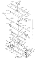
- an operation control device in accordance with the present invention is shown comprising a housing 1 , a control module 2 and a circuit module 3 .
- the housing 1 comprises a bottom cover shell 11 , a top cover shell 12 covered on the bottom cover shell 11 and an accommodation chamber 10 defined in between the bottom cover shell 11 and the top cover shell 12 .
- the bottom cover shell 11 comprises a plurality of upright retaining lugs 111 and posts 112 respectively symmetrically disposed near the two distal ends thereof, a plurality of spring seats 113 bilaterally disposed near the rear side and respectively disposed adjacent to the upright retaining lugs 111 , a plurality of spring holders 114 respectively disposed at a front side relative to the spring seats 113 , and a plurality of upright pivot pins 115 respectively disposed adjacent to the posts 112 .
- the top cover shell 12 comprises two locating holes 122 disposed near the two distal ends thereof, an elongated slot 121 connected between the two locating holes 122 in communication with the accommodation chamber 10 , a front opening 123 located on the middle near the front side thereof for the mounting of an operating device 124 , and a plurality of connection elements 125 respectively fastened to the posts 112 of the bottom over shell 11 .
- the control module 2 is accommodated in the accommodation chamber 10 of the housing 1 , comprising a carrier frame 21 , a movable operating device 22 carried on the carrier frame 21 and peripherally partially protruding over the elongated slot 121 of the top cover shell 12 of the housing 1 , and a plurality of spring members 213 respectively mounted in the spring seats 113 and stopped against the bottom wall of the carrier frame 21 to support the carrier frame 21 in a floating condition.
- the carrier frame 21 comprises two end lugs 211 respectively upwardly extended from the two distal ends thereof and respectively fastened to the locating holes 122 of the top cover shell 12 and protruding over the top side of the top cover shell 12 of the housing 1 for supporting the movable operating device 22 , two coupling hooks 212 respectively downwardly extended from the end lugs 211 and respectively coupled to the upright retaining lugs 111 of the bottom cover shell 11 of the housing 1 , a plurality of press portions 214 located on the front side thereof, and a plurality of bearing portions 215 respectively abutted against the press portion 214 .
- the movable operating device 22 comprises an elongated base member 221 that comprises a coupling hole 2210 axially disposed at each of two distal ends thereof and two rod members 2211 respectively mounted between the coupling hole 2210 on each of the distal ends of the elongated base member 221 and a retaining groove 2111 on each of the two end lugs 211 of the carrier frame 21 , a sleeve 222 sleeved onto the rod members 2211 and the elongated base member 221 , and two annular end caps 2222 respectively fastened to the two distal ends of the axial hole 2221 of the sleeve 222 and supported on the rod members 2211 for allowing the sleeve 222 to be rotated and axially slidably moved with the annular end caps 2222 relative to the elongated base member 221 and the rod members 2211 .
- the control module 2 further comprises an actuation member 23 , which comprises an actuation portion 231 located on the middle part of the front side thereof, two annular end blocks 232 respectively downwardly protruded from the two distal ends thereof and respectively capped on the spring holders 114 , a hook 2321 extended from each of the annular end blocks 232 and respectively hooked in a vertically extending hook hole 1141 on each of the spring holders 114 and a plurality of pivot holders 234 located on the bottom side thereof, two spring members 233 respectively mounted in between the spring holders 114 and the annular end blocks 232 to support the actuation member 23 in the bottom cover shell 11 in a floating condition, and a balance rod 235 pivotally mounted in the pivot holders 234 of the actuation member 23 .
- an actuation member 23 which comprises an actuation portion 231 located on the middle part of the front side thereof, two annular end blocks 232 respectively downwardly protruded from the two distal ends thereof and respectively capped on the spring holders 114 , a hook 23
- the circuit module 3 is accommodated in the accommodation chamber 10 inside the housing 1 at a front side relative to the control module 2 , comprising a circuit board 30 , a microprocessor 31 installed in the circuit board 30 , a rotation sensor module 32 mounted in the elongated base member 221 of the movable operating device 22 and electrically connected to the microprocessor 31 and adapted for sensing the amount and direction of rotation of the sleeve 222 , a plurality of control switches 33 electrically connected to the microprocessor 31 and operable by the operating device 124 and the actuation portion 231 of the actuation member 23 , two magnetic sensors 34 electrically connected to the microprocessor 31 and respectively disposed near the two distal ends of the movable operating device 22 and adapted for sensing the direction and amount of axial displacement of the movable operating device 22 in a non-contact manner and producing a corresponding signal, and a connection interface 35 electrically connected to the microprocessor 31 and electrically connectable to a communication port of an external electronic apparatus, for example
- the aforesaid magnetic sensors 34 each comprise a lever 341 , which has a pivot hole 3411 vertically located on a middle part thereof and pivotally coupled to one of the upright pivot pins 115 of the bottom cover shell 11 and a contact portion 3412 located on one end, namely, the rear end thereof and rested in one respective bearing portion 215 of the carrier frame 21 and pushable by the sleeve 222 by means of one respective annular end cap 2222 , a magnet 342 located on one side of an opposite end, namely, the front end of the lever 341 , a magnetic sensing element 343 located on one of the two distal ends of the circuit board 30 and electrically connected to the microprocessor 31 for sensing approach of the magnet 342 , and a return spring 3413 connected between the opposite side of the front end of the lever 341 and one of the two posts 112 of the bottom cover shell 11 for returning the lever 341 to its former position after the lever 341 having been biased.
- the housing 1 consists of the bottom cover shell 11 and the top cover shell 12 .
- the housing 1 can be a single-piece member having an accommodation chamber 10 defined therein for accommodating the control module 2 and the circuit module 3 .
- the rod members 2211 of the movable operating device 22 can be round rods, oval rods, or any other shape of rods that facilitates rotating and sliding the sleeve 222 relative to the rotation sensor module 32 in the elongated base member 221 .
- the rod members 2211 are made of a self-lubricating material, for example, POM (polyoxymethylene) or PTFE (polytetrafluoroethylene).
- the rotation sensor module 32 comprises a light transmitter (not shown) adapted for emitting a predetermined light onto the inside wall of the sleeve 222 , a lens (not shown), and a light receiver adapted for receiving the light reflected by the inside wall of the sleeve 222 through the lens and outputting a corresponding signal to the microprocessor 31 for computing.
- the rotation sensor module 32 will output a signal to the microprocessor 31 that is indicative of the amount and direction of the rotation of the sleeve 222 .
- the inside wall of the sleeve 222 can be colored, or processed to provide recessed portions or raised portions, facilitating mapping and image recognition.
- the microprocessor 31 After computing of the sensed signal from the rotation sensor module 32 by the microprocessor 31 , the microprocessor 31 outputs a control signal through the connection interface 35 to the external electronic apparatus to control the movement of the cursor on the display screen of the external electronic apparatus.
- the sleeve 222 can be made of a meshed fabric, nonwoven cloth, plastic, rubber or leather, and peripherally marked with a laser mark, or printed or coated with a textual or graphic design.
- the operation control device can be used in or with a computer, notebook computer, mobile telephone or any of a variety of other electronic apparatus.
- the connection interface 35 is electrically connected to a communication port of the external electronic apparatus by a wired (or wireless) connection method.
- the user can rest the wrists of the hands on a wrist pad (not shown) in front of the front opening 123 of the top cover shell 12 of the housing 1 , and rotate the sleeve 222 on the elongated base member 221 with the fingers.
- the rotation sensor module 32 senses the direction and amount of the rotation of the sleeve 222 , and outputs a corresponding signal to the microprocessor 31 , enabling the microprocessor 31 to output a corresponding control signal through the connection interface 35 to the external electronic apparatus to control the movement of the cursor on the display screen of the external electronic apparatus in Y-axis direction (up/down direction).
- the annular end caps 2222 support the sleeve 222 on the rod members 2211 , enabling the sleeve 222 to be rotated transversely forwards/backwards and moved axially leftwards/rightwards on the rod members 2211 relative to the elongated base member 221 and the rotation sensor module 32 without causing much friction.
- the user can operate the movable operating device 22 stably and comfortably.
- the rotation sensor module 32 is mounted in the elongated base member 221 between the rod members 2211 and surrounded by the sleeve 222 . Therefore, the sleeve 222 protects the rotation sensor module 32 against outside dust and micro particles and keeps the rotation sensor module 32 from sight, assuring sensing accuracy of the rotation sensor module 32 and saving the surface space of the circuit board 30 .
- the invention has small-sized and nice-looking characteristics.
- the length of the sleeve 222 is shorter than the length of the elongated slot 121 of the top cover shell 12 of the housing 1 , and the rotation sensor module 32 is surrounded by the sleeve 222 .
- the user can slide the sleeve 222 axially leftwards or rightwards in the elongated slot 121 along the rod members 2211 .
- one annular end cap 2222 When moving the sleeve 222 axially in the elongated slot 121 toward one locating hole 122 , one annular end cap 2222 is forced against the contact portion 3412 of the lever 341 of one magnetic sensor 34 to bias the lever 341 in one direction, moving the magnet 342 of the respective magnetic sensor 34 toward the associating magnetic sensing element 343 at the circuit board 30 .
- the magnetic sensing element 343 senses the strength of the magnetic field induced by the magnet 342 that is indicative of the distance of axial displacement of the sleeve 222 , and outputs a corresponding signal to the microprocessor 31 , enabling the microprocessor 31 to output a corresponding control signal through the connection interface 35 to the external electronic apparatus to control the movement of the cursor on the display screen of the external electronic apparatus in X-axis direction (left/right direction).
- the magnetic sensing element 343 can be a Hall IC or MR (magneto-resistive) sensor. Subject to the non-contact sensing operation of the magnetic sensors 34 , the invention effectively and accurately senses the amount and direction of the displacement of the sleeve 222 and eliminates the drawbacks of mechanical fatigue and contact error of conventional contact switch designs.
- the coupling hooks 212 are lowered with the carrier frame 21 relative to the upright retaining lugs 111 of the bottom cover shells 11 of the housing 1 , and the press portions 214 are lowered with the carrier frame 21 to force the actuation member 23 downwardly, causing the respective hooks 2321 to be moved downwardly in the respective vertically extending hook holes 1141 of the respective spring holders 114 .
- the spring members 213 are compressed between the respective spring seats 113 and the carrier frame 21
- the spring members 233 are compressed between the respective spring holders 114 and the annular end blocks 232 of the actuation member 23 .
- the actuation portion 231 of the actuation member 23 is forced to trigger one control switch 33 on the circuit board 30 of the circuit module 3 , producing a cursor clicking effect.
- the user can press down, rotate or slide the sleeve 22 to drag or click the cursor.
- the spring members 213 ; 233 immediately return the carrier frame 21 and the actuation member 23 upwardly to their former position,
- the pressure may be applied to the sleeve 22 at a location deviated from the midpoint of the sleeve 22 , causing the sleeve 22 , the carrier frame 21 and the actuation member 23 to tilt.
- This problem is eliminated subject to the functioning of the balance rod 235.
- the balance rod 235 is pivotally coupled to the pivot holders 234 of the actuation member 23 .
- the balance rod 235 is biased to keep the carrier frame 21 and the actuation member 23 in balance.
- the aforesaid operating device 124 can be a button, roller, rolling ball, or any finger-operable member operable by the user to trigger one control switch 33 of the circuit module 3 in controlling the cursor to perform a specific input mode.
- FIGS. 1 ⁇ 8 A prototype of operation control device has been constructed with the features of FIGS. 1 ⁇ 8 .
- the operation control device functions smoothly to provide all of the features disclosed earlier.
Landscapes
- Engineering & Computer Science (AREA)
- General Engineering & Computer Science (AREA)
- Theoretical Computer Science (AREA)
- Human Computer Interaction (AREA)
- Physics & Mathematics (AREA)
- General Physics & Mathematics (AREA)
- Position Input By Displaying (AREA)
- Automatic Assembly (AREA)
- Accommodation For Nursing Or Treatment Tables (AREA)
- Switches With Compound Operations (AREA)
Applications Claiming Priority (1)
| Application Number | Priority Date | Filing Date | Title |
|---|---|---|---|
| TW099225383U TWM407435U (en) | 2010-12-29 | 2010-12-29 | Manipulation control device |
Publications (1)
| Publication Number | Publication Date |
|---|---|
| EP2472359A2 true EP2472359A2 (de) | 2012-07-04 |
Family
ID=45081210
Family Applications (2)
| Application Number | Title | Priority Date | Filing Date |
|---|---|---|---|
| EP11165873A Withdrawn EP2472359A2 (de) | 2010-12-29 | 2011-05-12 | Betriebssteuervorrichtung |
| EP11195920.1A Withdrawn EP2472360A3 (de) | 2010-12-29 | 2011-12-28 | Steuervorrichtung |
Family Applications After (1)
| Application Number | Title | Priority Date | Filing Date |
|---|---|---|---|
| EP11195920.1A Withdrawn EP2472360A3 (de) | 2010-12-29 | 2011-12-28 | Steuervorrichtung |
Country Status (5)
| Country | Link |
|---|---|
| US (1) | US8314771B2 (de) |
| EP (2) | EP2472359A2 (de) |
| JP (1) | JP3174253U (de) |
| CA (1) | CA2762803A1 (de) |
| TW (1) | TWM407435U (de) |
Cited By (3)
| Publication number | Priority date | Publication date | Assignee | Title |
|---|---|---|---|---|
| WO2014070061A1 (en) * | 2012-11-02 | 2014-05-08 | Drougge Gunnar | Coordinate device with pressing down function |
| CN104883531A (zh) * | 2015-05-14 | 2015-09-02 | 无锡华海天和信息科技有限公司 | 一种视频通话中回音消除的实现方法 |
| EP2530558A3 (de) * | 2011-08-01 | 2015-09-02 | Ergzon Co., Ltd. | Cursorsteuerungsvorrichtung |
Families Citing this family (4)
| Publication number | Priority date | Publication date | Assignee | Title |
|---|---|---|---|---|
| US9024873B2 (en) * | 2010-05-04 | 2015-05-05 | Chen-Min Hung | Control device |
| EP2997453B1 (de) * | 2013-05-17 | 2020-10-21 | SeeScan, Inc. | Benutzeroberflächenvorrichtungen |
| US10379637B2 (en) * | 2015-01-30 | 2019-08-13 | Logitech Europe S.A. | Rotational element enabling touch-like gestures |
| EP4584669A1 (de) * | 2022-09-09 | 2025-07-16 | Contour Design Nordic A/S | Zeigevorrichtung mit flexibler hülse |
Family Cites Families (11)
| Publication number | Priority date | Publication date | Assignee | Title |
|---|---|---|---|---|
| US6211860B1 (en) * | 1994-07-06 | 2001-04-03 | Hewlett-Packard Company | Pressure sensitive electronic device |
| US6034670A (en) * | 1996-09-30 | 2000-03-07 | Chen; Mei Yun | Cursor positioning apparatus |
| JP2000132331A (ja) * | 1998-08-21 | 2000-05-12 | Shinsuke Hamaji | ロ―ラ―スライド式ポインティングデバイス |
| US6809724B1 (en) * | 2000-01-18 | 2004-10-26 | Seiko Epson Corporation | Display apparatus and portable information processing apparatus |
| US7903087B2 (en) * | 2006-02-13 | 2011-03-08 | Research In Motion Limited | Method for facilitating navigation and selection functionalities of a trackball incorporated upon a wireless handheld communication device |
| US7770118B2 (en) * | 2006-02-13 | 2010-08-03 | Research In Motion Limited | Navigation tool with audible feedback on a handheld communication device having a full alphabetic keyboard |
| JP4767200B2 (ja) * | 2007-03-08 | 2011-09-07 | 任天堂株式会社 | 情報選択装置および情報選択プログラム |
| US8866743B2 (en) * | 2007-07-16 | 2014-10-21 | Blackberry Limited | Navigational tool with drag-based tactile feedback on a handheld wireless communication device |
| TWM363635U (en) * | 2009-03-04 | 2009-08-21 | Chance Steel Mold Co Ltd | Manipulation control device |
| EP2228110B1 (de) * | 2009-03-09 | 2017-08-30 | Nintendo Co., Ltd. | Gerät zur Koordinatenberechnung und Speichermedium mit dort gespeichertem Koordinatenberechnungsprogramm |
| US8441438B2 (en) * | 2010-01-06 | 2013-05-14 | Cywee Group Limited | 3D pointing device and method for compensating movement thereof |
-
2010
- 2010-12-29 TW TW099225383U patent/TWM407435U/zh not_active IP Right Cessation
-
2011
- 2011-04-20 US US13/064,828 patent/US8314771B2/en not_active Expired - Fee Related
- 2011-05-12 EP EP11165873A patent/EP2472359A2/de not_active Withdrawn
- 2011-12-28 JP JP2011007765U patent/JP3174253U/ja not_active Expired - Fee Related
- 2011-12-28 CA CA2762803A patent/CA2762803A1/en not_active Abandoned
- 2011-12-28 EP EP11195920.1A patent/EP2472360A3/de not_active Withdrawn
Non-Patent Citations (1)
| Title |
|---|
| None |
Cited By (4)
| Publication number | Priority date | Publication date | Assignee | Title |
|---|---|---|---|---|
| EP2530558A3 (de) * | 2011-08-01 | 2015-09-02 | Ergzon Co., Ltd. | Cursorsteuerungsvorrichtung |
| EP2555086A3 (de) * | 2011-08-01 | 2015-09-02 | Ergzon Co., Ltd. | Hülse und Steuerungsvorrichtung mit einer solchen Hülse |
| WO2014070061A1 (en) * | 2012-11-02 | 2014-05-08 | Drougge Gunnar | Coordinate device with pressing down function |
| CN104883531A (zh) * | 2015-05-14 | 2015-09-02 | 无锡华海天和信息科技有限公司 | 一种视频通话中回音消除的实现方法 |
Also Published As
| Publication number | Publication date |
|---|---|
| EP2472360A2 (de) | 2012-07-04 |
| EP2472360A3 (de) | 2014-10-01 |
| CA2762803A1 (en) | 2012-06-29 |
| TWM407435U (en) | 2011-07-11 |
| US8314771B2 (en) | 2012-11-20 |
| US20120169595A1 (en) | 2012-07-05 |
| JP3174253U (ja) | 2012-03-08 |
Similar Documents
| Publication | Publication Date | Title |
|---|---|---|
| US9048044B2 (en) | Cursor control device | |
| US8314771B2 (en) | Operation control device | |
| US6809722B2 (en) | Hand-held mobile mouse | |
| US6580420B1 (en) | Convertible computer input device | |
| US9024873B2 (en) | Control device | |
| US8184095B2 (en) | Control device | |
| CN101681206B (zh) | 鼠标设备 | |
| JP5702401B2 (ja) | 内部センサ・ベースのポインティングデバイス | |
| US6940487B2 (en) | Input unit and information processing unit | |
| JPH0651865A (ja) | ポータブルコンピュータシステム、コンピュータシステムのキーボードおよびコンピュータシステムのポインティング装置 | |
| US20110037693A1 (en) | Cursor control device | |
| US20050093837A1 (en) | Electronic pen-like input device | |
| US20120162071A1 (en) | Control device | |
| US20120026091A1 (en) | Pen-type mouse | |
| US20060164392A1 (en) | Integrated mouse and the keyboard device | |
| US7808482B2 (en) | Slim mouse | |
| US20050110779A1 (en) | Pen-like mouse device | |
| EP2605110A2 (de) | Steuervorrichtung | |
| EP2431843A2 (de) | Steuervorrichtung | |
| US20120062458A1 (en) | Control device | |
| JP2005522749A (ja) | 電子ペン方式入力デバイス | |
| JPH04319722A (ja) | 入力装置 |
Legal Events
| Date | Code | Title | Description |
|---|---|---|---|
| AK | Designated contracting states |
Kind code of ref document: A2 Designated state(s): AL AT BE BG CH CY CZ DE DK EE ES FI FR GB GR HR HU IE IS IT LI LT LU LV MC MK MT NL NO PL PT RO RS SE SI SK SM TR |
|
| AX | Request for extension of the european patent |
Extension state: BA ME |
|
| PUAI | Public reference made under article 153(3) epc to a published international application that has entered the european phase |
Free format text: ORIGINAL CODE: 0009012 |
|
| RIC1 | Information provided on ipc code assigned before grant |
Ipc: G06F 3/033 20130101AFI20140826BHEP Ipc: G06F 3/0362 20130101ALI20140826BHEP Ipc: H01H 25/00 20060101ALI20140826BHEP Ipc: G06F 3/0354 20130101ALI20140826BHEP |
|
| STAA | Information on the status of an ep patent application or granted ep patent |
Free format text: STATUS: THE APPLICATION IS DEEMED TO BE WITHDRAWN |
|
| 18D | Application deemed to be withdrawn |
Effective date: 20141202 |