EP2472081A2 - Moteur à turbine à gaz à cycle variable - Google Patents
Moteur à turbine à gaz à cycle variable Download PDFInfo
- Publication number
- EP2472081A2 EP2472081A2 EP11010294A EP11010294A EP2472081A2 EP 2472081 A2 EP2472081 A2 EP 2472081A2 EP 11010294 A EP11010294 A EP 11010294A EP 11010294 A EP11010294 A EP 11010294A EP 2472081 A2 EP2472081 A2 EP 2472081A2
- Authority
- EP
- European Patent Office
- Prior art keywords
- turbine
- compressor
- gas flow
- variable cycle
- engine
- Prior art date
- Legal status (The legal status is an assumption and is not a legal conclusion. Google has not performed a legal analysis and makes no representation as to the accuracy of the status listed.)
- Granted
Links
- 238000004891 communication Methods 0.000 claims description 21
- 239000012530 fluid Substances 0.000 claims description 17
- 238000011144 upstream manufacturing Methods 0.000 claims description 3
- 239000007789 gas Substances 0.000 description 61
- 238000002485 combustion reaction Methods 0.000 description 14
- 230000008901 benefit Effects 0.000 description 3
- 239000000446 fuel Substances 0.000 description 3
- 238000012986 modification Methods 0.000 description 3
- 230000004048 modification Effects 0.000 description 3
- 238000005474 detonation Methods 0.000 description 2
- 239000000284 extract Substances 0.000 description 2
- RZVHIXYEVGDQDX-UHFFFAOYSA-N 9,10-anthraquinone Chemical compound C1=CC=C2C(=O)C3=CC=CC=C3C(=O)C2=C1 RZVHIXYEVGDQDX-UHFFFAOYSA-N 0.000 description 1
- 230000004075 alteration Effects 0.000 description 1
- 230000003416 augmentation Effects 0.000 description 1
- 238000006243 chemical reaction Methods 0.000 description 1
- 238000004200 deflagration Methods 0.000 description 1
- 238000005516 engineering process Methods 0.000 description 1
- 238000000605 extraction Methods 0.000 description 1
- RLQJEEJISHYWON-UHFFFAOYSA-N flonicamid Chemical compound FC(F)(F)C1=CC=NC=C1C(=O)NCC#N RLQJEEJISHYWON-UHFFFAOYSA-N 0.000 description 1
- 230000007246 mechanism Effects 0.000 description 1
- 238000000034 method Methods 0.000 description 1
- 230000003287 optical effect Effects 0.000 description 1
- 230000001737 promoting effect Effects 0.000 description 1
- 230000009467 reduction Effects 0.000 description 1
Images

Classifications
-
- F—MECHANICAL ENGINEERING; LIGHTING; HEATING; WEAPONS; BLASTING
- F02—COMBUSTION ENGINES; HOT-GAS OR COMBUSTION-PRODUCT ENGINE PLANTS
- F02C—GAS-TURBINE PLANTS; AIR INTAKES FOR JET-PROPULSION PLANTS; CONTROLLING FUEL SUPPLY IN AIR-BREATHING JET-PROPULSION PLANTS
- F02C1/00—Gas-turbine plants characterised by the use of hot gases or unheated pressurised gases, as the working fluid
- F02C1/007—Gas-turbine plants characterised by the use of hot gases or unheated pressurised gases, as the working fluid combination of cycles
-
- F—MECHANICAL ENGINEERING; LIGHTING; HEATING; WEAPONS; BLASTING
- F02—COMBUSTION ENGINES; HOT-GAS OR COMBUSTION-PRODUCT ENGINE PLANTS
- F02C—GAS-TURBINE PLANTS; AIR INTAKES FOR JET-PROPULSION PLANTS; CONTROLLING FUEL SUPPLY IN AIR-BREATHING JET-PROPULSION PLANTS
- F02C3/00—Gas-turbine plants characterised by the use of combustion products as the working fluid
- F02C3/04—Gas-turbine plants characterised by the use of combustion products as the working fluid having a turbine driving a compressor
- F02C3/107—Gas-turbine plants characterised by the use of combustion products as the working fluid having a turbine driving a compressor with two or more rotors connected by power transmission
-
- F—MECHANICAL ENGINEERING; LIGHTING; HEATING; WEAPONS; BLASTING
- F02—COMBUSTION ENGINES; HOT-GAS OR COMBUSTION-PRODUCT ENGINE PLANTS
- F02C—GAS-TURBINE PLANTS; AIR INTAKES FOR JET-PROPULSION PLANTS; CONTROLLING FUEL SUPPLY IN AIR-BREATHING JET-PROPULSION PLANTS
- F02C3/00—Gas-turbine plants characterised by the use of combustion products as the working fluid
- F02C3/04—Gas-turbine plants characterised by the use of combustion products as the working fluid having a turbine driving a compressor
- F02C3/13—Gas-turbine plants characterised by the use of combustion products as the working fluid having a turbine driving a compressor having variable working fluid interconnections between turbines or compressors or stages of different rotors
-
- F—MECHANICAL ENGINEERING; LIGHTING; HEATING; WEAPONS; BLASTING
- F02—COMBUSTION ENGINES; HOT-GAS OR COMBUSTION-PRODUCT ENGINE PLANTS
- F02C—GAS-TURBINE PLANTS; AIR INTAKES FOR JET-PROPULSION PLANTS; CONTROLLING FUEL SUPPLY IN AIR-BREATHING JET-PROPULSION PLANTS
- F02C7/00—Features, components parts, details or accessories, not provided for in, or of interest apart form groups F02C1/00 - F02C6/00; Air intakes for jet-propulsion plants
- F02C7/32—Arrangement, mounting, or driving, of auxiliaries
-
- F—MECHANICAL ENGINEERING; LIGHTING; HEATING; WEAPONS; BLASTING
- F02—COMBUSTION ENGINES; HOT-GAS OR COMBUSTION-PRODUCT ENGINE PLANTS
- F02C—GAS-TURBINE PLANTS; AIR INTAKES FOR JET-PROPULSION PLANTS; CONTROLLING FUEL SUPPLY IN AIR-BREATHING JET-PROPULSION PLANTS
- F02C9/00—Controlling gas-turbine plants; Controlling fuel supply in air- breathing jet-propulsion plants
- F02C9/16—Control of working fluid flow
- F02C9/18—Control of working fluid flow by bleeding, bypassing or acting on variable working fluid interconnections between turbines or compressors or their stages
-
- F—MECHANICAL ENGINEERING; LIGHTING; HEATING; WEAPONS; BLASTING
- F02—COMBUSTION ENGINES; HOT-GAS OR COMBUSTION-PRODUCT ENGINE PLANTS
- F02K—JET-PROPULSION PLANTS
- F02K3/00—Plants including a gas turbine driving a compressor or a ducted fan
- F02K3/02—Plants including a gas turbine driving a compressor or a ducted fan in which part of the working fluid by-passes the turbine and combustion chamber
- F02K3/025—Plants including a gas turbine driving a compressor or a ducted fan in which part of the working fluid by-passes the turbine and combustion chamber the by-pass flow being at least partly used to create an independent thrust component
-
- F—MECHANICAL ENGINEERING; LIGHTING; HEATING; WEAPONS; BLASTING
- F02—COMBUSTION ENGINES; HOT-GAS OR COMBUSTION-PRODUCT ENGINE PLANTS
- F02K—JET-PROPULSION PLANTS
- F02K3/00—Plants including a gas turbine driving a compressor or a ducted fan
- F02K3/02—Plants including a gas turbine driving a compressor or a ducted fan in which part of the working fluid by-passes the turbine and combustion chamber
- F02K3/04—Plants including a gas turbine driving a compressor or a ducted fan in which part of the working fluid by-passes the turbine and combustion chamber the plant including ducted fans, i.e. fans with high volume, low pressure outputs, for augmenting the jet thrust, e.g. of double-flow type
- F02K3/075—Plants including a gas turbine driving a compressor or a ducted fan in which part of the working fluid by-passes the turbine and combustion chamber the plant including ducted fans, i.e. fans with high volume, low pressure outputs, for augmenting the jet thrust, e.g. of double-flow type controlling flow ratio between flows
Definitions
- the present invention relates to gas turbine engines, and more particularly, variable cycle gas turbine engines.
- Variable cycle gas turbine engines remain an area of interest. Some existing systems have various shortcomings, drawbacks, and disadvantages relative to certain applications. Accordingly, there remains a need for further contributions in this area of technology.
- One embodiment of the present invention is a unique variable cycle gas turbine engine.
- Other embodiments include apparatuses, systems, devices, hardware, methods, and combinations for variable cycle gas turbine engines. Further embodiments, forms, features, aspects, benefits, and advantages of the present application will become apparent from the description and figures provided herewith.
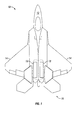
- Aircraft 10 includes a fuselage 12, wings 14, an empennage 16 and two propulsion systems 18.
- aircraft 10 is a twin engine military turbofan aircraft.
- aircraft 10 may be any fixed-wing aircraft, including turbofan aircraft, turbojet aircraft and turboprop aircraft.
- aircraft 10 may be a rotary-wing aircraft or a combination rotary-wing/fixed-wing aircraft.
- aircraft 10 may have a single propulsion engine or a plurality of propulsion engines.
- aircraft 10 may employ any number of wings 14.
- Empennage 16 may employ a single or multiple flight control surfaces.
- Propulsion system 18 includes a gas turbine engine 20 as a main engine, i.e., a main propulsion engine, which includes an auxiliary turbine system 22.
- Engine 20 is a primary propulsion engine that provides thrust for flight operations of aircraft 10.
- engine 20 is a two-spool engine having a high pressure (HP) spool 24 and a low pressure (LP) spool 26.
- HP high pressure
- LP low pressure
- engine 20 may include three or more spools, for example, and may include an intermediate pressure (IP) spool and/or other spools.
- IP intermediate pressure
- engine 20 is a turbofan engine, wherein LP spool 26 is operative to drive a propulsor 28 in the form of a turbofan (fan) system, which may be referred to as a turbofan, a fan or a fan system.
- engine 20 may be a turboprop engine, wherein LP spool 26 powers a propulsor 28 in the form of a propeller system (not shown), e.g., via a reduction gearbox (not shown).
- propulsor 28 may take other forms, such as a helicopter rotor or tilt-wing aircraft rotor or a propfan.
- two propulsion systems 18 are coupled to fuselage 12 of aircraft 10.
- one or more propulsion systems 18 may be coupled to other portions of aircraft 10.
- one or more propulsion systems 18 may be coupled to each wing 14 and/or empennage 16 in addition to or in place of fuselage-mounted propulsion systems 18.
- engine 20 includes, in addition to auxiliary turbine system 22 and fan system 28, an accessory gearbox 23, a bypass duct 30, a compressor system 32 as part of HP spool 24, a diffuser 34, a combustion system 36, a high pressure (HP) turbine 38 as part of HP spool 24, a low pressure (LP) turbine 40 as part of LP spool 26, a nozzle 42A, and a nozzle 42B.
- Accessory gearbox 23 is coupled to HP spool 24 and compressor 32 via conventional means, e.g., a bevel gear set and shafting 25.
- accessory gearbox 23 may be coupled to HP spool 24 and/or LP spool 26 via other mechanical arrangements.
- compressor 32 is a variable compressor.
- compressor 32 may not be a variable compressor.
- compressor 32 is a variable geometry compressor.
- compressor 32 may be other types of variable compressors that may or may not employ variable geometry, e.g., including geared compressors that are configured to operate at more than one speed relative to a given shaft input speed.
- combustion system 36 includes a combustion liner (not shown) that contains a continuous combustion process.
- combustion system 36 may take other forms, and may be, for example, a wave rotor combustion system, a rotary valve combustion system, a pulse detonation combustion system and/or a slinger combustion system, and may employ deflagration and/or detonation combustion processes.
- Fan system 28 includes a fan rotor system 48 driven by LP spool 26.
- fan rotor system 48 includes one or more rotors (not shown) that are powered by LP turbine 40, which may operate at the same or different rotational speeds.
- Fan system 28 may include one or more stages of vanes (not shown).
- Bypass duct 30 is operative to transmit a bypass flow generated by fan system 28 around the core of engine 20.
- Compressor 32 includes a compressor rotor system 50.
- compressor rotor system 50 includes one or more rotors (not shown) that are powered by HP turbine 38.
- HP turbine 38 includes a turbine rotor system 52.
- turbine rotor system 52 includes one or more rotors (not shown) operative to drive compressor rotor system 50.
- Turbine rotor system 52 is drivingly coupled to compressor rotor system 50 via a shafting system 54.
- LP turbine 40 includes a turbine rotor system 56.
- turbine rotor system 56 includes one or more rotors (not shown) operative to drive fan rotor system 48.
- Turbine rotor system 56 is drivingly coupled to fan rotor system 48 via a shafting system 58.
- shafting systems 54 and 58 include a plurality of shafts that may rotate at the same or different speeds and directions. In some embodiments, only a single shaft may be employed in one or both of shafting systems 54 and 58.
- LP turbine 40 is operative to discharge the engine 20 core gas flow to nozzle 42A.
- air is drawn into the inlet of fan system 28 and pressurized by fan rotor system 48.
- Some of the air pressurized by fan rotor system 48 is directed into compressor 32 as core gas flow, and some of the pressurized air is directed into bypass duct 30 as bypass flow.
- Compressor 32 further pressurizes the core gas flow received therein from fan system 28, which is then discharged into diffuser 34.
- Diffuser 34 reduces the velocity of the pressurized air, and directs the diffused core gas flow into combustion system 36. Fuel is mixed with the pressurized air in combustion system 36, which is then combusted.
- the core gas flow in the form of hot gases exiting combustion system 36, are directed into HP and LP turbines 38 and 40, e.g., sequentially, which extract energy in the form of mechanical shaft power to drive compressor 32 and fan 28 via respective shafting systems 54 and 58.
- the engine 20 core flow is discharged through nozzle 42A
- the bypass flow is discharged through nozzle 42B.
- other nozzle arrangements may be employed, e.g., a common nozzle for core and bypass flow; a nozzle for core flow, but no nozzle for bypass flow; or another nozzle arrangement.
- engine 20 product peak thrust output during aircraft 10 takeoff, and during some aircraft 10 maneuvering operations.
- engine 20 operate at high efficiency during cruise conditions, including supercruise conditions, i.e., supersonic cruise without the use of thrust augmentation (e.g., afterburners).
- thrust augmentation e.g., afterburners
- a fixed geometry gas turbine engine sized for takeoff thrust conditions yields a greater than ideal specific fuel consumption during cruise conditions because the engine is running at an "off-design" point during cruise conditions.
- a fixed geometry gas turbine sized for peak efficiency during cruise conditions may have insufficient thrust for desirable takeoff and maneuver performance.
- engine 20 is configured as a variable cycle gas turbine engine.
- engine 20 employs auxiliary turbine system 22 for selectively expanding and contracting the turbine flow capacity of engine 20.
- compressor 32 may be variable, e.g., a variable geometry compressor, which in conjunction with auxiliary turbine system 22 further enhances the cycle variability of engine 20.
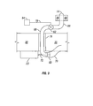
- auxiliary turbine system 22 includes an auxiliary turbine 60, a valve 62, a controller 64, inlet ducting 66 and 68, and exhaust ducting 70.
- auxiliary turbine 60 is mechanically coupled to accessory gearbox 23 via a shaft 72, and is coupled to compressor 32 via accessory gearbox 23.
- auxiliary turbine 60 may be coupled to compressor 32 or one or more other HP spool 24 components, e.g., shafting system 54, via other mechanical arrangements.
- Inlet ducting 66 is coupled to a plenum 74 at one end, and is coupled to valve 62 at the other end.
- Plenum 74 is disposed between the outlet of HP turbine 38 and the inlet of LP turbine 40, and is operative to receive a portion of the core gas flow exiting HP turbine 38 for use by auxiliary turbine 60.
- the portion of core gas flow for use by auxiliary turbine 60 may be obtained from one or more other turbine stages, in addition to or in place of the HP turbine 38 outlet.
- the portion of core gas flow for use by auxiliary turbine 60 may be obtained via other arrangements, which may or may not employ the use of a plenum for the extraction of the portion of the core gas flow for auxiliary turbine 60, depending upon the needs of the particular application.
- Inlet ducting 68 is coupled to valve 62 at one end, and to the inlet of auxiliary turbine 60 at the other end. In one form, portions of inlet ducting 68 that pass through bypass duct 30 are disposed within an aerodynamic strut 76 in order to minimize losses. In other embodiments, other arrangements may be employed.
- Exhaust ducting 70 is coupled to the outlet of auxiliary turbine 60 at one end, and is configured to direct the exhaust from auxiliary turbine 60 into bypass duct 30 at the other end for conversion to thrust, e.g., via nozzle 42B.
- auxiliary turbine system 22 may be configured to discharge the auxiliary turbine 60 exhaust flow to other locations, for example and without limitation, into nozzle 42A or overboard engine 20.
- inlet ducting 66 inlet ducting 68 and exhaust ducting 70 as set forth herein
- other embodiments may employ other arrangements to channel flow to and from valve 62 and auxiliary turbine 60.
- auxiliary turbine 60 may be disposed outside of bypass duct 30, in other embodiments, auxiliary turbine 60 may be disposed in other locations, including radially inward of bypass duct 30, inside bypass duct 30, or upstream or downstream of bypass duct 30.
- Valve 62 is configured to regulate the portion of the core gas flow that is received by auxiliary turbine 60.
- valve 62 is configured to modulate the portion of the core gas flow received by auxiliary turbine 60 between a minimum flow amount and a maximum flow amount in accordance with the needs of the particular application.
- Valve 62 is also configured to close to prevent flow to auxiliary turbine 60.
- Valve 62 is controlled by controller 64 to selectively allow or disallow flow through valve 62.
- Valve 62 may take any suitable form, and may be, for example and without limitation, a butterfly valve, a gate valve, a poppet valve or any other suitable valve type.
- Valve 62 is actuated by an actuation mechanism (not shown) under the direction of controller 64.
- Controller 64 is communicatively coupled to valve 62 via a communications link 78.
- Communications link 78 may take any suitable form, and may be, for example, a wired and/or wireless and/or optical link capable of transmitting control signals to valve 62.
- valve 62 may provide feedback information to controller 64 indicative of valve position, in which case communications link 78 is also configured to transmit feedback signals to controller 64 from valve 62.
- communications link 78 may also be configured to provide electrical power for actuating valve 62.
- Controller 64 is configured to execute program instructions to control valve 62 to selectively prevent or allow flow to auxiliary turbine 60, and to regulate the flow rate to a desired level during engine 20 operations where such flow is desired.
- the flow regulation, including starting and stopping flow to auxiliary turbine 60 may be based on, for example and without limitation, one or more lookup tables and/or rate schedules, and/or may be based on, for example and without limitation, sensed and/or calculated engine 20 parameters, engine 20 inlet conditions, aircraft 10 speed and/or power lever angle.
- controller 64 is microprocessor based and the program instructions are in the form of software stored in a memory (not shown). However, it is alternatively contemplated that controller 64 and the program instructions may be in the form of any combination of software, firmware and hardware, including state machines, and may reflect the output of discreet devices and/or integrated circuits, which may be co-located at a particular location or distributed across more than one location, including any digital and/or analog devices configured to achieve the same or similar results as a processor-based controller executing software or firmware based instructions. In other embodiments, controller 64 may not be configured with the level of functionality associated with a processor-based controller, but rather may be a simple controller configuration. In one form, controller 64 is a gas turbine engine controller, such as a full authority digital electronic control (FADEC) unit. In other embodiments, controller 64 may take any suitable form, and in some embodiments may be a dedicated controller for operating valve 62.
- FADEC full authority digital electronic control
- auxiliary turbine system 22 to expand turbine flow capacity by opening valve 62 to allow a portion of core gas flow to flow through auxiliary turbine 60.
- Auxiliary turbine 60 extracts power from the gas flow and transmits the power via accessory gearbox 23 to compressor 32, thereby increasing the output of compressor 32, and hence engine 20.
- the exhaust gas from auxiliary turbine 60 is directed into bypass duct 30, from where it will contribute to the thrust output of engine 20.
- controller 64 may command valve 62 to open fully, thereby providing a maximum flow to auxiliary turbine 20, yielding a higher takeoff power output by engine 20 than a similar engine not equipped with auxiliary turbine system 22.
- valve 62 opens may vary with conditions, for example and without limitation, ambient/inlet conditions.
- controller 64 may command valve 62 to open partially or fully, e.g., depending operating conditions and/or pilot input.
- controller 64 may command valve 62 to close fully, thereby contracting the turbine flow capacity of engine 20, which may result in increased fuel efficiency, as engine 20 is effectively operating closer to design point at the cruise power condition.
- Embodiments of the present invention include a variable cycle gas turbine engine, comprising: a compressor configured to compress a core gas flow; a combustor in fluid communication with the compressor and configured to combust the core gas flow; a primary turbine drivingly coupled to the compressor and configured to receive the core gas flow, wherein the primary turbine is configured to drive the compressor; an auxiliary turbine drivingly coupled to the compressor; and a valve configured to selectively direct a portion of the core gas flow to the auxiliary turbine, wherein the auxiliary turbine is configured to extract power from the portion of the core gas flow and supply the power to the compressor when the valve is open.
- valve is in fluid communication with the primary turbine and operative to receive the portion of the core gas flow from the primary turbine.
- valve is configured to modulate the portion of the core gas flow between a minimum flow amount and a maximum flow amount.
- valve is configured to close to prevent flow to the auxiliary turbine.
- valve is operative to open during a takeoff power condition of the engine.
- valve is operative to close during a cruise power condition of the engine.
- the compressor is a variable compressor.
- variable cycle gas turbine engine further comprises a fan and a fan bypass duct in fluid communication with the fan, wherein variable cycle gas turbine engine is configured to direct the exhaust of the auxiliary turbine into the fan bypass duct.
- variable cycle gas turbine engine further comprises an accessory gearbox coupled to the compressor, wherein the auxiliary turbine is drivingly coupled to the compressor via the accessory gearbox.
- Embodiments of the present invention include a variable cycle gas turbine engine, comprising: a compressor configured to compress a core gas flow; a combustor in fluid communication with the compressor and configured to combust the core gas flow; a primary turbine drivingly coupled to the compressor and configured to receive the core gas flow, wherein the primary turbine is configured to drive the compressor; and an auxiliary turbine system having an auxiliary turbine drivingly coupled to the compressor, wherein the auxiliary turbine system is configured to selectively receive a portion of the core gas flow; generate shaft power using the portion of the core gas flow; and supply the shaft power to the compressor.
- the auxiliary turbine system includes a valve configured to selectively direct a portion of the core gas flow to the auxiliary turbine.
- the primary turbine is a high pressure turbine; and wherein the valve is in fluid communication with the discharge of the high pressure turbine, and is operative to receive the portion of the core gas flow from the discharge of the high pressure turbine.
- valve is configured to modulate the portion of the core gas flow between a minimum flow amount and a maximum flow amount.
- variable cycle gas turbine engine further comprises a low pressure turbine; a fan driven by the low pressure turbine; and a fan bypass duct in fluid communication with the fan, wherein variable cycle gas turbine engine is configured to direct the exhaust of the auxiliary turbine into the fan bypass duct.
- variable cycle gas turbine engine is configured wherein the portion of the core gas flow is received by the auxiliary turbine from upstream of the low pressure turbine.
- variable cycle gas turbine engine further comprises an accessory gearbox coupled to the compressor, wherein the auxiliary turbine is drivingly coupled to the compressor via the accessory gearbox.
- the compressor is a variable geometry compressor.
- Embodiments of the present invention include a variable cycle gas turbine engine, comprising: a compressor configured to compress a core gas flow; a combustor in fluid communication with the compressor and configured to combust the core gas flow; a turbine drivingly coupled to the compressor and configured to receive the core gas flow, wherein the turbine is configured to drive the compressor; and means for selectively expanding and contracting a turbine flow capacity.
- the means for selectively expanding and contracting the turbine flow capacity includes an auxiliary turbine system having an auxiliary turbine drivingly coupled to the compressor, wherein the auxiliary turbine system is configured to selectively receive a portion of the core gas flow; generate shaft power using the portion of the core gas flow; and supply the shaft power to the compressor.
- the means for selectively expanding and contracting the turbine flow capacity includes a valve configured to selectively direct a portion of the core gas flow to the auxiliary turbine.
Applications Claiming Priority (1)
| Application Number | Priority Date | Filing Date | Title |
|---|---|---|---|
| US201061428727P | 2010-12-30 | 2010-12-30 |
Publications (3)
| Publication Number | Publication Date |
|---|---|
| EP2472081A2 true EP2472081A2 (fr) | 2012-07-04 |
| EP2472081A3 EP2472081A3 (fr) | 2018-05-30 |
| EP2472081B1 EP2472081B1 (fr) | 2019-10-16 |
Family
ID=45463181
Family Applications (1)
| Application Number | Title | Priority Date | Filing Date |
|---|---|---|---|
| EP11010294.4A Active EP2472081B1 (fr) | 2010-12-30 | 2011-12-29 | Moteur à turbine à gaz à cycle variable |
Country Status (3)
| Country | Link |
|---|---|
| US (1) | US9261019B2 (fr) |
| EP (1) | EP2472081B1 (fr) |
| CA (1) | CA2762849C (fr) |
Cited By (2)
| Publication number | Priority date | Publication date | Assignee | Title |
|---|---|---|---|---|
| CN110513218A (zh) * | 2019-09-12 | 2019-11-29 | 中北大学 | 一种发动机模式选择机构中的密封结构及设计方法 |
| CN114934857A (zh) * | 2022-07-21 | 2022-08-23 | 中国航发四川燃气涡轮研究院 | 一种变循环涡轮发动机 |
Families Citing this family (11)
| Publication number | Priority date | Publication date | Assignee | Title |
|---|---|---|---|---|
| US9200592B2 (en) * | 2011-06-28 | 2015-12-01 | United Technologies Corporation | Mechanism for turbine engine start from low spool |
| US9116051B2 (en) | 2013-03-07 | 2015-08-25 | United Technologies Corporation | Actively cooled gas turbine sensor probe housing |
| US9488101B2 (en) | 2013-03-14 | 2016-11-08 | United Technologies Corporation | Adaptive fan reverse core geared turbofan engine with separate cold turbine |
| US9850822B2 (en) | 2013-03-15 | 2017-12-26 | United Technologies Corporation | Shroudless adaptive fan with free turbine |
| FR3028881B1 (fr) * | 2014-11-21 | 2016-11-25 | Trelleborg Sealing Solutions France | Dispositif formant joint d’etancheite pour une vanne de decharge dans une turbomachine |
| KR20230145238A (ko) | 2015-09-02 | 2023-10-17 | 제톱테라 잉크. | 유체 추진 시스템 |
| US11001378B2 (en) | 2016-08-08 | 2021-05-11 | Jetoptera, Inc. | Configuration for vertical take-off and landing system for aerial vehicles |
| US10464668B2 (en) | 2015-09-02 | 2019-11-05 | Jetoptera, Inc. | Configuration for vertical take-off and landing system for aerial vehicles |
| WO2019005937A1 (fr) | 2017-06-27 | 2019-01-03 | Jetoptera, Inc. | Configuration pour système de décollage et d'atterrissage vertical pour véhicules aériens |
| US11174916B2 (en) | 2019-03-21 | 2021-11-16 | Pratt & Whitney Canada Corp. | Aircraft engine reduction gearbox |
| US11268453B1 (en) | 2021-03-17 | 2022-03-08 | Pratt & Whitney Canada Corp. | Lubrication system for aircraft engine reduction gearbox |
Family Cites Families (18)
| Publication number | Priority date | Publication date | Assignee | Title |
|---|---|---|---|---|
| US3548597A (en) | 1968-09-16 | 1970-12-22 | Alexander Hossen Etessam | Turbine engine for aircraft having a supplementary compressor driven by a supplementary turbine |
| US3520138A (en) | 1969-02-27 | 1970-07-14 | United Aircraft Corp | Convertible enginf |
| US3678690A (en) | 1970-07-10 | 1972-07-25 | United Aircraft Corp | Convertible composite engine |
| US4010608A (en) * | 1975-06-16 | 1977-03-08 | General Electric Company | Split fan work gas turbine engine |
| US4845944A (en) * | 1987-05-18 | 1989-07-11 | Sundstrand Corporation | Dual mode gas turbine power plant |
| US5363641A (en) * | 1993-08-06 | 1994-11-15 | United Technologies Corporation | Integrated auxiliary power system |
| US5414992A (en) * | 1993-08-06 | 1995-05-16 | United Technologies Corporation | Aircraft cooling method |
| US6134876A (en) | 1997-11-26 | 2000-10-24 | General Electric Company | Gas turbine engine with exhaust expander and compressor |
| US6305156B1 (en) * | 1999-09-03 | 2001-10-23 | Alliedsignal Inc. | Integrated bleed air and engine starting system |
| US6647708B2 (en) * | 2002-03-05 | 2003-11-18 | Williams International Co., L.L.C. | Multi-spool by-pass turbofan engine |
| DE10355917A1 (de) * | 2003-11-29 | 2005-06-30 | Mtu Aero Engines Gmbh | Gasturbine, insbesondere Flugtriebwerk, und Verfahren zur Erzeugung elektrischer Energie bei einer Gasturbine |
| US7013636B2 (en) * | 2004-04-22 | 2006-03-21 | The Boeing Company | System and method for controlling the temperature and infrared signature of an engine |
| US7246482B2 (en) * | 2004-07-16 | 2007-07-24 | Honeywell International, Inc. | Gas turbine engine bleed air power assist system and method |
| US7089744B2 (en) | 2004-07-21 | 2006-08-15 | Steward Davis International, Inc. | Onboard supplemental power system at varying high altitudes |
| US7111462B2 (en) | 2004-07-21 | 2006-09-26 | Steward-Davis International, Inc. | Onboard supplemental power system at varying high altitudes |
| US7805947B2 (en) * | 2005-05-19 | 2010-10-05 | Djamal Moulebhar | Aircraft with disengageable engine and auxiliary power unit components |
| US7877980B2 (en) | 2006-12-28 | 2011-02-01 | General Electric Company | Convertible gas turbine engine |
| US8146370B2 (en) * | 2008-05-21 | 2012-04-03 | Honeywell International Inc. | Turbine drive system with lock-up clutch and method |
-
2011
- 2011-12-27 US US13/337,924 patent/US9261019B2/en active Active
- 2011-12-29 EP EP11010294.4A patent/EP2472081B1/fr active Active
- 2011-12-29 CA CA2762849A patent/CA2762849C/fr not_active Expired - Fee Related
Non-Patent Citations (1)
| Title |
|---|
| None |
Cited By (3)
| Publication number | Priority date | Publication date | Assignee | Title |
|---|---|---|---|---|
| CN110513218A (zh) * | 2019-09-12 | 2019-11-29 | 中北大学 | 一种发动机模式选择机构中的密封结构及设计方法 |
| CN114934857A (zh) * | 2022-07-21 | 2022-08-23 | 中国航发四川燃气涡轮研究院 | 一种变循环涡轮发动机 |
| CN114934857B (zh) * | 2022-07-21 | 2022-12-20 | 中国航发四川燃气涡轮研究院 | 一种变循环涡轮发动机 |
Also Published As
| Publication number | Publication date |
|---|---|
| EP2472081A3 (fr) | 2018-05-30 |
| US20120233980A1 (en) | 2012-09-20 |
| EP2472081B1 (fr) | 2019-10-16 |
| CA2762849A1 (fr) | 2012-06-30 |
| CA2762849C (fr) | 2019-04-30 |
| US9261019B2 (en) | 2016-02-16 |
Similar Documents
| Publication | Publication Date | Title |
|---|---|---|
| US9261019B2 (en) | Variable cycle gas turbine engine | |
| EP3219964B1 (fr) | Système de purge de moteur avec réseau de purge multiprise | |
| US8887485B2 (en) | Three spool gas turbine engine having a clutch and compressor bypass | |
| JP5121440B2 (ja) | コンバーチブルガスタービンエンジン | |
| EP1655474B1 (fr) | Turboréacteur avec soufflante arrière de type flade et mécanisme d'orientation de la poussée | |
| EP2659119B1 (fr) | Moteur de turbine à gaz doté d'un mélangeur à dérivation | |
| US8727270B2 (en) | Aircraft, propulsion system, and system for taxiing an aircraft | |
| EP2540989B1 (fr) | Moteur à turbine à cycle variable | |
| EP2452876B1 (fr) | Système de propulsion d'avion et système pour faire rouler un avion | |
| US7216475B2 (en) | Aft FLADE engine | |
| US9016041B2 (en) | Variable-cycle gas turbine engine with front and aft FLADE stages | |
| EP3244036B1 (fr) | Système de turbine à air à double utilisation pour un moteur à turbine à gaz | |
| EP2659109B1 (fr) | Avion et turbine à gaz | |
| EP3023617B1 (fr) | Moteur à turbine à gaz avec géométrie réglable de la veine | |
| EP3096023B1 (fr) | Turbine gaz avec injecteur à d'extrémité des pales de compresseur | |
| EP2472089B1 (fr) | Décharge de pale dans une buse d'échappement en 2D | |
| EP3327276B1 (fr) | Turbine à gaz | |
| US20200386407A1 (en) | Aircraft engine and method of operation thereof | |
| CN114909215A (zh) | 推进系统配置及操作方法 | |
| US20150330301A1 (en) | Gas turbine engine with variable speed turbines | |
| US20170057649A1 (en) | Integrated aircraft propulsion system |
Legal Events
| Date | Code | Title | Description |
|---|---|---|---|
| AK | Designated contracting states |
Kind code of ref document: A2 Designated state(s): AL AT BE BG CH CY CZ DE DK EE ES FI FR GB GR HR HU IE IS IT LI LT LU LV MC MK MT NL NO PL PT RO RS SE SI SK SM TR |
|
| AX | Request for extension of the european patent |
Extension state: BA ME |
|
| PUAI | Public reference made under article 153(3) epc to a published international application that has entered the european phase |
Free format text: ORIGINAL CODE: 0009012 |
|
| PUAL | Search report despatched |
Free format text: ORIGINAL CODE: 0009013 |
|
| AK | Designated contracting states |
Kind code of ref document: A3 Designated state(s): AL AT BE BG CH CY CZ DE DK EE ES FI FR GB GR HR HU IE IS IT LI LT LU LV MC MK MT NL NO PL PT RO RS SE SI SK SM TR |
|
| AX | Request for extension of the european patent |
Extension state: BA ME |
|
| RIC1 | Information provided on ipc code assigned before grant |
Ipc: F02C 3/13 20060101ALI20180426BHEP Ipc: F02C 3/107 20060101ALI20180426BHEP Ipc: F02C 1/00 20060101AFI20180426BHEP Ipc: F02C 9/18 20060101ALI20180426BHEP |
|
| STAA | Information on the status of an ep patent application or granted ep patent |
Free format text: STATUS: REQUEST FOR EXAMINATION WAS MADE |
|
| 17P | Request for examination filed |
Effective date: 20181128 |
|
| RBV | Designated contracting states (corrected) |
Designated state(s): AL AT BE BG CH CY CZ DE DK EE ES FI FR GB GR HR HU IE IS IT LI LT LU LV MC MK MT NL NO PL PT RO RS SE SI SK SM TR |
|
| GRAP | Despatch of communication of intention to grant a patent |
Free format text: ORIGINAL CODE: EPIDOSNIGR1 |
|
| STAA | Information on the status of an ep patent application or granted ep patent |
Free format text: STATUS: GRANT OF PATENT IS INTENDED |
|
| INTG | Intention to grant announced |
Effective date: 20190326 |
|
| GRAS | Grant fee paid |
Free format text: ORIGINAL CODE: EPIDOSNIGR3 |
|
| GRAJ | Information related to disapproval of communication of intention to grant by the applicant or resumption of examination proceedings by the epo deleted |
Free format text: ORIGINAL CODE: EPIDOSDIGR1 |
|
| GRAL | Information related to payment of fee for publishing/printing deleted |
Free format text: ORIGINAL CODE: EPIDOSDIGR3 |
|
| STAA | Information on the status of an ep patent application or granted ep patent |
Free format text: STATUS: REQUEST FOR EXAMINATION WAS MADE |
|
| INTC | Intention to grant announced (deleted) | ||
| GRAR | Information related to intention to grant a patent recorded |
Free format text: ORIGINAL CODE: EPIDOSNIGR71 |
|
| STAA | Information on the status of an ep patent application or granted ep patent |
Free format text: STATUS: GRANT OF PATENT IS INTENDED |
|
| GRAA | (expected) grant |
Free format text: ORIGINAL CODE: 0009210 |
|
| STAA | Information on the status of an ep patent application or granted ep patent |
Free format text: STATUS: THE PATENT HAS BEEN GRANTED |
|
| INTG | Intention to grant announced |
Effective date: 20190905 |
|
| AK | Designated contracting states |
Kind code of ref document: B1 Designated state(s): AL AT BE BG CH CY CZ DE DK EE ES FI FR GB GR HR HU IE IS IT LI LT LU LV MC MK MT NL NO PL PT RO RS SE SI SK SM TR |
|
| REG | Reference to a national code |
Ref country code: GB Ref legal event code: FG4D |
|
| REG | Reference to a national code |
Ref country code: CH Ref legal event code: EP |
|
| REG | Reference to a national code |
Ref country code: DE Ref legal event code: R096 Ref document number: 602011062716 Country of ref document: DE |
|
| REG | Reference to a national code |
Ref country code: IE Ref legal event code: FG4D |
|
| REG | Reference to a national code |
Ref country code: AT Ref legal event code: REF Ref document number: 1191476 Country of ref document: AT Kind code of ref document: T Effective date: 20191115 |
|
| REG | Reference to a national code |
Ref country code: NL Ref legal event code: MP Effective date: 20191016 |
|
| REG | Reference to a national code |
Ref country code: LT Ref legal event code: MG4D |
|
| REG | Reference to a national code |
Ref country code: AT Ref legal event code: MK05 Ref document number: 1191476 Country of ref document: AT Kind code of ref document: T Effective date: 20191016 |
|
| PG25 | Lapsed in a contracting state [announced via postgrant information from national office to epo] |
Ref country code: ES Free format text: LAPSE BECAUSE OF FAILURE TO SUBMIT A TRANSLATION OF THE DESCRIPTION OR TO PAY THE FEE WITHIN THE PRESCRIBED TIME-LIMIT Effective date: 20191016 Ref country code: LV Free format text: LAPSE BECAUSE OF FAILURE TO SUBMIT A TRANSLATION OF THE DESCRIPTION OR TO PAY THE FEE WITHIN THE PRESCRIBED TIME-LIMIT Effective date: 20191016 Ref country code: PT Free format text: LAPSE BECAUSE OF FAILURE TO SUBMIT A TRANSLATION OF THE DESCRIPTION OR TO PAY THE FEE WITHIN THE PRESCRIBED TIME-LIMIT Effective date: 20200217 Ref country code: FI Free format text: LAPSE BECAUSE OF FAILURE TO SUBMIT A TRANSLATION OF THE DESCRIPTION OR TO PAY THE FEE WITHIN THE PRESCRIBED TIME-LIMIT Effective date: 20191016 Ref country code: SE Free format text: LAPSE BECAUSE OF FAILURE TO SUBMIT A TRANSLATION OF THE DESCRIPTION OR TO PAY THE FEE WITHIN THE PRESCRIBED TIME-LIMIT Effective date: 20191016 Ref country code: GR Free format text: LAPSE BECAUSE OF FAILURE TO SUBMIT A TRANSLATION OF THE DESCRIPTION OR TO PAY THE FEE WITHIN THE PRESCRIBED TIME-LIMIT Effective date: 20200117 Ref country code: LT Free format text: LAPSE BECAUSE OF FAILURE TO SUBMIT A TRANSLATION OF THE DESCRIPTION OR TO PAY THE FEE WITHIN THE PRESCRIBED TIME-LIMIT Effective date: 20191016 Ref country code: NO Free format text: LAPSE BECAUSE OF FAILURE TO SUBMIT A TRANSLATION OF THE DESCRIPTION OR TO PAY THE FEE WITHIN THE PRESCRIBED TIME-LIMIT Effective date: 20200116 Ref country code: BG Free format text: LAPSE BECAUSE OF FAILURE TO SUBMIT A TRANSLATION OF THE DESCRIPTION OR TO PAY THE FEE WITHIN THE PRESCRIBED TIME-LIMIT Effective date: 20200116 Ref country code: PL Free format text: LAPSE BECAUSE OF FAILURE TO SUBMIT A TRANSLATION OF THE DESCRIPTION OR TO PAY THE FEE WITHIN THE PRESCRIBED TIME-LIMIT Effective date: 20191016 Ref country code: AT Free format text: LAPSE BECAUSE OF FAILURE TO SUBMIT A TRANSLATION OF THE DESCRIPTION OR TO PAY THE FEE WITHIN THE PRESCRIBED TIME-LIMIT Effective date: 20191016 Ref country code: NL Free format text: LAPSE BECAUSE OF FAILURE TO SUBMIT A TRANSLATION OF THE DESCRIPTION OR TO PAY THE FEE WITHIN THE PRESCRIBED TIME-LIMIT Effective date: 20191016 |
|
| PG25 | Lapsed in a contracting state [announced via postgrant information from national office to epo] |
Ref country code: HR Free format text: LAPSE BECAUSE OF FAILURE TO SUBMIT A TRANSLATION OF THE DESCRIPTION OR TO PAY THE FEE WITHIN THE PRESCRIBED TIME-LIMIT Effective date: 20191016 Ref country code: IS Free format text: LAPSE BECAUSE OF FAILURE TO SUBMIT A TRANSLATION OF THE DESCRIPTION OR TO PAY THE FEE WITHIN THE PRESCRIBED TIME-LIMIT Effective date: 20200224 Ref country code: RS Free format text: LAPSE BECAUSE OF FAILURE TO SUBMIT A TRANSLATION OF THE DESCRIPTION OR TO PAY THE FEE WITHIN THE PRESCRIBED TIME-LIMIT Effective date: 20191016 |
|
| PG25 | Lapsed in a contracting state [announced via postgrant information from national office to epo] |
Ref country code: AL Free format text: LAPSE BECAUSE OF FAILURE TO SUBMIT A TRANSLATION OF THE DESCRIPTION OR TO PAY THE FEE WITHIN THE PRESCRIBED TIME-LIMIT Effective date: 20191016 |
|
| REG | Reference to a national code |
Ref country code: DE Ref legal event code: R119 Ref document number: 602011062716 Country of ref document: DE |
|
| PG2D | Information on lapse in contracting state deleted |
Ref country code: IS |
|
| PG25 | Lapsed in a contracting state [announced via postgrant information from national office to epo] |
Ref country code: DK Free format text: LAPSE BECAUSE OF FAILURE TO SUBMIT A TRANSLATION OF THE DESCRIPTION OR TO PAY THE FEE WITHIN THE PRESCRIBED TIME-LIMIT Effective date: 20191016 Ref country code: CZ Free format text: LAPSE BECAUSE OF FAILURE TO SUBMIT A TRANSLATION OF THE DESCRIPTION OR TO PAY THE FEE WITHIN THE PRESCRIBED TIME-LIMIT Effective date: 20191016 Ref country code: RO Free format text: LAPSE BECAUSE OF FAILURE TO SUBMIT A TRANSLATION OF THE DESCRIPTION OR TO PAY THE FEE WITHIN THE PRESCRIBED TIME-LIMIT Effective date: 20191016 Ref country code: EE Free format text: LAPSE BECAUSE OF FAILURE TO SUBMIT A TRANSLATION OF THE DESCRIPTION OR TO PAY THE FEE WITHIN THE PRESCRIBED TIME-LIMIT Effective date: 20191016 Ref country code: IS Free format text: LAPSE BECAUSE OF FAILURE TO SUBMIT A TRANSLATION OF THE DESCRIPTION OR TO PAY THE FEE WITHIN THE PRESCRIBED TIME-LIMIT Effective date: 20200216 |
|
| REG | Reference to a national code |
Ref country code: CH Ref legal event code: PL |
|
| PLBE | No opposition filed within time limit |
Free format text: ORIGINAL CODE: 0009261 |
|
| STAA | Information on the status of an ep patent application or granted ep patent |
Free format text: STATUS: NO OPPOSITION FILED WITHIN TIME LIMIT |
|
| REG | Reference to a national code |
Ref country code: BE Ref legal event code: MM Effective date: 20191231 |
|
| PG25 | Lapsed in a contracting state [announced via postgrant information from national office to epo] |
Ref country code: SM Free format text: LAPSE BECAUSE OF FAILURE TO SUBMIT A TRANSLATION OF THE DESCRIPTION OR TO PAY THE FEE WITHIN THE PRESCRIBED TIME-LIMIT Effective date: 20191016 Ref country code: IT Free format text: LAPSE BECAUSE OF FAILURE TO SUBMIT A TRANSLATION OF THE DESCRIPTION OR TO PAY THE FEE WITHIN THE PRESCRIBED TIME-LIMIT Effective date: 20191016 Ref country code: SK Free format text: LAPSE BECAUSE OF FAILURE TO SUBMIT A TRANSLATION OF THE DESCRIPTION OR TO PAY THE FEE WITHIN THE PRESCRIBED TIME-LIMIT Effective date: 20191016 Ref country code: MC Free format text: LAPSE BECAUSE OF FAILURE TO SUBMIT A TRANSLATION OF THE DESCRIPTION OR TO PAY THE FEE WITHIN THE PRESCRIBED TIME-LIMIT Effective date: 20191016 |
|
| 26N | No opposition filed |
Effective date: 20200717 |
|
| GBPC | Gb: european patent ceased through non-payment of renewal fee |
Effective date: 20200116 |
|
| PG25 | Lapsed in a contracting state [announced via postgrant information from national office to epo] |
Ref country code: DE Free format text: LAPSE BECAUSE OF NON-PAYMENT OF DUE FEES Effective date: 20200701 Ref country code: IE Free format text: LAPSE BECAUSE OF NON-PAYMENT OF DUE FEES Effective date: 20191229 Ref country code: GB Free format text: LAPSE BECAUSE OF NON-PAYMENT OF DUE FEES Effective date: 20200116 Ref country code: LU Free format text: LAPSE BECAUSE OF NON-PAYMENT OF DUE FEES Effective date: 20191229 |
|
| PG25 | Lapsed in a contracting state [announced via postgrant information from national office to epo] |
Ref country code: CH Free format text: LAPSE BECAUSE OF NON-PAYMENT OF DUE FEES Effective date: 20191231 Ref country code: LI Free format text: LAPSE BECAUSE OF NON-PAYMENT OF DUE FEES Effective date: 20191231 Ref country code: SI Free format text: LAPSE BECAUSE OF FAILURE TO SUBMIT A TRANSLATION OF THE DESCRIPTION OR TO PAY THE FEE WITHIN THE PRESCRIBED TIME-LIMIT Effective date: 20191016 Ref country code: BE Free format text: LAPSE BECAUSE OF NON-PAYMENT OF DUE FEES Effective date: 20191231 |
|
| PG25 | Lapsed in a contracting state [announced via postgrant information from national office to epo] |
Ref country code: CY Free format text: LAPSE BECAUSE OF FAILURE TO SUBMIT A TRANSLATION OF THE DESCRIPTION OR TO PAY THE FEE WITHIN THE PRESCRIBED TIME-LIMIT Effective date: 20191016 |
|
| PG25 | Lapsed in a contracting state [announced via postgrant information from national office to epo] |
Ref country code: HU Free format text: LAPSE BECAUSE OF FAILURE TO SUBMIT A TRANSLATION OF THE DESCRIPTION OR TO PAY THE FEE WITHIN THE PRESCRIBED TIME-LIMIT; INVALID AB INITIO Effective date: 20111229 Ref country code: MT Free format text: LAPSE BECAUSE OF FAILURE TO SUBMIT A TRANSLATION OF THE DESCRIPTION OR TO PAY THE FEE WITHIN THE PRESCRIBED TIME-LIMIT Effective date: 20191016 |
|
| PG25 | Lapsed in a contracting state [announced via postgrant information from national office to epo] |
Ref country code: TR Free format text: LAPSE BECAUSE OF FAILURE TO SUBMIT A TRANSLATION OF THE DESCRIPTION OR TO PAY THE FEE WITHIN THE PRESCRIBED TIME-LIMIT Effective date: 20191016 |
|
| PG25 | Lapsed in a contracting state [announced via postgrant information from national office to epo] |
Ref country code: MK Free format text: LAPSE BECAUSE OF FAILURE TO SUBMIT A TRANSLATION OF THE DESCRIPTION OR TO PAY THE FEE WITHIN THE PRESCRIBED TIME-LIMIT Effective date: 20191016 |
|
| P01 | Opt-out of the competence of the unified patent court (upc) registered |
Effective date: 20230528 |
|
| PGFP | Annual fee paid to national office [announced via postgrant information from national office to epo] |
Ref country code: FR Payment date: 20231226 Year of fee payment: 13 |