EP2471974B2 - Composant de turbine à gaz doté d'un revêtement formant barrière thermique et turbine à gaz utilisant le composant - Google Patents
Composant de turbine à gaz doté d'un revêtement formant barrière thermique et turbine à gaz utilisant le composant Download PDFInfo
- Publication number
- EP2471974B2 EP2471974B2 EP11195047.3A EP11195047A EP2471974B2 EP 2471974 B2 EP2471974 B2 EP 2471974B2 EP 11195047 A EP11195047 A EP 11195047A EP 2471974 B2 EP2471974 B2 EP 2471974B2
- Authority
- EP
- European Patent Office
- Prior art keywords
- gas turbine
- barrier layer
- layer
- thermal barrier
- turbine component
- Prior art date
- Legal status (The legal status is an assumption and is not a legal conclusion. Google has not performed a legal analysis and makes no representation as to the accuracy of the status listed.)
- Active
Links
- 239000012720 thermal barrier coating Substances 0.000 title claims description 41
- 230000004888 barrier function Effects 0.000 claims description 114
- VYPSYNLAJGMNEJ-UHFFFAOYSA-N Silicium dioxide Chemical compound O=[Si]=O VYPSYNLAJGMNEJ-UHFFFAOYSA-N 0.000 claims description 65
- 230000007613 environmental effect Effects 0.000 claims description 53
- 239000000956 alloy Substances 0.000 claims description 33
- 229910045601 alloy Inorganic materials 0.000 claims description 33
- 150000003839 salts Chemical class 0.000 claims description 33
- MCMNRKCIXSYSNV-UHFFFAOYSA-N Zirconium dioxide Chemical compound O=[Zr]=O MCMNRKCIXSYSNV-UHFFFAOYSA-N 0.000 claims description 32
- 239000000377 silicon dioxide Substances 0.000 claims description 30
- 239000000446 fuel Substances 0.000 claims description 28
- 239000000919 ceramic Substances 0.000 claims description 27
- 238000005470 impregnation Methods 0.000 claims description 21
- 239000011148 porous material Substances 0.000 claims description 18
- 239000000758 substrate Substances 0.000 claims description 16
- 229910052759 nickel Inorganic materials 0.000 claims description 11
- 229910002077 partially stabilized zirconia Inorganic materials 0.000 claims description 10
- PNEYBMLMFCGWSK-UHFFFAOYSA-N aluminium oxide Inorganic materials [O-2].[O-2].[O-2].[Al+3].[Al+3] PNEYBMLMFCGWSK-UHFFFAOYSA-N 0.000 claims description 9
- 239000002243 precursor Substances 0.000 claims description 8
- 239000000463 material Substances 0.000 claims description 5
- 229910052742 iron Inorganic materials 0.000 claims description 3
- 239000010410 layer Substances 0.000 description 180
- 239000007789 gas Substances 0.000 description 65
- 230000007797 corrosion Effects 0.000 description 39
- 238000005260 corrosion Methods 0.000 description 39
- 235000002639 sodium chloride Nutrition 0.000 description 36
- 239000000295 fuel oil Substances 0.000 description 21
- 229910052717 sulfur Inorganic materials 0.000 description 18
- NINIDFKCEFEMDL-UHFFFAOYSA-N Sulfur Chemical compound [S] NINIDFKCEFEMDL-UHFFFAOYSA-N 0.000 description 14
- 239000011593 sulfur Substances 0.000 description 14
- 239000000567 combustion gas Substances 0.000 description 12
- 206010040844 Skin exfoliation Diseases 0.000 description 11
- 238000007750 plasma spraying Methods 0.000 description 9
- XEEYBQQBJWHFJM-UHFFFAOYSA-N Iron Chemical compound [Fe] XEEYBQQBJWHFJM-UHFFFAOYSA-N 0.000 description 8
- 238000001816 cooling Methods 0.000 description 7
- RUDFQVOCFDJEEF-UHFFFAOYSA-N yttrium(III) oxide Inorganic materials [O-2].[O-2].[O-2].[Y+3].[Y+3] RUDFQVOCFDJEEF-UHFFFAOYSA-N 0.000 description 7
- FAPWRFPIFSIZLT-UHFFFAOYSA-M Sodium chloride Chemical compound [Na+].[Cl-] FAPWRFPIFSIZLT-UHFFFAOYSA-M 0.000 description 6
- 150000001875 compounds Chemical class 0.000 description 6
- 239000000843 powder Substances 0.000 description 6
- 229910002076 stabilized zirconia Inorganic materials 0.000 description 6
- 229910052720 vanadium Inorganic materials 0.000 description 6
- XLYOFNOQVPJJNP-UHFFFAOYSA-N water Substances O XLYOFNOQVPJJNP-UHFFFAOYSA-N 0.000 description 6
- 238000000034 method Methods 0.000 description 5
- 239000000203 mixture Substances 0.000 description 5
- 229910052727 yttrium Inorganic materials 0.000 description 5
- 239000011248 coating agent Substances 0.000 description 4
- 230000000694 effects Effects 0.000 description 4
- 239000002245 particle Substances 0.000 description 4
- 239000011780 sodium chloride Substances 0.000 description 4
- 230000008646 thermal stress Effects 0.000 description 4
- 230000007704 transition Effects 0.000 description 4
- NIXOWILDQLNWCW-UHFFFAOYSA-N Acrylic acid Chemical compound OC(=O)C=C NIXOWILDQLNWCW-UHFFFAOYSA-N 0.000 description 3
- 239000000853 adhesive Substances 0.000 description 3
- 230000001070 adhesive effect Effects 0.000 description 3
- 239000003795 chemical substances by application Substances 0.000 description 3
- 229910052804 chromium Inorganic materials 0.000 description 3
- 239000011651 chromium Substances 0.000 description 3
- 238000000576 coating method Methods 0.000 description 3
- 238000002485 combustion reaction Methods 0.000 description 3
- 230000001143 conditioned effect Effects 0.000 description 3
- QDOXWKRWXJOMAK-UHFFFAOYSA-N dichromium trioxide Chemical compound O=[Cr]O[Cr]=O QDOXWKRWXJOMAK-UHFFFAOYSA-N 0.000 description 3
- 238000007598 dipping method Methods 0.000 description 3
- 239000000945 filler Substances 0.000 description 3
- 239000011521 glass Substances 0.000 description 3
- 230000035882 stress Effects 0.000 description 3
- KDLHZDBZIXYQEI-UHFFFAOYSA-N Palladium Chemical compound [Pd] KDLHZDBZIXYQEI-UHFFFAOYSA-N 0.000 description 2
- 239000000654 additive Substances 0.000 description 2
- 229910052783 alkali metal Inorganic materials 0.000 description 2
- 229910052936 alkali metal sulfate Inorganic materials 0.000 description 2
- 150000001340 alkali metals Chemical class 0.000 description 2
- 229910052782 aluminium Inorganic materials 0.000 description 2
- QVGXLLKOCUKJST-UHFFFAOYSA-N atomic oxygen Chemical compound [O] QVGXLLKOCUKJST-UHFFFAOYSA-N 0.000 description 2
- 238000005524 ceramic coating Methods 0.000 description 2
- 239000011247 coating layer Substances 0.000 description 2
- 230000000052 comparative effect Effects 0.000 description 2
- 229910052593 corundum Inorganic materials 0.000 description 2
- 238000005336 cracking Methods 0.000 description 2
- 230000003247 decreasing effect Effects 0.000 description 2
- 238000009792 diffusion process Methods 0.000 description 2
- 230000003628 erosive effect Effects 0.000 description 2
- 238000010438 heat treatment Methods 0.000 description 2
- 239000012535 impurity Substances 0.000 description 2
- 239000004615 ingredient Substances 0.000 description 2
- 239000003949 liquefied natural gas Substances 0.000 description 2
- 239000002075 main ingredient Substances 0.000 description 2
- 230000003647 oxidation Effects 0.000 description 2
- 238000007254 oxidation reaction Methods 0.000 description 2
- 229910052760 oxygen Inorganic materials 0.000 description 2
- 239000001301 oxygen Substances 0.000 description 2
- 238000010248 power generation Methods 0.000 description 2
- 229910052710 silicon Inorganic materials 0.000 description 2
- 238000003980 solgel method Methods 0.000 description 2
- 238000007751 thermal spraying Methods 0.000 description 2
- GPPXJZIENCGNKB-UHFFFAOYSA-N vanadium Chemical compound [V]#[V] GPPXJZIENCGNKB-UHFFFAOYSA-N 0.000 description 2
- 229910001845 yogo sapphire Inorganic materials 0.000 description 2
- 229910052684 Cerium Inorganic materials 0.000 description 1
- VYZAMTAEIAYCRO-UHFFFAOYSA-N Chromium Chemical group [Cr] VYZAMTAEIAYCRO-UHFFFAOYSA-N 0.000 description 1
- LFQSCWFLJHTTHZ-UHFFFAOYSA-N Ethanol Chemical compound CCO LFQSCWFLJHTTHZ-UHFFFAOYSA-N 0.000 description 1
- 239000007832 Na2SO4 Substances 0.000 description 1
- PMZURENOXWZQFD-UHFFFAOYSA-L Sodium Sulfate Chemical compound [Na+].[Na+].[O-]S([O-])(=O)=O PMZURENOXWZQFD-UHFFFAOYSA-L 0.000 description 1
- 239000002253 acid Substances 0.000 description 1
- 230000002378 acidificating effect Effects 0.000 description 1
- 229910052910 alkali metal silicate Inorganic materials 0.000 description 1
- 150000004703 alkoxides Chemical class 0.000 description 1
- XAGFODPZIPBFFR-UHFFFAOYSA-N aluminium Chemical compound [Al] XAGFODPZIPBFFR-UHFFFAOYSA-N 0.000 description 1
- ODINCKMPIJJUCX-UHFFFAOYSA-N calcium oxide Inorganic materials [Ca]=O ODINCKMPIJJUCX-UHFFFAOYSA-N 0.000 description 1
- 230000015556 catabolic process Effects 0.000 description 1
- CETPSERCERDGAM-UHFFFAOYSA-N ceric oxide Chemical compound O=[Ce]=O CETPSERCERDGAM-UHFFFAOYSA-N 0.000 description 1
- 229910000422 cerium(IV) oxide Inorganic materials 0.000 description 1
- 229910052681 coesite Inorganic materials 0.000 description 1
- 238000010288 cold spraying Methods 0.000 description 1
- 239000008119 colloidal silica Substances 0.000 description 1
- 229910052906 cristobalite Inorganic materials 0.000 description 1
- 238000006731 degradation reaction Methods 0.000 description 1
- 230000008021 deposition Effects 0.000 description 1
- 238000001035 drying Methods 0.000 description 1
- VQCBHWLJZDBHOS-UHFFFAOYSA-N erbium(III) oxide Inorganic materials O=[Er]O[Er]=O VQCBHWLJZDBHOS-UHFFFAOYSA-N 0.000 description 1
- CMIHHWBVHJVIGI-UHFFFAOYSA-N gadolinium(III) oxide Inorganic materials [O-2].[O-2].[O-2].[Gd+3].[Gd+3] CMIHHWBVHJVIGI-UHFFFAOYSA-N 0.000 description 1
- 229910052735 hafnium Inorganic materials 0.000 description 1
- 238000010286 high velocity air fuel Methods 0.000 description 1
- 238000007749 high velocity oxygen fuel spraying Methods 0.000 description 1
- 230000006872 improvement Effects 0.000 description 1
- 239000003350 kerosene Substances 0.000 description 1
- MRELNEQAGSRDBK-UHFFFAOYSA-N lanthanum oxide Inorganic materials [O-2].[O-2].[O-2].[La+3].[La+3] MRELNEQAGSRDBK-UHFFFAOYSA-N 0.000 description 1
- CPLXHLVBOLITMK-UHFFFAOYSA-N magnesium oxide Inorganic materials [Mg]=O CPLXHLVBOLITMK-UHFFFAOYSA-N 0.000 description 1
- 238000004519 manufacturing process Methods 0.000 description 1
- 230000007246 mechanism Effects 0.000 description 1
- 238000002844 melting Methods 0.000 description 1
- 230000008018 melting Effects 0.000 description 1
- 229910052751 metal Inorganic materials 0.000 description 1
- 239000002184 metal Substances 0.000 description 1
- 239000003921 oil Substances 0.000 description 1
- KTUFCUMIWABKDW-UHFFFAOYSA-N oxo(oxolanthaniooxy)lanthanum Chemical compound O=[La]O[La]=O KTUFCUMIWABKDW-UHFFFAOYSA-N 0.000 description 1
- 229910052763 palladium Inorganic materials 0.000 description 1
- 229910052700 potassium Inorganic materials 0.000 description 1
- OTYBMLCTZGSZBG-UHFFFAOYSA-L potassium sulfate Chemical compound [K+].[K+].[O-]S([O-])(=O)=O OTYBMLCTZGSZBG-UHFFFAOYSA-L 0.000 description 1
- 229910052939 potassium sulfate Inorganic materials 0.000 description 1
- 230000001681 protective effect Effects 0.000 description 1
- 239000011241 protective layer Substances 0.000 description 1
- 230000001105 regulatory effect Effects 0.000 description 1
- 230000008439 repair process Effects 0.000 description 1
- HYXGAEYDKFCVMU-UHFFFAOYSA-N scandium(III) oxide Inorganic materials O=[Sc]O[Sc]=O HYXGAEYDKFCVMU-UHFFFAOYSA-N 0.000 description 1
- 235000012239 silicon dioxide Nutrition 0.000 description 1
- 239000002002 slurry Substances 0.000 description 1
- 229910052708 sodium Inorganic materials 0.000 description 1
- 229910052938 sodium sulfate Inorganic materials 0.000 description 1
- 239000007787 solid Substances 0.000 description 1
- 238000005507 spraying Methods 0.000 description 1
- 229910052682 stishovite Inorganic materials 0.000 description 1
- 239000000126 substance Substances 0.000 description 1
- 229910052715 tantalum Inorganic materials 0.000 description 1
- 229910052905 tridymite Inorganic materials 0.000 description 1
- LEONUFNNVUYDNQ-UHFFFAOYSA-N vanadium atom Chemical compound [V] LEONUFNNVUYDNQ-UHFFFAOYSA-N 0.000 description 1
- FIXNOXLJNSSSLJ-UHFFFAOYSA-N ytterbium(III) oxide Inorganic materials O=[Yb]O[Yb]=O FIXNOXLJNSSSLJ-UHFFFAOYSA-N 0.000 description 1
- VWQVUPCCIRVNHF-UHFFFAOYSA-N yttrium atom Chemical compound [Y] VWQVUPCCIRVNHF-UHFFFAOYSA-N 0.000 description 1
Images


Classifications
-
- C—CHEMISTRY; METALLURGY
- C23—COATING METALLIC MATERIAL; COATING MATERIAL WITH METALLIC MATERIAL; CHEMICAL SURFACE TREATMENT; DIFFUSION TREATMENT OF METALLIC MATERIAL; COATING BY VACUUM EVAPORATION, BY SPUTTERING, BY ION IMPLANTATION OR BY CHEMICAL VAPOUR DEPOSITION, IN GENERAL; INHIBITING CORROSION OF METALLIC MATERIAL OR INCRUSTATION IN GENERAL
- C23C—COATING METALLIC MATERIAL; COATING MATERIAL WITH METALLIC MATERIAL; SURFACE TREATMENT OF METALLIC MATERIAL BY DIFFUSION INTO THE SURFACE, BY CHEMICAL CONVERSION OR SUBSTITUTION; COATING BY VACUUM EVAPORATION, BY SPUTTERING, BY ION IMPLANTATION OR BY CHEMICAL VAPOUR DEPOSITION, IN GENERAL
- C23C28/00—Coating for obtaining at least two superposed coatings either by methods not provided for in a single one of groups C23C2/00 - C23C26/00 or by combinations of methods provided for in subclasses C23C and C25C or C25D
- C23C28/04—Coating for obtaining at least two superposed coatings either by methods not provided for in a single one of groups C23C2/00 - C23C26/00 or by combinations of methods provided for in subclasses C23C and C25C or C25D only coatings of inorganic non-metallic material
- C23C28/042—Coating for obtaining at least two superposed coatings either by methods not provided for in a single one of groups C23C2/00 - C23C26/00 or by combinations of methods provided for in subclasses C23C and C25C or C25D only coatings of inorganic non-metallic material including a refractory ceramic layer, e.g. refractory metal oxides, ZrO2, rare earth oxides
-
- C—CHEMISTRY; METALLURGY
- C23—COATING METALLIC MATERIAL; COATING MATERIAL WITH METALLIC MATERIAL; CHEMICAL SURFACE TREATMENT; DIFFUSION TREATMENT OF METALLIC MATERIAL; COATING BY VACUUM EVAPORATION, BY SPUTTERING, BY ION IMPLANTATION OR BY CHEMICAL VAPOUR DEPOSITION, IN GENERAL; INHIBITING CORROSION OF METALLIC MATERIAL OR INCRUSTATION IN GENERAL
- C23C—COATING METALLIC MATERIAL; COATING MATERIAL WITH METALLIC MATERIAL; SURFACE TREATMENT OF METALLIC MATERIAL BY DIFFUSION INTO THE SURFACE, BY CHEMICAL CONVERSION OR SUBSTITUTION; COATING BY VACUUM EVAPORATION, BY SPUTTERING, BY ION IMPLANTATION OR BY CHEMICAL VAPOUR DEPOSITION, IN GENERAL
- C23C28/00—Coating for obtaining at least two superposed coatings either by methods not provided for in a single one of groups C23C2/00 - C23C26/00 or by combinations of methods provided for in subclasses C23C and C25C or C25D
- C23C28/04—Coating for obtaining at least two superposed coatings either by methods not provided for in a single one of groups C23C2/00 - C23C26/00 or by combinations of methods provided for in subclasses C23C and C25C or C25D only coatings of inorganic non-metallic material
- C23C28/046—Coating for obtaining at least two superposed coatings either by methods not provided for in a single one of groups C23C2/00 - C23C26/00 or by combinations of methods provided for in subclasses C23C and C25C or C25D only coatings of inorganic non-metallic material with at least one amorphous inorganic material layer, e.g. DLC, a-C:H, a-C:Me, the layer being doped or not
-
- C—CHEMISTRY; METALLURGY
- C23—COATING METALLIC MATERIAL; COATING MATERIAL WITH METALLIC MATERIAL; CHEMICAL SURFACE TREATMENT; DIFFUSION TREATMENT OF METALLIC MATERIAL; COATING BY VACUUM EVAPORATION, BY SPUTTERING, BY ION IMPLANTATION OR BY CHEMICAL VAPOUR DEPOSITION, IN GENERAL; INHIBITING CORROSION OF METALLIC MATERIAL OR INCRUSTATION IN GENERAL
- C23C—COATING METALLIC MATERIAL; COATING MATERIAL WITH METALLIC MATERIAL; SURFACE TREATMENT OF METALLIC MATERIAL BY DIFFUSION INTO THE SURFACE, BY CHEMICAL CONVERSION OR SUBSTITUTION; COATING BY VACUUM EVAPORATION, BY SPUTTERING, BY ION IMPLANTATION OR BY CHEMICAL VAPOUR DEPOSITION, IN GENERAL
- C23C28/00—Coating for obtaining at least two superposed coatings either by methods not provided for in a single one of groups C23C2/00 - C23C26/00 or by combinations of methods provided for in subclasses C23C and C25C or C25D
- C23C28/04—Coating for obtaining at least two superposed coatings either by methods not provided for in a single one of groups C23C2/00 - C23C26/00 or by combinations of methods provided for in subclasses C23C and C25C or C25D only coatings of inorganic non-metallic material
- C23C28/048—Coating for obtaining at least two superposed coatings either by methods not provided for in a single one of groups C23C2/00 - C23C26/00 or by combinations of methods provided for in subclasses C23C and C25C or C25D only coatings of inorganic non-metallic material with layers graded in composition or physical properties
-
- F—MECHANICAL ENGINEERING; LIGHTING; HEATING; WEAPONS; BLASTING
- F01—MACHINES OR ENGINES IN GENERAL; ENGINE PLANTS IN GENERAL; STEAM ENGINES
- F01D—NON-POSITIVE DISPLACEMENT MACHINES OR ENGINES, e.g. STEAM TURBINES
- F01D5/00—Blades; Blade-carrying members; Heating, heat-insulating, cooling or antivibration means on the blades or the members
- F01D5/12—Blades
- F01D5/28—Selecting particular materials; Particular measures relating thereto; Measures against erosion or corrosion
- F01D5/288—Protective coatings for blades
-
- Y—GENERAL TAGGING OF NEW TECHNOLOGICAL DEVELOPMENTS; GENERAL TAGGING OF CROSS-SECTIONAL TECHNOLOGIES SPANNING OVER SEVERAL SECTIONS OF THE IPC; TECHNICAL SUBJECTS COVERED BY FORMER USPC CROSS-REFERENCE ART COLLECTIONS [XRACs] AND DIGESTS
- Y02—TECHNOLOGIES OR APPLICATIONS FOR MITIGATION OR ADAPTATION AGAINST CLIMATE CHANGE
- Y02T—CLIMATE CHANGE MITIGATION TECHNOLOGIES RELATED TO TRANSPORTATION
- Y02T50/00—Aeronautics or air transport
- Y02T50/60—Efficient propulsion technologies, e.g. for aircraft
Definitions
- the present invention relates to gas turbine components such as bucket/nozzles, combustors, and shrouds of gas turbines.
- the invention particularly relates to gas turbine components that excel in heat resistance and corrosion resistance and suitable for use in high temperature corrosive environments, and to a gas turbine employing such components.
- TBC thermal barrier coatings
- JP-62-211387-A disclose a TBC that comprises, over a substrate by way of a MCrAlY alloy layer, a thermal barrier layer formed from partially stabilized zirconia with low heat conductivity and good heat resistance.
- M represents at least one of iron (Fe), Ni, and Co
- Cr represents chromium
- Al represents aluminum
- Y represents yttrium.
- JP-9-78258-A discloses a case where a dense protective layer is provided at the surface of a porous thermal barrier layer with high heat resistance to improve erosion resistance.
- European Patent application EP 1788 122 A1 discloses a gas turbine component with a thermal barrier coating system comprising a porous ceramic to which an environmental barrier layer and impregnation layer in the pores of the porous ceramic is applied.
- Fuels described above contain extremely small amounts of corrosion factors such as sulfur (S) and ash: 0.01 mass% or less S and substantially no ash. Thus, damage to the high temperature components can be mostly prevented.
- S sulfur
- ash 0.01 mass% or less S and substantially no ash.
- Low grade fuels such as heavy oils has been more used in recent years for gas turbines as well.
- Low grade fuels contain elements constituting corrosion factors such as sulfur, alkali metals, and vanadium.
- the elements react with each other or with oxygen (O) or sea salt particles (NaCl, etc.) in combustion air in a complicated manner, thereby forming compounds that cause high temperature corrosion.
- Such compounds bring about damage to the TBC, particularly, to zirconia layer portions.
- the present invention is intended to provide a gas turbine component(s) having durability and reliability for use in a corrosive environment such as a turbine employing a low grade fuel, and a gas turbine equipped with the component(s). This object is achieved with the gas turbine components according to claim 1.
- a bucket/nozzle for a gas turbine comprises: a substrate made from an alloy containing Ni, Co, or Fe; a bonding layer made from an alloy disposed over the substrate, and; a thermal barrier coating disposed over the bonding layer; wherein the thermal barrier coating includes: a thermal barrier layer of porous ceramics; an environmental barrier layer containing silica; and an impregnation layer having a material containing silica in the pores of the porous ceramics.
- the environmental barrier layer supplies a barrier effect against environment and improves corrosion resistance.
- a part of the environmental barrier layer is impregnated into the thermal barrier layer so that the adhesion between them is enhanced, which prevents damage to the thermal barrier layer. Consequently, durability and reliability are improved.
- a key of the present invention resides in the employment of TBCs that has a corrosion resistant environmental barrier layer disposed on the surface of a thermal barrier layer.
- a thermal barrier coating is disposed by way of a bonding layer.
- the thermal barrier coating comprises a porous thermal barrier layer formed from ceramics and a corrosion resistant environmental barrier layer.
- an impregnation layer which is a layer that part of the environmental barrier layer is impregnated into the thermal barrier layer, is present between the environmental barrier layer and the thermal barrier layer.
- the thermal barrier layer is made of a porous zirconia layer and the environmental barrier layer mainly made of silica, and part of the environmental barrier layer is impregnated into pores of the porous zirconia layer.
- the thermal barrier layer can be prevented from being corroded by molten salts.
- the impregnation of the environmental barrier layer into the pores of the porous stabilized zirconia layer also enhances adhesion between the two layers. Further, the porous thermal barrier layer present below the impregnation layer yields a thermal stress moderating function.
- An example of a heat resistant component/part adapted to have the above configuration includes a substrate of an alloy mainly comprising Ni, Co, or Fe; an alloy layer formed from a MCrAlY alloy or a MCrAl alloy (M represents at least one of Fe, Ni, and Co) covering the substrate; a porous ceramic layer formed from partially stabilized zirconia covering the alloy layer; and a dense glass layer mainly composed of silica covering the ceramic layer. Part of the glass layer is impregnated into the pores in the upper portion of the porous ceramics to form an integrated portion with the glass filled.
- the high temperature components in gas turbines provided with the TBCs can suppress the component temperature low by the thermal barrier effect of the TBC compared to components without the TBC.
- TBCs are often used in gas turbine parts that particularly require high temperature resistance (for example, bucket/nozzles, combustors, turbine shrouds, etc.). It is extremely effective to apply the TBC to high temperature parts of the gas turbine. At first, the corrosion damage to the TBC is to be described in details.
- low sulfur A heavy oils containing relatively low sulfur and ash content
- low grade fuels e.g. high sulfur A heavy oils or B, C heavy oils.
- the low grade fuels contain corrosive factors such as sulfur content, and alkali metals (Na, K) and vanadium (V) in the ash content.
- JIS Japanese Industrial Standards
- Corrosion factors contained in the low grade fuels react with each other or with oxygen (O) or sea salt particles (NaCl, etc.), etc. in combustion air in a complicated manner, thereby forming various compounds which cause high temperature corrosion.
- Compounds of relatively low melting point are particularly deposited and condensed in a molten state on the surface of high temperature components to bring about violent high temperature corrosion (so-called molten salt corrosion).
- molten salt corrosion Since heat resistant alloys used for high temperature components in the gas turbine corrodes violently due to the molten salt corrosion as well, the corrosion is a significant problem for the use of low grade fuels.
- protective oxide films of chromia (Cr 2 O 3 ) or alumina (Al 2 O 3 ) formed over the surface of the heat resistant alloy in order to contribute in oxidation resistance and corrosion resistance tend to dissolve into molten salts.
- Partially stabilized zirconia in the TBC is also damaged by the molten salt corrosion in the same manner.
- conventional TBCs especially tend to suffer damage in the partially stabilized zirconia used as the thermal barrier layer due to the molten salt corrosion. This results in occurrence of peeling in a short time.
- the damage caused by molten salt corrosion needs to be suppressed to provide a TBC possessing sufficient durability and reliability even for long time operation under corrosive environment of molten salt employing low grade fuels.
- the present inventors have provided a thermal barrier layer comprising ceramics by way of a bonding layer and further, covered the surface thereof with an environmental barrier layer in respect to high temperature corrosion.
- these layers are, an alloy layer such as a MCrAlY layer or a MCrAl layer as the bonding layer, a porous ceramic layer such as a stabilized zirconia layer as the thermal barrier layer, and a silica-based layer such as a silica glass layer as the environmental barrier layer.
- the environmental barrier layer is formed such that a portion thereof is impregnated into the pores of the porous thermal barrier layer while the other portion remains on the surface.
- the environmental barrier layer inhibits contact between the molten salt and the thermal barrier layer and prevents molten salt corrosion of the thermal barrier layer.
- the partial impregnation of the environmental barrier layer into the pores of the thermal barrier layer also enhances adhesion between them.
- the porous thermal barrier layer provides a thermal stress moderating function. Heat resistant components employing such TBCs excel in corrosion resistance and heat resistance.
- the TBC of the present invention is suitable for high temperature components used in gas turbines hence the TBC has excellent corrosion resistance and heat resistance in a severe molten salt corrosion environment compared to traditional ones. Improvement of the high temperature components in durability and reliability in gas turbine operations elongates exchanging or inspecting cycle of the high temperature components. As a result, fuel cost in gas turbine operations can be suppressed. In addition, by allowing use of inexpensive low grade fuels in gas turbine operations, it may reduce fuel cost for a gas turbine. High temperature components in a gas turbine that are operated under severe corrosive and high temperature environment are bucket/nozzles, shrouds, combustors, etc.
- the high temperature part of the gas turbine according to the present invention has layers disposed over a heat resistant alloy substrate: the layers include a bonding layer, a thermal barrier layer, an impregnation layer, and an environmental barrier layer.
- the alloy substrate may be formed from various heat resistant alloys that are used for bucket/nozzles, shrouds, combustors or other parts in a gas turbine. Alloys comprising Ni, Co, or Fe as a main ingredient are suitable.
- the bonding layer is constructed to have a thermal expansion coefficient between the alloy substrate and the thermal barrier layer as to improve adhesion between them. Further, the bonding layer is preferably made of an alloy having higher corrosion resistance and oxidation resistance than those of the substrate. Alloys that are generally known to be used as bonding layers of TBC can be applied as appropriate. For example, an alloy comprising Ni and Co substantially as a main ingredient with addition of Cr and Al is suitable. Substances such as Y, Hf, Ta, Si, Ce may be further added in a range from 0 to 10% by weight. In particular, an alloy referred to as MCrAlY (M represents one or a plurality of Ni, Fe, and Co) in common is preferably used.
- M represents one or a plurality of Ni, Fe, and Co
- the bonding layer is formed most desirably by low pressure plasma spraying.
- high velocity gas spraying such as HVOF thermal spraying or HVAF thermal spraying, or cold spraying method, or atmospheric plasma spraying may also be applied.
- the thickness of the bonding layer is preferred to be within a range from 0.05 to 0.3 mm.
- the thermal barrier layer is of porous ceramics and is preferably of ZrO 2 ceramics. It is further preferred to be of a partially stabilized zirconia containing at least one member selected from Y 2 O 3 , MgO, CaO, CeO 2 , Sc 2 O 3 , Er 2 O 3 , Gd 2 O 3 , Yb 2 O 3 , Al 2 O 3 , SiO 2 , and La 2 O3. Yttria (Y 2 O 3 )-partially stabilized zirconia is extremely suitable.
- the thermal barrier layer made of porous stabilized zirconia can be formed by atmospheric plasma spraying or the like.
- the thermal barrier layer used in a high temperature component of a gas turbine is preferred to have thickness ranging from 0.1 to 1 mm.
- the porosity of the thermal barrier layer made of porous stabilized zirconia is preferably within a range from 10 to 30% in terms of area ratio of the pores in a cross sectional structure. If the porosity is less than 10%, the thermal stress moderating mechanism provided by the pores would not sufficiently function, resulting in heat resistance degradation. If the porosity is 30% or higher, the physical strength of the film is lowered which makes peeling more likely to occur.
- the environmental barrier layer has a function of avoiding contact between molten salt and the thermal barrier layer, the bonding layer, and the heat resistant alloy substrate so as to prevent damage thereof due to corrosion. Accordingly, an environmental barrier layer to be employed should be such that does not react nor melt upon contact with molten salt but maintains its film state and suppresses passage of the molten salt.
- the porosity of the environmental barrier layer is 5% or less. If the porosity is more than 5%, there would be too many open pores and molten salt becomes prone to penetrate and pass through the environmental barrier layer via the pores.
- the thickness of the environmental barrier layer is within a range from 0.05 to 0.1 mm. If the thickness is less than 0.05 mm, sufficient barrier property cannot be obtained as the environmental barrier layer.
- the environmental barrier layer is formed by using slurry adjusted in viscosity or by using a sol-gel method.
- the environmental barrier layer is preferably formed from a silica (SiO 2 ) based material which is unreactive with molten salt.
- a silica (SiO 2 ) based material which is unreactive with molten salt.
- alkali metal sulfates e.g., Na 2 SO 4 , K 2 SO 4
- alkali metal sulfates have the properties of acid salt, they react with amphoteric oxides such as alumina and chromia, and basic oxides such as zirconia and yttria, thereby dissolved to cause molten salt corrosion.
- silica is an acidic oxide and is unreactive with molten salt, thus shows high durability against molten salt corrosion.
- the environmental barrier layer comprising silica may be supplied with additives other than silica.
- zirconia or alumina or other ingredients that are not resistant to sulfur or vanadium should be refrained from adding. If the purity of silica is too low, the impurities or other factors may lower corrosion resistance of the environmental barrier layer against molten salt corrosion. Quartz glass material with a silica purity of 90% or higher is preferably used to avoid this.
- the environmental barrier layer of the gas turbine component of the invention contains 90% or more silica and no added alumina.
- the impregnation layer of the gas turbine component of the invention has a material containing 90% or more silica and no added alumina in the pores of the porous ceramics.
- an environmental barrier layer mainly composed of silica As a method of forming an environmental barrier layer mainly composed of silica, a sol-gel method using an alcohol solution of a metal alkoxide is applicable. Alternatively, solutions containing silica precursors such as colloidal silica solution or alkali metal silicate solution may also be used. After the solution is coated to form a precursor layer, the precursor layer is dried and baked, thus forming a silica film. It is also possible to use marketed silica coating agents. However, a final silica layer is required to have a corrosion resistance against molten salt within a range that allows for influences from additives and impurities.
- the impregnation layer improves the adhesion between the environmental barrier layer and the porous thermal barrier layer to prevent peeling of the environmental barrier layer.
- the impregnation layer is constructed from porous ceramics that derive from the thermal barrier layer and silica compounds that derive from the environmental barrier layer.
- the thickness of the impregnation layer is about 10 to 20% of the thickness of the thermal barrier layer. If the impregnation layer is excessively thin, adhesion between the environmental barrier layer and the thermal barrier layer is insufficient. If the impregnation layer is excessively thick, the porosity of the thermal barrier layer is substantially decreased, whereby lowering the thermal barrier property and decreasing the stress moderating effect. The decrease in stress moderating effect produced by the pores may also render peeling liable to occur.
- the thickness of the impregnation layer is preferably within a range from about 0.01 to 0.1 mm.
- the viscosity of the solution is previously adjusted to a proper level.
- the solution coated over the surface of the porous thermal barrier layer can then partially penetrate into the pores of the thermal barrier layer by a capillary phenomenon.
- the impregnated solution solidifies and forms silica by way of drying and baking in the pores of the thermal barrier layer comprising porous stabilized zirconia, thus forming an impregnation layer.
- the thickness (depth) of the impregnation layer can be regulated by adjusting the viscosity of the solution as mentioned or by changing the pore size of the thermal barrier layer.
- a porous thermal barrier layer 12 comprising stabilized zirconia is disposed by way of a bonding layer 11 comprising a MCrAlY alloy or the like, and an environmental barrier layer 13 mainly made of silica that is resistant against high temperature corrosion covers the surface of the thermal barrier layer 12.
- the heat resistant part includes an impregnation layer 14 formed by the environmental barrier layer 13 partially impregnating into pores 16 of the thermal barrier layer 12.
- the heat resistant components according to the present invention have good durability against corrosive environment. Accordingly, they are suitable as high temperature parts used under a high temperature condition such as bucket/nozzles and combustors of gas turbines. Further, the heat resistant part is applicable not only to the gas turbine but also to other high temperature equipment such as air craft engines.
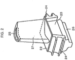
- FIG. 2 is a perspective view showing the entire configuration of a bucket of a gas turbine.
- the bucket of the gas turbine is made of a Ni-based heat resistant alloy (Rene 80).
- the bucket may be used, for example, as a first stage bucket of a gas turbine rotational portion that has three stages of buckets.
- the bucket includes a blade 21, a platform 22, a shank 23, a seal fin 24, and a chip pocket 25, and is attached by way of a dove tail 26 to a disk. Further, length of the blade portion is 100 mm and length of a portion below the platform 22 is 120 mm in the bucket.
- a cooling aperture (not illustrated) for cooling the bucket from the inside is formed from the dove tail 26 via the blade 21 as a passage of cooling mediums, e.g., air or steam.
- TBC was provided at parts of the gas turbine bucket which are exposed to combustion gas, that is, the blade portion 21 and the platform 22. A method of manufacturing the gas turbine bucket is to be described below.
- a bonding layer was formed on a substrate by low pressure plasma spraying of a CoNiCrAlY alloy (Co-32wt% Ni-21wt% Cr-8wt% Al-0.5% Y) powder.
- the layer was further subjected to diffusion heat treatment in vacuum at conditions of 1121°C X 2 h + 843°C X 24 h.
- the thickness of the bonding layer is about 200 ⁇ m.
- a zirconia layer comprising porous ceramics with a thickness of about 0.5 mm and a porosity of about 20% was formed by atmospheric plasma spraying of a yttria-partially stabilized zirconia (ZrO 2 -8wt% Y 2 O 3 ) powder.
- the surface of the zirconia layer was covered by dipping method with a solution containing silica precursor that is a mixture of a marketed ceramic adhesive/filler and water.
- "Aron ceramic C" (trade name) produced by TOAGOSEI CO., LTD. was applied as the marketed agent.
- Durability of the gas turbine bucket of this embodiment was tested by using an actual machine.
- the actual test was performed in a gas turbine that used special A heavy oil as a fuel and in which damage due to molten salt corrosion had been observed.
- a bucket provided with a bonding layer and a thermal barrier layer but not having an environmental barrier layer (bucket provided with existent TBC) was also manufactured in the same method as that for the bucket of this embodiment as described above.
- the bucket for comparison was put to the test simultaneously. After operation for two years, the tested buckets were observed. No damage was confirmed in the TBC of the gas turbine bucket of this embodiment and it remained intact. On the other hand, in the existent bucket of the comparative example, local peeling in the thermal barrier layer was observed.
- the thermal barrier layer was physically ripped off and sampled from the peeled portion in order to analyze the cross section of the thermal barrier layer. As a result of the analysis, S and V were detected. It can therefore be considered that peeling was caused by molten salt corrosion. According to these results, it was confirmed that the gas turbine bucket of this embodiment excels in durability compared with the existent gas turbine bucket. It was also confirmed that the bucket of this embodiment possesses sufficient durability and reliability even for a long time operation under corrosive environment of molten salt employing low grade fuels.
- the bucket of this embodiment is suitable for applying as a first stage bucket which tends to have high temperature.
- the bucket can be used also as a second or subsequent stage bucket.
- FIG. 3 is a perspective view showing the entire configuration of a nozzle in a gas turbine.
- the nozzle of the gas turbine is made of a Co-based heat resistant alloy (FSX414: Co-10wt% Ni-29wt% Cr-7.5wt% W-1wt% Fe-0.4wt% Mn-0.8wt% Si) and used, for example, as a first stage nozzle of the gas turbine that has three stages of nozzles.
- the nozzle has a blade 31 and an end wall portion 32.
- a cooling aperture (not illustrated) is formed from the end face of the end wall 32 through the blade 31 as a passage for cooling mediums, e.g., air or steam in order to cool the blade from inside.
- TBC was provided in the same manner as described for the first embodiment at parts of the gas turbine nozzle exposed to combustion gas, that is, surfaces of the blade 31 and the end wall 32 (combustion gas passage surfaces).
- a bonding layer was formed on the combustion gas passage surfaces of the parts by low pressure plasma spraying of a CoNiCrAlY alloy (Co-32wt% Ni-21wt% Cr-8wt% Al-0.5wt% Y) powder.
- the layer was subjected to diffusion heat treatment in vacuum at conditions of 1121°C X 2h + 843°C X 24h.
- the thickness of the bonding layer is about 200 ⁇ m.
- a zirconia layer comprising porous ceramics having a thickness of about 0.3 mm and a porosity of about 20% was formed by atmospheric plasma spraying of a yttria-partially stabilized zirconia (ZrO 2 -8wt% Y 2 O 3 ) powder.
- the surface of the zirconia layer was covered by dipping method with a solution containing silica precursor that is a mixture of a marketed ceramic adhesive/filler and water.
- "Aron ceramic C" (trade name) produced by TOAGOSEI CO., LTD. was applied as the marketed agent.
- Durability of the gas turbine nozzle of this embodiment was tested by using an actual machine.
- the actual test was performed in a gas turbine that used low sulfur A heavy oil as a fuel and in which damage due to molten salt corrosion had been observed.
- a nozzle provided with a bonding layer and a thermal barrier layer but not having an environmental barrier layer was also manufactured in the same method as that for the nozzle of this embodiment as described above.
- the nozzle for comparison was put to the test simultaneously. After operation for two years, the tested nozzles were observed. No damage was confirmed in the TBC of the gas turbine nozzle of this embodiment and it remained intact.
- the nozzle of this embodiment is suitable for applying as a first stage nozzle which tends to have high temperature.
- the nozzle can be used also as a second or subsequent stage nozzle.
- Fig. 4 is a schematic cross sectional view showing a main portion of a gas turbine used for electric power generation.
- the gas turbine includes, within a turbine casing 48, a rotary shaft (rotor) 49 at the center, and a turbine portion 44 that comprises buckets 46 disposed at the periphery of the rotary shaft 49, nozzles 45 supported at the side of the casing 48, and a turbine shroud 47.
- the gas turbine also has a compressor 50 coupled to the turbine 44 and a combustor 40.
- the compressor 50 intakes atmospheric air for use as a compressed air for combustion and cooling.
- the combustor 40 has a combustor nozzle 41 that mixes the compressed air supplied from the compressor 50 with a supplied fuel (not illustrated) and injects the mixture.
- the gas mixture is burnt in a combustor liner 42 whereby generating high temperature and high pressure combustion gas.
- the combustion gas is supplied to the turbine 44 via a transition piece (tail cylinder) 43 to rotate the rotor 49 at a high speed.
- a portion of the compressed air exhausted from the compressor 50 is used as an internal cooling air for the liner 42 and the transition piece 43 of the combustor 40, and the nozzles 45 and the buckets 46 of the turbine.
- the high temperature and high pressure combustion gas generated in the combustor 40 flows through the transition piece 43 and is rectified by the turbine nozzles 45, and then injected to the buckets 46 to rotationally drive the turbine 44.
- electric power is normally generated by using a generator coupled to the end of the rotary shaft 49.
- This embodiment is such that applies both the described bucket 46 and nozzle 45 in the first and second embodiments as the first stage bucket/nozzles, positioned at a high temperature side in the rotational portion of a gas turbine.
- other parts were also provided with a ceramic coating layer that has an environmental barrier layer by a method basically according to that described for the second embodiment: the parts are, inner circumferential surface of the combustor liner 42 and the transition piece 43 which serves as a combustion gas channel, and the surface of the combustion gas channel of the turbine shroud 47 at the first stage.
- a bonding layer was formed on the combustion gas passage surfaces of the parts by atmospheric plasma spraying of a CoNiCrAlY alloy (Co-32wt% Ni-21wt% Cr-8wt% A1-0.5wt% Y) powder.
- the thickness of the bonding layer is about 200 ⁇ m.
- a zirconia layer comprising porous ceramics with a thickness of about 0.3 mm and a porosity of about 20% was formed by atmospheric plasma spraying of a yttria-partially stabilized zirconia (ZrO 2 -8wt% Y 2 O 3 ) powder.
- the surface of the zirconia layer was covered by dipping method with a solution that is a mixture of a marketed ceramic adhesive/filler and water containing silica precursor.
- "Aron ceramic C” (trade name) produced by TOAGOSEI CO., LTD. was applied as the marketed agent. Water was added in order to condition the viscosity of the solution: in this case the viscosity was conditioned to about 3 Pa • sec at a room temperature.
- the parts were naturally dried at a room temperature for 24 hours. The parts were then heated in an electric furnace at conditions of 90°C X 1h and 150°C X 1h.
- an environmental barrier layer mainly composed of silica was formed on the surface of the porous zirconia layer.
- the ceramic coating layer including the environmental barrier layer of the present invention is applied to the first stage nozzle, the first stage bucket, and the first stage shroud in the turbine 44 configured with three stages.
- the present invention may also be provided to the subsequent second stage and third stage.
- the present invention may also be applied to all or selected stages of turbines having other numbers of stages, for example, two or four stages.
- the gas turbine of this embodiment having the constitution as above was operated by using low sulfur A heavy oil as the fuel. After operation for two years, each of the parts was observed. Damage due to molten salt corrosion was scarcely observed in the TBC of this embodiment for each part of the gas turbine and they remained intact. On the other hand, in the gas turbine using the existent TBC not having the environmental barrier layer of the invention, local peeling due to molten salt corrosion was confirmed in the heat barrier layer of the TBC in a number of components after operation for one year. Thus, repair or replacement of those parts were necessary. The thermal barrier layer was physically ripped off and sampled from the peeled portion of TBC in order to analyze the cross section of the thermal barrier layer. As a result, S and V were detected.
- the result described above indicates the fact that the great corrosion resistance of the high temperature parts allows the gas turbine of this embodiment to operate with high reliability while employing an inexpensive low grade fuel.
- the gas turbine excels in economical efficiency and operation stability and is suitable for power generation plants. It also has sufficient durability and reliability for long time operation under corrosive environment of molten salt employing a low grade fuel. Further, even when the turbine uses low grade fuels, e.g. high sulfur A heavy oils or B, C heavy oils, containing more corrosive ingredients than the low sulfur A heavy oil used in this embodiment, the high temperature parts can be expected to show high durability.
Landscapes
- Chemical & Material Sciences (AREA)
- Engineering & Computer Science (AREA)
- Materials Engineering (AREA)
- Mechanical Engineering (AREA)
- Inorganic Chemistry (AREA)
- Chemical Kinetics & Catalysis (AREA)
- Metallurgy (AREA)
- Organic Chemistry (AREA)
- General Engineering & Computer Science (AREA)
- Ceramic Engineering (AREA)
- Turbine Rotor Nozzle Sealing (AREA)
- Other Surface Treatments For Metallic Materials (AREA)
Claims (11)
- Composant de turbine à gaz pour une utilisation dans un environnement corrosif de sel fondu employant des combustibles de qualité inférieure, le composant de turbine à gaz comprenant un substrat (10) constitué d'un alliage contenant Ni, Co, ou Fe, une couche de liaison (11) constituée d'un alliage disposée sur le substrat (10), et
un revêtement (12, 13, 14) de barrière thermique disposé sur la couche de liaison (11) ;
dans lequel le revêtement de barrière thermique inclut :une couche (12) de barrière thermique de céramique poreuse ;une couche (13) de barrière environnementale, l'épaisseur de la couche (13) de barrière environnementale étant de 0,05 à 0,1 mm et la porosité de la couche (13) de barrière environnementale étant 5% ou moins, ladite couche (13) de barrière environnementale contenant 90% ou plus de silice et pas d'alumine ajoutée ; etune couche (14) d'imprégnation ayant un matériau contenant 90% ou plus de silice et pas d'alumine ajoutée dans les pores de la céramique poreuse. - Composant de turbine à gaz selon la revendication 1, dans lequel la couche (12) de barrière thermique est constitué d'oxyde de zirconium.
- Composant de turbine à gaz selon la revendication 1 ou 2, dans lequel l'épaisseur de la couche (12) de barrière thermique est de 0,1 à 1 mm.
- Composant de turbine à gaz selon l'une quelconque des revendications 1 à 3, dans lequel la porosité de la couche (12) de barrière thermique est dans une plage de 10 à 30%.
- Composant de turbine à gaz selon l'une quelconque des revendications 1 à 4, dans lequel l'épaisseur de la couche (14) d'imprégnation est de 0,01 à 0,1 mm.
- Composant de turbine à gaz selon l'une quelconque des revendications 1 à 5, dans lequel la couche (13) de barrière environnementale est une couche formée en utilisant une solution contenant un précurseur de silice.
- Composant de turbine à gaz selon l'une quelconque des revendications 1 à 6, dans lequel la couche de liaison (11) est d'un alliage MCrAlY ou d'un alliage MCrAl, dans lequel M représente au moins un parmi Fe, Ni, et Co, et la céramique poreuse est d'oxyde de zirconium partiellement stabilisé.
- Composant de turbine à gaz selon l'une des revendications précédentes, dans lequel le composant de turbine à gaz est formé comme une chambre de combustion de turbine à gaz.
- Composant de turbine à gaz selon l'une des revendications précédentes, dans lequel le composant de turbine à gaz est formé comme un carénage de turbine à gaz.
- Composant de turbine à gaz selon l'une des revendications 1 à 7, dans lequel le composant de turbine à gaz est une aube/buse de turbine à gaz.
- Turbine à gaz comprenant un quelconque parmi
l'aube/ la buse selon la revendication 10,
la chambre de combustion selon la revendication 8, et
le carénage selon la revendication 9.
Applications Claiming Priority (1)
| Application Number | Priority Date | Filing Date | Title |
|---|---|---|---|
| JP2010291548A JP5561733B2 (ja) | 2010-12-28 | 2010-12-28 | 遮熱コーティングを有するガスタービン用部品と、それを用いたガスタービン |
Publications (3)
| Publication Number | Publication Date |
|---|---|
| EP2471974A1 EP2471974A1 (fr) | 2012-07-04 |
| EP2471974B1 EP2471974B1 (fr) | 2016-03-16 |
| EP2471974B2 true EP2471974B2 (fr) | 2019-02-27 |
Family
ID=45464291
Family Applications (1)
| Application Number | Title | Priority Date | Filing Date |
|---|---|---|---|
| EP11195047.3A Active EP2471974B2 (fr) | 2010-12-28 | 2011-12-21 | Composant de turbine à gaz doté d'un revêtement formant barrière thermique et turbine à gaz utilisant le composant |
Country Status (3)
| Country | Link |
|---|---|
| US (1) | US20120159952A1 (fr) |
| EP (1) | EP2471974B2 (fr) |
| JP (1) | JP5561733B2 (fr) |
Families Citing this family (15)
| Publication number | Priority date | Publication date | Assignee | Title |
|---|---|---|---|---|
| US9574282B2 (en) * | 2012-08-13 | 2017-02-21 | United Technologies Corporation | Abrasive thermal coating |
| EP2954167B1 (fr) * | 2013-02-10 | 2020-05-06 | United Technologies Corporation | Section de soufflante pour moteur à turbine à gaz avec un film amovible et procédé de protection des surfaces dans une section de soufflante |
| EP2865781A1 (fr) * | 2013-10-22 | 2015-04-29 | Siemens Aktiengesellschaft | Couche céramique à deux couches dotée de microstructures différentes |
| WO2017046942A1 (fr) * | 2015-09-18 | 2017-03-23 | 株式会社 東芝 | Revêtement barrière thermique et système de production de poudre |
| JP6514772B2 (ja) * | 2015-10-23 | 2019-05-15 | 日本特殊陶業株式会社 | 電気化学反応セルスタック |
| US20170122560A1 (en) * | 2015-10-28 | 2017-05-04 | General Electric Company | Gas turbine component with improved thermal barrier coating system |
| US10145000B2 (en) * | 2016-05-27 | 2018-12-04 | General Electric Company | Thermally dissipative article and method of forming a thermally dissipative article |
| FR3053076B1 (fr) * | 2016-06-24 | 2020-03-27 | Snecma | Piece de turbomachine revetue d'une barriere thermique et d'un revetement de protection contre les cmas et procede pour l'obtenir |
| CN106399912A (zh) * | 2016-11-18 | 2017-02-15 | 无锡明盛纺织机械有限公司 | 一种循环流化床锅炉耐高温抗磨蚀梯度涂层的制备方法 |
| JPWO2018181559A1 (ja) * | 2017-03-28 | 2020-02-06 | 三菱重工業株式会社 | 遮熱コーティング皮膜およびタービン部材 |
| RU2681675C2 (ru) * | 2017-07-25 | 2019-03-12 | Акционерное общество "Высокотехнологический научно-исследовательский институт неорганических материалов имени академика А.А. Бочвара" | Портативное устройство для газодинамического напыления покрытий |
| RU2681858C2 (ru) * | 2017-07-25 | 2019-03-13 | Акционерное общество "Высокотехнологический научно-исследовательский институт неорганических материалов имени академика А.А. Бочвара" | Портативное устройство для газодинамического напыления покрытий |
| US20200369576A1 (en) * | 2017-08-14 | 2020-11-26 | Nissan Motor Co., Ltd. | Heat Shield Component and Manufacturing Method Thereof |
| JP7169077B2 (ja) | 2018-03-26 | 2022-11-10 | 三菱重工業株式会社 | 遮熱コーティング、タービン部材、ガスタービン及び遮熱コーティングの製造方法 |
| CN112941451B (zh) * | 2021-01-25 | 2022-08-05 | 武汉理工大学 | 一种提高热障涂层在自然环境下稳定性的方法 |
Citations (4)
| Publication number | Priority date | Publication date | Assignee | Title |
|---|---|---|---|---|
| US5773141A (en) † | 1995-04-06 | 1998-06-30 | General Electric Company | Protected thermal barrier coating composite |
| EP0852223A1 (fr) † | 1996-12-04 | 1998-07-08 | European Atomic Energy Community (Euratom) | Procédé pour boucher des revêtements poreux, en particulier des barrières thermiques |
| US20060068189A1 (en) † | 2004-09-27 | 2006-03-30 | Derek Raybould | Method of forming stabilized plasma-sprayed thermal barrier coatings |
| EP2053141A1 (fr) † | 2007-10-24 | 2009-04-29 | General Electric Company | Revêtements protecteurs à base d'alumine pour revêtements de barrière thermique |
Family Cites Families (10)
| Publication number | Priority date | Publication date | Assignee | Title |
|---|---|---|---|---|
| JPS62211387A (ja) | 1986-03-12 | 1987-09-17 | Hitachi Ltd | セラミツク被覆耐熱部材の製造方法 |
| JP2845144B2 (ja) * | 1994-02-10 | 1999-01-13 | 住友金属工業株式会社 | 溶融金属めっき浴浸漬部材とその製造方法 |
| JP3219594B2 (ja) * | 1994-04-27 | 2001-10-15 | 三菱重工業株式会社 | 高温酸化防止用遮熱コーティング方法 |
| US5871820A (en) | 1995-04-06 | 1999-02-16 | General Electric Company | Protection of thermal barrier coating with an impermeable barrier coating |
| JPH0978258A (ja) * | 1995-09-20 | 1997-03-25 | Toshiba Corp | 遮熱コーティングを有する高温部材およびその製造方法 |
| US7368164B2 (en) | 2004-06-18 | 2008-05-06 | General Electric Company | Smooth outer coating for combustor components and coating method therefor |
| US20070116883A1 (en) * | 2005-11-22 | 2007-05-24 | General Electric Company | Process for forming thermal barrier coating resistant to infiltration |
| WO2007112783A1 (fr) * | 2006-04-06 | 2007-10-11 | Siemens Aktiengesellschaft | Revetement stratifie formant une barriere thermique a porosite elevee et composant |
| EP2128299B1 (fr) * | 2008-05-29 | 2016-12-28 | General Electric Technology GmbH | Structure de préambule de synchronisation pour système OFDM |
| JP5075880B2 (ja) * | 2009-06-30 | 2012-11-21 | 株式会社日立製作所 | 耐熱部材およびガスタービン用高温部品 |
-
2010
- 2010-12-28 JP JP2010291548A patent/JP5561733B2/ja active Active
-
2011
- 2011-12-21 EP EP11195047.3A patent/EP2471974B2/fr active Active
- 2011-12-21 US US13/332,605 patent/US20120159952A1/en not_active Abandoned
Patent Citations (4)
| Publication number | Priority date | Publication date | Assignee | Title |
|---|---|---|---|---|
| US5773141A (en) † | 1995-04-06 | 1998-06-30 | General Electric Company | Protected thermal barrier coating composite |
| EP0852223A1 (fr) † | 1996-12-04 | 1998-07-08 | European Atomic Energy Community (Euratom) | Procédé pour boucher des revêtements poreux, en particulier des barrières thermiques |
| US20060068189A1 (en) † | 2004-09-27 | 2006-03-30 | Derek Raybould | Method of forming stabilized plasma-sprayed thermal barrier coatings |
| EP2053141A1 (fr) † | 2007-10-24 | 2009-04-29 | General Electric Company | Revêtements protecteurs à base d'alumine pour revêtements de barrière thermique |
Also Published As
| Publication number | Publication date |
|---|---|
| US20120159952A1 (en) | 2012-06-28 |
| JP5561733B2 (ja) | 2014-07-30 |
| EP2471974B1 (fr) | 2016-03-16 |
| JP2012137073A (ja) | 2012-07-19 |
| EP2471974A1 (fr) | 2012-07-04 |
Similar Documents
| Publication | Publication Date | Title |
|---|---|---|
| EP2471974B2 (fr) | Composant de turbine à gaz doté d'un revêtement formant barrière thermique et turbine à gaz utilisant le composant | |
| JP5075880B2 (ja) | 耐熱部材およびガスタービン用高温部品 | |
| US7833586B2 (en) | Alumina-based protective coatings for thermal barrier coatings | |
| US5683825A (en) | Thermal barrier coating resistant to erosion and impact by particulate matter | |
| EP2503027B1 (fr) | Revêtements résistant à la corrosion à chaud et composants ainsi protégés | |
| EP1218564B1 (fr) | Formation in situ de revetements barriere par pulverisation d'air plasma multiphases pour composants de turbine | |
| US6365281B1 (en) | Thermal barrier coatings for turbine components | |
| EP1939317A2 (fr) | Revêtement de barrière thermique | |
| US6548190B2 (en) | Low thermal conductivity thermal barrier coating system and method therefor | |
| US20160333455A1 (en) | Thermal Barrier Coating with Lower Thermal Conductivity | |
| JP2007015913A (ja) | Ebcのためのシリコン含有基材の結合コートおよび同物を製造するプロセス | |
| JP2007182631A (ja) | Cmas劣化耐性の向上したランタニド系列酸化物を含む積層遮熱コーティング | |
| JP2011167994A (ja) | 遮熱コーティングを有する耐熱部材と、それを用いたガスタービン用部品 | |
| US20150247245A1 (en) | Protective coating systems for gas turbine engine applications and methods for fabricating the same | |
| US8722202B2 (en) | Method and system for enhancing heat transfer of turbine engine components | |
| US11473432B2 (en) | Anti-CMAS coating with enhanced efficiency | |
| US20170145836A1 (en) | Articles having damage-tolerant thermal barrier coating | |
| CN112204163B (zh) | 耐cmas、耐高应变和低热导率热障涂层和热喷涂法 | |
| US11566531B2 (en) | CMAS-resistant abradable coatings | |
| JP5702749B2 (ja) | ガスタービン翼、燃焼器、シュラウド及びこれらを用いたガスタービン | |
| JP2018184662A (ja) | 高温用の物品 | |
| Stolle | Conventional and advanced coatings for turbine airfoils | |
| Lehmann et al. | Thermally sprayed thermal barrier coating (TBC) systems: a survey of recent patents |
Legal Events
| Date | Code | Title | Description |
|---|---|---|---|
| 17P | Request for examination filed |
Effective date: 20120313 |
|
| AK | Designated contracting states |
Kind code of ref document: A1 Designated state(s): AL AT BE BG CH CY CZ DE DK EE ES FI FR GB GR HR HU IE IS IT LI LT LU LV MC MK MT NL NO PL PT RO RS SE SI SK SM TR |
|
| AX | Request for extension of the european patent |
Extension state: BA ME |
|
| PUAI | Public reference made under article 153(3) epc to a published international application that has entered the european phase |
Free format text: ORIGINAL CODE: 0009012 |
|
| RAP1 | Party data changed (applicant data changed or rights of an application transferred) |
Owner name: MITSUBISHI HITACHI POWER SYSTEMS, LTD. |
|
| RAP1 | Party data changed (applicant data changed or rights of an application transferred) |
Owner name: MITSUBISHI HITACHI POWER SYSTEMS, LTD. |
|
| GRAP | Despatch of communication of intention to grant a patent |
Free format text: ORIGINAL CODE: EPIDOSNIGR1 |
|
| INTG | Intention to grant announced |
Effective date: 20150717 |
|
| GRAS | Grant fee paid |
Free format text: ORIGINAL CODE: EPIDOSNIGR3 |
|
| GRAA | (expected) grant |
Free format text: ORIGINAL CODE: 0009210 |
|
| AK | Designated contracting states |
Kind code of ref document: B1 Designated state(s): AL AT BE BG CH CY CZ DE DK EE ES FI FR GB GR HR HU IE IS IT LI LT LU LV MC MK MT NL NO PL PT RO RS SE SI SK SM TR |
|
| REG | Reference to a national code |
Ref country code: GB Ref legal event code: FG4D |
|
| REG | Reference to a national code |
Ref country code: CH Ref legal event code: EP |
|
| REG | Reference to a national code |
Ref country code: IE Ref legal event code: FG4D |
|
| REG | Reference to a national code |
Ref country code: AT Ref legal event code: REF Ref document number: 781330 Country of ref document: AT Kind code of ref document: T Effective date: 20160415 |
|
| REG | Reference to a national code |
Ref country code: DE Ref legal event code: R096 Ref document number: 602011024010 Country of ref document: DE |
|
| REG | Reference to a national code |
Ref country code: NL Ref legal event code: MP Effective date: 20160316 |
|
| REG | Reference to a national code |
Ref country code: LT Ref legal event code: MG4D |
|
| PG25 | Lapsed in a contracting state [announced via postgrant information from national office to epo] |
Ref country code: NO Free format text: LAPSE BECAUSE OF FAILURE TO SUBMIT A TRANSLATION OF THE DESCRIPTION OR TO PAY THE FEE WITHIN THE PRESCRIBED TIME-LIMIT Effective date: 20160616 Ref country code: HR Free format text: LAPSE BECAUSE OF FAILURE TO SUBMIT A TRANSLATION OF THE DESCRIPTION OR TO PAY THE FEE WITHIN THE PRESCRIBED TIME-LIMIT Effective date: 20160316 Ref country code: GR Free format text: LAPSE BECAUSE OF FAILURE TO SUBMIT A TRANSLATION OF THE DESCRIPTION OR TO PAY THE FEE WITHIN THE PRESCRIBED TIME-LIMIT Effective date: 20160617 Ref country code: FI Free format text: LAPSE BECAUSE OF FAILURE TO SUBMIT A TRANSLATION OF THE DESCRIPTION OR TO PAY THE FEE WITHIN THE PRESCRIBED TIME-LIMIT Effective date: 20160316 |
|
| REG | Reference to a national code |
Ref country code: AT Ref legal event code: MK05 Ref document number: 781330 Country of ref document: AT Kind code of ref document: T Effective date: 20160316 |
|
| PG25 | Lapsed in a contracting state [announced via postgrant information from national office to epo] |
Ref country code: NL Free format text: LAPSE BECAUSE OF FAILURE TO SUBMIT A TRANSLATION OF THE DESCRIPTION OR TO PAY THE FEE WITHIN THE PRESCRIBED TIME-LIMIT Effective date: 20160316 Ref country code: LT Free format text: LAPSE BECAUSE OF FAILURE TO SUBMIT A TRANSLATION OF THE DESCRIPTION OR TO PAY THE FEE WITHIN THE PRESCRIBED TIME-LIMIT Effective date: 20160316 Ref country code: LV Free format text: LAPSE BECAUSE OF FAILURE TO SUBMIT A TRANSLATION OF THE DESCRIPTION OR TO PAY THE FEE WITHIN THE PRESCRIBED TIME-LIMIT Effective date: 20160316 Ref country code: RS Free format text: LAPSE BECAUSE OF FAILURE TO SUBMIT A TRANSLATION OF THE DESCRIPTION OR TO PAY THE FEE WITHIN THE PRESCRIBED TIME-LIMIT Effective date: 20160316 Ref country code: SE Free format text: LAPSE BECAUSE OF FAILURE TO SUBMIT A TRANSLATION OF THE DESCRIPTION OR TO PAY THE FEE WITHIN THE PRESCRIBED TIME-LIMIT Effective date: 20160316 |
|
| REG | Reference to a national code |
Ref country code: DE Ref legal event code: R026 Ref document number: 602011024010 Country of ref document: DE |
|
| PLBI | Opposition filed |
Free format text: ORIGINAL CODE: 0009260 |
|
| PG25 | Lapsed in a contracting state [announced via postgrant information from national office to epo] |
Ref country code: IS Free format text: LAPSE BECAUSE OF FAILURE TO SUBMIT A TRANSLATION OF THE DESCRIPTION OR TO PAY THE FEE WITHIN THE PRESCRIBED TIME-LIMIT Effective date: 20160716 Ref country code: PL Free format text: LAPSE BECAUSE OF FAILURE TO SUBMIT A TRANSLATION OF THE DESCRIPTION OR TO PAY THE FEE WITHIN THE PRESCRIBED TIME-LIMIT Effective date: 20160316 Ref country code: EE Free format text: LAPSE BECAUSE OF FAILURE TO SUBMIT A TRANSLATION OF THE DESCRIPTION OR TO PAY THE FEE WITHIN THE PRESCRIBED TIME-LIMIT Effective date: 20160316 |
|
| REG | Reference to a national code |
Ref country code: FR Ref legal event code: PLFP Year of fee payment: 6 |
|
| 26 | Opposition filed |
Opponent name: SIEMENS AKTIENGESELLSCHAFT Effective date: 20161018 |
|
| PG25 | Lapsed in a contracting state [announced via postgrant information from national office to epo] |
Ref country code: SK Free format text: LAPSE BECAUSE OF FAILURE TO SUBMIT A TRANSLATION OF THE DESCRIPTION OR TO PAY THE FEE WITHIN THE PRESCRIBED TIME-LIMIT Effective date: 20160316 Ref country code: CZ Free format text: LAPSE BECAUSE OF FAILURE TO SUBMIT A TRANSLATION OF THE DESCRIPTION OR TO PAY THE FEE WITHIN THE PRESCRIBED TIME-LIMIT Effective date: 20160316 Ref country code: PT Free format text: LAPSE BECAUSE OF FAILURE TO SUBMIT A TRANSLATION OF THE DESCRIPTION OR TO PAY THE FEE WITHIN THE PRESCRIBED TIME-LIMIT Effective date: 20160718 Ref country code: ES Free format text: LAPSE BECAUSE OF FAILURE TO SUBMIT A TRANSLATION OF THE DESCRIPTION OR TO PAY THE FEE WITHIN THE PRESCRIBED TIME-LIMIT Effective date: 20160316 Ref country code: AT Free format text: LAPSE BECAUSE OF FAILURE TO SUBMIT A TRANSLATION OF THE DESCRIPTION OR TO PAY THE FEE WITHIN THE PRESCRIBED TIME-LIMIT Effective date: 20160316 Ref country code: SM Free format text: LAPSE BECAUSE OF FAILURE TO SUBMIT A TRANSLATION OF THE DESCRIPTION OR TO PAY THE FEE WITHIN THE PRESCRIBED TIME-LIMIT Effective date: 20160316 Ref country code: RO Free format text: LAPSE BECAUSE OF FAILURE TO SUBMIT A TRANSLATION OF THE DESCRIPTION OR TO PAY THE FEE WITHIN THE PRESCRIBED TIME-LIMIT Effective date: 20160316 |
|
| PG25 | Lapsed in a contracting state [announced via postgrant information from national office to epo] |
Ref country code: BE Free format text: LAPSE BECAUSE OF FAILURE TO SUBMIT A TRANSLATION OF THE DESCRIPTION OR TO PAY THE FEE WITHIN THE PRESCRIBED TIME-LIMIT Effective date: 20160316 Ref country code: IT Free format text: LAPSE BECAUSE OF FAILURE TO SUBMIT A TRANSLATION OF THE DESCRIPTION OR TO PAY THE FEE WITHIN THE PRESCRIBED TIME-LIMIT Effective date: 20160316 |
|
| PG25 | Lapsed in a contracting state [announced via postgrant information from national office to epo] |
Ref country code: DK Free format text: LAPSE BECAUSE OF FAILURE TO SUBMIT A TRANSLATION OF THE DESCRIPTION OR TO PAY THE FEE WITHIN THE PRESCRIBED TIME-LIMIT Effective date: 20160316 |
|
| PLAX | Notice of opposition and request to file observation + time limit sent |
Free format text: ORIGINAL CODE: EPIDOSNOBS2 |
|
| PG25 | Lapsed in a contracting state [announced via postgrant information from national office to epo] |
Ref country code: BG Free format text: LAPSE BECAUSE OF FAILURE TO SUBMIT A TRANSLATION OF THE DESCRIPTION OR TO PAY THE FEE WITHIN THE PRESCRIBED TIME-LIMIT Effective date: 20160616 |
|
| PG25 | Lapsed in a contracting state [announced via postgrant information from national office to epo] |
Ref country code: SI Free format text: LAPSE BECAUSE OF FAILURE TO SUBMIT A TRANSLATION OF THE DESCRIPTION OR TO PAY THE FEE WITHIN THE PRESCRIBED TIME-LIMIT Effective date: 20160316 |
|
| PLBB | Reply of patent proprietor to notice(s) of opposition received |
Free format text: ORIGINAL CODE: EPIDOSNOBS3 |
|
| REG | Reference to a national code |
Ref country code: CH Ref legal event code: PL |
|
| PG25 | Lapsed in a contracting state [announced via postgrant information from national office to epo] |
Ref country code: MC Free format text: LAPSE BECAUSE OF FAILURE TO SUBMIT A TRANSLATION OF THE DESCRIPTION OR TO PAY THE FEE WITHIN THE PRESCRIBED TIME-LIMIT Effective date: 20160316 |
|
| REG | Reference to a national code |
Ref country code: IE Ref legal event code: MM4A |
|
| PG25 | Lapsed in a contracting state [announced via postgrant information from national office to epo] |
Ref country code: LU Free format text: LAPSE BECAUSE OF NON-PAYMENT OF DUE FEES Effective date: 20161221 Ref country code: CH Free format text: LAPSE BECAUSE OF NON-PAYMENT OF DUE FEES Effective date: 20161231 Ref country code: LI Free format text: LAPSE BECAUSE OF NON-PAYMENT OF DUE FEES Effective date: 20161231 |
|
| PLAB | Opposition data, opponent's data or that of the opponent's representative modified |
Free format text: ORIGINAL CODE: 0009299OPPO |
|
| REG | Reference to a national code |
Ref country code: FR Ref legal event code: PLFP Year of fee payment: 7 |
|
| PG25 | Lapsed in a contracting state [announced via postgrant information from national office to epo] |
Ref country code: IE Free format text: LAPSE BECAUSE OF NON-PAYMENT OF DUE FEES Effective date: 20161221 |
|
| R26 | Opposition filed (corrected) |
Opponent name: SIEMENS AKTIENGESELLSCHAFT Effective date: 20161018 |
|
| PG25 | Lapsed in a contracting state [announced via postgrant information from national office to epo] |
Ref country code: HU Free format text: LAPSE BECAUSE OF FAILURE TO SUBMIT A TRANSLATION OF THE DESCRIPTION OR TO PAY THE FEE WITHIN THE PRESCRIBED TIME-LIMIT; INVALID AB INITIO Effective date: 20111221 Ref country code: CY Free format text: LAPSE BECAUSE OF FAILURE TO SUBMIT A TRANSLATION OF THE DESCRIPTION OR TO PAY THE FEE WITHIN THE PRESCRIBED TIME-LIMIT Effective date: 20160316 |
|
| PG25 | Lapsed in a contracting state [announced via postgrant information from national office to epo] |
Ref country code: TR Free format text: LAPSE BECAUSE OF FAILURE TO SUBMIT A TRANSLATION OF THE DESCRIPTION OR TO PAY THE FEE WITHIN THE PRESCRIBED TIME-LIMIT Effective date: 20160316 Ref country code: MK Free format text: LAPSE BECAUSE OF FAILURE TO SUBMIT A TRANSLATION OF THE DESCRIPTION OR TO PAY THE FEE WITHIN THE PRESCRIBED TIME-LIMIT Effective date: 20160316 |
|
| PG25 | Lapsed in a contracting state [announced via postgrant information from national office to epo] |
Ref country code: MT Free format text: LAPSE BECAUSE OF NON-PAYMENT OF DUE FEES Effective date: 20161221 |
|
| PG25 | Lapsed in a contracting state [announced via postgrant information from national office to epo] |
Ref country code: AL Free format text: LAPSE BECAUSE OF FAILURE TO SUBMIT A TRANSLATION OF THE DESCRIPTION OR TO PAY THE FEE WITHIN THE PRESCRIBED TIME-LIMIT Effective date: 20160316 |
|
| PUAH | Patent maintained in amended form |
Free format text: ORIGINAL CODE: 0009272 |
|
| STAA | Information on the status of an ep patent application or granted ep patent |
Free format text: STATUS: PATENT MAINTAINED AS AMENDED |
|
| 27A | Patent maintained in amended form |
Effective date: 20190227 |
|
| AK | Designated contracting states |
Kind code of ref document: B2 Designated state(s): AL AT BE BG CH CY CZ DE DK EE ES FI FR GB GR HR HU IE IS IT LI LT LU LV MC MK MT NL NO PL PT RO RS SE SI SK SM TR |
|
| REG | Reference to a national code |
Ref country code: DE Ref legal event code: R102 Ref document number: 602011024010 Country of ref document: DE |
|
| REG | Reference to a national code |
Ref country code: DE Ref legal event code: R082 Ref document number: 602011024010 Country of ref document: DE Representative=s name: BEETZ & PARTNER MBB PATENTANWAELTE, DE Ref country code: DE Ref legal event code: R081 Ref document number: 602011024010 Country of ref document: DE Owner name: MITSUBISHI POWER, LTD., JP Free format text: FORMER OWNER: MITSUBISHI HITACHI POWER SYSTEMS, LTD., YOKOHAMA-SHI, KANAGAWA, JP |
|
| PGFP | Annual fee paid to national office [announced via postgrant information from national office to epo] |
Ref country code: GB Payment date: 20231102 Year of fee payment: 13 |
|
| PGFP | Annual fee paid to national office [announced via postgrant information from national office to epo] |
Ref country code: FR Payment date: 20231108 Year of fee payment: 13 Ref country code: DE Payment date: 20231031 Year of fee payment: 13 |