EP2470346B1 - Injection molding of part having nonuniform thickness - Google Patents
Injection molding of part having nonuniform thickness Download PDFInfo
- Publication number
- EP2470346B1 EP2470346B1 EP10814217.5A EP10814217A EP2470346B1 EP 2470346 B1 EP2470346 B1 EP 2470346B1 EP 10814217 A EP10814217 A EP 10814217A EP 2470346 B1 EP2470346 B1 EP 2470346B1
- Authority
- EP
- European Patent Office
- Prior art keywords
- mold surface
- mold
- thermoplastic material
- side walls
- injection molding
- Prior art date
- Legal status (The legal status is an assumption and is not a legal conclusion. Google has not performed a legal analysis and makes no representation as to the accuracy of the status listed.)
- Not-in-force
Links
Images

Classifications
-
- B—PERFORMING OPERATIONS; TRANSPORTING
- B29—WORKING OF PLASTICS; WORKING OF SUBSTANCES IN A PLASTIC STATE IN GENERAL
- B29C—SHAPING OR JOINING OF PLASTICS; SHAPING OF MATERIAL IN A PLASTIC STATE, NOT OTHERWISE PROVIDED FOR; AFTER-TREATMENT OF THE SHAPED PRODUCTS, e.g. REPAIRING
- B29C45/00—Injection moulding, i.e. forcing the required volume of moulding material through a nozzle into a closed mould; Apparatus therefor
- B29C45/17—Component parts, details or accessories; Auxiliary operations
- B29C45/26—Moulds
- B29C45/33—Moulds having transversely, e.g. radially, movable mould parts
-
- B—PERFORMING OPERATIONS; TRANSPORTING
- B29—WORKING OF PLASTICS; WORKING OF SUBSTANCES IN A PLASTIC STATE IN GENERAL
- B29D—PRODUCING PARTICULAR ARTICLES FROM PLASTICS OR FROM SUBSTANCES IN A PLASTIC STATE
- B29D11/00—Producing optical elements, e.g. lenses or prisms
- B29D11/00663—Production of light guides
-
- B—PERFORMING OPERATIONS; TRANSPORTING
- B29—WORKING OF PLASTICS; WORKING OF SUBSTANCES IN A PLASTIC STATE IN GENERAL
- B29C—SHAPING OR JOINING OF PLASTICS; SHAPING OF MATERIAL IN A PLASTIC STATE, NOT OTHERWISE PROVIDED FOR; AFTER-TREATMENT OF THE SHAPED PRODUCTS, e.g. REPAIRING
- B29C33/00—Moulds or cores; Details thereof or accessories therefor
- B29C33/20—Opening, closing or clamping
- B29C33/26—Opening, closing or clamping by pivotal movement
-
- B—PERFORMING OPERATIONS; TRANSPORTING
- B29—WORKING OF PLASTICS; WORKING OF SUBSTANCES IN A PLASTIC STATE IN GENERAL
- B29C—SHAPING OR JOINING OF PLASTICS; SHAPING OF MATERIAL IN A PLASTIC STATE, NOT OTHERWISE PROVIDED FOR; AFTER-TREATMENT OF THE SHAPED PRODUCTS, e.g. REPAIRING
- B29C45/00—Injection moulding, i.e. forcing the required volume of moulding material through a nozzle into a closed mould; Apparatus therefor
- B29C45/17—Component parts, details or accessories; Auxiliary operations
- B29C45/46—Means for plasticising or homogenising the moulding material or forcing it into the mould
- B29C45/56—Means for plasticising or homogenising the moulding material or forcing it into the mould using mould parts movable during or after injection, e.g. injection-compression moulding
- B29C45/561—Injection-compression moulding
-
- B—PERFORMING OPERATIONS; TRANSPORTING
- B29—WORKING OF PLASTICS; WORKING OF SUBSTANCES IN A PLASTIC STATE IN GENERAL
- B29C—SHAPING OR JOINING OF PLASTICS; SHAPING OF MATERIAL IN A PLASTIC STATE, NOT OTHERWISE PROVIDED FOR; AFTER-TREATMENT OF THE SHAPED PRODUCTS, e.g. REPAIRING
- B29C45/00—Injection moulding, i.e. forcing the required volume of moulding material through a nozzle into a closed mould; Apparatus therefor
- B29C45/17—Component parts, details or accessories; Auxiliary operations
- B29C45/76—Measuring, controlling or regulating
- B29C45/80—Measuring, controlling or regulating of relative position of mould parts
-
- B—PERFORMING OPERATIONS; TRANSPORTING
- B29—WORKING OF PLASTICS; WORKING OF SUBSTANCES IN A PLASTIC STATE IN GENERAL
- B29C—SHAPING OR JOINING OF PLASTICS; SHAPING OF MATERIAL IN A PLASTIC STATE, NOT OTHERWISE PROVIDED FOR; AFTER-TREATMENT OF THE SHAPED PRODUCTS, e.g. REPAIRING
- B29C45/00—Injection moulding, i.e. forcing the required volume of moulding material through a nozzle into a closed mould; Apparatus therefor
- B29C45/17—Component parts, details or accessories; Auxiliary operations
- B29C45/46—Means for plasticising or homogenising the moulding material or forcing it into the mould
- B29C45/57—Exerting after-pressure on the moulding material
-
- B—PERFORMING OPERATIONS; TRANSPORTING
- B29—WORKING OF PLASTICS; WORKING OF SUBSTANCES IN A PLASTIC STATE IN GENERAL
- B29L—INDEXING SCHEME ASSOCIATED WITH SUBCLASS B29C, RELATING TO PARTICULAR ARTICLES
- B29L2011/00—Optical elements, e.g. lenses, prisms
Definitions
- Injection molding is a manufacturing process that may be used for producing plastic parts. Injection molding generally involves injecting molten plastic into a mold, and then allowing the plastic to cool and solidify. However, many plastics shrink while cooling. Therefore, it may be challenging to manufacture parts of a precise thickness via injection molding. Further, because the magnitude of shrinkage is dependent upon the thickness of the plastic, various portions of a nonuniform plastic part may shrink at different rates, thereby compounding the difficulties in molding precision parts via injection molding.
- one disclosed embodiment provides an injection molding device comprising one or more side walls, a first mold surface intersecting the side walls and being stationary with respect to the side walls, and a second mold surface intersecting the side walls so as to define with the side walls and the first mold surface a cavity configured to receive a quantity of injected molten thermoplastic material.
- the second mold surface is configured to be moveable toward the first mold surface in such a manner that a first end of the second mold surface moves a larger physical travel distance toward the first mold surface than does a second end of the second mold surface when molding the thermoplastic material.
- WO-A-02078930 discloses tilting a mould clamping element in relation to another mould clamping element. Further, both linear and rotational movement of sidewalls of a device is disclosed.
- Injection molding of a part having a nonuniform thickness may be challenging in that materials used for such parts may shrink during solidification, thereby causing non-uniform shrinkage due to the varying thickness of the part.
- Shrinkage during molding of a uniform part may be compensated for by moving one surface of a mold toward another surface in a linear manner as the plastic cools and sets.
- such linear motion may not work, as thinner portions of the part that undergo less shrinkage may cause the mold to lock, and thereby not permitting further motion of the mold as the thicker portion of the part continues to set up. This may cause the final part to have incorrect dimensions, and also may impact reproducibility of the molded part.
- injection molding of a part having a nonuniform thickness as described herein utilizes a mold surface configured to be moved toward another mold surfaced in a nonlinear manner (e.g. by allowing rotation of the mold surface about an axis) when molding the thermoplastic material.
- a mold surface configured to be moved toward another mold surfaced in a nonlinear manner (e.g. by allowing rotation of the mold surface about an axis) when molding the thermoplastic material.
- the mold surface may be both linearly and rotatably movable with respect to another mold surface to allow different motion to occur during different phases of a cooling process. While the disclosed embodiments utilize a rotational mechanism to allow such nonlinear motion to occur, it will be understood that a mold according to the present disclosure may utilize any other suitable mechanism for nonlinear motion.
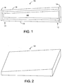
- Fig. 1 shows an exploded schematic view of an embodiment of an example injection molding device 100 that may be used for molding a part having a nonuniform thickness, such as example part 102, depicted schematically as an optical wedge and shown in perspective in Fig. 2 .
- injection molding device 100 may include a plurality of side walls, including side wall 104 and side wall 106, as well as side walls that intersect side walls 104 and 106 to form a rectangular structure.
- Injection molding device 100 further include major top and bottom surfaces (referring to the orientation of Fig. 1 ), which are referred to herein as a first mold surface 108 and a second mold surface 110.
- First mold surface 108 may intersect the side walls such as side wall 104 and side wall 106, and may be stationary with respect to the side walls.
- Second mold surface 110 may also intersect the side walls, such as side wall 104 and side wall 106, so as to define with the side walls and first mold surface 108 surface a cavity.
- Such a cavity may be configured to receive a quantity of injected molten thermoplastic material, which upon solidifying becomes part 102.
- second mold surface 110 may be moveable toward the first mold surface 108 in such a manner that a first end 112 of second mold surface 110 moves a larger physical travel distance toward first mold surface 108 than does a second end 114 of second mold surface 110 when molding the thermoplastic material.
- Such a configuration will be described in more detail as follows with reference to Figs. 3 and 4 .
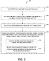
- Fig. 3 shows a flow diagram of an embodiment of a method 300 of injection molding a part having a nonuniform thickness.
- method 300 may optionally include, at 302, heating a first mold surface of an injection mold such that plastic injected into the mold does not instantly start to harden on the first surface.
- some embodiments of method 300 may optionally include, at 304, heating a second mold surface of the injection mold, where the second mold surface is linearly and rotatably moveable toward the first mold surface.
- Fig. 4 which shows a schematic depiction of a time sequence for an embodiment of injection molding of a part having a nonuniform thickness, shows examples of first and second mold surfaces respectively at 402 and 404.
- a heater is shown for surface 404 schematically at 405. The heater is not shown for surface 402, or other mold surfaces, for the purpose of clarity. It will be understood that other mold surfaces than surfaces 402 and 404, such as the side walls 406 and 408, also may be heated prior to injection of plastic into the mold.
- method 300 includes injecting a molten thermoplastic material into the mold cavity.
- the mold cavity may be defined by a first mold surface, a second mold surface, and a plurality of sides extending between the first mold surface and the second mold surface, where the second mold surface being moveable toward the first mold surface.
- the thermoplastic material may be injected into the cavity in any suitable manner.
- the molten thermoplastic material may be injected through an opening in the second mold surface, while in other embodiments, the molten thermoplastic material may be injected into the mold at any other suitable location.
- mold cavity 410 has been filled with thermoplastic material 412.
- Mold cavity 410 may be initially defined such that a thin end and a thick end of the molten plastic are thicker than desired for the component to accommodate the greater volume for the molten thermoplastic material relative to a hardened thermoplastic material. Then, as is described in more detail below, during cooling of the thermoplastic material, the second mold surface 404 is moved toward the first mold surface 402 to keep the mold surfaces in contact with the thermoplastic material as the material cools, thereby achieving desired dimensional and surface properties in the final molded part.
- the thermoplastic material may be any suitable material.
- the thermoplastic material may be transparent, and in more specific embodiments, may comprise a material such as poly(methyl methacrylate) (PMMA), polycarbonate and/or polycyclic olefin. It will be understood that these materials are presented for the purpose of example, and that any other suitable material may be used in any other suitable molding process.
- one or more of the side walls, the first mold surface and the second mold surface may be heated prior to and/or while injecting the molten thermoplastic material. Such heating of the side walls and cavity surfaces may prevent the thermoplastic material from thermal shock upon injection.
- method 300 includes, during cooling of the thermoplastic material in the mold cavity, moving the second surface toward the first mold surface such that a first end of the second mold surface moves a larger physical travel distance than does a second end of the second mold surface, thereby forming the part having the nonuniform thickness.
- 308 of method 300 may include linearly moving and rotatably moving (i.e. rotating) the second mold surface toward the first mold surface, either simultaneously or during different phases of a molding process.
- linearly moving the second mold surface toward the first mold surface refers to movement of the second mold surface such that a first end of the second mold surface moves a same physical travel distance as does a second end of the second mold surface.
- Fig. 4 illustrates at 414 linear compression being applied to the second mold surface 404 in a direction toward first mold surface 402, such that a first end 416 of the second mold surface 404 and a second end 418 of the second mold surface 404 move approximately a same physical travel distance toward first mold surface 402.
- injection molding device 400 may include a physical stop to limit an amount of physical travel distance of the second mold surface so that second mold surface 404 may be linearly moved toward first mold surface 402 for a portion of its travel path toward first mold surface 402. While the second mold surface 404 that is movable toward the stationary first mold surface is depicted as comprising an entire bottom side of the mold cavity (referring to the orientation of the mold shown in Fig. 4 ), it will be understood that in some embodiments, the second mold surface may comprise only a portion of a side of the mold cavity.
- Second mold surface 404 may be rotated in any suitable manner.
- injection molding device 400 may include a hinge 420 about which second mold surface 404 may rotate.
- a hinge 420 may be coupled to one or more sidewalls such as side wall 408, and may allow at least a portion of the second mold surface 404 to rotate about an axis at the second end 418 of second mold surface 404.
- hinge as used herein comprises hinges, pivots, and other such rotational couplings of two parts.
- linear movement of second mold surface 404 toward first mold surface 402 as illustrated at t 1 may be used to achieve a desired thickness at a thin end of the part.
- second mold surface 404 may then be rotatably moved toward first mold surface 402 to achieve a desired thickness at the thick end of the part.
- the final part has the desired nonuniform thickness.
- injection molding as described herein allows for precisely controlling of the various thickness of a part by linearly and rotatably moving the second mold surface toward the first mold surface in a controlled manner so that the mold provides compressive force to the entire part during its entire cooling cycle.
- An injection molding machine may be configured to move second mold surface 404 toward first mold surface 402 in any suitable manner.
- a molding machine to which the injection molding device 400 is coupled may include a compression core configured to move the second mold surface toward the first mold surface.
- a compression core may include a cam mechanism, hydraulic cylinders, gear rack and pinion, or any other suitable mechanism for moving the second mold surface.
- injection molding as described herein may be used to create an optical wedge that may be used as a light-guide in a large display, or may be used in a smaller form factor suitable for an interactive keyboard, mouse or webcam, or in any other suitable device.
- Such an optical wedge may also be used as a backlight for a liquid crystal display (LCD).
- Some optical wedges may comprise a Fresnel lens formed in one side of the wedge to focus and redirect light entering the wedge from a light/air interface of the wedge. Therefore, in this case, one of the side walls of the injection molding device may comprise a Fresnel lens molding surface configured to form such a Fresnel lens in the optical wedge.
- one or more of the side walls and cavity surfaces of the injection molding device may be diamond-lapped, or may be formed from another process suitable for making highly smooth surfaces.
Description
- Injection molding is a manufacturing process that may be used for producing plastic parts. Injection molding generally involves injecting molten plastic into a mold, and then allowing the plastic to cool and solidify. However, many plastics shrink while cooling. Therefore, it may be challenging to manufacture parts of a precise thickness via injection molding. Further, because the magnitude of shrinkage is dependent upon the thickness of the plastic, various portions of a nonuniform plastic part may shrink at different rates, thereby compounding the difficulties in molding precision parts via injection molding.
- Various embodiments related to injection molding of a part having a nonuniform thickness are disclosed herein. For example, one disclosed embodiment provides an injection molding device comprising one or more side walls, a first mold surface intersecting the side walls and being stationary with respect to the side walls, and a second mold surface intersecting the side walls so as to define with the side walls and the first mold surface a cavity configured to receive a quantity of injected molten thermoplastic material. Further, the second mold surface is configured to be moveable toward the first mold surface in such a manner that a first end of the second mold surface moves a larger physical travel distance toward the first mold surface than does a second end of the second mold surface when molding the thermoplastic material.
- This Summary is provided to introduce a selection of concepts in a simplified form that are further described below in the Detailed Description. This Summary is not intended to identify key features or essential features of the claimed subject matter, nor is it intended to be used to limit the scope of the claimed subject matter. Furthermore, the claimed subject matter is not limited to implementations that solve any or all disadvantages noted in any part of this disclosure.
-
WO-A-02078930 -
-
Fig. 1 shows an exploded view of an embodiment of an example injection molding device according to the present disclosure. -
Fig. 2 shows a schematic depiction of an embodiment of a part having nonuniform thickness molded via the embodiment ofFig. 1 . -
Fig. 4 shows a schematic depiction of a sequence of mold movements made during an embodiment of an injection molding process according to the present disclosure. - Injection molding of a part having a nonuniform thickness, such as an optical wedge, may be challenging in that materials used for such parts may shrink during solidification, thereby causing non-uniform shrinkage due to the varying thickness of the part. Shrinkage during molding of a uniform part may be compensated for by moving one surface of a mold toward another surface in a linear manner as the plastic cools and sets. However, in the case of a nonuniform part, such linear motion may not work, as thinner portions of the part that undergo less shrinkage may cause the mold to lock, and thereby not permitting further motion of the mold as the thicker portion of the part continues to set up. This may cause the final part to have incorrect dimensions, and also may impact reproducibility of the molded part.
- Accordingly, injection molding of a part having a nonuniform thickness as described herein utilizes a mold surface configured to be moved toward another mold surfaced in a nonlinear manner (e.g. by allowing rotation of the mold surface about an axis) when molding the thermoplastic material. This allows the mold to continue to move in the case where a portion of the molded part spaced from the axis of mold rotation cures more slowly than a portion of the molded part located adjacent to the axis of mold rotation. Further, in some embodiments, the mold surface may be both linearly and rotatably movable with respect to another mold surface to allow different motion to occur during different phases of a cooling process. While the disclosed embodiments utilize a rotational mechanism to allow such nonlinear motion to occur, it will be understood that a mold according to the present disclosure may utilize any other suitable mechanism for nonlinear motion.
-
Fig. 1 shows an exploded schematic view of an embodiment of an exampleinjection molding device 100 that may be used for molding a part having a nonuniform thickness, such asexample part 102, depicted schematically as an optical wedge and shown in perspective inFig. 2 . Returning toFig. 1 ,injection molding device 100 may include a plurality of side walls, includingside wall 104 andside wall 106, as well as side walls that intersectside walls Injection molding device 100 further include major top and bottom surfaces (referring to the orientation ofFig. 1 ), which are referred to herein as afirst mold surface 108 and asecond mold surface 110.First mold surface 108 may intersect the side walls such asside wall 104 andside wall 106, and may be stationary with respect to the side walls.Second mold surface 110 may also intersect the side walls, such asside wall 104 andside wall 106, so as to define with the side walls andfirst mold surface 108 surface a cavity. Such a cavity may be configured to receive a quantity of injected molten thermoplastic material, which upon solidifying becomespart 102. As mentioned above,second mold surface 110 may be moveable toward thefirst mold surface 108 in such a manner that a first end 112 ofsecond mold surface 110 moves a larger physical travel distance towardfirst mold surface 108 than does a second end 114 ofsecond mold surface 110 when molding the thermoplastic material. Such a configuration will be described in more detail as follows with reference toFigs. 3 and4 . -
Fig. 3 shows a flow diagram of an embodiment of amethod 300 of injection molding a part having a nonuniform thickness. First,method 300 may optionally include, at 302, heating a first mold surface of an injection mold such that plastic injected into the mold does not instantly start to harden on the first surface. Further, some embodiments ofmethod 300 may optionally include, at 304, heating a second mold surface of the injection mold, where the second mold surface is linearly and rotatably moveable toward the first mold surface.Fig. 4 , which shows a schematic depiction of a time sequence for an embodiment of injection molding of a part having a nonuniform thickness, shows examples of first and second mold surfaces respectively at 402 and 404. A heater is shown forsurface 404 schematically at 405. The heater is not shown forsurface 402, or other mold surfaces, for the purpose of clarity. It will be understood that other mold surfaces thansurfaces side walls - Returning to
Fig. 3 , at 306method 300 includes injecting a molten thermoplastic material into the mold cavity. In some embodiments, the mold cavity may be defined by a first mold surface, a second mold surface, and a plurality of sides extending between the first mold surface and the second mold surface, where the second mold surface being moveable toward the first mold surface. The thermoplastic material may be injected into the cavity in any suitable manner. For example, in some embodiments, the molten thermoplastic material may be injected through an opening in the second mold surface, while in other embodiments, the molten thermoplastic material may be injected into the mold at any other suitable location. - Referring again to
Fig. 4 , at time t1,mold cavity 410 has been filled withthermoplastic material 412.Mold cavity 410 may be initially defined such that a thin end and a thick end of the molten plastic are thicker than desired for the component to accommodate the greater volume for the molten thermoplastic material relative to a hardened thermoplastic material. Then, as is described in more detail below, during cooling of the thermoplastic material, thesecond mold surface 404 is moved toward thefirst mold surface 402 to keep the mold surfaces in contact with the thermoplastic material as the material cools, thereby achieving desired dimensional and surface properties in the final molded part. - The thermoplastic material may be any suitable material. In the case of an optical wedge, the thermoplastic material may be transparent, and in more specific embodiments, may comprise a material such as poly(methyl methacrylate) (PMMA), polycarbonate and/or polycyclic olefin. It will be understood that these materials are presented for the purpose of example, and that any other suitable material may be used in any other suitable molding process.
- As described above, one or more of the side walls, the first mold surface and the second mold surface may be heated prior to and/or while injecting the molten thermoplastic material. Such heating of the side walls and cavity surfaces may prevent the thermoplastic material from thermal shock upon injection.
- Continuing with
Fig. 3 , at 308,method 300 includes, during cooling of the thermoplastic material in the mold cavity, moving the second surface toward the first mold surface such that a first end of the second mold surface moves a larger physical travel distance than does a second end of the second mold surface, thereby forming the part having the nonuniform thickness. In some embodiments, as indicated at 310 and 312, respectively, 308 ofmethod 300 may include linearly moving and rotatably moving (i.e. rotating) the second mold surface toward the first mold surface, either simultaneously or during different phases of a molding process. The term "linearly moving the second mold surface toward the first mold surface" refers to movement of the second mold surface such that a first end of the second mold surface moves a same physical travel distance as does a second end of the second mold surface. As an example, at time t2Fig. 4 illustrates at 414 linear compression being applied to thesecond mold surface 404 in a direction towardfirst mold surface 402, such that afirst end 416 of thesecond mold surface 404 and asecond end 418 of thesecond mold surface 404 move approximately a same physical travel distance towardfirst mold surface 402. In some embodiments,injection molding device 400 may include a physical stop to limit an amount of physical travel distance of the second mold surface so thatsecond mold surface 404 may be linearly moved towardfirst mold surface 402 for a portion of its travel path towardfirst mold surface 402. While thesecond mold surface 404 that is movable toward the stationary first mold surface is depicted as comprising an entire bottom side of the mold cavity (referring to the orientation of the mold shown inFig. 4 ), it will be understood that in some embodiments, the second mold surface may comprise only a portion of a side of the mold cavity. - Continuing with
Fig. 4 , after a predetermined distance of travel ofsecond mold surface 404, at time t3 thesecond mold surface 404 is rotatably moved towardfirst mold surface 402 about an axis at thesecond end 418 ofsecond mold surface 404. As such,first end 416 ofsecond mold surface 404 moves a larger physical travel distance than does thesecond end 418 ofsecond mold surface 404. -
Second mold surface 404 may be rotated in any suitable manner. For example,injection molding device 400 may include ahinge 420 about whichsecond mold surface 404 may rotate. Such ahinge 420 may be coupled to one or more sidewalls such asside wall 408, and may allow at least a portion of thesecond mold surface 404 to rotate about an axis at thesecond end 418 ofsecond mold surface 404. It will be understood that the term "hinge" as used herein comprises hinges, pivots, and other such rotational couplings of two parts. - Thus, as shown in
Fig. 4 , linear movement ofsecond mold surface 404 towardfirst mold surface 402 as illustrated at t1 may be used to achieve a desired thickness at a thin end of the part. Then, as illustrated at t2,second mold surface 404 may then be rotatably moved towardfirst mold surface 402 to achieve a desired thickness at the thick end of the part. Upon doing so, the final part has the desired nonuniform thickness. Thus, although plastics may shrink by a volume fraction while cooling, injection molding as described herein allows for precisely controlling of the various thickness of a part by linearly and rotatably moving the second mold surface toward the first mold surface in a controlled manner so that the mold provides compressive force to the entire part during its entire cooling cycle. - An injection molding machine may be configured to move
second mold surface 404 towardfirst mold surface 402 in any suitable manner. For example, in some embodiments, a molding machine to which theinjection molding device 400 is coupled may include a compression core configured to move the second mold surface toward the first mold surface. Such a compression core may include a cam mechanism, hydraulic cylinders, gear rack and pinion, or any other suitable mechanism for moving the second mold surface. - As mentioned above, injection molding as described herein may be used to create an optical wedge that may be used as a light-guide in a large display, or may be used in a smaller form factor suitable for an interactive keyboard, mouse or webcam, or in any other suitable device. Such an optical wedge may also be used as a backlight for a liquid crystal display (LCD). Some optical wedges may comprise a Fresnel lens formed in one side of the wedge to focus and redirect light entering the wedge from a light/air interface of the wedge. Therefore, in this case, one of the side walls of the injection molding device may comprise a Fresnel lens molding surface configured to form such a Fresnel lens in the optical wedge. Further, in order to achieve a desired smoothness for the surface of a precision molded object, such as a light guide, one or more of the side walls and cavity surfaces of the injection molding device may be diamond-lapped, or may be formed from another process suitable for making highly smooth surfaces.
Claims (9)
- An injection molding device (100) for molding a part (102) having a nonuniform thickness, the injection molding device comprising:one or more side walls (104, 106);a first mold surface (108) intersecting the one or more side walls (104, 106) and being stationary with respect to the one or more side walls (104,106); anda second mold surface (110) intersecting the one or more side walls (104, 106) so as to define with the one or more side walls (104, 106) and the first mold surface (108), a cavity configured to receive a metered amount of injected molten thermoplastic material, the second mold surface (110) being moveable toward the first mold surface (108) in such a manner that a first end of the second mold surface (110) moves a larger physical travel distance toward the first mold surface than does a second end of the second mold surface (110) when molding the thermoplastic material, wherein the second mold surface (110) is configured to be linearly moved toward the first mold surface (108) for a portion of a travel path relative to the first mold surface (108);a hinge coupling the second end of the second mold surface (110) to one of the side walls (104, 106), the hinge allowing the second mold surface (110) to rotate about an axis at the second end of the second mold surface at the hinge, characterized in said hinge being adapted to move linearly toward the first mold surface (108); andone or more heaters are provided for heating the one or more side walls, the first mold surface (108), and/or the second mold surface (110).
- The injection molding device (100) of claim 1, further comprising a physical stop configured to stop movement of the second mold surface (110) toward the first mold surface (108).
- The injection molding device (100) of claim 1, coupled to a molding machine, the molding machine including a compression core configured to move the second mold surface (110) toward the first mold surface (108).
- A method of injection molding a part (102) having a nonuniform thickness, the method comprising:injecting a molten thermoplastic material, into a mold cavity, the mold cavity being defined by a first mold surface (108), a second mold surface (110), and a plurality of sides (104, 106) extending between the first mold surface (108) and the second mold surface (110), the second mold surface (110) being moveable toward the first mold surfaces (108), wherein the one or more of the sides (104, 106), the first mold surface (108), and the second mold surface (110) are heated prior to injecting the molten thermoplastic material; andduring cooling of the thermoplastic material in the mold cavity, moving the second mold surface (110) toward the first mold surface (108) such that a first end of the second mold surface (110) moves a larger physical travel distance than does a second end of the second mold surface (110), thereby forming the part (102) having the nonuniform thickness;wherein moving the second mold surface (110) includes linearly moving the second mold surface (110) toward the first mold surface (108), and after a predetermined distance of travel of the second mold surface (110), rotating the second mold surface (110) toward the first mold surface (108) about an axis at a hinge coupling the second end of the second mold surface (110) to one of the side walls (104, 106), said hinge adapted to move linearly toward the first mold surface (108).
- The method of claim 4, wherein the thermoplastic material is optically transparent.
- The method of claim 5, wherein the thermoplastic material comprises one or more of poly(methyl methacrylate), polycarbonate and polycyclic olefin.
- The method of claim 4, further comprising heating one or more of the sides (104, 106), the first mold surface (108), and the second mold surface (110) during a molding process.
- The method of claim 7, wherein the one or more of the sides (104,106), the first mold surface (108), and the second mold surface (110) are heated while injecting the molten thermoplastic material.
- The method of claim.4, wherein the part (102) having the nonuniform thickness is an optical wedge and wherein the method further comprises molding a Fresnel structure into an end of the optical wedge.
Applications Claiming Priority (2)
| Application Number | Priority Date | Filing Date | Title |
|---|---|---|---|
| US12/548,147 US7931847B2 (en) | 2009-08-26 | 2009-08-26 | Injection molding of part having nonuniform thickness |
| PCT/US2010/046397 WO2011028493A2 (en) | 2009-08-26 | 2010-08-24 | Injection molding of part having nonuniform thickness |
Publications (3)
| Publication Number | Publication Date |
|---|---|
| EP2470346A2 EP2470346A2 (en) | 2012-07-04 |
| EP2470346A4 EP2470346A4 (en) | 2014-03-12 |
| EP2470346B1 true EP2470346B1 (en) | 2016-04-20 |
Family
ID=43623638
Family Applications (1)
| Application Number | Title | Priority Date | Filing Date |
|---|---|---|---|
| EP10814217.5A Not-in-force EP2470346B1 (en) | 2009-08-26 | 2010-08-24 | Injection molding of part having nonuniform thickness |
Country Status (10)
| Country | Link |
|---|---|
| US (2) | US7931847B2 (en) |
| EP (1) | EP2470346B1 (en) |
| JP (1) | JP2013503060A (en) |
| KR (1) | KR101764448B1 (en) |
| CN (1) | CN102470590B (en) |
| BR (1) | BR112012004238A2 (en) |
| CA (1) | CA2768071A1 (en) |
| MY (1) | MY160933A (en) |
| RU (1) | RU2566770C2 (en) |
| WO (1) | WO2011028493A2 (en) |
Families Citing this family (5)
| Publication number | Priority date | Publication date | Assignee | Title |
|---|---|---|---|---|
| US7931847B2 (en) * | 2009-08-26 | 2011-04-26 | Microsoft Corporation | Injection molding of part having nonuniform thickness |
| US8628321B2 (en) * | 2010-10-13 | 2014-01-14 | Microsoft Corporation | Molding of nonuniform object having undercut structure |
| US9108369B2 (en) | 2011-07-25 | 2015-08-18 | Microsoft Technology Licensing, Llc | Wedge light guide |
| CN105479780A (en) * | 2015-11-24 | 2016-04-13 | 上海复合材料科技有限公司 | Preparation method of fiber-resin composite material and purpose of method |
| EP3956118B1 (en) * | 2019-04-18 | 2023-06-07 | Teijin Carbon Europe GmbH | Wedge filler preform |
Citations (1)
| Publication number | Priority date | Publication date | Assignee | Title |
|---|---|---|---|---|
| DE19517024C1 (en) * | 1995-05-10 | 1996-06-13 | Moebius & Ruppert | Device for producing a large-area plastic object of small wall thickness |
Family Cites Families (21)
| Publication number | Priority date | Publication date | Assignee | Title |
|---|---|---|---|---|
| DE3117474A1 (en) * | 1981-05-02 | 1982-11-18 | Fa. Carl Zeiss, 7920 Heidenheim | METHOD AND DEVICE FOR PRODUCING MOLDED PARTS WITH ASPHAERIC SURFACES |
| JPH0733034B2 (en) * | 1988-09-05 | 1995-04-12 | 富士写真フイルム株式会社 | Injection compression mold |
| JPH07121545B2 (en) * | 1988-09-19 | 1995-12-25 | 株式会社小松製作所 | Injection compression molding machine and its control method |
| US5015169A (en) * | 1989-06-08 | 1991-05-14 | General Electric Company | Apparatus for die forming thermoplastic sheet material |
| JP3037988B2 (en) * | 1990-09-29 | 2000-05-08 | キーパー株式会社 | Injection blow molding method for synthetic resin bellows products |
| DE4313015C1 (en) * | 1993-04-21 | 1994-05-19 | Moebius & Ruppert | Injection moulding die for thin flat components - has top half hinged to bottom half to compress material after injection |
| SG65615A1 (en) * | 1996-07-25 | 1999-06-22 | Advanced Systems Automation Pt | Bga moulding assembly for encapsulating bga substrates of varying thickness |
| AU8795498A (en) * | 1997-08-07 | 1999-03-01 | Decoma International Inc. | Thin light managing system for directing and distributing light from one or morelight sources and method for making optics structures for use in the system |
| JP2002036323A (en) * | 2000-07-21 | 2002-02-05 | Meiki Co Ltd | Method for molding thin plate member with wedge-shaped cross section and mold clamping device for molding the thin plate member with wedge shaped cross section |
| DE10057160A1 (en) * | 2000-11-16 | 2002-05-29 | Sms Demag Ag | Method and device for producing thin slabs |
| US6579485B2 (en) * | 2000-12-15 | 2003-06-17 | Haun Drop Forge Co. Ltd. | Method of injection molding around the surface of an object |
| DE10115647B4 (en) | 2001-03-30 | 2008-05-15 | Kraussmaffei Technologies Gmbh | Apparatus and method for injection molding of plastic parts with thickness differences |
| JP2002303734A (en) * | 2001-04-05 | 2002-10-18 | Sumitomo Chem Co Ltd | Light transmission plate |
| DE10202246B8 (en) * | 2002-01-21 | 2006-04-20 | Franz Josef Summerer | Apparatus and method for producing plastic optical parts |
| DE10302102B3 (en) * | 2003-01-21 | 2004-09-16 | Franz Josef Summerer | Method and device for producing molded parts from plastic |
| JP2005238456A (en) * | 2004-02-24 | 2005-09-08 | Sumitomo Chemical Co Ltd | Method for manufacturing thickness irregular large-sized waveguide |
| US20070083086A1 (en) * | 2005-10-11 | 2007-04-12 | Levahn Intellectual Property Holding Company, Llc | Shaped retractor blade |
| DE102008027522A1 (en) * | 2007-06-11 | 2009-02-05 | Kabushiki Kaisha Daisan, Ashikaga-shi | Thin-walled molded article |
| KR100846746B1 (en) | 2007-11-28 | 2008-07-17 | 범진공업 (주) | A injection mold for supplement from contraction of molding |
| DK1939386T3 (en) | 2008-01-08 | 2013-04-22 | Nina Nielsen | Wedge with a slit |
| US7931847B2 (en) * | 2009-08-26 | 2011-04-26 | Microsoft Corporation | Injection molding of part having nonuniform thickness |
-
2009
- 2009-08-26 US US12/548,147 patent/US7931847B2/en not_active Expired - Fee Related
-
2010
- 2010-08-24 CN CN201080037825.0A patent/CN102470590B/en not_active Expired - Fee Related
- 2010-08-24 RU RU2012106613/05A patent/RU2566770C2/en not_active IP Right Cessation
- 2010-08-24 EP EP10814217.5A patent/EP2470346B1/en not_active Not-in-force
- 2010-08-24 MY MYPI2012000400A patent/MY160933A/en unknown
- 2010-08-24 JP JP2012526889A patent/JP2013503060A/en active Pending
- 2010-08-24 CA CA2768071A patent/CA2768071A1/en not_active Abandoned
- 2010-08-24 BR BR112012004238A patent/BR112012004238A2/en not_active Application Discontinuation
- 2010-08-24 KR KR1020127004875A patent/KR101764448B1/en active IP Right Grant
- 2010-08-24 WO PCT/US2010/046397 patent/WO2011028493A2/en active Application Filing
-
2011
- 2011-03-17 US US13/050,738 patent/US8216493B2/en not_active Expired - Fee Related
Patent Citations (1)
| Publication number | Priority date | Publication date | Assignee | Title |
|---|---|---|---|---|
| DE19517024C1 (en) * | 1995-05-10 | 1996-06-13 | Moebius & Ruppert | Device for producing a large-area plastic object of small wall thickness |
Also Published As
| Publication number | Publication date |
|---|---|
| RU2012106613A (en) | 2013-08-27 |
| CN102470590A (en) | 2012-05-23 |
| EP2470346A4 (en) | 2014-03-12 |
| US20110049736A1 (en) | 2011-03-03 |
| JP2013503060A (en) | 2013-01-31 |
| CN102470590B (en) | 2014-07-16 |
| US20110163467A1 (en) | 2011-07-07 |
| MY160933A (en) | 2017-03-31 |
| CA2768071A1 (en) | 2011-03-10 |
| KR101764448B1 (en) | 2017-08-03 |
| KR20120069670A (en) | 2012-06-28 |
| BR112012004238A2 (en) | 2016-04-05 |
| RU2566770C2 (en) | 2015-10-27 |
| WO2011028493A3 (en) | 2011-07-07 |
| WO2011028493A2 (en) | 2011-03-10 |
| EP2470346A2 (en) | 2012-07-04 |
| US8216493B2 (en) | 2012-07-10 |
| US7931847B2 (en) | 2011-04-26 |
Similar Documents
| Publication | Publication Date | Title |
|---|---|---|
| EP2470346B1 (en) | Injection molding of part having nonuniform thickness | |
| US20140084500A1 (en) | Molding of nonuniform object having undercut structure | |
| US8512608B2 (en) | Injection molding method and injection molding device | |
| CN101505942B (en) | Optical element forming apparatus | |
| GB2023488A (en) | Metal die for injection moulding | |
| JP2010149450A (en) | Method of molding multicolor molded product and mold for multicolor molding | |
| US20120171452A1 (en) | Device and method for producing thick-walled moulded plastics parts having reduced shrinkage sites by injection molding or embossing | |
| JP2006281765A (en) | Method and apparatus for improving surface accuracy of optical element | |
| JP2008055713A (en) | Injection molding machine, mold and injection molding method | |
| JP2013503060A5 (en) | ||
| JPWO2007037136A1 (en) | Injection molding equipment | |
| JPH0331124B2 (en) | ||
| US20070010303A1 (en) | High quality optical windows for mobile phones and cameras | |
| WO2020137379A1 (en) | Resin component and method for manufacturing same | |
| JPH03230920A (en) | Plastic lens, manufacture of plastic lens and die for molding plastic lens | |
| WO2020137378A1 (en) | Resin component and method for manufacturing same | |
| JPH09131733A (en) | Mold for molding prism | |
| JP2010089520A (en) | Molding die clamping device and molding die device for composite molding, and method of molding composite molding | |
| WO2023194649A1 (en) | A system and a method for injection moulding | |
| KR101394846B1 (en) | Molding method of thin molded article | |
| JP2002036323A (en) | Method for molding thin plate member with wedge-shaped cross section and mold clamping device for molding the thin plate member with wedge shaped cross section | |
| JP3327799B2 (en) | Molding method and mold for long optical element | |
| KR100560072B1 (en) | Direct injection process for optical moldings | |
| JPS63179721A (en) | Injection compression molding method and molding machine | |
| JP2013233779A (en) | Mold for mold interior coating, injection molding apparatus, and mold interior coating method for laminate molded product |
Legal Events
| Date | Code | Title | Description |
|---|---|---|---|
| PUAI | Public reference made under article 153(3) epc to a published international application that has entered the european phase |
Free format text: ORIGINAL CODE: 0009012 |
|
| 17P | Request for examination filed |
Effective date: 20111228 |
|
| AK | Designated contracting states |
Kind code of ref document: A2 Designated state(s): AL AT BE BG CH CY CZ DE DK EE ES FI FR GB GR HR HU IE IS IT LI LT LU LV MC MK MT NL NO PL PT RO SE SI SK SM TR |
|
| DAX | Request for extension of the european patent (deleted) | ||
| A4 | Supplementary search report drawn up and despatched |
Effective date: 20140207 |
|
| RIC1 | Information provided on ipc code assigned before grant |
Ipc: B29C 45/33 20060101AFI20140203BHEP Ipc: B29C 45/80 20060101ALI20140203BHEP Ipc: B29C 33/76 20060101ALI20140203BHEP Ipc: B29C 45/36 20060101ALI20140203BHEP |
|
| 17Q | First examination report despatched |
Effective date: 20150206 |
|
| RAP1 | Party data changed (applicant data changed or rights of an application transferred) |
Owner name: MICROSOFT TECHNOLOGY LICENSING, LLC |
|
| GRAP | Despatch of communication of intention to grant a patent |
Free format text: ORIGINAL CODE: EPIDOSNIGR1 |
|
| INTG | Intention to grant announced |
Effective date: 20151030 |
|
| GRAS | Grant fee paid |
Free format text: ORIGINAL CODE: EPIDOSNIGR3 |
|
| GRAA | (expected) grant |
Free format text: ORIGINAL CODE: 0009210 |
|
| AK | Designated contracting states |
Kind code of ref document: B1 Designated state(s): AL AT BE BG CH CY CZ DE DK EE ES FI FR GB GR HR HU IE IS IT LI LT LU LV MC MK MT NL NO PL PT RO SE SI SK SM TR |
|
| REG | Reference to a national code |
Ref country code: GB Ref legal event code: FG4D |
|
| REG | Reference to a national code |
Ref country code: CH Ref legal event code: EP |
|
| REG | Reference to a national code |
Ref country code: AT Ref legal event code: REF Ref document number: 791911 Country of ref document: AT Kind code of ref document: T Effective date: 20160515 |
|
| REG | Reference to a national code |
Ref country code: IE Ref legal event code: FG4D |
|
| REG | Reference to a national code |
Ref country code: DE Ref legal event code: R096 Ref document number: 602010032643 Country of ref document: DE |
|
| REG | Reference to a national code |
Ref country code: NL Ref legal event code: FP |
|
| REG | Reference to a national code |
Ref country code: FR Ref legal event code: PLFP Year of fee payment: 7 |
|
| REG | Reference to a national code |
Ref country code: LT Ref legal event code: MG4D |
|
| REG | Reference to a national code |
Ref country code: AT Ref legal event code: MK05 Ref document number: 791911 Country of ref document: AT Kind code of ref document: T Effective date: 20160420 |
|
| PG25 | Lapsed in a contracting state [announced via postgrant information from national office to epo] |
Ref country code: FI Free format text: LAPSE BECAUSE OF FAILURE TO SUBMIT A TRANSLATION OF THE DESCRIPTION OR TO PAY THE FEE WITHIN THE PRESCRIBED TIME-LIMIT Effective date: 20160420 Ref country code: PL Free format text: LAPSE BECAUSE OF FAILURE TO SUBMIT A TRANSLATION OF THE DESCRIPTION OR TO PAY THE FEE WITHIN THE PRESCRIBED TIME-LIMIT Effective date: 20160420 Ref country code: NO Free format text: LAPSE BECAUSE OF FAILURE TO SUBMIT A TRANSLATION OF THE DESCRIPTION OR TO PAY THE FEE WITHIN THE PRESCRIBED TIME-LIMIT Effective date: 20160720 Ref country code: LT Free format text: LAPSE BECAUSE OF FAILURE TO SUBMIT A TRANSLATION OF THE DESCRIPTION OR TO PAY THE FEE WITHIN THE PRESCRIBED TIME-LIMIT Effective date: 20160420 |
|
| PG25 | Lapsed in a contracting state [announced via postgrant information from national office to epo] |
Ref country code: LV Free format text: LAPSE BECAUSE OF FAILURE TO SUBMIT A TRANSLATION OF THE DESCRIPTION OR TO PAY THE FEE WITHIN THE PRESCRIBED TIME-LIMIT Effective date: 20160420 Ref country code: GR Free format text: LAPSE BECAUSE OF FAILURE TO SUBMIT A TRANSLATION OF THE DESCRIPTION OR TO PAY THE FEE WITHIN THE PRESCRIBED TIME-LIMIT Effective date: 20160721 Ref country code: AT Free format text: LAPSE BECAUSE OF FAILURE TO SUBMIT A TRANSLATION OF THE DESCRIPTION OR TO PAY THE FEE WITHIN THE PRESCRIBED TIME-LIMIT Effective date: 20160420 Ref country code: SE Free format text: LAPSE BECAUSE OF FAILURE TO SUBMIT A TRANSLATION OF THE DESCRIPTION OR TO PAY THE FEE WITHIN THE PRESCRIBED TIME-LIMIT Effective date: 20160420 Ref country code: ES Free format text: LAPSE BECAUSE OF FAILURE TO SUBMIT A TRANSLATION OF THE DESCRIPTION OR TO PAY THE FEE WITHIN THE PRESCRIBED TIME-LIMIT Effective date: 20160420 Ref country code: HR Free format text: LAPSE BECAUSE OF FAILURE TO SUBMIT A TRANSLATION OF THE DESCRIPTION OR TO PAY THE FEE WITHIN THE PRESCRIBED TIME-LIMIT Effective date: 20160420 Ref country code: PT Free format text: LAPSE BECAUSE OF FAILURE TO SUBMIT A TRANSLATION OF THE DESCRIPTION OR TO PAY THE FEE WITHIN THE PRESCRIBED TIME-LIMIT Effective date: 20160822 |
|
| PG25 | Lapsed in a contracting state [announced via postgrant information from national office to epo] |
Ref country code: BE Free format text: LAPSE BECAUSE OF FAILURE TO SUBMIT A TRANSLATION OF THE DESCRIPTION OR TO PAY THE FEE WITHIN THE PRESCRIBED TIME-LIMIT Effective date: 20160420 Ref country code: IT Free format text: LAPSE BECAUSE OF FAILURE TO SUBMIT A TRANSLATION OF THE DESCRIPTION OR TO PAY THE FEE WITHIN THE PRESCRIBED TIME-LIMIT Effective date: 20160420 |
|
| REG | Reference to a national code |
Ref country code: DE Ref legal event code: R097 Ref document number: 602010032643 Country of ref document: DE |
|
| PG25 | Lapsed in a contracting state [announced via postgrant information from national office to epo] |
Ref country code: EE Free format text: LAPSE BECAUSE OF FAILURE TO SUBMIT A TRANSLATION OF THE DESCRIPTION OR TO PAY THE FEE WITHIN THE PRESCRIBED TIME-LIMIT Effective date: 20160420 Ref country code: SK Free format text: LAPSE BECAUSE OF FAILURE TO SUBMIT A TRANSLATION OF THE DESCRIPTION OR TO PAY THE FEE WITHIN THE PRESCRIBED TIME-LIMIT Effective date: 20160420 Ref country code: DK Free format text: LAPSE BECAUSE OF FAILURE TO SUBMIT A TRANSLATION OF THE DESCRIPTION OR TO PAY THE FEE WITHIN THE PRESCRIBED TIME-LIMIT Effective date: 20160420 Ref country code: RO Free format text: LAPSE BECAUSE OF FAILURE TO SUBMIT A TRANSLATION OF THE DESCRIPTION OR TO PAY THE FEE WITHIN THE PRESCRIBED TIME-LIMIT Effective date: 20160420 Ref country code: CZ Free format text: LAPSE BECAUSE OF FAILURE TO SUBMIT A TRANSLATION OF THE DESCRIPTION OR TO PAY THE FEE WITHIN THE PRESCRIBED TIME-LIMIT Effective date: 20160420 |
|
| PLBE | No opposition filed within time limit |
Free format text: ORIGINAL CODE: 0009261 |
|
| STAA | Information on the status of an ep patent application or granted ep patent |
Free format text: STATUS: NO OPPOSITION FILED WITHIN TIME LIMIT |
|
| PG25 | Lapsed in a contracting state [announced via postgrant information from national office to epo] |
Ref country code: SM Free format text: LAPSE BECAUSE OF FAILURE TO SUBMIT A TRANSLATION OF THE DESCRIPTION OR TO PAY THE FEE WITHIN THE PRESCRIBED TIME-LIMIT Effective date: 20160420 |
|
| 26N | No opposition filed |
Effective date: 20170123 |
|
| PG25 | Lapsed in a contracting state [announced via postgrant information from national office to epo] |
Ref country code: MC Free format text: LAPSE BECAUSE OF FAILURE TO SUBMIT A TRANSLATION OF THE DESCRIPTION OR TO PAY THE FEE WITHIN THE PRESCRIBED TIME-LIMIT Effective date: 20160420 |
|
| REG | Reference to a national code |
Ref country code: CH Ref legal event code: PL |
|
| PG25 | Lapsed in a contracting state [announced via postgrant information from national office to epo] |
Ref country code: LI Free format text: LAPSE BECAUSE OF NON-PAYMENT OF DUE FEES Effective date: 20160831 Ref country code: CH Free format text: LAPSE BECAUSE OF NON-PAYMENT OF DUE FEES Effective date: 20160831 |
|
| PG25 | Lapsed in a contracting state [announced via postgrant information from national office to epo] |
Ref country code: SI Free format text: LAPSE BECAUSE OF FAILURE TO SUBMIT A TRANSLATION OF THE DESCRIPTION OR TO PAY THE FEE WITHIN THE PRESCRIBED TIME-LIMIT Effective date: 20160420 |
|
| REG | Reference to a national code |
Ref country code: IE Ref legal event code: MM4A |
|
| REG | Reference to a national code |
Ref country code: FR Ref legal event code: PLFP Year of fee payment: 8 |
|
| PG25 | Lapsed in a contracting state [announced via postgrant information from national office to epo] |
Ref country code: IE Free format text: LAPSE BECAUSE OF NON-PAYMENT OF DUE FEES Effective date: 20160824 |
|
| PG25 | Lapsed in a contracting state [announced via postgrant information from national office to epo] |
Ref country code: LU Free format text: LAPSE BECAUSE OF NON-PAYMENT OF DUE FEES Effective date: 20160824 |
|
| PGFP | Annual fee paid to national office [announced via postgrant information from national office to epo] |
Ref country code: FR Payment date: 20170714 Year of fee payment: 8 Ref country code: GB Payment date: 20170823 Year of fee payment: 8 |
|
| PG25 | Lapsed in a contracting state [announced via postgrant information from national office to epo] |
Ref country code: CY Free format text: LAPSE BECAUSE OF FAILURE TO SUBMIT A TRANSLATION OF THE DESCRIPTION OR TO PAY THE FEE WITHIN THE PRESCRIBED TIME-LIMIT Effective date: 20160420 Ref country code: HU Free format text: LAPSE BECAUSE OF FAILURE TO SUBMIT A TRANSLATION OF THE DESCRIPTION OR TO PAY THE FEE WITHIN THE PRESCRIBED TIME-LIMIT; INVALID AB INITIO Effective date: 20100824 |
|
| PG25 | Lapsed in a contracting state [announced via postgrant information from national office to epo] |
Ref country code: MT Free format text: LAPSE BECAUSE OF NON-PAYMENT OF DUE FEES Effective date: 20160831 Ref country code: IS Free format text: LAPSE BECAUSE OF FAILURE TO SUBMIT A TRANSLATION OF THE DESCRIPTION OR TO PAY THE FEE WITHIN THE PRESCRIBED TIME-LIMIT Effective date: 20160420 Ref country code: TR Free format text: LAPSE BECAUSE OF FAILURE TO SUBMIT A TRANSLATION OF THE DESCRIPTION OR TO PAY THE FEE WITHIN THE PRESCRIBED TIME-LIMIT Effective date: 20160420 Ref country code: MK Free format text: LAPSE BECAUSE OF FAILURE TO SUBMIT A TRANSLATION OF THE DESCRIPTION OR TO PAY THE FEE WITHIN THE PRESCRIBED TIME-LIMIT Effective date: 20160420 |
|
| PG25 | Lapsed in a contracting state [announced via postgrant information from national office to epo] |
Ref country code: BG Free format text: LAPSE BECAUSE OF FAILURE TO SUBMIT A TRANSLATION OF THE DESCRIPTION OR TO PAY THE FEE WITHIN THE PRESCRIBED TIME-LIMIT Effective date: 20160420 |
|
| PG25 | Lapsed in a contracting state [announced via postgrant information from national office to epo] |
Ref country code: AL Free format text: LAPSE BECAUSE OF FAILURE TO SUBMIT A TRANSLATION OF THE DESCRIPTION OR TO PAY THE FEE WITHIN THE PRESCRIBED TIME-LIMIT Effective date: 20160420 |
|
| PGFP | Annual fee paid to national office [announced via postgrant information from national office to epo] |
Ref country code: DE Payment date: 20180814 Year of fee payment: 9 Ref country code: NL Payment date: 20180815 Year of fee payment: 9 |
|
| GBPC | Gb: european patent ceased through non-payment of renewal fee |
Effective date: 20180824 |
|
| PG25 | Lapsed in a contracting state [announced via postgrant information from national office to epo] |
Ref country code: FR Free format text: LAPSE BECAUSE OF NON-PAYMENT OF DUE FEES Effective date: 20180831 |
|
| PG25 | Lapsed in a contracting state [announced via postgrant information from national office to epo] |
Ref country code: GB Free format text: LAPSE BECAUSE OF NON-PAYMENT OF DUE FEES Effective date: 20180824 |
|
| REG | Reference to a national code |
Ref country code: DE Ref legal event code: R119 Ref document number: 602010032643 Country of ref document: DE |
|
| REG | Reference to a national code |
Ref country code: NL Ref legal event code: MM Effective date: 20190901 |
|
| PG25 | Lapsed in a contracting state [announced via postgrant information from national office to epo] |
Ref country code: DE Free format text: LAPSE BECAUSE OF NON-PAYMENT OF DUE FEES Effective date: 20200303 Ref country code: NL Free format text: LAPSE BECAUSE OF NON-PAYMENT OF DUE FEES Effective date: 20190901 |