EP2469958B1 - Procédé et appareil pour améliorer le temps d'attente dans un système de communications sans fil - Google Patents
Procédé et appareil pour améliorer le temps d'attente dans un système de communications sans fil Download PDFInfo
- Publication number
- EP2469958B1 EP2469958B1 EP11009965.2A EP11009965A EP2469958B1 EP 2469958 B1 EP2469958 B1 EP 2469958B1 EP 11009965 A EP11009965 A EP 11009965A EP 2469958 B1 EP2469958 B1 EP 2469958B1
- Authority
- EP
- European Patent Office
- Prior art keywords
- wait time
- time period
- message
- processor
- ewaittime
- Prior art date
- Legal status (The legal status is an assumption and is not a legal conclusion. Google has not performed a legal analysis and makes no representation as to the accuracy of the status listed.)
- Active
Links
- 238000000034 method Methods 0.000 title claims description 50
- 238000004891 communication Methods 0.000 title claims description 42
- 230000004044 response Effects 0.000 claims description 8
- 230000000977 initiatory effect Effects 0.000 claims description 4
- 238000004590 computer program Methods 0.000 claims description 3
- 238000010586 diagram Methods 0.000 description 9
- 230000008569 process Effects 0.000 description 8
- 230000011664 signaling Effects 0.000 description 6
- 230000001143 conditioned effect Effects 0.000 description 3
- 238000013461 design Methods 0.000 description 3
- 239000011159 matrix material Substances 0.000 description 3
- 238000012545 processing Methods 0.000 description 3
- 230000006870 function Effects 0.000 description 2
- 230000007774 longterm Effects 0.000 description 2
- 230000007246 mechanism Effects 0.000 description 2
- 238000010295 mobile communication Methods 0.000 description 2
- 230000003287 optical effect Effects 0.000 description 2
- 239000002245 particle Substances 0.000 description 2
- 101150014328 RAN2 gene Proteins 0.000 description 1
- 230000006978 adaptation Effects 0.000 description 1
- 238000013459 approach Methods 0.000 description 1
- 230000005540 biological transmission Effects 0.000 description 1
- 238000005352 clarification Methods 0.000 description 1
- 230000000295 complement effect Effects 0.000 description 1
- 238000005516 engineering process Methods 0.000 description 1
- 238000012986 modification Methods 0.000 description 1
- 230000004048 modification Effects 0.000 description 1
- 230000008520 organization Effects 0.000 description 1
- 239000005022 packaging material Substances 0.000 description 1
Images


Classifications
-
- H—ELECTRICITY
- H04—ELECTRIC COMMUNICATION TECHNIQUE
- H04W—WIRELESS COMMUNICATION NETWORKS
- H04W74/00—Wireless channel access
- H04W74/04—Scheduled access
-
- H—ELECTRICITY
- H04—ELECTRIC COMMUNICATION TECHNIQUE
- H04W—WIRELESS COMMUNICATION NETWORKS
- H04W48/00—Access restriction; Network selection; Access point selection
- H04W48/02—Access restriction performed under specific conditions
-
- H—ELECTRICITY
- H04—ELECTRIC COMMUNICATION TECHNIQUE
- H04W—WIRELESS COMMUNICATION NETWORKS
- H04W68/00—User notification, e.g. alerting and paging, for incoming communication, change of service or the like
- H04W68/02—Arrangements for increasing efficiency of notification or paging channel
-
- H—ELECTRICITY
- H04—ELECTRIC COMMUNICATION TECHNIQUE
- H04W—WIRELESS COMMUNICATION NETWORKS
- H04W72/00—Local resource management
- H04W72/20—Control channels or signalling for resource management
-
- H—ELECTRICITY
- H04—ELECTRIC COMMUNICATION TECHNIQUE
- H04W—WIRELESS COMMUNICATION NETWORKS
- H04W76/00—Connection management
- H04W76/30—Connection release
-
- H—ELECTRICITY
- H04—ELECTRIC COMMUNICATION TECHNIQUE
- H04W—WIRELESS COMMUNICATION NETWORKS
- H04W76/00—Connection management
- H04W76/10—Connection setup
Definitions
- This disclosure generally relates to wireless communication networks, and more particularly, to a method and apparatus for improving wait time in a wireless communication system.
- IP Internet Protocol
- US 2007/223433 A1 discloses a method for a mobile network, wherein in case of a resolved congestion on a communication path of the desired network a rejected mobile station is notified that the desired network is available.
- US2008/0287126 A1 discloses a method of managing a queuing operation corresponding to a cell update procedure for a user equipment of a wireless communications system. In case of a waiting state of the queuing operation the cell update procedure is re-initiated in case an event triggers the cell update procedure.
- Clarification of back-off timer usage S2-105078 (NOKIA SIEMENS NETWORKS ET AL.) discusses a MM back-off timer for restricting the number of responses to paging by not sending paging messages for a proportion of the events that initiate paging.
- the MME can provide preference for paging UEs with Emergency Bearer Service.
- E-UTRAN Evolved Universal Terrestrial Radio Access Network
- the E-UTRAN system can provide high data throughput in order to realize the above-noted voice over IP and multimedia services.
- the E-UTRAN system's standardization work is currently being performed by the 3GPP standards organization. Accordingly, changes to the current body of 3GPP standard are currently being submitted and considered to evolve and finalize the 3GPP standard.
- a method and apparatus for improving wait time in a wireless communication system includes receiving a message indicating an eWaitTime at a user equipment (UE), entering a wait time period corresponding to the eWaitTime , and not initiating a connection request with a cause set to delay tolerant or low priority during the wait time period, wherein the UE is allowed to initiate a connection request with a cause set to emergency during the wait time period and the wait time period is not affected, and considering the wait time period as finished upon receiving a paging message that pages the UE, and initiating a connection establishment procedure in response to the paging message that pages the UE.
- UE user equipment
- Wireless communication systems are widely deployed to provide various types of communication such as voice, data, and so on. These systems may be based on code division multiple access (CDMA) time division multiple access (TDMA), orthogonal frequency division multiple access (OFDMA), 3GPP UMTS (Universal Mobile Telecommunications System), 3GPP LTE (Long Term Evolution) wireless access, 3GPP LTE-A (Long Term Evolution Advanced), 3GPP2 UMB (Ultra Mobile Broadband), WiMax, or some other modulation techniques.
- CDMA code division multiple access
- TDMA time division multiple access
- OFDMA orthogonal frequency division multiple access
- 3GPP UMTS Universal Mobile Telecommunications System
- 3GPP LTE Long Term Evolution
- 3GPP LTE-A Long Term Evolution Advanced
- 3GPP2 UMB Ultra Mobile Broadband
- the exemplary wireless communication systems devices described below may be designed to support one or more standards such as the standard offered by a consortium named "3rd Generation Partnership Project” referred to herein as 3GPP, including RP-101026, 3GPPTM Work Item Description, "RAN mechanisms to avoid CN overload due to Machine-Type Communications”; TS 36.413 v9.4.0, “Evolved Universal Terrestrial Radio Access (E-UTRA); S1 Application Protocol (S1AP) (Release 9)”; TS 36.331 v9.4.0, “Evolved Universal Terrestrial Radio Access (E-UTRA); Radio Resource Control (RRC); Protocol specification (Release 9)”; S2-105318, “Reply LS on Release 10 NIMTC Conclusions", SA2; TS 36.331 v10.0.0, “Evolved Universal Terrestrial Radio Access (E-UTRA); Radio Resource Control (RRC); Protocol specification (Release 10)"; R2-110711, "3GPP RAN2#72bis meeting minute”;
- FIG. 1 shows a multiple access wireless communication system according to one embodiment of the invention.
- An access network 100 includes multiple antenna groups, one including 104 and 106, another including 108 and 110, and an additional including 112 and 114. In FIG. 1 , only two antennas are shown for each antenna group, however, more or fewer antennas may be utilized for each antenna group.
- Access terminal 116 is in communication with antennas 112 and 114, where antennas 112 and 114 transmit information to access terminal 116 over forward link 120 and receive information from access terminal 116 over reverse link 118.
- Access terminal (AT) 122 is in communication with antennas 106 and 108, where antennas 106 and 108 transmit information to access terminal (AT) 122 over forward link 126 and receive information from access terminal (AT) 122 over reverse link 124.
- communication links 118, 120, 124 and 126 may use different frequency for communication.
- forward link 120 may use a different frequency then that used by reverse link 118.
- antenna groups each are designed to communicate to access terminals in a sector of the areas covered by access network 100.
- the transmitting antennas of access network 100 may utilize beamforming in order to improve the signal-to-noise ratio of forward links for the different access terminals 116 and 122. Also, an access network using beamforming to transmit to access terminals scattered randomly through its coverage causes less interference to access terminals in neighboring cells than an access network transmitting through a single antenna to all its access terminals.
- An access network may be a fixed station or base station used for communicating with the terminals and may also be referred to as an access point, a Node B, a base station, an enhanced base station, an eNodeB, or some other terminology.
- An access terminal may also be called user equipment (UE), a wireless communication device, terminal, access terminal or some other terminology.
- FIG. 2 is a simplified block diagram of an embodiment of a transmitter system 210 (also known as the access network) and a receiver system 250 (also known as access terminal (AT) or user equipment (UE)) in a MIMO system 200.
- a transmitter system 210 also known as the access network
- a receiver system 250 also known as access terminal (AT) or user equipment (UE)
- traffic data for a number of data streams is provided from a data source 212 to a transmit (TX) data processor 214.
- TX transmit
- each data stream is transmitted over a respective transmit antenna.
- TX data processor 214 formats, codes, and interleaves the traffic data for each data stream based on a particular coding scheme selected for that data stream to provide coded data.
- the coded data for each data stream may be multiplexed with pilot data using OFDM techniques.
- the pilot data is typically a known data pattern that is processed in a known manner and may be used at the receiver system to estimate the channel response.
- the multiplexed pilot and coded data for each data stream is then modulated (i.e., symbol mapped) based on a particular modulation scheme (e.g., BPSK, QPSK, M-PSK, or M-QAM) selected for that data stream to provide modulation symbols.
- a particular modulation scheme e.g., BPSK, QPSK, M-PSK, or M-QAM
- the data rate, coding, and modulation for each data stream may be determined by instructions performed by processor 230.
- TX MIMO processor 220 may further process the modulation symbols (e.g., for OFDM).
- TX MIMO processor 220 then provides N T modulation symbol streams to N T transmitters (TMTR) 222a through 222t.
- TMTR TX MIMO processor 220 applies beamforming weights to the symbols of the data streams and to the antenna from which the symbol is being transmitted.
- Each transmitter 222 receives and processes a respective symbol stream to provide one or more analog signals, and further conditions (e.g., amplifies, filters, and upconverts) the analog signals to provide a modulated signal suitable for transmission over the MIMO channel.
- N T modulated signals from transmitters 222a through 222t are then transmitted from N T antennas 224a through 224t, respectively.
- the transmitted modulated signals are received by N R antennas 252a through 252r and the received signal from each antenna 252 is provided to a respective receiver (RCVR) 254a through 254r.
- Each receiver 254 conditions (e.g., filters, amplifies, and downconverts) a respective received signal, digitizes the conditioned signal to provide samples, and further processes the samples to provide a corresponding "received" symbol stream.
- An RX data processor 260 then receives and processes the N R received symbol streams from N R receivers 254 based on a particular receiver processing technique to provide N T "detected" symbol streams.
- the RX data processor 260 then demodulates, deinterleaves, and decodes each detected symbol stream to recover the traffic data for the data stream.
- the processing by RX data processor 260 is complementary to that performed by TX MIMO processor 220 and TX data processor 214 at transmitter system 210.
- a processor 270 periodically determines which pre-coding matrix to use (discussed below). Processor 270 formulates a reverse link message comprising a matrix index portion and a rank value portion.
- the reverse link message may comprise various types of information regarding the communication link and/or the received data stream.
- the reverse link message is then processed by a TX data processor 238, which also receives traffic data for a number of data streams from a data source 236, modulated by a modulator 280, conditioned by transmitters 254a through 254r, and transmitted back to transmitter system 210.
- the modulated signals from receiver system 250 are received by antennas 224, conditioned by receivers 222, demodulated by a demodulator 240, and processed by a RX data processor 242 to extract the reserve link message transmitted by the receiver system 250.
- Processor 230 determines which pre-coding matrix to use for determining the beamforming weights then processes the extracted message.
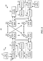
- FIG. 3 shows an alternative simplified functional block diagram of a communication device according to one embodiment of the invention.
- the communication device 300 in a wireless communication system can be utilized for realizing the UEs (or ATs) 116 and 122 in FIG. 1 , and the wireless communications system is preferably the LTE-A system.
- the communication device 300 may include an input device 302, an output device 304, a control circuit 306, a central processing unit (CPU) 308, a memory 310, a program code 312, and a transceiver 314.
- the control circuit 306 executes the program code 312 in the memory 310 through the CPU 308, thereby controlling an operation of the communications device 300.
- the communications device 300 can receive signals input by a user through the input device 302, such as a keyboard or keypad, and can output images and sounds through the output device 304, such as a monitor or speakers.
- the transceiver 314 is used to receive and transmit wireless signals, delivering received signals to the control circuit 306, and outputting signals generated by the control circuit 306 wirelessly.
- FIG. 4 is a simplified block diagram of the program code 312 shown in FIG. 3 in accordance with one embodiment of the invention.
- the program code 312 includes an application layer 400, a Layer 3 portion 402, and a Layer 2 portion 404, and is coupled to a Layer 1 portion 406.
- the Layer 3 portion 402 generally performs radio resource control.
- the Layer 2 portion 404 generally performs link control.
- the Layer 1 portion 406 generally performs physical connections.
- RP-101026 discusses some mechanism for protecting the CN (Core Network) from overloading due to MTC (Machine-type Communication). It has been identified that the total signaling from large numbers of MTC devices is a concern at least when an application requests many MTC devices to do "something" at the same time or when many MTC devices are roamers and their serving network fails, then they can all move onto the local competing networks, and potentially overload the not (yet) failed network(s). So, proposals have been made to introduce an additional establishment cause to allow RAN (Radio Access Network) node to differentiate low priority MTC traffic/signalling (and possibly other MTC traffic/signalling) from other traffic/signaling for both UMTS and LTE.
- RAN Radio Access Network
- MME Mobility Management Entity
- eNB Evolved Node B
- OVERLOAD START message When it becomes overloaded (as shown in FIG. 5A ).
- the eNB receiving the OVERLOAD START message shall assume the MME from which it receives the message as being in an overloaded state. If a UE (user equipment) attempts to gain access during the MME overloading, it is likely rejected by the eNB and enters the waiting period.
- the eNB can signal a value (may be called "wait time") to the UE and the value is used to decide the duration of the waiting period.
- time period which is implemented by a timer T302 can be found in TS 36.331 v9.4.0 and TS 36.331 v10.0.0.
- a longer wait time comparing to T302 could be used.
- the time period may be up to one hour according to S2-105318.
- eWaitTime a new parameter for wait time (may be called eWaitTime or "extended wait time" which is used to prevent a MTC device (using a cause, e.g. delay tolerant or low priority, indicated in a connection request or a connection setup complete message) from sending connection request in CN overload situation.
- the difference between T302 and eWaitTime is that eWaitTime has a larger maximum value.
- the eWaitTime may be included in a connection release message or a connection reject message. It is confirmed that the eWaitTime is handled at NAS (Non-Access Stratum) layer.
- the Mobility Management back-off timer corresponds to the eWaitTime in lower layers, e.g. RRC layer and is used for overload conditions. While the Mobility Management back-off timer is running, the UE shall not initiate any NAS request except for Service Users/emergency services.
- MME could notify the end of overloading to the eNB by OVERLOAD STOP message (as shown in FIG. 5B ).
- the eNB receiving the OVERLOAD STOP message shall assume that the overload situation at the MME from which it receives the message has ended and shall resume normal operation towards this MME. Since the eNB may not know when the MME overloading ends before receiving the OVERLOAD STOP message, the eNB may possibly give a conservative (e.g. relative longer) wait time to the UE. It can prevent the UE from making another attempt while the network is still overloading.
- the UE is informed about the end of CN overload through system information (as shown in FIG. 5C ).
- the UE is informed about the end of CN overload through a paging message (as shown in FIG. 5C ).
- the paging message could be a MTC (Machine-type Communication) specific message or a message addressed to a special RNTI (Radio Network Temporary Identifier) shared by a group of UEs.
- the UE may send connection request again tens of minutes after the relief of CN overload. Such a long waiting period after the relief of CN overload is unnecessary.
- One way to solve the issue is that eNB transmits a paging to inform the UE to send connection request for paging response.
- the UE is not allowed to send connection request when a timer corresponding to eWaitTime is running, like T302 is running. Adding some additional information in current paging message could be used to indicate the relief of CN overload.
- the message structure needs to be updated and the signalling overhead is increased.
- a UE would react to a paging message which pages the UE even when the UE is in the wait time due to eWaitTime .
- the UE considers the wait time due to eWaitTime as finished upon receiving a paging message which pages the UE.
- the UE performs any of the above actions upon receiving a special PDCCH signaling.
- eWaitTime e.g., a timer corresponding to eWaitTime in the UE is running
- the UE is allowed to initiate a RRC connection establishment procedure.
- the RRC connection establishment procedure is specified in TS 36.331 v10.0.0 and TS 25.331 v10.2.0.
- a UE when a UE is in a wait time due to eWaitTime , (e.g., a timer corresponding to eWaitTime in a UE is running) and the UE is paged by a paging message), the UE leaves the wait time (e.g., stops the timer).
- eWaitTime e.g., a timer corresponding to eWaitTime in a UE is running
- the UE leaves the wait time (e.g., stops the timer).
- the paging message does not include additional information (such as information related to CN overload).
- the paging message has the same content specified in TS 36.331 v10.0.0 or TS 25.331 v10.2.0.
- an establishment cause in a RRC connection request message (as specified in TS 36.331 v10.0.0 and TS 25.331 v10.2.0) corresponding to the connection establishment procedure is set to delay tolerant (or low priority).
- an indication in a RRC connection setup complete message (as specified in TS 36.331 v10.0.0 and TS 25.331 v10.2.0) corresponding to the connection establishment procedure is set to delay tolerant (or low priority).
- a method 600 for improving the wait time is shown in FIG. 6 .
- a UE Upon receiving a message indicating an eWaitTime , a UE enters and remains in a wait time period corresponding to the eWaitTime as shown in step 602.
- the eWaitTime is carried by a RRC Connection Reject message or a RRC Connection Release message.
- the wait time period is controlled by a timer that may be started upon receiving the eWaitTime .
- the UE is a MTC device, and may provide a delay tolerant or low priority indication to the network.
- the UE does not initiate a connection request with a specific cause.
- the specific cause could be delay tolerant or low priority.
- the UE receives a paging message that pages the UE.
- the UE performs a RRC Connection Establishment procedure (regardless of the wait time).
- the UE is allowed to initiate a connection request with a cause set to emergency during the wait time period and the wait time period is not affected (as discussed in TS 23.401 V10.2.0).
- the UE does not response to a paging message which does not page the UE.
- the establishment cause of the RRC Connection Establishment procedure may be set to mobile terminating calls. Additionally, the wait time period may not be affected (e.g., not considered as finished) due to the RRC Connection Establishment procedure.
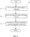
- FIG. 7 An alternative method 700 for improving the wait time according to one embodiment is shown in FIG. 7 .
- a UE Upon receiving a message indicating an eWaitTime , a UE enters and remains in a wait time period corresponding to an eWaitTime as shown in step 702.
- the eWaitTime is carried by a RRC Connection Reject message or a RRC Connection Release message.
- the wait time period is controlled by a timer that may be started upon receiving the eWaitTime .
- the UE is a MTC device, and may provide a delay tolerant or low priority indication to the network.
- the UE While in the wait time period, the UE does not initiate a connection request with a specific cause.
- the specific cause could be delay tolerant or low priority.
- the UE considers the wait time period as finished (e.g., stopping a timer corresponding to the wait time period) upon receiving a paging message that pages the UE.
- the UE initiates a RRC Connection Establishment procedure in response to the paging message.
- the establishment cause of the RRC Connection Establishment procedure may be set to mobile terminating calls.
- the UE is allowed to initiate a connection request with a cause set to emergency during the wait time period and the wait time period is not affected (as discussed in TS 23.401 V 10.2.0). Additionally, the UE does not consider the wait time period as finished when receiving a paging message which does not page the UE.
- the UE considers the wait time period as finished upon receiving a PDCCH (Physical Downlink Control Channel) signal.
- PDCCH Physical Downlink Control Channel
- the communication device 300 includes a program code 312 stored in memory 310.
- the CPU 308 executes the program code 312 to perform a method for log reporting according to various aspects of the disclosure as described above.
- the CPU 308 can also execute the program code 312 to perform all of the above-described actions and steps or others described herein.
- concurrent channels may be established based on pulse repetition frequencies.
- concurrent channels may be established based on pulse position or offsets.
- concurrent channels may be established based on time hopping sequences.
- concurrent channels may be established based on pulse repetition frequencies, pulse positions or offsets, and time hopping sequences.
- the various illustrative logical blocks, modules, and circuits described in connection with the aspects disclosed herein may be implemented within or performed by an integrated circuit ("IC"), an access terminal, or an access point.
- the IC may comprise a general purpose processor, a digital signal processor (DSP), an application specific integrated circuit (ASIC), a field programmable gate array (FPGA) or other programmable logic device, discrete gate or transistor logic, discrete hardware components, electrical components, optical components, mechanical components, or any combination thereof designed to perform the functions described herein, and may execute codes or instructions that reside within the IC, outside of the IC, or both.
- a general purpose processor may be a microprocessor, but in the alternative, the processor may be any conventional processor, controller, microcontroller, or state machine.
- a processor may also be implemented as a combination of computing devices, e.g., a combination of a DSP and a microprocessor, a plurality of microprocessors, one or more microprocessors in conjunction with a DSP core, or any other such configuration.
- a software module e.g., including executable instructions and related data
- other data may reside in a data memory such as RAM memory, flash memory, ROM memory, EPROM memory, EEPROM memory, registers, a hard disk, a removable disk, a CD-ROM, or any other form of computer-readable storage medium known in the art.
- a sample storage medium may be coupled to a machine such as, for example, a computer/processor (which may be referred to herein, for convenience, as a "processor") such the processor can read information (e.g., code) from and write information to the storage medium.
- a sample storage medium may be integral to the processor.
- the processor and the storage medium may reside in an ASIC.
- the ASIC may reside in user equipment.
- the processor and the storage medium may reside as discrete components in user equipment.
- any suitable computer-program product may comprise a computer-readable medium comprising codes relating to one or more of the aspects of the disclosure.
- a computer program product may comprise packaging materials.
Landscapes
- Engineering & Computer Science (AREA)
- Computer Networks & Wireless Communication (AREA)
- Signal Processing (AREA)
- Computer Security & Cryptography (AREA)
- Mobile Radio Communication Systems (AREA)
- Telephone Function (AREA)
Claims (9)
- Procédé d'amélioration de temps d'attente dans un système de communication sans fil comprenant le fait :de recevoir un message indiquant une valeur de temps d'attente dite eWaitTime au niveau d'un équipement utilisateur, UE ;d'entrer dans une période d'attente correspondant à la valeur eWaitTime, et d'empêcher l'initiation d'une demande de connexion avec une cause définie pour une tolérance au retard ou une faible priorité pendant la période d'attente, par l'UE ;dans lequel l'UE est autorisé à initier une demande de connexion avec une cause définie pour un cas d'urgence pendant la période d'attente et la période d'attente n'est pas affectée, etde considérer par l'UE, pendant la période d'attente, la période d'attente comme étant terminée suite à la réception d'un message de téléavertissement qui permet de téléavertir l'UE, et d'initier par l'UE une procédure d'établissement de connexion en réponse au message de téléavertissement qui permet de téléavertir l'UE.
- Procédé de la revendication 1, dans lequel l'UE considère la période d'attente comme n'étant pas terminée lors de la réception d'un message de téléavertissement qui ne permet pas de téléavertir l'UE.
- Procédé de l'une quelconque des revendications 1 à 2, dans lequel le message est un message de Rejet de Connexion RRC ou un message de Libération de Connexion RRC.
- Procédé de l'une quelconque des revendications 1 à 3, dans lequel le message de téléavertissement contient des informations de surcharge pour indiquer une fin de surcharge de CN.
- Procédé de l'une quelconque des revendications 1 à 4, dans lequel, la considération de la période d'attente comme étant terminée comprend l'arrêt par l'UE d'un temporisateur correspondant à la période d'attente.
- Procédé de l'une quelconque des revendications 1 à 5, dans lequel la période d'attente est commandée par un temporisateur.
- Procédé de l'une quelconque des revendications 1 à 6, dans lequel la période d'attente commence suite à la réception de la valeur eWaitTime.
- Dispositif de communication pour une utilisation dans un système de communication sans fil, le dispositif de communication comprenant :un circuit de commande (306) ;un processeur (308) installé dans le circuit de commande ; etune mémoire (310) installée dans le circuit de commande et couplée au processeur ;dans lequel le processeur est configuré pour exécuter un code de programme (312) stocké en mémoire pour effectuer les étapes de procédé selon l'une quelconque des revendications 1 à 7.
- Produit de programme informatique pouvant être chargé directement dans la mémoire (310) installée dans un circuit de commande (306) d'un dispositif de communication (300), comprenant des parties de code de programme pour effectuer les étapes de l'une quelconque des revendications 1 à 7 lorsque ledit produit est exécuté sur un processeur qui est installé dans le circuit de commande et couplé à la mémoire.
Applications Claiming Priority (2)
| Application Number | Priority Date | Filing Date | Title |
|---|---|---|---|
| US201061425688P | 2010-12-21 | 2010-12-21 | |
| US201161444301P | 2011-02-18 | 2011-02-18 |
Publications (2)
| Publication Number | Publication Date |
|---|---|
| EP2469958A1 EP2469958A1 (fr) | 2012-06-27 |
| EP2469958B1 true EP2469958B1 (fr) | 2017-11-01 |
Family
ID=45445709
Family Applications (1)
| Application Number | Title | Priority Date | Filing Date |
|---|---|---|---|
| EP11009965.2A Active EP2469958B1 (fr) | 2010-12-21 | 2011-12-19 | Procédé et appareil pour améliorer le temps d'attente dans un système de communications sans fil |
Country Status (6)
| Country | Link |
|---|---|
| US (1) | US8903352B2 (fr) |
| EP (1) | EP2469958B1 (fr) |
| JP (1) | JP5383783B2 (fr) |
| KR (1) | KR101366231B1 (fr) |
| CN (1) | CN103096472B (fr) |
| TW (1) | TWI452923B (fr) |
Families Citing this family (16)
| Publication number | Priority date | Publication date | Assignee | Title |
|---|---|---|---|---|
| SG153685A1 (en) * | 2007-12-17 | 2009-07-29 | Univ Nanyang | Peer-to-peer communication in wireless sensor network through delay response between packets |
| US9198216B2 (en) * | 2011-01-07 | 2015-11-24 | Broadcom Corporation | Wait timer for delay tolerant terminal |
| CN102111847B (zh) * | 2011-01-10 | 2013-07-24 | 大唐移动通信设备有限公司 | 一种接入控制的方法及装置 |
| BR112013019363B1 (pt) | 2011-02-10 | 2021-11-16 | Nokia Technologies Oy | Método, aparelho e meio legível por computador não transitório que contém instruções |
| WO2012154325A1 (fr) * | 2011-04-01 | 2012-11-15 | Interdigital Patent Holdings, Inc. | Procédé et appareil pour la commande de la connectivité à un réseau |
| EP2764641B1 (fr) * | 2011-10-03 | 2019-12-18 | Intel Corporation | Mécanismes de communication de dispositif à dispositif (d2d) |
| US9241351B2 (en) | 2011-11-04 | 2016-01-19 | Intel Corporation | Techniques and configurations for triggering a plurality of wireless devices |
| PL2807897T3 (pl) * | 2012-01-23 | 2017-10-31 | Deutsche Telekom Ag | Sposób stosowania wyposażenia użytkownika z pierwszą publiczną naziemną siecią telefonii komórkowej oraz z drugą publiczną naziemną siecią telefonii komórkowej, wyposażenie użytkownika, program oraz produkt w postaci programu komputerowego |
| KR20160044048A (ko) * | 2012-10-05 | 2016-04-22 | 엘지전자 주식회사 | 무선 통신 시스템에서 다중 우선순위 제어 방법 및 장치 |
| US20160134464A1 (en) * | 2013-07-09 | 2016-05-12 | Telefonaktiebolaget L M Ericsson (Publ) | Core network node, radio access network node and methods therein for controlling overload in core network |
| EP2869648B1 (fr) | 2013-10-31 | 2020-07-08 | Alcatel Lucent | Réponse à des requêtes de radiomessagerie en attente pour demander une connexion à un réseau sans fil |
| US9049609B1 (en) * | 2014-02-25 | 2015-06-02 | Sprint Spectrum L.P. | Dynamic management of retry time period based on past lack of support for providing a service |
| US9497771B2 (en) * | 2014-04-18 | 2016-11-15 | Apple Inc. | Deterministic RRC connections |
| US10375646B2 (en) * | 2014-04-18 | 2019-08-06 | Apple Inc. | Coordination between application and baseband layer operation |
| US9906977B2 (en) | 2014-04-18 | 2018-02-27 | Apple Inc. | Deterministic RRC connections |
| US20220210698A1 (en) * | 2019-04-30 | 2022-06-30 | Convida Wireless, Llc | Electronic device and methods for performing data aggregation in a 5g user equipment |
Family Cites Families (10)
| Publication number | Priority date | Publication date | Assignee | Title |
|---|---|---|---|---|
| US7167458B2 (en) * | 2002-05-30 | 2007-01-23 | Qualcomm, Incorporated | Method and apparatus for determining a number of times a message is transmitted on a paging channel to a mobile station |
| CN100334908C (zh) * | 2004-08-04 | 2007-08-29 | 财团法人资讯工业策进会 | 用于无线通信网路中的行动通信装置的省电方法 |
| JP4421459B2 (ja) | 2004-11-30 | 2010-02-24 | 株式会社東芝 | 無線通信装置及び無線通信方法 |
| JP4651478B2 (ja) | 2005-08-02 | 2011-03-16 | 株式会社エヌ・ティ・ティ・ドコモ | 無線アクセス制御装置、移動局及び方法 |
| JP2007266725A (ja) * | 2006-03-27 | 2007-10-11 | Fujitsu Ltd | 移動管理装置および移動管理方法 |
| CN101242645B (zh) * | 2007-02-09 | 2011-02-09 | 华为技术有限公司 | 移动终端从空闲态进入激活态的方法及系统 |
| JP4979632B2 (ja) | 2007-05-18 | 2012-07-18 | イノヴァティヴ ソニック リミテッド | 無線通信システムにおいて待ち行列機能を管理する方法及び装置 |
| CN101415147B (zh) * | 2007-10-19 | 2011-04-13 | 华为技术有限公司 | 一种用户设备寻呼方法及设备 |
| CN102017776B (zh) | 2008-04-28 | 2014-09-03 | 富士通株式会社 | 无线通信系统中的连接处理方法、无线基站以及无线终端 |
| ES2368385T3 (es) | 2009-01-29 | 2011-11-16 | Lg Electronics Inc. | Esquema de transmisión de señales para una gestión eficaz del canal dedicado mejorado común. |
-
2011
- 2011-12-19 EP EP11009965.2A patent/EP2469958B1/fr active Active
- 2011-12-20 US US13/331,345 patent/US8903352B2/en active Active
- 2011-12-20 JP JP2011277854A patent/JP5383783B2/ja active Active
- 2011-12-21 CN CN201110433589.0A patent/CN103096472B/zh active Active
- 2011-12-21 KR KR1020110139222A patent/KR101366231B1/ko active IP Right Grant
- 2011-12-21 TW TW100147692A patent/TWI452923B/zh active
Non-Patent Citations (1)
| Title |
|---|
| None * |
Also Published As
| Publication number | Publication date |
|---|---|
| KR101366231B1 (ko) | 2014-02-21 |
| TWI452923B (zh) | 2014-09-11 |
| TW201228446A (en) | 2012-07-01 |
| CN103096472A (zh) | 2013-05-08 |
| JP5383783B2 (ja) | 2014-01-08 |
| KR20120070530A (ko) | 2012-06-29 |
| JP2012134973A (ja) | 2012-07-12 |
| CN103096472B (zh) | 2016-08-31 |
| US20120157033A1 (en) | 2012-06-21 |
| US8903352B2 (en) | 2014-12-02 |
| EP2469958A1 (fr) | 2012-06-27 |
Similar Documents
| Publication | Publication Date | Title |
|---|---|---|
| EP2469958B1 (fr) | Procédé et appareil pour améliorer le temps d'attente dans un système de communications sans fil | |
| CN109041245B (zh) | 无线通信系统中多个调度请求配置的方法和设备 | |
| US20210211994A1 (en) | Method and apparatus for triggering and canceling power headroom report (phr) in small data transmission procedure in a wireless communication system | |
| US9380484B2 (en) | Method and apparatus to prevent radio access network (RAN) overload in a wireless communication system | |
| EP2919524B1 (fr) | Procédé et appareil permettant de mettre en uvre un service dispositif-à-dispositif (d2d) dans un système de communication sans fil | |
| EP2822333B1 (fr) | Procédé et dispositif d'améliorations de petites cellules dans un système de communication sans fil | |
| US11496886B2 (en) | Method and apparatus for connection control in a wireless communication system | |
| EP2931001B1 (fr) | Procédé et appareil permettant de rapporter l'état de la mémoire tampon pour une communication de dispositif à dispositif dans un système de communication sans fil | |
| EP2600680B1 (fr) | Procédé et appareil pour reconfigurer le fonctionnement semi-persistant (sps) dans un système de communication sans fil | |
| JP2020088853A (ja) | 無線通信システムにおいて事前設定された上りリンクリソースの設定を解除するための方法および装置 | |
| EP2688357B1 (fr) | Procédé et appareil de réduction de l'effort de signalisation dans un réseau de communication sans fil | |
| CN114205920B (zh) | 无线通信系统中用于小数据传送程序的方法和设备 | |
| EP2665328A1 (fr) | Procédé et appareil d'enregistrement des cas d'un UE ne parvenant pas à établir une connexion dans un réseau de communication sans fil | |
| CN113950153A (zh) | 选择预配置小数据传送中后续传送带宽部分的方法和设备 | |
| US11910482B2 (en) | Method and apparatus for UE reporting for multi-USIM in a wireless communication system | |
| US20120307632A1 (en) | Method and apparatus to prevent ran (radio access network) overload for legacy networks in a wireless communication system | |
| EP2706794B1 (fr) | Procédé et appareil pour indiquer des préférences de puissance (ppi) dans un système de communication sans fil | |
| CN115989714A (zh) | 验证处于非活动状态的预配置资源 | |
| EP4062701A1 (fr) | Rapport de statut de tampon de liaison latérale | |
| WO2022031718A1 (fr) | Radiomessagerie de dispositif sans fil | |
| EP2665322A2 (fr) | Procédé et appareil d'amélioration de priorisation de fréquences dans un réseau de communication sans fil | |
| KR101365629B1 (ko) | 무선 통신 시스템에서 로그 리포팅을 위한 방법 및 장치 |
Legal Events
| Date | Code | Title | Description |
|---|---|---|---|
| AK | Designated contracting states |
Kind code of ref document: A1 Designated state(s): AL AT BE BG CH CY CZ DE DK EE ES FI FR GB GR HR HU IE IS IT LI LT LU LV MC MK MT NL NO PL PT RO RS SE SI SK SM TR |
|
| AX | Request for extension of the european patent |
Extension state: BA ME |
|
| PUAI | Public reference made under article 153(3) epc to a published international application that has entered the european phase |
Free format text: ORIGINAL CODE: 0009012 |
|
| 17P | Request for examination filed |
Effective date: 20120725 |
|
| RAP1 | Party data changed (applicant data changed or rights of an application transferred) |
Owner name: INNOVATIVE SONIC CORPORATION |
|
| 17Q | First examination report despatched |
Effective date: 20160623 |
|
| GRAJ | Information related to disapproval of communication of intention to grant by the applicant or resumption of examination proceedings by the epo deleted |
Free format text: ORIGINAL CODE: EPIDOSDIGR1 |
|
| GRAP | Despatch of communication of intention to grant a patent |
Free format text: ORIGINAL CODE: EPIDOSNIGR1 |
|
| RIC1 | Information provided on ipc code assigned before grant |
Ipc: H04W 74/04 20090101AFI20170404BHEP Ipc: H04W 76/02 20090101ALN20170404BHEP |
|
| INTG | Intention to grant announced |
Effective date: 20170424 |
|
| GRAS | Grant fee paid |
Free format text: ORIGINAL CODE: EPIDOSNIGR3 |
|
| GRAJ | Information related to disapproval of communication of intention to grant by the applicant or resumption of examination proceedings by the epo deleted |
Free format text: ORIGINAL CODE: EPIDOSDIGR1 |
|
| GRAL | Information related to payment of fee for publishing/printing deleted |
Free format text: ORIGINAL CODE: EPIDOSDIGR3 |
|
| GRAR | Information related to intention to grant a patent recorded |
Free format text: ORIGINAL CODE: EPIDOSNIGR71 |
|
| RIN1 | Information on inventor provided before grant (corrected) |
Inventor name: OU, MENG-HUI Inventor name: GUO, YU-HSUAN |
|
| GRAA | (expected) grant |
Free format text: ORIGINAL CODE: 0009210 |
|
| RAP1 | Party data changed (applicant data changed or rights of an application transferred) |
Owner name: INNOVATIVE SONIC CORPORATION |
|
| INTC | Intention to grant announced (deleted) | ||
| RIN1 | Information on inventor provided before grant (corrected) |
Inventor name: OU, MENG-HUI Inventor name: GUO, YU-HSUAN |
|
| AK | Designated contracting states |
Kind code of ref document: B1 Designated state(s): AL AT BE BG CH CY CZ DE DK EE ES FI FR GB GR HR HU IE IS IT LI LT LU LV MC MK MT NL NO PL PT RO RS SE SI SK SM TR |
|
| INTG | Intention to grant announced |
Effective date: 20170926 |
|
| REG | Reference to a national code |
Ref country code: GB Ref legal event code: FG4D |
|
| RIC1 | Information provided on ipc code assigned before grant |
Ipc: H04W 74/04 20090101AFI20170922BHEP Ipc: H04W 76/02 20090101ALN20170922BHEP |
|
| REG | Reference to a national code |
Ref country code: CH Ref legal event code: EP Ref country code: AT Ref legal event code: REF Ref document number: 943209 Country of ref document: AT Kind code of ref document: T Effective date: 20171115 |
|
| REG | Reference to a national code |
Ref country code: IE Ref legal event code: FG4D |
|
| REG | Reference to a national code |
Ref country code: DE Ref legal event code: R096 Ref document number: 602011042831 Country of ref document: DE |
|
| REG | Reference to a national code |
Ref country code: FR Ref legal event code: PLFP Year of fee payment: 7 |
|
| REG | Reference to a national code |
Ref country code: NL Ref legal event code: FP |
|
| REG | Reference to a national code |
Ref country code: LT Ref legal event code: MG4D |
|
| REG | Reference to a national code |
Ref country code: AT Ref legal event code: MK05 Ref document number: 943209 Country of ref document: AT Kind code of ref document: T Effective date: 20171101 |
|
| PG25 | Lapsed in a contracting state [announced via postgrant information from national office to epo] |
Ref country code: ES Free format text: LAPSE BECAUSE OF FAILURE TO SUBMIT A TRANSLATION OF THE DESCRIPTION OR TO PAY THE FEE WITHIN THE PRESCRIBED TIME-LIMIT Effective date: 20171101 Ref country code: LT Free format text: LAPSE BECAUSE OF FAILURE TO SUBMIT A TRANSLATION OF THE DESCRIPTION OR TO PAY THE FEE WITHIN THE PRESCRIBED TIME-LIMIT Effective date: 20171101 Ref country code: NO Free format text: LAPSE BECAUSE OF FAILURE TO SUBMIT A TRANSLATION OF THE DESCRIPTION OR TO PAY THE FEE WITHIN THE PRESCRIBED TIME-LIMIT Effective date: 20180201 Ref country code: FI Free format text: LAPSE BECAUSE OF FAILURE TO SUBMIT A TRANSLATION OF THE DESCRIPTION OR TO PAY THE FEE WITHIN THE PRESCRIBED TIME-LIMIT Effective date: 20171101 Ref country code: SE Free format text: LAPSE BECAUSE OF FAILURE TO SUBMIT A TRANSLATION OF THE DESCRIPTION OR TO PAY THE FEE WITHIN THE PRESCRIBED TIME-LIMIT Effective date: 20171101 |
|
| PG25 | Lapsed in a contracting state [announced via postgrant information from national office to epo] |
Ref country code: BG Free format text: LAPSE BECAUSE OF FAILURE TO SUBMIT A TRANSLATION OF THE DESCRIPTION OR TO PAY THE FEE WITHIN THE PRESCRIBED TIME-LIMIT Effective date: 20180201 Ref country code: IS Free format text: LAPSE BECAUSE OF FAILURE TO SUBMIT A TRANSLATION OF THE DESCRIPTION OR TO PAY THE FEE WITHIN THE PRESCRIBED TIME-LIMIT Effective date: 20180301 Ref country code: LV Free format text: LAPSE BECAUSE OF FAILURE TO SUBMIT A TRANSLATION OF THE DESCRIPTION OR TO PAY THE FEE WITHIN THE PRESCRIBED TIME-LIMIT Effective date: 20171101 Ref country code: RS Free format text: LAPSE BECAUSE OF FAILURE TO SUBMIT A TRANSLATION OF THE DESCRIPTION OR TO PAY THE FEE WITHIN THE PRESCRIBED TIME-LIMIT Effective date: 20171101 Ref country code: AT Free format text: LAPSE BECAUSE OF FAILURE TO SUBMIT A TRANSLATION OF THE DESCRIPTION OR TO PAY THE FEE WITHIN THE PRESCRIBED TIME-LIMIT Effective date: 20171101 Ref country code: GR Free format text: LAPSE BECAUSE OF FAILURE TO SUBMIT A TRANSLATION OF THE DESCRIPTION OR TO PAY THE FEE WITHIN THE PRESCRIBED TIME-LIMIT Effective date: 20180202 Ref country code: HR Free format text: LAPSE BECAUSE OF FAILURE TO SUBMIT A TRANSLATION OF THE DESCRIPTION OR TO PAY THE FEE WITHIN THE PRESCRIBED TIME-LIMIT Effective date: 20171101 |
|
| PG25 | Lapsed in a contracting state [announced via postgrant information from national office to epo] |
Ref country code: CZ Free format text: LAPSE BECAUSE OF FAILURE TO SUBMIT A TRANSLATION OF THE DESCRIPTION OR TO PAY THE FEE WITHIN THE PRESCRIBED TIME-LIMIT Effective date: 20171101 Ref country code: SK Free format text: LAPSE BECAUSE OF FAILURE TO SUBMIT A TRANSLATION OF THE DESCRIPTION OR TO PAY THE FEE WITHIN THE PRESCRIBED TIME-LIMIT Effective date: 20171101 Ref country code: CY Free format text: LAPSE BECAUSE OF FAILURE TO SUBMIT A TRANSLATION OF THE DESCRIPTION OR TO PAY THE FEE WITHIN THE PRESCRIBED TIME-LIMIT Effective date: 20171101 Ref country code: EE Free format text: LAPSE BECAUSE OF FAILURE TO SUBMIT A TRANSLATION OF THE DESCRIPTION OR TO PAY THE FEE WITHIN THE PRESCRIBED TIME-LIMIT Effective date: 20171101 Ref country code: DK Free format text: LAPSE BECAUSE OF FAILURE TO SUBMIT A TRANSLATION OF THE DESCRIPTION OR TO PAY THE FEE WITHIN THE PRESCRIBED TIME-LIMIT Effective date: 20171101 |
|
| REG | Reference to a national code |
Ref country code: CH Ref legal event code: PL |
|
| REG | Reference to a national code |
Ref country code: DE Ref legal event code: R097 Ref document number: 602011042831 Country of ref document: DE |
|
| PG25 | Lapsed in a contracting state [announced via postgrant information from national office to epo] |
Ref country code: IT Free format text: LAPSE BECAUSE OF FAILURE TO SUBMIT A TRANSLATION OF THE DESCRIPTION OR TO PAY THE FEE WITHIN THE PRESCRIBED TIME-LIMIT Effective date: 20171101 Ref country code: RO Free format text: LAPSE BECAUSE OF FAILURE TO SUBMIT A TRANSLATION OF THE DESCRIPTION OR TO PAY THE FEE WITHIN THE PRESCRIBED TIME-LIMIT Effective date: 20171101 Ref country code: PL Free format text: LAPSE BECAUSE OF FAILURE TO SUBMIT A TRANSLATION OF THE DESCRIPTION OR TO PAY THE FEE WITHIN THE PRESCRIBED TIME-LIMIT Effective date: 20171101 Ref country code: SM Free format text: LAPSE BECAUSE OF FAILURE TO SUBMIT A TRANSLATION OF THE DESCRIPTION OR TO PAY THE FEE WITHIN THE PRESCRIBED TIME-LIMIT Effective date: 20171101 |
|
| PLBE | No opposition filed within time limit |
Free format text: ORIGINAL CODE: 0009261 |
|
| STAA | Information on the status of an ep patent application or granted ep patent |
Free format text: STATUS: NO OPPOSITION FILED WITHIN TIME LIMIT |
|
| REG | Reference to a national code |
Ref country code: IE Ref legal event code: MM4A |
|
| PG25 | Lapsed in a contracting state [announced via postgrant information from national office to epo] |
Ref country code: MT Free format text: LAPSE BECAUSE OF NON-PAYMENT OF DUE FEES Effective date: 20171219 Ref country code: LU Free format text: LAPSE BECAUSE OF NON-PAYMENT OF DUE FEES Effective date: 20171219 |
|
| 26N | No opposition filed |
Effective date: 20180802 |
|
| REG | Reference to a national code |
Ref country code: BE Ref legal event code: MM Effective date: 20171231 |
|
| PG25 | Lapsed in a contracting state [announced via postgrant information from national office to epo] |
Ref country code: IE Free format text: LAPSE BECAUSE OF NON-PAYMENT OF DUE FEES Effective date: 20171219 |
|
| PG25 | Lapsed in a contracting state [announced via postgrant information from national office to epo] |
Ref country code: LI Free format text: LAPSE BECAUSE OF NON-PAYMENT OF DUE FEES Effective date: 20171231 Ref country code: CH Free format text: LAPSE BECAUSE OF NON-PAYMENT OF DUE FEES Effective date: 20171231 Ref country code: SI Free format text: LAPSE BECAUSE OF FAILURE TO SUBMIT A TRANSLATION OF THE DESCRIPTION OR TO PAY THE FEE WITHIN THE PRESCRIBED TIME-LIMIT Effective date: 20171101 Ref country code: BE Free format text: LAPSE BECAUSE OF NON-PAYMENT OF DUE FEES Effective date: 20171231 |
|
| PG25 | Lapsed in a contracting state [announced via postgrant information from national office to epo] |
Ref country code: MC Free format text: LAPSE BECAUSE OF FAILURE TO SUBMIT A TRANSLATION OF THE DESCRIPTION OR TO PAY THE FEE WITHIN THE PRESCRIBED TIME-LIMIT Effective date: 20171101 Ref country code: HU Free format text: LAPSE BECAUSE OF FAILURE TO SUBMIT A TRANSLATION OF THE DESCRIPTION OR TO PAY THE FEE WITHIN THE PRESCRIBED TIME-LIMIT; INVALID AB INITIO Effective date: 20111219 |
|
| PG25 | Lapsed in a contracting state [announced via postgrant information from national office to epo] |
Ref country code: MK Free format text: LAPSE BECAUSE OF FAILURE TO SUBMIT A TRANSLATION OF THE DESCRIPTION OR TO PAY THE FEE WITHIN THE PRESCRIBED TIME-LIMIT Effective date: 20171101 |
|
| PG25 | Lapsed in a contracting state [announced via postgrant information from national office to epo] |
Ref country code: TR Free format text: LAPSE BECAUSE OF FAILURE TO SUBMIT A TRANSLATION OF THE DESCRIPTION OR TO PAY THE FEE WITHIN THE PRESCRIBED TIME-LIMIT Effective date: 20171101 |
|
| PG25 | Lapsed in a contracting state [announced via postgrant information from national office to epo] |
Ref country code: PT Free format text: LAPSE BECAUSE OF FAILURE TO SUBMIT A TRANSLATION OF THE DESCRIPTION OR TO PAY THE FEE WITHIN THE PRESCRIBED TIME-LIMIT Effective date: 20171101 |
|
| PG25 | Lapsed in a contracting state [announced via postgrant information from national office to epo] |
Ref country code: AL Free format text: LAPSE BECAUSE OF FAILURE TO SUBMIT A TRANSLATION OF THE DESCRIPTION OR TO PAY THE FEE WITHIN THE PRESCRIBED TIME-LIMIT Effective date: 20171101 |
|
| P01 | Opt-out of the competence of the unified patent court (upc) registered |
Effective date: 20230509 |
|
| PGFP | Annual fee paid to national office [announced via postgrant information from national office to epo] |
Ref country code: GB Payment date: 20231115 Year of fee payment: 13 |
|
| PGFP | Annual fee paid to national office [announced via postgrant information from national office to epo] |
Ref country code: NL Payment date: 20231226 Year of fee payment: 13 Ref country code: FR Payment date: 20231115 Year of fee payment: 13 Ref country code: DE Payment date: 20231115 Year of fee payment: 13 |