EP2469867A2 - Bildverarbeitungsvorrichtung und Bildverarbeitungsverfahren - Google Patents
Bildverarbeitungsvorrichtung und Bildverarbeitungsverfahren Download PDFInfo
- Publication number
- EP2469867A2 EP2469867A2 EP11192541A EP11192541A EP2469867A2 EP 2469867 A2 EP2469867 A2 EP 2469867A2 EP 11192541 A EP11192541 A EP 11192541A EP 11192541 A EP11192541 A EP 11192541A EP 2469867 A2 EP2469867 A2 EP 2469867A2
- Authority
- EP
- European Patent Office
- Prior art keywords
- image
- eye
- externally
- images
- taken
- Prior art date
- Legal status (The legal status is an assumption and is not a legal conclusion. Google has not performed a legal analysis and makes no representation as to the accuracy of the status listed.)
- Withdrawn
Links
Images


Classifications
-
- H—ELECTRICITY
- H04—ELECTRIC COMMUNICATION TECHNIQUE
- H04N—PICTORIAL COMMUNICATION, e.g. TELEVISION
- H04N13/00—Stereoscopic video systems; Multi-view video systems; Details thereof
- H04N13/20—Image signal generators
- H04N13/261—Image signal generators with monoscopic-to-stereoscopic image conversion
-
- H—ELECTRICITY
- H04—ELECTRIC COMMUNICATION TECHNIQUE
- H04N—PICTORIAL COMMUNICATION, e.g. TELEVISION
- H04N13/00—Stereoscopic video systems; Multi-view video systems; Details thereof
- H04N13/10—Processing, recording or transmission of stereoscopic or multi-view image signals
- H04N13/106—Processing image signals
- H04N13/111—Transformation of image signals corresponding to virtual viewpoints, e.g. spatial image interpolation
-
- H—ELECTRICITY
- H04—ELECTRIC COMMUNICATION TECHNIQUE
- H04N—PICTORIAL COMMUNICATION, e.g. TELEVISION
- H04N13/00—Stereoscopic video systems; Multi-view video systems; Details thereof
- H04N13/10—Processing, recording or transmission of stereoscopic or multi-view image signals
- H04N13/106—Processing image signals
- H04N13/128—Adjusting depth or disparity
Definitions
- the present technology relates to an image processing apparatus and an image processing method for processing a signal of an image which can be three-dimensionally viewed by a viewer.
- a 3D image which can be three-dimensionally viewed can be provided to an observer by displaying images having parallax to right and left eyes of the observer. It has been expected that a 3D image technique is applied to various fields such as television broadcast, movies, telecommunication, and telemedicine.
- a time-division stereoscopic image display system that is composed of a combination of a display device and 3D glasses has already been widespread (For example, refer to Japanese Unexamined Patent Application Publication No. 2010-21731 ).
- the display device displays a left-eye image and a right-eye image which have parallax alternately on a screen in a particularly short cycle.
- the 3D glasses have shutter mechanisms which are liquid crystal lenses, for example, and provided to a left-eye part and a right-eye part respectively.
- 3D glasses of the number of persons who watch contents at the same time should be provided, a person who usually wears glasses has to further wear 3D glasses on the glasses, eyestrain is easily caused by long-time viewing, and a viewed image changes in accordance with a move of a viewpoint of a viewer.
- it is troublesome to carry shutter glasses as well when we would like to enjoy 3D images on portable information equipment such as a portable disk reproduction device which performs reproduction processing of a disk in which 3D video contents are recorded.
- An image which is three-dimensionally viewed is basically an actually-taken two-viewpoint image which is composed of a left-eye image and a right-eye image which are obtained by actually taking an object respectively by a left-eye camera and a right-eye camera.
- the number of viewpoints is increased as four viewpoints or eight viewpoints, for example, and parallax images which are taken from larger number of directions are combined, a more natural three-dimensional image can be viewed not only from the front but also from wider viewpoints.
- a multi-viewpoint image is composed of images which are actually taken from multiple viewpoints by a plurality of cameras (multi-viewpoint cameras) which are arranged in an array fashion.
- the number of multi-viewpoint cameras is increased in accordance with the increase of the number of viewpoints, so that the cost of contents production including shooting is increased and a data amount of the contents is increased disadvantageously.
- the increase of the data amount causes increase of memory, increase of a circuit scale, and the like when 3D images are dealt in portable information equipment such as a portable disk reproduction apparatus, deteriorating portability.
- the approach described herein helps to provide a superior image processing apparatus and a superior image processing method by which a multi-viewpoint image for obtaining a three-dimensional image which can be three-dimensionally viewed with naked eyes can be favorably processed.
- the approach described herein helps to provide a superior image processing apparatus and a superior image processing method by which a multi-viewpoint image can be processed with smaller memory capacity and smaller circuit scale.
- an image processing apparatus generating a multi-viewpoint image, including a parallax detection unit configured to receive only one of a plurality of actually-taken images including a left-eye image taken by a left-eye camera and a right-eye image taken by a right-eye camera and detect parallax of the received image so as to generate a parallax map, a first pseudo three-dimensional image generation unit configured to receive the left-eye image taken by the left-eye camera and generate one or more externally-provided or internally-provided images that are taken by a camera externally or internally provided to the left-eye camera, based on the parallax map generated by the parallax detection unit, a first delay unit configured to receive the left-eye image taken by the left-eye camera and output the left-eye image with elapse of delay time that corresponds to time during which the first pseudo three-dimensional image generation unit generates one of the externally-provided images and the internally-provided images, a second pseudo
- the image processing apparatus of the above embodiment may further include an image composition unit configured to discretely arrange respective pixels of the generated images of multiple viewpoints so as to compose a three-dimensional image.
- an image processing method generating a multi-viewpoint image, including detecting parallax from only one of a plurality of actually-taken images including a left-eye image taken by a left-eye camera and a right-eye image taken by a right-eye camera so as to generate a parallax map, generating one or more externally-provided or internally-provided images that are taken by a camera externally or internally provided to the left-eye camera, from the left-eye image taken by the left-eye camera, based on the parallax map that is generated in detecting parallax, outputting the left-eye image taken by the left-eye camera with elapse of delay time that corresponds to time during which one of the externally-provided images and the internally-provided images is generated in generating one or more externally-provided or internally-provided images from the left-eye image, generating one or more externally-provided or internally-provided images that are taken by a camera externally or
- a superior image processing apparatus and a superior image processing method by which a multi-viewpoint image for obtaining a three-dimensional image which can be three-dimensionally viewed with naked eyes can be favorably processed can be provided.
- a superior image processing apparatus in which a circuit for generating a multi-viewpoint image from left and right actually-taken images is configured to have a smaller circuit scale and smaller memory capacity can be provided.
- the present approach can be used in an image processing apparatus and an image processing method for processing an image which is pseudo-3D-generated so as to obtain a three dimensional image which can be viewed with naked eyes.
- one composite image is generated by discretely arranging respective pixels of images of multiple viewpoints, a viewer with naked eyes can percept a three-dimensional image.
- a left-eye image and a right-eye image which are respectively acquired by a left-eye camera and a right-eye camera are used as actually-taken images and pseudo 3D generation processing is applied to these actually-taken images so as to obtain an externally-provided image and multi-viewpoint-convert the images of two viewpoints.
- the pseudo 3D generation processing indicates that depth (parallax) information is obtained from still images taken on two viewpoints for images respectively taken by a left-eye camera and a right-eye camera so as to falsely generate images of multiple viewpoints.
- Processing respectively performed to the left-eye image and the right-eye image is similar to 2D/3D conversion in which depths of respective objects in a two-dimensional image are estimated so as to convert the image into a pseudo three-dimensional video image.
- Figs. 3A and 3B schematically illustrate a system of multi-viewpoint conversion processing in which images of two viewpoints are converted into images of four viewpoints by using pseudo 3D generation.
- L and R are respectively real left-eye camera and right-eye camera and a left-eye actually-taken image L and a right-eye actually-taken image R can be obtained from respective cameras.
- an externally-provided image "(LL) left-left” which is taken from a pseudo camera externally provided to the left-eye camera L mentioned above and an internally-provided image "(LR) left-right” which is taken from a pseudo camera internally provided to the left-eye camera L can be obtained.
- an externally-provided image "(RR) right-right” which is taken from a pseudo camera externally provided to the right-eye camera R mentioned above and an internally-provided image "(RL) right-left” which is taken from a pseudo camera internally provided to the right-eye camera R can be obtained.
- intervals of respective cameras LL, L, LR, RL, R, and RR may be uniform.
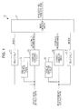
- Fig. 1 schematically illustrates the functional configuration of an image processing circuit 10 that generates four viewpoints by pseudo 3D generation from a left-eye image L and a right-eye image R which are respectively acquired by an actual take by a left-eye camera and a right-eye camera.
- a parallax detection circuit 12 When a parallax detection circuit 12 receives the left-eye image L, the parallax detection circuit 12 detects depths, that is, parallax of respective pixels and generates a parallax map for one image frame, for example, so as to output the parallax map to a pseudo 3D generation circuit 13.
- the pseudo 3D generation circuit 13 generates an externally-provided image from an actual-taken image based on parallax information. Namely, when the pseudo 3D generation circuit 13 receives the left-eye image L, the pseudo 3D generation circuit 13 generates an externally-provided image LL which seems to be taken by a pseudo camera externally provided to the left-eye camera L, based on the above-mentioned parallax map. As the processing of the pseudo 3D generation, enhancement such as enhancing a left edge based on the parallax information is applied, for example, so as to generate the image LL which seems to be taken by the pseudo camera externally provided to the left-eye camera L.
- the delay circuit 11 When a delay circuit 11 receives the left-eye image L, the delay circuit 11 outputs the left-eye image L with elapse of delay time during which the pseudo 3D generation circuit 13 generates the externally-provided image LL from the left-eye image L and outputs the image LL.
- a parallax detection circuit 15 receives the right-eye image R, the parallax detection circuit 15 detects depths, that is, parallax of respective pixels and generates a parallax map for one image frame, for example, so as to output the parallax map to a pseudo 3D generation circuit 16.
- the pseudo 3D generation circuit 16 When the pseudo 3D generation circuit 16 receives the right-eye image R, the pseudo 3D generation circuit 16 generates an image RR which seems to be taken by a pseudo camera externally provided to the right-eye camera R, based on the above-mentioned parallax map.
- enhancement such as enhancing a right edge based on the parallax information is applied, for example, so as to generate the image RR which seems to be taken by the pseudo camera externally provided to the right-eye camera R.
- the delay circuit 14 When a delay circuit 14 receives the right-eye image R, the delay circuit 14 outputs the right-eye image R with elapse of delay time during which the pseudo 3D generation circuit 16 generates the externally-provided image RR from the right-eye image R and outputs the image RR.
- an image composition circuit 17 When an image composition circuit 17 receives the above-described images L, LL, RR, and R of four viewpoints, the image composition circuit 17 discretely arranges respective pixels of these images based on a predetermined rule so as to generate and output one composite image.
- the image composition circuit 17 can arbitrarily arrange pixels perform pixel arrangement accompanying parallax adjustment.
- the arrangement method of pixels of respective viewpoint images is not directly related to the substance of embodiments of the present technology, so that its detailed description is not shown in this specification.
- the composite image obtained by the image composition circuit 17 is outputted to a screen of a display device such as a liquid crystal display, as a 3D image which can be three-dimensionally viewed by naked eyes.
- a display device such as a liquid crystal display
- the composite image is stored in a recording medium after undergoing predetermined signal processing such as encoding.
- the image processing circuit 10 shown in Fig. 1 has such configuration that the two pseudo 3D generation circuits 13 and 16 are arranged in parallel so as to generate four pieces of parallax data. Further, the image processing circuit 10 includes the parallax detection circuits 12 and 15 which respectively perform parallax detection processing with respect to the left-eye image L and the right-eye image R so as to generate parallax maps, and the pseudo 3D generation circuits 13 and 16 respectively generate externally-provided images LL and RR by using the parallax maps separately generated from the left-eye image L and the right-eye image R respectively.
- the parallax detection circuit 12 for the left-eye image L and the parallax detection circuit 15 for the right-eye image R have to be separately provided, increasing the circuit scale disadvantageously.
- a memory for storing the parallax maps respectively generated by the parallax detection circuits 12 and 15 should be provided for each image, increasing memory capacity as well.
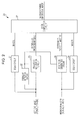
- parallax detection is performed with respect to only either one of the left-eye image L and the right-eye image R and an obtained parallax map is used in both cases generating an externally-provided image LL and generating an externally-provided image RR so as to realize reduction of the circuit scale and reduction of memory capacity.
- Fig. 2 illustrates a configuration example of an image processing circuit 20 realizing reduction of the circuit scale and reduction of memory capacity.
- actually-taken images of two viewpoints which are a left-eye image L actually taken by a left-eye camera and a right-eye image R actually taken by the right-eye camera are inputted.
- the parallax detection circuit 22 When a parallax detection circuit 22 receives the left-eye image L, the parallax detection circuit 22 detects depths, that is, parallax of respective pixels and generates a parallax map for one image frame, for example, so as to output the parallax map to each of a pseudo 3D generation circuit 23 and a pseudo 3D generation circuit 26.
- the pseudo 3D generation circuit 23 When the pseudo 3D generation circuit 23 receives the left-eye image L, the pseudo 3D generation circuit 23 generates an externally-provided image LL which seems to be taken by a pseudo camera externally provided to the left-eye camera L, based on the parallax map generated by the parallax detection circuit 22.
- the delay circuit 21 When a delay circuit 21 receives the left-eye image L, the delay circuit 21 provides outputs the left-eye image L with elapse of delay time during which the pseudo 3D generation circuit 23 generates the externally-provided image LL from the left-eye image L and outputs the image LL.
- the pseudo 3D generation circuit 26 When the other pseudo 3D generation circuit 26 receives the right-eye image R, the pseudo 3D generation circuit 26 generates an externally-provided image RR which seems to be taken by a pseudo camera externally provided to the right-eye camera R, based on the parallax map generated by the parallax detection circuit 22, in a similar manner.
- the delay circuit 24 When a delay circuit 24 receives the right-eye image R, the delay circuit 24 outputs the right-eye image R with elapse of delay time during which the pseudo 3D generation circuit 26 generates the externally-provided image RR from the right-eye image R and outputs the image RR.
- an image composition circuit 27 When an image composition circuit 27 receives the above-described images L, LL, RR, and R on four viewpoints, the image composition circuit 27 discretely arranges respective pixels of the externally-provided images based on a predetermined rule so as to generate and output one composite image.
- the image composition circuit 27 can arbitrarily perform parallax adjustment (same as above).
- the example shown in Fig. 2 employs such configuration that the parallax detection circuit 22 receives the left-eye image L to generate the parallax map and the parallax map is used in both of the pseudo 3D generation circuits 23 and 26 on the left and the right.
- the right-eye image R is inputted and a parallax map which is used in both left and right pseudo 3D generation is generated may be employed.
- each of the number of parallax detection circuits and the number of memories for holding the parallax map can be reduced to one, enabling reduction of the circuit scale.
Applications Claiming Priority (1)
| Application Number | Priority Date | Filing Date | Title |
|---|---|---|---|
| JP2010286716A JP2012134885A (ja) | 2010-12-22 | 2010-12-22 | 画像処理装置及び画像処理方法 |
Publications (2)
| Publication Number | Publication Date |
|---|---|
| EP2469867A2 true EP2469867A2 (de) | 2012-06-27 |
| EP2469867A3 EP2469867A3 (de) | 2013-04-10 |
Family
ID=45421889
Family Applications (1)
| Application Number | Title | Priority Date | Filing Date |
|---|---|---|---|
| EP11192541.8A Withdrawn EP2469867A3 (de) | 2010-12-22 | 2011-12-08 | Bildverarbeitungsvorrichtung und Bildverarbeitungsverfahren |
Country Status (4)
| Country | Link |
|---|---|
| US (1) | US20120163702A1 (de) |
| EP (1) | EP2469867A3 (de) |
| JP (1) | JP2012134885A (de) |
| CN (1) | CN102572493A (de) |
Families Citing this family (3)
| Publication number | Priority date | Publication date | Assignee | Title |
|---|---|---|---|---|
| US9113074B2 (en) * | 2010-12-22 | 2015-08-18 | Olympus Corporation | Imaging apparatus, imaging method, and computer readable storage medium for applying special effects processing to an automatically set region of a stereoscopic image |
| CN103079084B (zh) * | 2013-02-21 | 2015-10-21 | 厦门市羽星智能科技有限责任公司 | 一种有利于实时融合播放的多视点裸眼立体片源存储方式 |
| US10168798B2 (en) * | 2016-09-29 | 2019-01-01 | Tower Spring Global Limited | Head mounted display |
Citations (2)
| Publication number | Priority date | Publication date | Assignee | Title |
|---|---|---|---|---|
| JP2010021731A (ja) | 2008-07-09 | 2010-01-28 | Canon Inc | 画像処理装置、画像処理方法 |
| JP2010226500A (ja) | 2009-03-24 | 2010-10-07 | Toshiba Corp | 立体画像表示装置および立体画像表示方法 |
Family Cites Families (13)
| Publication number | Priority date | Publication date | Assignee | Title |
|---|---|---|---|---|
| US5530774A (en) * | 1994-03-25 | 1996-06-25 | Eastman Kodak Company | Generation of depth image through interpolation and extrapolation of intermediate images derived from stereo image pair using disparity vector fields |
| US6417850B1 (en) * | 1999-01-27 | 2002-07-09 | Compaq Information Technologies Group, L.P. | Depth painting for 3-D rendering applications |
| JP4729812B2 (ja) * | 2001-06-27 | 2011-07-20 | ソニー株式会社 | 画像処理装置および方法、記録媒体、並びにプログラム |
| JP4211292B2 (ja) * | 2002-06-03 | 2009-01-21 | ソニー株式会社 | 画像処理装置および画像処理方法、プログラム並びにプログラム記録媒体 |
| JP4052331B2 (ja) * | 2003-06-20 | 2008-02-27 | 日本電信電話株式会社 | 仮想視点画像生成方法及び3次元画像表示方法並びに装置 |
| US7623676B2 (en) * | 2004-12-21 | 2009-11-24 | Sarnoff Corporation | Method and apparatus for tracking objects over a wide area using a network of stereo sensors |
| WO2007085482A1 (de) * | 2006-01-30 | 2007-08-02 | Newsight Gmbh | Verfahren zur erzeugung und darstellung räumlich wahrnehmbarer bilder |
| ES2727567T3 (es) * | 2007-12-27 | 2019-10-17 | Psholix Ag | Procedimiento y dispositivo para la generación de imágenes multivista en tiempo real |
| WO2010048632A1 (en) * | 2008-10-24 | 2010-04-29 | Real D | Stereoscopic image format with depth information |
| KR101556149B1 (ko) * | 2008-11-27 | 2015-09-30 | 엘지전자 주식회사 | 수신 시스템 및 데이터 처리 방법 |
| WO2011014419A1 (en) * | 2009-07-31 | 2011-02-03 | 3Dmedia Corporation | Methods, systems, and computer-readable storage media for creating three-dimensional (3d) images of a scene |
| KR101729924B1 (ko) * | 2010-08-03 | 2017-04-26 | 삼성전자주식회사 | 영상 크기 조절에 기반한 외삽 뷰 생성 장치 및 방법 |
| KR101666019B1 (ko) * | 2010-08-03 | 2016-10-14 | 삼성전자주식회사 | 외삽 뷰 생성을 위한 장치 및 방법 |
-
2010
- 2010-12-22 JP JP2010286716A patent/JP2012134885A/ja not_active Withdrawn
-
2011
- 2011-12-08 EP EP11192541.8A patent/EP2469867A3/de not_active Withdrawn
- 2011-12-13 US US13/324,042 patent/US20120163702A1/en not_active Abandoned
- 2011-12-15 CN CN201110419822XA patent/CN102572493A/zh active Pending
Patent Citations (2)
| Publication number | Priority date | Publication date | Assignee | Title |
|---|---|---|---|---|
| JP2010021731A (ja) | 2008-07-09 | 2010-01-28 | Canon Inc | 画像処理装置、画像処理方法 |
| JP2010226500A (ja) | 2009-03-24 | 2010-10-07 | Toshiba Corp | 立体画像表示装置および立体画像表示方法 |
Also Published As
| Publication number | Publication date |
|---|---|
| US20120163702A1 (en) | 2012-06-28 |
| EP2469867A3 (de) | 2013-04-10 |
| CN102572493A (zh) | 2012-07-11 |
| JP2012134885A (ja) | 2012-07-12 |
Similar Documents
| Publication | Publication Date | Title |
|---|---|---|
| US8633967B2 (en) | Method and device for the creation of pseudo-holographic images | |
| EP2648414B1 (de) | 3D-Anzeigevorrichtung und Verfahren zur Bildverarbeitung damit | |
| Balram et al. | Light‐field imaging and display systems | |
| US8503764B2 (en) | Method for generating images of multi-views | |
| JP5450330B2 (ja) | 画像処理装置および方法、ならびに立体画像表示装置 | |
| EP2285133A2 (de) | Chip zur erzeugung stereoskopischer bilder für eine mobilvorrichtung und verfahren zur anzeige stereoskopischer bilder damit | |
| CN102474644A (zh) | 立体图像显示系统、视差转换装置、视差转换方法以及程序 | |
| JP2011176800A (ja) | 画像処理装置、立体表示装置及び画像処理方法 | |
| WO2006016315A1 (en) | Detection of view mode | |
| JP2004274642A (ja) | 3次元映像情報の伝送方法 | |
| JP2015534745A (ja) | 立体画像の生成、送信、及び受信方法、及び関連する装置 | |
| EP2469867A2 (de) | Bildverarbeitungsvorrichtung und Bildverarbeitungsverfahren | |
| US20120163700A1 (en) | Image processing device and image processing method | |
| KR20050083352A (ko) | 휴대용 단말장치에서 스테레오 카메라를 이용하여 파노라믹 영상과 3차원 영상을 획득 및 디스플레이를 할 수 있는 장치 및 그 방법. | |
| Lee et al. | Eye tracking based glasses-free 3D display by dynamic light field rendering | |
| US9270980B2 (en) | Autostereoscopic display system and method | |
| JP2011176823A (ja) | 画像処理装置、立体表示装置及び画像処理方法 | |
| KR101093929B1 (ko) | 깊이 지도를 이용하여 3차원 영상을 표시하는 방법 및 시스템 | |
| JP4481275B2 (ja) | 3次元映像情報の伝送方法 | |
| Zinger et al. | iGLANCE project: free-viewpoint 3D video | |
| TWI383660B (zh) | 影像處理方法及影像處理裝置 | |
| KR20150041225A (ko) | 영상 처리 방법 및 장치 | |
| TWI511524B (zh) | 裸眼立體顯示系統及方法 | |
| Swash et al. | Moiré-Free Full Parallax Holoscopic 3D Display based on Cross-Lenticular | |
| CN111935474A (zh) | 一种参展式发光转盘及其图像摄取方法 |
Legal Events
| Date | Code | Title | Description |
|---|---|---|---|
| 17P | Request for examination filed |
Effective date: 20111208 |
|
| AK | Designated contracting states |
Kind code of ref document: A2 Designated state(s): AL AT BE BG CH CY CZ DE DK EE ES FI FR GB GR HR HU IE IS IT LI LT LU LV MC MK MT NL NO PL PT RO RS SE SI SK SM TR |
|
| AX | Request for extension of the european patent |
Extension state: BA ME |
|
| PUAI | Public reference made under article 153(3) epc to a published international application that has entered the european phase |
Free format text: ORIGINAL CODE: 0009012 |
|
| PUAL | Search report despatched |
Free format text: ORIGINAL CODE: 0009013 |
|
| AK | Designated contracting states |
Kind code of ref document: A3 Designated state(s): AL AT BE BG CH CY CZ DE DK EE ES FI FR GB GR HR HU IE IS IT LI LT LU LV MC MK MT NL NO PL PT RO RS SE SI SK SM TR |
|
| AX | Request for extension of the european patent |
Extension state: BA ME |
|
| RIC1 | Information provided on ipc code assigned before grant |
Ipc: H04N 13/00 20060101AFI20130307BHEP |
|
| STAA | Information on the status of an ep patent application or granted ep patent |
Free format text: STATUS: THE APPLICATION HAS BEEN WITHDRAWN |
|
| 18W | Application withdrawn |
Effective date: 20130501 |