EP2469202A2 - Accumulator for refrigeration cycle system - Google Patents
Accumulator for refrigeration cycle system Download PDFInfo
- Publication number
- EP2469202A2 EP2469202A2 EP11194025A EP11194025A EP2469202A2 EP 2469202 A2 EP2469202 A2 EP 2469202A2 EP 11194025 A EP11194025 A EP 11194025A EP 11194025 A EP11194025 A EP 11194025A EP 2469202 A2 EP2469202 A2 EP 2469202A2
- Authority
- EP
- European Patent Office
- Prior art keywords
- refrigerant
- flow
- accumulator
- accumulating chamber
- liquid accumulating
- Prior art date
- Legal status (The legal status is an assumption and is not a legal conclusion. Google has not performed a legal analysis and makes no representation as to the accuracy of the status listed.)
- Withdrawn
Links
Images


Classifications
-
- F—MECHANICAL ENGINEERING; LIGHTING; HEATING; WEAPONS; BLASTING
- F25—REFRIGERATION OR COOLING; COMBINED HEATING AND REFRIGERATION SYSTEMS; HEAT PUMP SYSTEMS; MANUFACTURE OR STORAGE OF ICE; LIQUEFACTION SOLIDIFICATION OF GASES
- F25B—REFRIGERATION MACHINES, PLANTS OR SYSTEMS; COMBINED HEATING AND REFRIGERATION SYSTEMS; HEAT PUMP SYSTEMS
- F25B43/00—Arrangements for separating or purifying gases or liquids; Arrangements for vaporising the residuum of liquid refrigerant, e.g. by heat
- F25B43/006—Accumulators
-
- F—MECHANICAL ENGINEERING; LIGHTING; HEATING; WEAPONS; BLASTING
- F25—REFRIGERATION OR COOLING; COMBINED HEATING AND REFRIGERATION SYSTEMS; HEAT PUMP SYSTEMS; MANUFACTURE OR STORAGE OF ICE; LIQUEFACTION SOLIDIFICATION OF GASES
- F25B—REFRIGERATION MACHINES, PLANTS OR SYSTEMS; COMBINED HEATING AND REFRIGERATION SYSTEMS; HEAT PUMP SYSTEMS
- F25B2400/00—Component parts or details not otherwise provided for in this subclass
- F25B2400/02—Centrifugal separation of gas, liquid or oil
Definitions
- the present invention relates in general to a refrigeration cycle system and more particularly to an accumulator installed in the refrigeration cycle system at a position between an evaporator and a compressor.
- a refrigeration cycle system of vapor-compression type (or heat pump type)
- an accumulator in a refrigerant flow line at a position between an evaporator and a compressor.
- the accumulator has basically two functions, one being to feed the compressor with gaseous refrigerant to prevent the compressor from effecting compression against liquid refrigerant, and the other being to return oil, which circulates in the refrigeration cycle circuit together with the refrigerant, to the compressor.
- the oil is applied to the compressor for lubricating rotating parts of the compressor.
- the oil leaks into the refrigerant.
- accumulator 50 is the known accumulator.
- the known accumulator 50 When in use, the known accumulator 50 is arranged to stand upright as is shown in the drawing.
- the known accumulator 50 comprises a cylindrical case 52 which has a liquid accumulating chamber 51 formed therein, a refrigerant inlet pipe 53 through which refrigerant is led into the liquid accumulating chamber 51, a refrigerant outlet pipe 54 through which the refrigerant is discharged from the liquid accumulating chamber 51 to the outside (viz., to a compressor), stirring vanes 60 which are placed in the liquid accumulating chamber 51 and rotatably disposed around the refrigerant outlet pipe 54, and an electric drive mechanism (not shown) which turns the stirring vanes 60 with electric power.
- the refrigerant inlet pipe 53 has an outlet end 53a that is exposed to an upper part of the liquid accumulating chamber 51, as shown.
- the refrigerant outlet pipe 54 has an inlet end 54a that is exposed to the upper part of the liquid accumulating chamber 51.
- the refrigerant outlet pipe 54 is formed with a plurality of small openings 55 which serve as oil returning openings.
- refrigerant is led into the liquid accumulating chamber 51 from the refrigerant inlet pipe 53 as is indicated by an arrow.
- the refrigerant is then temporarily accumulated in the liquid accumulating chamber 51.
- liquid refrigerant is forced to take a lower position due to its higher specific gravity and gaseous refrigerant is forced to take a higher position due to its lower specific gravity. Since the inlet end 54a of the refrigerant outlet pipe 54 is kept exposed to the upper gaseous part of the liquid accumulating chamber 51, the inlet end 54a sucks only the gaseous refrigerant.
- the gaseous refrigerant thus led into the refrigerant outlet pipe 54 is led to the compressor (not shown).
- liquid refrigerant placed in the lower part (which will be referred to lower liquid part hereinafter) of the liquid accumulating chamber 51 is stirred by the stirring vanes 60.
- oil in the liquid refrigerant is sufficiently mixed with the liquid refrigerant.
- a small amount of oil-mixed liquid refrigerant is led into the refrigerant outlet pipe 54 from the small openings 55 and then led to the compressor.
- an electric drive mechanism is used for driving the stirring vanes 60.
- the known accumulator tends to be complicated in construction and high in cost.
- an object of the present invention is to provide an accumulator for a refrigeration cycle system, which can exhibit its essential function without the aid of electric power.
- Another object of the present invention is to provide an accumulator for a refrigeration cycle system, which can exhibit its essential function without inducting complicated and high cost construction.
- a still another object of the present invention is to provide an accumulator for a refrigeration cycle system, which can exhibit a sufficient oil circulation rate (OCR) even in a low temperature condition of an associated refrigeration cycle system.
- OCR oil circulation rate
- an accumulator (1A, 1B) for use in a refrigeration cycle system which comprises a liquid accumulating chamber (2) in which refrigerant is accumulated; a refrigerant inlet port (4a) through which the refrigerant is led into the liquid accumulating chamber (2); a refrigerant outlet pipe (5) that has an upstream open end (5a) exposed to an upper part of the liquid accumulating chamber (2) to discharge the refrigerant from the liquid accumulating chamber (2) to the outside of the chamber (2); an oil return opening (6) provided in a given part of the refrigerant outlet pipe (5) to return oil, which is contained in the refrigerant in the lower part of the liquid accumulating chamber (2), to a compressor of the refrigeration cycle system; a refrigerant flow generating structure (10, 30a, 30b) that provides the refrigerant from the refrigerant inlet port (4a) with a given flow, the given flow being produced by a drive force possessed by the refrigerant
- FIG. 1A there is shown an accumulator 1A of a first embodiment of the present invention for a refrigeration cycle system.
- the accumulator 1A of the first embodiment is arranged to stand upright when in use.
- the accumulator 1A comprises a cylindrical case 3 that has a cylindrical liquid accumulating chamber 2 formed therein, a refrigerant inlet pipe 4 through which refrigerant is led into the liquid accumulating chamber 2 from an evaporator (not shown), a refrigerant outlet pipe 5 through which the refrigerant is discharged from the liquid accumulating chamber 2 to the outside (viz., compressor), a flow guide device 10 which provides the refrigerant from the refrigerant inlet pipe 4 with a whirling movement and an interference ridge portion 21 which provides the whirled flow of refrigerant from the flow guide device 10 with up-and-down movement (or stirs the whirled flow of refrigerant in up-and-down direction).
- the refrigerant outlet pipe 5 is a straight pipe, as shown.
- the cylindrical case 3 has an upper end closed by a circular head wall (no numeral) and a cylindrical inner surface 2a that constitutes an inner side wall of the liquid accumulating chamber 2.
- the refrigerant inlet pipe 4 is integral with the upper head wall of the cylindrical case 3 and has an outlet end 4a exposed to an upper part of the liquid accumulating chamber 2.
- the outlet end 4a of the refrigerant inlet pipe 4 is positioned at a center of the upper head wall of the cylindrical case 3.
- the refrigerant inlet pipe 4 is connected to a refrigerant outlet port of the evaporator (not shown).
- the straight refrigerant outlet pipe 5 is arranged to pass through a center of the liquid accumulating chamber 2 and through a center of a circular bottom member 20 that is press-fitted into the lower open end of the cylindrical case 3 and fitted to the case 3 by a known connector (not shown).
- the above-mentioned interference ridge portion 21 is integrally formed on the circular bottom member 20.
- the refrigerant outlet pipe 5 has an inlet end 5a that is exposed to the upper part of the liquid accumulating chamber 2.
- the inlet end 5a of the refrigerant outlet pipe 5 is directed to the outlet end 4a of the refrigerant inlet pipe 4 keeping a given clearance therebetween.
- the refrigerant outlet pipe 5 is formed at a portion near the interference ridge portion 21 with a small opening 6 which serves as an oil returning opening.
- the refrigerant outlet pipe 5 is connected to a refrigerant inlet port of the compressor (not shown).
- the flow guide device 10 is a cylindrical member with an engraved upper head. As shown, the cylindrical flow guide device 10 is concentrically disposed in the upper part of the liquid accumulating chamber 2 and fixed to the circular head of the cylindrical case 3 through three screws (no numerals). Upon tight installation of the flow guide device 10, there is defined an annular clearance "d" between the cylindrical flow guide device 10 and the cylindrical inner surface 2a of the case 3, as shown.
- the flow guide device 10 comprises a cylindrical side wall 12 and a circular upper head 11.
- the circular upper head 11 is formed at its upper surface with a recessed flow guide portion which comprises a circular center recess 11a that faces the outlet end 4a of the refrigerant inlet pipe 4 and three equally spaced curved grooves 11b that extend radially outward from the circular center recess 11a to the annular clearance "d".
- the interference ridge portion 21 extends diametrically on the circular bottom member 20.
- the ridge portion 21 has at a middle position thereof an enlarged circular part 21c through which a lower part of the refrigerant outlet pipe 5 passes.
- the interference ridge portion 21 has a trapezoidal cross section and comprises a top wall 21d and first and second inclined side walls 21a and 21b which extend obliquely downward from the top wall 21d, as shown.
- Each of the first and second inclined side walls 21a and 21b defines an obtuse angle to a base surface defined by an upper flat surface of the circular bottom member 20.
- refrigerant from the evaporator (not shown) is led into the liquid accumulating chamber 2 of the accumulator 1A through the refrigerant inlet pipe 4.
- the refrigerant is at first led or dropped into the circular center recess 11a of the flow guide device 10 and then forced to flow in the three curved grooves 11b by the force of its kinetic energy and its own weight.
- the refrigerant flowing in each curved groove 11b is then dropped into the liquid accumulating chamber 2 through the annular clearance "d".
- the refrigerant having just passed through the grooves 11b shows a whirling movement along the cylindrical inner surface 2a of the case 3 and thus, in the lower part of the case 3, the refrigerant is whirled, as is shown in Fig. 1 .
- the whirled flow of refrigerant is forced to move upward and downward thereby moving the whirled flow of refrigerant in up-and-down direction. More specifically, due to provision of the first inclined side wall 21a, the whirled flow of refrigerant is moved upward and then due to provision of the second inclined side wall 21b, the flow is moved downward. With such upward and downward movement of the whirled flow, the refrigerant in the lower part of the liquid accumulating chamber 2 is enforcedly mixed or stirred.
- the oil-mixed liquid refrigerant in the lower part of the accumulator 1A is effectively stirred or mixed without the aid of electric power. That is, the accumulator 1A can be produced without inducing complicated and high cost construction, and can exhibit a sufficient oil circulation rate (OCR) even in a low temperature condition of the refrigeration cycle system.
- OCR oil circulation rate
- the flow guide device 10 provides the refrigerant led into the accumulator 1A with a whirling movement by practically using the force of kinetic energy and the own weight of the refrigerant. That is, in the first embodiment, such whirling flow of refrigerant is produced by a simple construction.
- the small opening 6 is provided near the interference ridge portion 21. This is because mixing of refrigerant is most effectively carried out near the interference ridge portion 21. Thus, the oil-mixed liquid refrigerant can be assuredly led to the compressor together with a certain amount of oil.
- a modified interference ridge portion 21A there is shown a modified interference ridge portion 21A.
- the second inclined side wall 21b' has a vertical surface, as shown.
- Substantially same function as the above-mentioned interference ridge portion 21 is expected.
- FIG. 5 to 7 there is shown an accumulator 1B of a second embodiment of the present invention for a refrigeration cycle system.
- the accumulator 1B of the second embodiment is arranged to stand upright when in use, like in such a posture as shown in Figs. 6 and 7 .
- the accumulator 1B comprises a rectangular case 3 that has a rectangular liquid accumulating chamber 2 formed therein, first and second partition walls 30a and 30b that are alternately arranged in the chamber 2 to define therein first, second and third flow passages 2a, 2b and 2c that are connected in series in zigzag manner, a refrigerant inlet pipe 4 through which refrigerant is led into an upstream part of the first flow passage 2a, a refrigerant outlet pipe 5 through which the refrigerant is discharged from a downstream part of the third flow passage 2c to the outside, and a plurality of flow guide members 31 and 32 that are arranged in the third flow passage 2c.
- the refrigerant inlet pipe 4 is connected to an upper position of one side wall of the case 3 so that the refrigerant from an outlet end 4a of the inlet pipe 4 is fed to the first flow passage 2a from an upper position.
- the refrigerant inlet pipe 4 is connected to an outlet port of an evaporator.
- the refrigerant outlet pipe 5 is connected to a lower position of the other side wall of the case 3.
- the pipe 5 has an upright portion 5b placed in the downstream part of the third flow passage 2c.
- An inlet end 5a of the upright portion 5b is exposed to an upper part of the downstream part of the third flow passage 2c, as shown.
- the refrigerant outlet pipe 5 is formed at a position near a base part of the upright portion 5b with a small opening 6 which serves as an oil returning opening.
- the refrigerant outlet pipe 5 is connected to a refrigerant inlet port of a compressor (not shown).
- the first partition wall 30a is connected at its left end to the left side wall of the case 3 leaving the right end thereof from the right side wall of the case 3, and the second partition wall 30b is connected at its right end to the right side wall of the case 3 leaving the left end thereof from the left side wall of the case 3.
- a sufficiently long zigzag flow passage including the first, second and third flow passages 2a, 2b and 2c is provided.
- the flow guide members 31 and 32 are arranged in the third flow passage 2c.
- the flow guide members 31 are secured to a larger wall of the case 3 and the other flow guide members 32 are secured to the second partition wall 30b.
- each flow guide member 31 or 32 is inclined in such a manner that a height of the member 31 or 32 relative to a bottom wall of the case 3 increases as a distance to the refrigerant outlet pipe 5 reduces, as shown.
- the flow guide members 31 and 32 are alternately arranged with respect a direction in which the refrigerant flows.
- refrigerant is led to the first flow passage 2a from the refrigerant inlet pipe 4 and then guided to flow in the second and third flow passages 2b and 2c in zigzag manner. That is, due to provision of the first and second partition walls 30a and 30b, the refrigerant led into the liquid accumulating chamber 2 is forced to have a zigzag flow as is seen from the arrows shown in the drawing.
- the refrigerant led to the third flow passage 2c is forced to move upward and downward due to provision of the flow guide members 31 and 32. With such upward and downward movement, the refrigerant in the third flow passage 2c is enforcedly mixed or stirred.
- the oil-mixed liquid refrigerant in the accumulator 1B is effectively stirred or mixed without the aid of electric power.
- the zigzag flow of the refrigerant is easily produced by the two partition walls 30a and 30b. That is, in the second embodiment, such zigzag flow of refrigerant is produced by a simple construction.
- the accumulator 1B of the second embodiment can be produced without inducing complicated and high cost construction and can exhibit a sufficient oil circulation rate (OCR) even in a low temperature condition of the refrigeration cycle system.
- OCR oil circulation rate
- the flow guide device 10 and the two partition walls 30a and 30b are used for providing the flow of refrigerant with a whirling movement and zigzag movement respectively.
- such movement may be produced by other devices.
- the interference ridge portion 21 and the flow guide members 31 and 32 are used to move the flow of refrigerant upward and downward for effectively mixing the refrigerant in the liquid accumulating chamber 2.
- such upward and downward movement may be produced by other devices.
Landscapes
- Engineering & Computer Science (AREA)
- Thermal Sciences (AREA)
- Analytical Chemistry (AREA)
- Power Engineering (AREA)
- Physics & Mathematics (AREA)
- Mechanical Engineering (AREA)
- Chemical & Material Sciences (AREA)
- General Engineering & Computer Science (AREA)
- Applications Or Details Of Rotary Compressors (AREA)
- Air-Conditioning For Vehicles (AREA)
- Compressor (AREA)
- Other Air-Conditioning Systems (AREA)
- Devices That Are Associated With Refrigeration Equipment (AREA)
Abstract
Description
- The present invention relates in general to a refrigeration cycle system and more particularly to an accumulator installed in the refrigeration cycle system at a position between an evaporator and a compressor.
- In a refrigeration cycle system of vapor-compression type (or heat pump type), there is arranged an accumulator in a refrigerant flow line at a position between an evaporator and a compressor. The accumulator has basically two functions, one being to feed the compressor with gaseous refrigerant to prevent the compressor from effecting compression against liquid refrigerant, and the other being to return oil, which circulates in the refrigeration cycle circuit together with the refrigerant, to the compressor. Actually, the oil is applied to the compressor for lubricating rotating parts of the compressor. However, under operation of the refrigeration cycle system, the oil leaks into the refrigerant.
- One of the accumulators having such two functions is shown in Japanese Laid-open Patent Application (Tokkai)
2004-324899 - In order to clarify the feature of the present invention, the accumulator of this Japanese Laid-open Patent Application will be briefly described with the aid of
Fig. 8 that shows schematically the known accumulator. - In
Fig. 8 , denoted bynumeral 50 is the known accumulator. When in use, theknown accumulator 50 is arranged to stand upright as is shown in the drawing. - The known
accumulator 50 comprises acylindrical case 52 which has a liquid accumulatingchamber 51 formed therein, arefrigerant inlet pipe 53 through which refrigerant is led into the liquid accumulatingchamber 51, arefrigerant outlet pipe 54 through which the refrigerant is discharged from theliquid accumulating chamber 51 to the outside (viz., to a compressor), stirringvanes 60 which are placed in the liquid accumulatingchamber 51 and rotatably disposed around therefrigerant outlet pipe 54, and an electric drive mechanism (not shown) which turns the stirringvanes 60 with electric power. Therefrigerant inlet pipe 53 has anoutlet end 53a that is exposed to an upper part of theliquid accumulating chamber 51, as shown. Therefrigerant outlet pipe 54 has aninlet end 54a that is exposed to the upper part of theliquid accumulating chamber 51. Therefrigerant outlet pipe 54 is formed with a plurality ofsmall openings 55 which serve as oil returning openings. - In operation of an associated refrigeration cycle system, refrigerant is led into the liquid accumulating
chamber 51 from therefrigerant inlet pipe 53 as is indicated by an arrow. The refrigerant is then temporarily accumulated in theliquid accumulating chamber 51. During the temporal accumulation, liquid refrigerant is forced to take a lower position due to its higher specific gravity and gaseous refrigerant is forced to take a higher position due to its lower specific gravity. Since theinlet end 54a of therefrigerant outlet pipe 54 is kept exposed to the upper gaseous part of theliquid accumulating chamber 51, theinlet end 54a sucks only the gaseous refrigerant. The gaseous refrigerant thus led into therefrigerant outlet pipe 54 is led to the compressor (not shown). During this, the liquid refrigerant placed in the lower part (which will be referred to lower liquid part hereinafter) of theliquid accumulating chamber 51 is stirred by the stirringvanes 60. Thus, oil in the liquid refrigerant is sufficiently mixed with the liquid refrigerant. Then, a small amount of oil-mixed liquid refrigerant is led into therefrigerant outlet pipe 54 from thesmall openings 55 and then led to the compressor. - Usually, when it is very cold, for example, when the outside air temperature is lower than -25°C, it tends to occur that oil is separated from the oil-mixed liquid refrigerant due to difference in specific gravity and viscosity. In the known accumulator, such undesired separation is suppressed by the stirring work of the stirring
vanes 60. Thus, in the known accumulator, a sufficient oil circulation rate (OCR) can be obtained in the refrigeration cycle system. - However, in the above-mentioned known accumulator, an electric drive mechanism is used for driving the stirring
vanes 60. This means that it is necessary to provide an electric power source (or motor), a link mechanism extending between the power source and each stirringvane 60 and an electrically insulated construction for electric power transmission. Thus, the known accumulator tends to be complicated in construction and high in cost. - Accordingly, it is an object of the present invention to provide an accumulator for a refrigeration cycle system, which is free of the above-mentioned drawbacks.
- That is, an object of the present invention is to provide an accumulator for a refrigeration cycle system, which can exhibit its essential function without the aid of electric power.
- Another object of the present invention is to provide an accumulator for a refrigeration cycle system, which can exhibit its essential function without inducting complicated and high cost construction.
- A still another object of the present invention is to provide an accumulator for a refrigeration cycle system, which can exhibit a sufficient oil circulation rate (OCR) even in a low temperature condition of an associated refrigeration cycle system.
- In accordance with the present invention, there is provided an accumulator (1A, 1B) for use in a refrigeration cycle system, which comprises a liquid accumulating chamber (2) in which refrigerant is accumulated; a refrigerant inlet port (4a) through which the refrigerant is led into the liquid accumulating chamber (2); a refrigerant outlet pipe (5) that has an upstream open end (5a) exposed to an upper part of the liquid accumulating chamber (2) to discharge the refrigerant from the liquid accumulating chamber (2) to the outside of the chamber (2); an oil return opening (6) provided in a given part of the refrigerant outlet pipe (5) to return oil, which is contained in the refrigerant in the lower part of the liquid accumulating chamber (2), to a compressor of the refrigeration cycle system; a refrigerant flow generating structure (10, 30a, 30b) that provides the refrigerant from the refrigerant inlet port (4a) with a given flow, the given flow being produced by a drive force possessed by the refrigerant; and a refrigerant flow mixing structure (21, 31, 32) that provides the given flow of refrigerant from the refrigerant flow generating structure (10, 30a, 30b) with an upward-and-downward movement thereby to mix the refrigerant.
- Other objects and advantages of the present invention will become apparent from the following description when taken in conjunction with the accompanying drawings, in which:
-
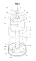
Fig. 1 is a perspective view of an accumulator of a first embodiment of the present invention; -
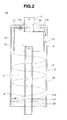
Fig. 2 is a sectional view of the accumulator of the first embodiment of the present invention; -
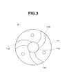
Fig. 3 is a plan view of a flow guide device employed in the accumulator of the first embodiment; -
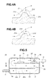
Fig. 4A is an enlarged sectional view of an interference ridge portion employed in the accumulator of the first embodiment; -
Fig. 4B is a view similar toFig. 4A , but showing a modified interference ridge portion; -
Fig. 5 is a horizontally sectional view of an accumulator of a second embodiment of the present invention; -
Fig. 6 is a vertically sectional view taken along the line VI-VI ofFig. 5 ; -
Fig. 7 is a perspective view of a part of the accumulator of the second embodiment showing an arrangement of flow guide members; and -
Fig. 8 is a vertically sectional view of a known accumulator. - In the following, the present invention will be described in detail with reference to the accompanying drawings.
- For ease of understanding, in the following description, various directional terms, such as, upper, lower, right, left, upward and the like, are used. However, such terms are to be understood with respect to only a drawing or drawings on which corresponding portion or part is shown.
- Referring to
Figs. 1 to 4 , there is shown anaccumulator 1A of a first embodiment of the present invention for a refrigeration cycle system. - Like the above-mentioned
known accumulator 50 ofFig. 8 , theaccumulator 1A of the first embodiment is arranged to stand upright when in use. - As is well shown in
Figs. 1 and2 , theaccumulator 1A comprises acylindrical case 3 that has a cylindricalliquid accumulating chamber 2 formed therein, arefrigerant inlet pipe 4 through which refrigerant is led into theliquid accumulating chamber 2 from an evaporator (not shown), arefrigerant outlet pipe 5 through which the refrigerant is discharged from the liquid accumulatingchamber 2 to the outside (viz., compressor), aflow guide device 10 which provides the refrigerant from therefrigerant inlet pipe 4 with a whirling movement and aninterference ridge portion 21 which provides the whirled flow of refrigerant from theflow guide device 10 with up-and-down movement (or stirs the whirled flow of refrigerant in up-and-down direction). Therefrigerant outlet pipe 5 is a straight pipe, as shown. - As is seen from
Figs. 1 and2 , thecylindrical case 3 has an upper end closed by a circular head wall (no numeral) and a cylindricalinner surface 2a that constitutes an inner side wall of theliquid accumulating chamber 2. - As is seen from
Fig. 2 , therefrigerant inlet pipe 4 is integral with the upper head wall of thecylindrical case 3 and has anoutlet end 4a exposed to an upper part of theliquid accumulating chamber 2. - As is seen from
Figs. 1 and2 , theoutlet end 4a of therefrigerant inlet pipe 4 is positioned at a center of the upper head wall of thecylindrical case 3. Therefrigerant inlet pipe 4 is connected to a refrigerant outlet port of the evaporator (not shown). - As is seen from
Figs. 1 and2 , the straightrefrigerant outlet pipe 5 is arranged to pass through a center of theliquid accumulating chamber 2 and through a center of acircular bottom member 20 that is press-fitted into the lower open end of thecylindrical case 3 and fitted to thecase 3 by a known connector (not shown). - As is seen from
Fig. 1 , the above-mentionedinterference ridge portion 21 is integrally formed on thecircular bottom member 20. Therefrigerant outlet pipe 5 has aninlet end 5a that is exposed to the upper part of theliquid accumulating chamber 2. - As shown, the
inlet end 5a of therefrigerant outlet pipe 5 is directed to theoutlet end 4a of therefrigerant inlet pipe 4 keeping a given clearance therebetween. - The
refrigerant outlet pipe 5 is formed at a portion near theinterference ridge portion 21 with asmall opening 6 which serves as an oil returning opening. Therefrigerant outlet pipe 5 is connected to a refrigerant inlet port of the compressor (not shown). - As is seen from
Figs. 1 ,2 and3 , theflow guide device 10 is a cylindrical member with an engraved upper head. As shown, the cylindricalflow guide device 10 is concentrically disposed in the upper part of theliquid accumulating chamber 2 and fixed to the circular head of thecylindrical case 3 through three screws (no numerals). Upon tight installation of theflow guide device 10, there is defined an annular clearance "d" between the cylindricalflow guide device 10 and the cylindricalinner surface 2a of thecase 3, as shown. - More specifically, the
flow guide device 10 comprises acylindrical side wall 12 and a circularupper head 11. - As is seen from
Figs. 1 to 3 , the circularupper head 11 is formed at its upper surface with a recessed flow guide portion which comprises acircular center recess 11a that faces theoutlet end 4a of therefrigerant inlet pipe 4 and three equally spacedcurved grooves 11b that extend radially outward from thecircular center recess 11a to the annular clearance "d". - As will be seen from
Fig. 2 , in operation of the associated refrigeration cycle system, refrigerant is led to thecircular center recess 11a from therefrigerant inlet pipe 4 and then guided to flow radially outward by the threecurved grooves 11b. The refrigerant then falls into the annular clearance "d" and then into the lower part of theliquid accumulating chamber 2. - As is seen from
Fig. 1 , theinterference ridge portion 21 extends diametrically on thecircular bottom member 20. Theridge portion 21 has at a middle position thereof an enlargedcircular part 21c through which a lower part of therefrigerant outlet pipe 5 passes. - As is seen from
Fig. 4A , theinterference ridge portion 21 has a trapezoidal cross section and comprises atop wall 21d and first and secondinclined side walls top wall 21d, as shown. Each of the first and secondinclined side walls circular bottom member 20. - In the following, operation will be described with the aid of
Figs. 1 ,2 and4A . - Under operation of the associated refrigeration cycle system, refrigerant from the evaporator (not shown) is led into the
liquid accumulating chamber 2 of theaccumulator 1A through therefrigerant inlet pipe 4. As will be easily understood fromFigs. 1 and2 , during this flow, the refrigerant is at first led or dropped into thecircular center recess 11a of theflow guide device 10 and then forced to flow in the threecurved grooves 11b by the force of its kinetic energy and its own weight. The refrigerant flowing in eachcurved groove 11b is then dropped into theliquid accumulating chamber 2 through the annular clearance "d". - Because of the curved shape of the
grooves 11b, the refrigerant having just passed through thegrooves 11b shows a whirling movement along the cylindricalinner surface 2a of thecase 3 and thus, in the lower part of thecase 3, the refrigerant is whirled, as is shown inFig. 1 . - As will be understood from
Fig. 4A , due to provision of theinterference ridge portion 21, the whirled flow of refrigerant is forced to move upward and downward thereby moving the whirled flow of refrigerant in up-and-down direction. More specifically, due to provision of the firstinclined side wall 21a, the whirled flow of refrigerant is moved upward and then due to provision of the secondinclined side wall 21b, the flow is moved downward. With such upward and downward movement of the whirled flow, the refrigerant in the lower part of theliquid accumulating chamber 2 is enforcedly mixed or stirred. - Even when the outside air temperature is very low (for example, lower than -25°C) which would induce a possibility of separation of oil from the oil-mixed liquid refrigerant in the
liquid accumulating chamber 2, such undesired oil separation is suppressed due to the enforced mixing of the oil-mixed liquid refrigerant. - As is seen from
Fig. 2 , under such very cold condition, a small amount of the oil-mixed liquid refrigerant placed in the lower part of theliquid accumulating chamber 2 is permitted to flow into therefrigerant outlet pipe 5 from thesmall opening 6 and then led or returned to the compressor (not shown), and the gaseous refrigerant placed at the upper part of theliquid accumulating chamber 2 is led into therefrigerant outlet pipe 5 from theinlet end 5a and led to the refrigerant inlet port of the compressor. - As will be understood from the above, in the first embodiment of the present invention, the oil-mixed liquid refrigerant in the lower part of the
accumulator 1A is effectively stirred or mixed without the aid of electric power. That is, theaccumulator 1A can be produced without inducing complicated and high cost construction, and can exhibit a sufficient oil circulation rate (OCR) even in a low temperature condition of the refrigeration cycle system. - In the first embodiment, the
flow guide device 10 provides the refrigerant led into theaccumulator 1A with a whirling movement by practically using the force of kinetic energy and the own weight of the refrigerant. That is, in the first embodiment, such whirling flow of refrigerant is produced by a simple construction. - Because of the cylindrical
inner surface 2a of thecase 3, the whirling flow of refrigerant produced by theflow guide device 10 is smoothly promoted. - Due to provision of
interference ridge portion 21, the whirling flow of refrigerant is forced to move upward and downward and thus, the refrigerant in theliquid accumulating chamber 2 is effectively stirred and mixed. - It is to be noted that the
small opening 6 is provided near theinterference ridge portion 21. This is because mixing of refrigerant is most effectively carried out near theinterference ridge portion 21. Thus, the oil-mixed liquid refrigerant can be assuredly led to the compressor together with a certain amount of oil. - Referring to
Fig. 4B , there is shown a modifiedinterference ridge portion 21A. In this modification, the secondinclined side wall 21b' has a vertical surface, as shown. Substantially same function as the above-mentionedinterference ridge portion 21 is expected. - Referring to
Figs. 5 to 7 , there is shown anaccumulator 1B of a second embodiment of the present invention for a refrigeration cycle system. - The
accumulator 1B of the second embodiment is arranged to stand upright when in use, like in such a posture as shown inFigs. 6 and 7 . - As will be understood from
Fig. 5 which is a horizontally sectrional view of theaccumulator 1B, theaccumulator 1B comprises arectangular case 3 that has a rectangularliquid accumulating chamber 2 formed therein, first andsecond partition walls chamber 2 to define therein first, second andthird flow passages refrigerant inlet pipe 4 through which refrigerant is led into an upstream part of thefirst flow passage 2a, arefrigerant outlet pipe 5 through which the refrigerant is discharged from a downstream part of thethird flow passage 2c to the outside, and a plurality offlow guide members third flow passage 2c. - As will be seen from
Fig. 6 , therefrigerant inlet pipe 4 is connected to an upper position of one side wall of thecase 3 so that the refrigerant from anoutlet end 4a of theinlet pipe 4 is fed to thefirst flow passage 2a from an upper position. Although not shown in the drawing, therefrigerant inlet pipe 4 is connected to an outlet port of an evaporator. - As is best shown in
Fig. 7 , therefrigerant outlet pipe 5 is connected to a lower position of the other side wall of thecase 3. Thepipe 5 has anupright portion 5b placed in the downstream part of thethird flow passage 2c. Aninlet end 5a of theupright portion 5b is exposed to an upper part of the downstream part of thethird flow passage 2c, as shown. - As is seen from
Figs. 6 and 7 , therefrigerant outlet pipe 5 is formed at a position near a base part of theupright portion 5b with asmall opening 6 which serves as an oil returning opening. Therefrigerant outlet pipe 5 is connected to a refrigerant inlet port of a compressor (not shown). - As is seen from
Fig. 5 , thefirst partition wall 30a is connected at its left end to the left side wall of thecase 3 leaving the right end thereof from the right side wall of thecase 3, and thesecond partition wall 30b is connected at its right end to the right side wall of thecase 3 leaving the left end thereof from the left side wall of thecase 3. With this, a sufficiently long zigzag flow passage including the first, second andthird flow passages - As is understood from
Figs. 5 to 7 , theflow guide members third flow passage 2c. Theflow guide members 31 are secured to a larger wall of thecase 3 and the otherflow guide members 32 are secured to thesecond partition wall 30b. - As is well shown in
Fig. 7 , eachflow guide member member case 3 increases as a distance to therefrigerant outlet pipe 5 reduces, as shown. As is seen from the drawings, theflow guide members - As will be seen from
Fig. 5 , in operation of the associated refrigeration cycle system, refrigerant is led to thefirst flow passage 2a from therefrigerant inlet pipe 4 and then guided to flow in the second andthird flow passages second partition walls liquid accumulating chamber 2 is forced to have a zigzag flow as is seen from the arrows shown in the drawing. - As will be seen from
Figs. 6 and 7 , the refrigerant led to thethird flow passage 2c is forced to move upward and downward due to provision of theflow guide members third flow passage 2c is enforcedly mixed or stirred. - Even when the outside air temperature is very low (for example, lower than -25°C) which would induce a possibility of separation of oil from the oil-mixed liquid refrigerant in the
liquid accumulating chamber 2, such undesired oil separation is suppressed due to the enforced mixing of the oil-mixed liquid refrigerant. - As is seen from
Fig. 7 , under such very cold condition, a small amount of the oil-mixed liquid refrigerant placed in the lower part of thethird flow passage 2c is permitted to flow into therefrigerant outlet pipe 5 from thesmall opening 6 and then led or returned to the compressor (not shown), and the gaseous refrigerant placed at the upper part of thethird flow passage 2c is led into therefrigerant outlet pipe 5 from theinlet end 5a and led to the refrigerant inlet port of the compressor. - As will be understood from the above, also in the second embodiment of the present invention, the oil-mixed liquid refrigerant in the
accumulator 1B is effectively stirred or mixed without the aid of electric power. - In the second embodiment, the zigzag flow of the refrigerant is easily produced by the two
partition walls - Due to provision of the
flow guide members third flow passage 2c is forced to move upward and downward and thus, the refrigerant in theliquid accumulating chamber 2 is effectively stirred and mixed. - That is, the
accumulator 1B of the second embodiment can be produced without inducing complicated and high cost construction and can exhibit a sufficient oil circulation rate (OCR) even in a low temperature condition of the refrigeration cycle system. - In the above-mentioned first and
second embodiments flow guide device 10 and the twopartition walls - In the above-mentioned first and
second embodiments interference ridge portion 21 and theflow guide members liquid accumulating chamber 2. However, if desired, such upward and downward movement may be produced by other devices. - Although the invention has been described above with reference to the embodiments of the invention, the invention is not limited to such embodiments as described above. Various modifications and variations of such embodiments may be carried out by those skilled in the art, in light of the above description.
Claims (12)
- An accumulator (1A, 1B) for use in a refrigeration cycle system, comprising:a case (3) having a liquid accumulating chamber (2) defined therein, the liquid accumulating chamber (2) forming a gaseous part in an upper portion thereof and a liquid part in a lower portion thereof when the refrigeration cycle system is in operation;a refrigerant inlet pipe (4) through which refrigerant is led into the liquid accumulating chamber (2);a refrigerant outlet pipe (5) having an upstream open end (5a) exposed to the gaseous part of the liquid accumulating chamber (2), a middle part placed in the liquid part of the liquid accumulating chamber (2) and a downstream open end exposed to the outside of the case (3);a first flow guide device (10, 30a, 30b) installed in the liquid accumulating chamber (2) at a position near the refrigerant inlet pipe (4) to provide the refrigerant from the refrigerant inlet pipe (4) with a predetermined flow, the predetermined flow being produced by a kinetic energy possessed by the refrigerant;a second flow guide device (21, 31, 32) installed in the liquid accumulating chamber (2) at a position remote from the refrigerant inlet pipe (4) to provide the flow of refrigerant from the first flow guide device (10, 301, 30b) with an upward and downward movement; andan opening (6) formed in the middle part of the refrigerant outlet pipe (5) at a position near the second flow guide device (21, 31, 32) to discharge a certain small amount of refrigerant in the liquid part to the outside through the refrigerant outlet pipe (5).
- An accumulator (1A) as claimed in Claim 1, in which the first flow guide device (10) is constructed and arranged to provide the refrigerant from the refrigerant inlet pipe (4) with a whirling flow.
- An accumulator (1A) as claimed in Claim 1 or 2, in which the liquid accumulating chamber (2) is defined by a cylindrical inner surface (2a) of the case (3), and in which the first flow guide device (10) is cylindrical and concentrically disposed in the gaseous part of the liquid accumulating chamber (2).
- An accumulator (1A) as claimed in Claim 1, 2 or 3, in which the refrigerant outlet pipe (5) is a straight pipe which extends coaxially in the cylindrical liquid accumulating chamber (2) with its inlet end (5a) connected to an outlet end (4a) of the refrigerant inlet pipe (4) and its outlet end exposed to the outside of the case (3).
- An accumulator (1A) as claimed in Claim 1, 2, 3 or 4, in which the first flow guide device (10) comprises:a cylindrical side wall (12) concentrically disposed in the gaseous part of the cylindrical liquid accumulating chamber (2) leaving an annular clearance "d" between the cylindrical side wall (12) and the cylindrical inner wall (2a) of the case (3), the annular clearance "d" being connected to the liquid part of the liquid accumulating chamber (2); anda circular upper head (11) connected to an upper portion of the case (3) and formed with a recessed flow guide portion by which the whirling flow of refrigerant is produced.
- An accumulator (1A) as claimed in Claim 5, in which the recessed flow guide portion of the circular upper head (11) comprises:a circular center recess (11a) that faces the outlet end (4a) of the refrigerant inlet pipe (4); anda plurality of mutually spaced curved grooves (11b) that extends radially outward from the circular center recess (11a) to the annular clearance (d).
- An accumulator (1A) as claimed in Claim 6, in which the mutually spaced curved grooves (11b) are equally spaced three curved grooves (11b).
- An accumulator (1A) as claimed in Claim 2, in which the second flow guide device (21) comprises an interference ridge portion integrally formed on a bottom member (20) of the case (3) at a position near the opening (6) of the middle part of the refrigerant outlet pipe (5).
- An accumulator (1A) as claimed in Claim 8, in which the interference ridge portion has a generally trapezoidal cross section.
- An accumulator (1B) as claimed in Claim 1, 2, 3, 4, 5, 6, 7, 8 or 9, in which the first guide device (30a, 30b) are constructed to provide the refrigerant from the refrigerant inlet pipe (4) with a zigzag flow.
- An accumulator (1B) as claimed in Claim 1, 2, 3, 4, 5, 6, 7, 8, 9 or 10, in which the liquid accumulating chamber (2) is rectangular in shape, and in which the first flow guide device (30a, 30b) comprises first and second partition walls (30a, 30b) that are alternately arranged in the chamber (2) to define therein first, second and third flow passages (2a, 2b,2c) which are connected in series, the refrigerant inlet pipe (4) being connected to an upstream part of the first flow passage (2a), and the refrigerant outlet pipe (5) being connected to a downstream part of the third flow passage (2c).
- An accumulator (1B) as claimed in Claim 1, 2, 3, 4, 5, 6, 7, 8, 9, 10 or 11, in which the second flow guide device (31, 32) comprises:first flow guide members (31) that are secured to one side wall of the third flow passage; andsecond flow guide members (32) that are secured to the other side wall of the third flow passage,wherein the first and second guide members (31, 32) are alternately arranged with respect to a direction in which the refrigerant flows, andwherein each of the first and second guide members (31, 32) is inclined in such a manner that a height of the member (31, 32) relative to a bottom wall of the case increases as a distance to the refrigerant outlet pipe (5) reduces.
Applications Claiming Priority (1)
| Application Number | Priority Date | Filing Date | Title |
|---|---|---|---|
| JP2010284282A JP5644469B2 (en) | 2010-12-21 | 2010-12-21 | accumulator |
Publications (2)
| Publication Number | Publication Date |
|---|---|
| EP2469202A2 true EP2469202A2 (en) | 2012-06-27 |
| EP2469202A3 EP2469202A3 (en) | 2013-05-29 |
Family
ID=45349408
Family Applications (1)
| Application Number | Title | Priority Date | Filing Date |
|---|---|---|---|
| EP11194025.0A Withdrawn EP2469202A3 (en) | 2010-12-21 | 2011-12-16 | Accumulator for refrigeration cycle system |
Country Status (4)
| Country | Link |
|---|---|
| US (1) | US20120151957A1 (en) |
| EP (1) | EP2469202A3 (en) |
| JP (1) | JP5644469B2 (en) |
| CN (1) | CN102538320B (en) |
Cited By (2)
| Publication number | Priority date | Publication date | Assignee | Title |
|---|---|---|---|---|
| EP3118545A1 (en) * | 2015-07-14 | 2017-01-18 | Fujikoki Corporation | Accumulator |
| WO2020040476A1 (en) | 2018-08-22 | 2020-02-27 | Hanon Systems | Accumulator, optionally in combination with an internal heat exchanger in a shared housing |
Families Citing this family (12)
| Publication number | Priority date | Publication date | Assignee | Title |
|---|---|---|---|---|
| CN104061725B (en) * | 2014-05-29 | 2016-06-08 | 佛山晓世科技服务有限公司 | A kind of air condition compressor reservoir of improvement |
| JP6661345B2 (en) * | 2015-07-14 | 2020-03-11 | 株式会社不二工機 | accumulator |
| CN105588381B (en) * | 2015-08-27 | 2018-11-30 | 青岛海信日立空调系统有限公司 | A kind of gas and oil separating plant |
| US10539350B2 (en) * | 2016-02-26 | 2020-01-21 | Daikin Applied Americas Inc. | Economizer used in chiller system |
| KR101817227B1 (en) * | 2016-07-01 | 2018-01-10 | 이근식 | Stabilization device for refrigerant gas |
| CN106091496B (en) * | 2016-07-29 | 2022-07-05 | 青岛开拓隆海制冷配件有限公司 | Liquid storage device for carbon dioxide refrigerant |
| CZ308314B6 (en) * | 2017-08-31 | 2020-05-06 | Hanon Systems | A cyclone for separating a gas-liquid mixture, a refrigerant accumulator containing the cyclone |
| KR101906116B1 (en) * | 2018-04-30 | 2018-10-08 | 주식회사 우성초음파 | Agitation apparatus for refrigerant having mesh assembly |
| KR101903937B1 (en) * | 2018-04-30 | 2018-10-02 | 주식회사 우성초음파 | Agitation apparatus for refrigerant having impeller |
| KR102142022B1 (en) * | 2018-07-26 | 2020-08-06 | 주식회사 스마트링크 | Refrigerant gas stabilization system and That control method |
| DE102021125240A1 (en) | 2020-11-20 | 2022-05-25 | Hanon Systems | Device for separating a gaseous and a liquid phase of a working substance and for storing the liquid phase |
| US12699427B2 (en) * | 2023-09-28 | 2026-08-04 | Amd Design, Llc | Fluid cleaning apparatus for a computing system |
Citations (1)
| Publication number | Priority date | Publication date | Assignee | Title |
|---|---|---|---|---|
| JP2004324899A (en) | 2003-04-21 | 2004-11-18 | Matsushita Electric Ind Co Ltd | Gas-liquid separator |
Family Cites Families (26)
| Publication number | Priority date | Publication date | Assignee | Title |
|---|---|---|---|---|
| US1737702A (en) * | 1928-03-05 | 1929-12-03 | Joseph E Bond | Agitator |
| US3271304A (en) * | 1964-06-26 | 1966-09-06 | Pacific Flush Tank Co | Venturi aerator and aerating process for waste treatment |
| JPS517765U (en) * | 1974-07-03 | 1976-01-20 | ||
| JPS5733768A (en) * | 1980-08-06 | 1982-02-23 | Matsushita Electric Industrial Co Ltd | Accumulator |
| JPS6028370U (en) * | 1983-07-29 | 1985-02-26 | ダイキン工業株式会社 | Accumulator |
| JPS6113271U (en) * | 1984-06-27 | 1986-01-25 | 株式会社東芝 | compressor suction cup |
| JPS62141167U (en) * | 1986-02-28 | 1987-09-05 | ||
| US4651540A (en) * | 1986-03-21 | 1987-03-24 | Tecumseh Products Company | Suction accumulator including an entrance baffle |
| JPH07289407A (en) * | 1994-04-25 | 1995-11-07 | Nario Ariki | Eating device |
| US5507159A (en) * | 1994-04-25 | 1996-04-16 | Tecumseh Products Company | Suction accumulator vibration damper |
| US6109778A (en) * | 1997-09-22 | 2000-08-29 | United States Filter Corporation | Apparatus for homogeneous mixing of a solution with tangential jet outlets |
| US6196019B1 (en) * | 1997-12-16 | 2001-03-06 | Showa Aluminum Corporation | Accumulator |
| US6062039A (en) * | 1998-01-07 | 2000-05-16 | Parker-Hannifin Corporation | Universal accumulator for automobile air conditioning systems |
| JP3352968B2 (en) * | 1999-02-01 | 2002-12-03 | 株式会社日本レオナード商会 | Steam supply device |
| US6202437B1 (en) * | 1999-05-19 | 2001-03-20 | Carrier Corporation | Suction accumulator pre-charged with oil |
| US6167720B1 (en) * | 1999-10-19 | 2001-01-02 | Automotive Fluid Systems, Inc. | Accumulator baffle molded from desiccant |
| US6311514B1 (en) * | 2000-04-07 | 2001-11-06 | Automotive Fluid Systems, Inc. | Refrigeration accumulator having a matrix wall structure |
| JP2001330343A (en) * | 2000-05-19 | 2001-11-30 | Fujitsu General Ltd | Accumulator for compressor |
| US6430958B1 (en) * | 2001-01-22 | 2002-08-13 | Halla Climate Control Canada, Inc. | Suction accumulator for air conditioning systems |
| JP2002307054A (en) * | 2001-04-12 | 2002-10-22 | Daikin Ind Ltd | Gas-liquid separator of ozone water generator and ozone water generator |
| US6880360B2 (en) * | 2002-10-03 | 2005-04-19 | York International Corporation | Compressor systems for use with smokeless lubricant |
| US7267477B1 (en) * | 2004-10-07 | 2007-09-11 | Broad Reach Companies, Llc | Fluid blending utilizing either or both passive and active mixing |
| KR100784611B1 (en) * | 2006-08-18 | 2007-12-11 | 주식회사 두원공조 | Gas-liquid separator with internal heat exchanger of cooling system |
| FI120893B (en) * | 2006-10-16 | 2010-04-15 | Vahterus Oy | Arrangement and method for separating droplets from evaporated refrigerant |
| DE102008028852A1 (en) * | 2008-06-19 | 2009-12-24 | Behr Gmbh & Co. Kg | Refrigerant collector with liquid separator |
| US8967852B2 (en) * | 2010-09-17 | 2015-03-03 | Delavan Inc | Mixers for immiscible fluids |
-
2010
- 2010-12-21 JP JP2010284282A patent/JP5644469B2/en not_active Expired - Fee Related
-
2011
- 2011-09-05 CN CN201110264385.9A patent/CN102538320B/en not_active Expired - Fee Related
- 2011-10-27 US US13/283,019 patent/US20120151957A1/en not_active Abandoned
- 2011-12-16 EP EP11194025.0A patent/EP2469202A3/en not_active Withdrawn
Patent Citations (1)
| Publication number | Priority date | Publication date | Assignee | Title |
|---|---|---|---|---|
| JP2004324899A (en) | 2003-04-21 | 2004-11-18 | Matsushita Electric Ind Co Ltd | Gas-liquid separator |
Cited By (5)
| Publication number | Priority date | Publication date | Assignee | Title |
|---|---|---|---|---|
| EP3118545A1 (en) * | 2015-07-14 | 2017-01-18 | Fujikoki Corporation | Accumulator |
| US10190809B2 (en) | 2015-07-14 | 2019-01-29 | Fujikoki Corporation | Accumulator |
| WO2020040476A1 (en) | 2018-08-22 | 2020-02-27 | Hanon Systems | Accumulator, optionally in combination with an internal heat exchanger in a shared housing |
| EP3841336A4 (en) * | 2018-08-22 | 2022-05-25 | Hanon Systems | ACCUMULATOR, OPTIONALLY IN COMBINATION WITH AN INTERNAL HEAT EXCHANGER IN A COMMON HOUSING |
| US11865895B2 (en) | 2018-08-22 | 2024-01-09 | Hanon Systems | Accumulator, optionally in combination with an internal heat exchanger in a shared housing |
Also Published As
| Publication number | Publication date |
|---|---|
| CN102538320A (en) | 2012-07-04 |
| US20120151957A1 (en) | 2012-06-21 |
| JP5644469B2 (en) | 2014-12-24 |
| JP2012132608A (en) | 2012-07-12 |
| EP2469202A3 (en) | 2013-05-29 |
| CN102538320B (en) | 2014-10-29 |
Similar Documents
| Publication | Publication Date | Title |
|---|---|---|
| US20120151957A1 (en) | Accumulator for refrigeration cycle system | |
| EP2674699B1 (en) | Gas liquid separator and refrigeration cycle device | |
| EP1568955B1 (en) | Oil separator and cooling-cycle apparatus using the same | |
| CN104903594B (en) | Ejector | |
| EP2778569B1 (en) | Air conditioner | |
| CN107726676B (en) | Heat exchanger shell and tube, heat exchanger and air conditioner | |
| JP2008202894A (en) | Oil separator | |
| CN113167266A (en) | Compressor and air conditioner | |
| US20150290603A1 (en) | Stirrer having recesses formed inside container | |
| CN104879288B (en) | Air suction silencer and there is its compressor | |
| JP5757415B2 (en) | Refrigeration equipment such as air conditioners | |
| JP5712775B2 (en) | accumulator | |
| JP6854973B2 (en) | Compressor | |
| CN211449025U (en) | Fluid compressor | |
| CN110312871B (en) | Compressor and refrigeration cycle device | |
| US9664190B2 (en) | Compressor | |
| CN115750356B (en) | Compressor and refrigeration equipment | |
| JP4899641B2 (en) | Mixed fluid separator | |
| CN204984776U (en) | Suction silencer and compressor provided with same | |
| CN115507033B (en) | Compressor convenient to oil-gas separation | |
| EP3517859A1 (en) | Refrigeration cycle apparatus | |
| CN105221469A (en) | Oil-gas separation device and compressor having same | |
| CN206468533U (en) | Horizontal compressor | |
| JP5067298B2 (en) | Hermetic compressor | |
| CN223909798U (en) | Gas-liquid separator, heat pump air conditioning system and vehicle |
Legal Events
| Date | Code | Title | Description |
|---|---|---|---|
| 17P | Request for examination filed |
Effective date: 20111216 |
|
| AK | Designated contracting states |
Kind code of ref document: A2 Designated state(s): AL AT BE BG CH CY CZ DE DK EE ES FI FR GB GR HR HU IE IS IT LI LT LU LV MC MK MT NL NO PL PT RO RS SE SI SK SM TR |
|
| AX | Request for extension of the european patent |
Extension state: BA ME |
|
| PUAI | Public reference made under article 153(3) epc to a published international application that has entered the european phase |
Free format text: ORIGINAL CODE: 0009012 |
|
| PUAL | Search report despatched |
Free format text: ORIGINAL CODE: 0009013 |
|
| AK | Designated contracting states |
Kind code of ref document: A3 Designated state(s): AL AT BE BG CH CY CZ DE DK EE ES FI FR GB GR HR HU IE IS IT LI LT LU LV MC MK MT NL NO PL PT RO RS SE SI SK SM TR |
|
| AX | Request for extension of the european patent |
Extension state: BA ME |
|
| RIC1 | Information provided on ipc code assigned before grant |
Ipc: F25B 43/00 20060101AFI20130419BHEP |
|
| STAA | Information on the status of an ep patent application or granted ep patent |
Free format text: STATUS: THE APPLICATION IS DEEMED TO BE WITHDRAWN |
|
| 18D | Application deemed to be withdrawn |
Effective date: 20160701 |